WO2017188021A1 - Électrode d'élément électrochimique et batterie secondaire au lithium-ion - Google Patents
Électrode d'élément électrochimique et batterie secondaire au lithium-ion Download PDFInfo
- Publication number
- WO2017188021A1 WO2017188021A1 PCT/JP2017/015233 JP2017015233W WO2017188021A1 WO 2017188021 A1 WO2017188021 A1 WO 2017188021A1 JP 2017015233 W JP2017015233 W JP 2017015233W WO 2017188021 A1 WO2017188021 A1 WO 2017188021A1
- Authority
- WO
- WIPO (PCT)
- Prior art keywords
- electrode
- current collector
- negative electrode
- positive electrode
- lithium ion
- Prior art date
- Legal status (The legal status is an assumption and is not a legal conclusion. Google has not performed a legal analysis and makes no representation as to the accuracy of the status listed.)
- Ceased
Links
Images


Classifications
-
- H—ELECTRICITY
- H01—ELECTRIC ELEMENTS
- H01G—CAPACITORS; CAPACITORS, RECTIFIERS, DETECTORS, SWITCHING DEVICES, LIGHT-SENSITIVE OR TEMPERATURE-SENSITIVE DEVICES OF THE ELECTROLYTIC TYPE
- H01G11/00—Hybrid capacitors, i.e. capacitors having different positive and negative electrodes; Electric double-layer [EDL] capacitors; Processes for the manufacture thereof or of parts thereof
- H01G11/66—Current collectors
- H01G11/70—Current collectors characterised by their structure
-
- H—ELECTRICITY
- H01—ELECTRIC ELEMENTS
- H01M—PROCESSES OR MEANS, e.g. BATTERIES, FOR THE DIRECT CONVERSION OF CHEMICAL ENERGY INTO ELECTRICAL ENERGY
- H01M10/00—Secondary cells; Manufacture thereof
- H01M10/05—Accumulators with non-aqueous electrolyte
- H01M10/052—Li-accumulators
-
- H—ELECTRICITY
- H01—ELECTRIC ELEMENTS
- H01M—PROCESSES OR MEANS, e.g. BATTERIES, FOR THE DIRECT CONVERSION OF CHEMICAL ENERGY INTO ELECTRICAL ENERGY
- H01M10/00—Secondary cells; Manufacture thereof
- H01M10/05—Accumulators with non-aqueous electrolyte
- H01M10/058—Construction or manufacture
- H01M10/0587—Construction or manufacture of accumulators having only wound construction elements, i.e. wound positive electrodes, wound negative electrodes and wound separators
-
- H—ELECTRICITY
- H01—ELECTRIC ELEMENTS
- H01M—PROCESSES OR MEANS, e.g. BATTERIES, FOR THE DIRECT CONVERSION OF CHEMICAL ENERGY INTO ELECTRICAL ENERGY
- H01M4/00—Electrodes
- H01M4/02—Electrodes composed of, or comprising, active material
- H01M4/13—Electrodes for accumulators with non-aqueous electrolyte, e.g. for lithium-accumulators; Processes of manufacture thereof
-
- H—ELECTRICITY
- H01—ELECTRIC ELEMENTS
- H01M—PROCESSES OR MEANS, e.g. BATTERIES, FOR THE DIRECT CONVERSION OF CHEMICAL ENERGY INTO ELECTRICAL ENERGY
- H01M4/00—Electrodes
- H01M4/02—Electrodes composed of, or comprising, active material
- H01M4/36—Selection of substances as active materials, active masses, active liquids
- H01M4/48—Selection of substances as active materials, active masses, active liquids of inorganic oxides or hydroxides
-
- H—ELECTRICITY
- H01—ELECTRIC ELEMENTS
- H01M—PROCESSES OR MEANS, e.g. BATTERIES, FOR THE DIRECT CONVERSION OF CHEMICAL ENERGY INTO ELECTRICAL ENERGY
- H01M4/00—Electrodes
- H01M4/02—Electrodes composed of, or comprising, active material
- H01M4/64—Carriers or collectors
- H01M4/70—Carriers or collectors characterised by shape or form
- H01M4/72—Grids
- H01M4/74—Meshes or woven material; Expanded metal
-
- H—ELECTRICITY
- H01—ELECTRIC ELEMENTS
- H01M—PROCESSES OR MEANS, e.g. BATTERIES, FOR THE DIRECT CONVERSION OF CHEMICAL ENERGY INTO ELECTRICAL ENERGY
- H01M6/00—Primary cells; Manufacture thereof
- H01M6/02—Details
-
- Y—GENERAL TAGGING OF NEW TECHNOLOGICAL DEVELOPMENTS; GENERAL TAGGING OF CROSS-SECTIONAL TECHNOLOGIES SPANNING OVER SEVERAL SECTIONS OF THE IPC; TECHNICAL SUBJECTS COVERED BY FORMER USPC CROSS-REFERENCE ART COLLECTIONS [XRACs] AND DIGESTS
- Y02—TECHNOLOGIES OR APPLICATIONS FOR MITIGATION OR ADAPTATION AGAINST CLIMATE CHANGE
- Y02E—REDUCTION OF GREENHOUSE GAS [GHG] EMISSIONS, RELATED TO ENERGY GENERATION, TRANSMISSION OR DISTRIBUTION
- Y02E60/00—Enabling technologies; Technologies with a potential or indirect contribution to GHG emissions mitigation
- Y02E60/10—Energy storage using batteries
-
- Y—GENERAL TAGGING OF NEW TECHNOLOGICAL DEVELOPMENTS; GENERAL TAGGING OF CROSS-SECTIONAL TECHNOLOGIES SPANNING OVER SEVERAL SECTIONS OF THE IPC; TECHNICAL SUBJECTS COVERED BY FORMER USPC CROSS-REFERENCE ART COLLECTIONS [XRACs] AND DIGESTS
- Y02—TECHNOLOGIES OR APPLICATIONS FOR MITIGATION OR ADAPTATION AGAINST CLIMATE CHANGE
- Y02P—CLIMATE CHANGE MITIGATION TECHNOLOGIES IN THE PRODUCTION OR PROCESSING OF GOODS
- Y02P70/00—Climate change mitigation technologies in the production process for final industrial or consumer products
- Y02P70/50—Manufacturing or production processes characterised by the final manufactured product
Definitions
- the present invention relates to an electrode for an electrochemical element excellent in reliability and a lithium ion secondary battery having the electrode.
- lithium ion secondary batteries have high voltage and high capacity, there are great expectations for their development.
- such a high capacity negative electrode material has a large irreversible capacity, and a relatively large amount of Li released from the positive electrode by the initial charge of the battery and occluded in the high capacity negative electrode material is negative during the next discharge.
- the battery capacity could not be sufficiently increased due to the use of a high capacity negative electrode material.
- the positive electrode current collector and the negative electrode current collector having through-holes are used for various purposes other than the pre-doping as described above, for example, for the purpose of maintaining good properties of the electrode mixture layer. (Patent Document 2, etc.).
- an electrode mixture layer (a positive electrode mixture layer containing a positive electrode active material or a negative electrode mixture layer containing a negative electrode active material such as a high-capacity negative electrode material) is obtained using a current collector having a plurality of through holes.
- an electrode in the form of a tab is formed by a portion of the current collector that is exposed without being formed, or when a lithium ion secondary battery is formed using such an electrode, the current is collected at a specific portion of the electrode. It has been clarified by the present inventors that defects such as body breakage tend to occur.
- the present invention has been made in view of the above circumstances, and an object thereof is to provide an electrode for an electrochemical element excellent in reliability and a lithium ion secondary battery having the electrode.
- the electrode for an electrochemical element of the present invention that can achieve the above object is used for the positive electrode or the negative electrode of an electrochemical element having a wound electrode body in which a positive electrode and a negative electrode are wound through a separator.
- the main body is a rectangle having a pair of short sides and a pair of long sides in a plan view, and the current collector has a plurality of through holes penetrating from one side to the other side.
- the plurality of through holes are regularly arranged, and a straight line connecting one through hole and the other through hole closest to the one through hole is parallel to the short side of the main body portion. It is characterized by not existing within the range of 0 ° ⁇ 20 ° from any direction.
- the lithium ion secondary battery of the present invention has a wound electrode body in which a positive electrode and a negative electrode are wound via a separator, and a non-aqueous electrolyte, and at least the positive electrode is the present invention.
- This is an electrode for an electrochemical element.
- an electrochemical element electrode having excellent reliability and a lithium ion secondary battery having the electrode.
- Electrode for electrochemical device of the present invention is used as a positive electrode or a negative electrode of an electrochemical element such as a lithium ion secondary battery, a lithium primary battery, or a capacitor.
- the electrode of the present invention includes a main body (electrode) having an electrode mixture layer (positive electrode mixture layer or negative electrode mixture layer) containing an electrode active material (positive electrode active material or negative electrode active material) on one side or both sides of a current collector. It has a mixture layer forming part) and is exposed to form a part of the current collector without forming an electrode mixture layer, and is used to electrically connect the part to other members of the electrochemical element. And a tab portion adapted to do so.
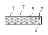
- FIG. 1 is a plan view schematically showing an example of the electrode (positive electrode) of the present invention.
- An electrode (positive electrode) 10 shown in FIG. 1 has an electrode mixture layer (positive electrode mixture layer) 11 on the surface of a current collector 12.
- a portion having the electrode mixture layer 11 is a main body portion (electrode mixture layer forming portion).
- the electrode 10 is provided with a tab portion 13 composed of an exposed portion where the electrode mixture layer is not formed on both surfaces of the current collector 12.
- the tab portion 13 is provided with a positive electrode tab 14.
- the main body of the electrode shown in FIG. 1 is rectangular in plan view (the shape of the main body described below means the shape in plan view unless otherwise specified).
- the electrode (positive electrode) of the present invention comprises a main body portion (electrode mixture layer forming portion) having an electrode mixture layer (positive electrode mixture layer) on the surface of a current collector, and a tab portion.
- the tab portion 13 is provided at the right end of the electrode (positive electrode) 10, but may be provided near the center of the electrode (positive electrode) 10.
- the main body portion of the electrode (positive electrode) may be divided into a plurality of locations (usually two locations) (the same applies when the electrode of the present invention is a negative electrode).
- the current collector according to the electrode of the present invention has a plurality of through holes penetrating from one side to the other side.
- These through holes of the current collector have, for example, an effect of increasing the adhesion between the electrode mixture layer and the current collector, and also serve as a passage for the non-aqueous electrolyte solution of the electrochemical element. Since the non-aqueous electrolyte can penetrate more uniformly throughout the mixture layer, it contributes to improving the characteristics of the electrochemical device.
- the through hole of the current collector according to the electrode of the present invention has Since the Li ion released from the Li supply source (non-aqueous electrolyte containing the released Li ion) becomes a path, it becomes possible to advance pre-doping more efficiently.
- FIG. 1 in order to avoid that drawing becomes complicated, the through-hole is not shown in the exposed part of the electrical power collector 12 which comprises the tab part 13.
- FIG. 1 in order to avoid that drawing becomes complicated, the through-hole is not shown in the exposed part of the electrical power collector 12 which comprises the tab part 13.
- the negative electrode expands greatly due to charging.
- the stress caused by the expansion of the negative electrode is applied to the negative electrode or the stress (pushing pressure) due to the expansion of the negative electrode. Pressure) is applied to the positive electrode.
- the present inventors have an influence on the arrangement of a plurality of through holes provided in the current collector. I found out. That is, in a current collector having a plurality of through holes, anisotropy occurs in the ease of tearing depending on the arrangement of these through holes, and the direction in which tearing is easier is parallel to the short side direction of the rectangular main body. When facing a direction that is close to parallel (that is, a direction that is parallel or close to parallel to the short-side direction of the rectangular current collector), cracks and breaks in the tab portion and the main body portion are likely to occur. . The reason is as follows.
- an electrode wound as in the present invention is conveyed while applying a tension in a long side direction in a manufacturing process, and a tab is installed and wound.
- the direction in which the current collector is easily torn is parallel or nearly parallel to the short side direction of the main body (parallel to the short side direction of the current collector). If it is oriented in a direction close to parallel), cracks are likely to occur in that direction of the electrode.
- the current collector does not tear during the manufacturing process, cracks may occur due to the residual strain of the current collector due to the expansion and contraction of the electrode during charge and discharge after the electrode is made an electrochemical element. There is.
- the part where the tab is welded to the current collector is susceptible to mechanical damage.
- a current collector having a plurality of through holes has a lower strength than that of a normal current collector having no through holes, and is more significantly damaged.
- the tab is welded and fixed to the exterior body. Therefore, if the electrode expands or contracts during charge and discharge and deforms, the tab and the current collector cannot follow the deformation. Cracks and breaks are likely to occur at the welded part. In particular, cracks and breaks tend to occur in a direction parallel to the short side direction of the rectangular main body (a direction parallel to the short side direction of the rectangular current collector).
- the arrangement of the plurality of through holes in the current collector used for the electrode is adjusted, and the direction in which the current collector is more easily torn is parallel and nearly parallel to the short side direction of the rectangular main body ( By preventing the rectangular current collector from facing the short side of the rectangular current collector), it is possible to prevent the occurrence of cracks and breaks in the tab part and body part as described above, and to improve reliability. It is possible to provide excellent electrodes.
- a plurality of through holes are regularly arranged, and a straight line connecting one through hole and another through hole closest to the through hole. Is not in the range of 0 ° ⁇ 20 ° from the direction parallel to the short side direction of the rectangular main body (the direction parallel to the short side direction of the rectangular current collector).
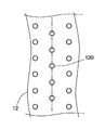
- FIG. 2 is a plan view schematically showing an example of the arrangement of the through holes in the current collector used for the electrode of the present invention.
- the current collector 12 shown in FIG. 2 has a plurality of through holes (indicated by circles in the figure) that penetrate from one side to the other side.
- each through hole is arranged in a specific pattern, specifically, in a staggered arrangement, and includes one through hole 120 and six surrounding holes. The distances from the through holes are all equal, and these six through holes correspond to the through hole closest to one through hole 120.
- straight lines connecting the through holes 120 and the six through holes closest to the through holes 120 are indicated by alternate long and short dash lines, but the current collector 12 is easily split along the direction indicated by the alternate long and short dashed lines. . Therefore, in the electrode of the present invention, when a current collector in which a plurality of through holes are arranged in the pattern shown in FIG. 2 is used, the direction indicated by the alternate long and short dash line in the figure is the short of the rectangular main body. The direction of the current collector is adjusted so that it does not exist within the range of 0 ° ⁇ 20 ° from the direction parallel to the side (the direction parallel to the short side of the rectangular current collector 12).
- the electrode when the electrode is manufactured, the electrochemical element is manufactured, and further, when the lithium ion secondary battery is used, the direction in which the tab portion and the main body portion of the electrode are likely to be cracked or broken easily breaks the current collector. Since the direction does not match, the reliability of the electrode can be improved.
- FIG. 3 and 4 are plan views schematically showing another example of the arrangement of the through holes in the current collector used for the electrode of the present invention.
- the current collector 12 shown in FIG. 3 is an example in which the through holes (indicated by circles in the figure) are arranged in a staggered arrangement. Since the interval between the upper and lower rows is narrower, a straight line (one-dot chain line in the figure) connecting one through hole 120 and the other through hole closest to the through hole 120 exists only in the vertical direction in the figure.
- the downward direction in the figure is a direction parallel to the short side of the rectangular main body (rectangular current collector). The direction of the current collector is adjusted so that it does not exist within the range of 0 ° ⁇ 20 ° from the direction parallel to the short side of the electric body 12.
- each through hole (indicated by a circle in the figure) is arranged linearly in the vertical direction and the horizontal direction in the figure, that is, arranged in a parallel arrangement (series arrangement).
- the interval between the upper and lower columns and the interval between the left and right columns in the drawing of the through hole are the same. Therefore, in the current collector shown in FIG. 4, straight lines (one-dot chain lines in the figure) connecting one through hole 120 and the other through hole closest to the through hole 120 exist in the vertical direction and the horizontal direction in the figure. is doing.
- the vertical direction and the horizontal direction in the figure are directions parallel to the short side of the rectangular main body ( The direction of the current collector is adjusted so that it does not exist within the range of 0 ° ⁇ 20 ° from the direction parallel to the short side of the rectangular current collector 12.
- the arrangement of the plurality of through holes in the current collector according to the electrode of the present invention is not limited to that shown in FIGS. 2 to 4, but is regularly arranged, more specifically, a specific pattern is repeated. As long as they are arranged.
- One type of repeated pattern may be used, or two or more types may be used.
- the average diameter of the through-holes in the current collector is such that when the through-holes are used as Li ions (non-aqueous electrolyte containing the same), the current distribution and the electrodes are improved by the through-holes. From the standpoint of ensuring better the effect of improving the adhesion with the mixture layer, it is preferably 1 ⁇ m or more, and more preferably 50 ⁇ m or more. In addition, since the strength of the current collector may decrease if the size of the through hole is too large, the average diameter of the through holes in the current collector is preferably 400 ⁇ m or less, and more preferably 350 ⁇ m or less. preferable.
- the average diameter of the through-holes in the current collector referred to in this specification is determined by observing the current collector with a scanning electron microscope (SEM) and measuring the rectangular shape of the electrode body portion of at least 20 through-holes in the field of view. This is a value obtained by measuring the diameter in a direction parallel to the short side of the main body and a direction perpendicular to the short side using a scale and calculating the average of these as the average diameter.
- SEM scanning electron microscope
- the porosity of the current collector having a plurality of through-holes can be determined from the viewpoint of improving the flow when the through-hole is a passage for Li ions (non-aqueous electrolyte containing the same), Is preferably 3% or more, and more preferably 8% or more from the viewpoint of better ensuring the effect of enhancing the adhesion between the current collector and the electrode mixture layer.
- the porosity of the current collector having a plurality of through holes is preferably 50% or less. More preferably, it is 45% or less.
- the distance between one through hole in the current collector having a plurality of through holes and the other through hole closest to the through hole is 30 to It is preferable that it is 1000 micrometers.
- the distance between the two through holes in this specification is calculated by observing the current collector with an SEM, measuring the distance between at least 40 sets of through holes in the field of view using a scale, and averaging these. It is the value.
- an electrode for a lithium ion secondary battery (a positive electrode for a lithium ion secondary battery or a negative electrode for a lithium ion secondary battery) which is a main embodiment of the electrode of the present invention.
- the electrode mixture layer will be described later in the section of a lithium ion secondary battery).
- the current collector is a punching metal made of aluminum or aluminum alloy, or an aluminum foil or aluminum alloy foil with through holes formed by etching. Can be used.
- the thickness of the current collector is preferably 6 to 30 ⁇ m.
- the current collector used is a punching metal made of copper or copper alloy, or a copper foil or copper alloy foil with through holes formed by etching. can do.
- the thickness of the current collector is preferably 6 to 30 ⁇ m.
- the lithium ion secondary battery of the present invention includes an electrode body (winding electrode body) in which a positive electrode and a negative electrode are wound via a separator, a non-aqueous electrolyte, And at least the positive electrode of the positive electrode and the negative electrode is the electrode of the present invention.
- the negative electrode is also preferably the electrode of the present invention, although depending on the aspect of the Li supply source other than the positive electrode.
- the electrode of the present invention can be used for the negative electrode as necessary.
- the negative electrode has the same configuration as that of the electrode of the present invention except that the current collector has a through-hole, and the current collector is regular.
- a straight line connecting a through hole and another through hole closest to the through hole is zero from a direction parallel to the short side direction of the rectangular main body.
- a negative electrode having the same configuration as that of the electrode of the present invention can be used except that it is within the range of ⁇ 20 °.
- the positive electrode mixture layer (the electrode mixture layer when the electrode of the present invention is used as a positive electrode) according to the positive electrode of the battery of the present invention contains a positive electrode active material (electrode active material).
- a positive electrode active material electrode active material
- a conductive additive and a binder are included.
- a metal oxide composed of a metal M (Co, Mn, Ni, Ti, Fe, etc.) other than Li and Li can be used. More specifically, lithium cobalt oxide such as LiCoO 2 ; lithium manganese oxide such as LiMnO 2 and Li 2 MnO 3 ; lithium nickel oxide such as LiNiO 2 ; lithium having a layered structure such as LiCo 1-x NiO 2 Containing complex oxide; lithium-containing complex oxide having a spinel structure such as LiMn 2 O 4 , Li 4/3 Ti 5/3 O 4 ; lithium-containing complex oxide having an olivine structure such as LiFePO 4 ; Examples include lithium-containing composite oxides such as oxides substituted with various elements as compositions.
- lithium cobalt oxide such as LiCoO 2 ; lithium manganese oxide such as LiMnO 2 and Li 2 MnO 3 ; lithium nickel oxide such as LiNiO 2 ; lithium having a layered structure such as LiCo 1-x NiO 2 Containing complex oxide; lithium-containing complex oxide
- the positive electrode mixture layer usually contains a conductive additive and a binder.
- a conductive additive such as carbon blacks such as graphite, acetylene black, ketjen black, channel black, furnace black, lamp black and thermal black; carbon fiber; Conductive fibers such as fibers; carbon fluoride; metal powders such as aluminum; zinc oxide; conductive whiskers such as potassium titanate; conductive metal oxides such as titanium oxide; organic conductive materials such as polyphenylene derivatives ; Can also be used.
- PVDF polyvinylidene fluoride
- PTFE polytetrafluoroethylene
- SBR styrene butadiene rubber
- the thickness of the positive electrode mixture layer is preferably, for example, 10 to 100 ⁇ m per one side of the current collector.
- the amount of the positive electrode active material is preferably 65 to 98% by mass
- the amount of the binder is preferably 0.5 to 15% by mass
- the conductive auxiliary agent Is preferably 0.5 to 20% by mass.
- the positive electrode mixture layer is, for example, a paste-like or slurry-like positive electrode mixture in which a positive electrode active material, a binder, and a conductive auxiliary agent are dispersed in an organic solvent such as N-methyl-2-pyrrolidone (NMP) or a solvent such as water.
- NMP N-methyl-2-pyrrolidone
- Prepare an agent-containing composition (however, the binder may be dissolved in a solvent), apply it to one or both sides of the current collector, dry it, and then apply a press treatment such as calendering if necessary. It can form through the process to give.
- the negative electrode mixture layer (the electrode mixture layer when the electrode of the present invention is used as a negative electrode) according to the negative electrode of the battery of the present invention contains a negative electrode active material (electrode active material).
- a binder is included.
- Examples of the negative electrode active material include graphite [natural graphite such as scale-like graphite; artificial graphite obtained by graphitizing easily graphitized carbon such as pyrolytic carbons, mesophase carbon microbeads (MCMB) and carbon fibers at 2800 ° C. or more; ], Pyrolytic carbons, cokes, glassy carbons, fired organic polymer compounds, MCMB, carbon fibers, activated carbon and other carbon materials; metals that can be alloyed with lithium (Si, Sn, etc.), and these These materials include metals (alloys, oxides, etc.), and one or more of these can be used.
- negative electrode active materials materials containing Si and O as constituent elements (provided that the atomic ratio x of O to Si is 0.5 ⁇ x ⁇ 1.5. x ”)) is preferred. Since SiO x is a so-called high capacity negative electrode material, the capacity of the electrode (negative electrode) can be increased by using this as a negative electrode active material.
- a negative electrode using a high-capacity negative electrode material such as SiO x greatly expands when the battery is charged, as described above, in a lithium ion secondary battery using such a negative electrode, a positive electrode or a negative electrode current collector is used.
- the current collector is easily broken as described above.
- the negative electrode contains a high-capacity negative electrode material such as SiO x as the negative electrode active material
- the positive electrode current collector is broken because the electrode of the present invention is used for the positive electrode.
- breakage of the negative electrode current collector can be suppressed well.
- the SiO x may contain Si microcrystal or amorphous phase.
- the atomic ratio of Si and O is a ratio including Si microcrystal or amorphous phase Si. That is, SiO x includes a structure in which Si (for example, microcrystalline Si) is dispersed in an amorphous SiO 2 matrix, and this amorphous SiO 2 is dispersed in the SiO 2 matrix. It is sufficient that the atomic ratio x satisfies 0.5 ⁇ x ⁇ 1.5 in combination with Si.
- x 1, so that the structural formula is represented by SiO.
- a material having such a structure for example, in X-ray diffraction analysis, a peak due to the presence of Si (microcrystalline Si) may not be observed, but when observed with a transmission electron microscope, the presence of fine Si Can be confirmed.
- SiO x is compounded with a carbon material.
- the surface of SiO x is preferably covered with a carbon material. Since SiO x has poor conductivity, when it is used as a negative electrode active material, from the viewpoint of securing good battery characteristics, a conductive material (conductive aid) is used, and SiO x and conductive material in the negative electrode are used. Therefore, it is necessary to form a good conductive network by mixing and dispersing with each other. If complexes complexed with carbon material SiO x, for example, simply than with a material obtained by mixing a conductive material such as SiO x and the carbon material, good conductive network in the negative electrode Formed.
- the composite in which the surface of SiO x is coated with a carbon material is further combined with a conductive material (carbon material or the like), a better conductive network can be formed in the negative electrode.
- a battery with higher capacity and more excellent battery characteristics (for example, charge / discharge cycle characteristics).
- the complex of the SiO x and the carbon material coated with a carbon material for example, like granules the mixture was further granulated with SiO x and the carbon material coated with a carbon material.
- SiO x whose surface is coated with a carbon material
- the surface of a composite (for example, a granulated body) of SiO x and a carbon material having a smaller specific resistance value is further coated with a carbon material.
- a carbon material for example, a granulated body
- Those can also be preferably used.
- a better conductive network can be formed. Therefore, in a battery having a negative electrode containing SiO x as a negative electrode active material, heavy load discharge characteristics, etc. The battery characteristics can be further improved.
- Preferred examples of the carbon material that can be used to form a composite with SiO x include carbon materials such as low crystalline carbon, carbon nanotubes, and vapor grown carbon fibers.
- the details of the carbon material include at least one selected from the group consisting of fibrous or coiled carbon materials, carbon black (including acetylene black and ketjen black), artificial graphite, graphitizable carbon, and non-graphitizable carbon.
- a seed material is preferred.
- a fibrous or coiled carbon material is preferable in that it easily forms a conductive network and has a large surface area.
- Carbon black (including acetylene black and ketjen black), graphitizable carbon, and non-graphitizable carbon have high electrical conductivity and high liquid retention, and even if SiO x particles expand and contract. This is preferable in that it has a property of easily maintaining contact with the particles.
- graphite can also be used as a carbon material related to a composite of SiO x and a carbon material.
- Graphite like carbon black, has high electrical conductivity and high liquid retention, and also has the property of easily maintaining contact with the SiO x particles even if they expand and contract. Therefore, it can be preferably used for forming a complex with SiO x .
- a fibrous carbon material is particularly preferable for use when the composite with SiO x is a granulated body. Fibrous carbon material can follow the expansion and contraction of SiO x with the charging and discharging of the battery due to the high shape is thin threadlike flexibility, also because bulk density is large, many and SiO x particles It is because it can have a junction.
- the fibrous carbon include polyacrylonitrile (PAN) -based carbon fiber, pitch-based carbon fiber, vapor-grown carbon fiber, and carbon nanotube, and any of these may be used.
- the fibrous carbon material can also be formed on the surface of the SiO x particles by, for example, a vapor phase method.
- the composite of SiO x and the carbon material may further have a material layer (a material layer containing non-graphitizable carbon) that covers the carbon material coating layer on the particle surface.
- SiO x relative to 100 parts by mass, a carbon material
- the amount is preferably 5 parts by mass or more, and more preferably 10 parts by mass or more.
- SiO x relative to 100 parts by weight, the carbon material, and more preferably preferably not more than 50 parts by weight, more than 40 parts by weight.
- the composite of the SiO x and the carbon material can be obtained, for example, by the following method.
- a manufacturing method in the case of combining SiO x will be described.
- a dispersion liquid in which SiO x is dispersed in a dispersion medium is prepared, and sprayed and dried to produce composite particles including a plurality of particles.
- ethanol or the like can be used as the dispersion medium. It is appropriate to spray the dispersion liquid in an atmosphere of 50 to 300 ° C.
- similar composite particles can be produced also by a granulation method by a mechanical method using a vibration type or planetary type ball mill or rod mill.
- the SiO x in the case of manufacturing a granulated body with small carbon material resistivity value than SiO x is adding the carbon material in the dispersion liquid of SiO x are dispersed in a dispersion medium, the dispersion by using a liquid, by a similar method to the case of composite of SiO x may be a composite particle (granule). Further, by granulation process according to the similar mechanical method, it is possible to produce a granular material of the SiO x and the carbon material.
- SiO x particles SiO x composite particles or a granulated body of SiO x and a carbon material
- a carbon material for example, the SiO x particles and the hydrocarbon-based material
- the gas is heated in the gas phase, and carbon generated by pyrolysis of the hydrocarbon-based gas is deposited on the surface of the particles.
- the hydrocarbon-based gas spreads to every corner of the composite particle, and the surface of the particle and the pores in the surface are thin and contain a conductive carbon material. Since a uniform film (carbon material coating layer) can be formed, the SiO x particles can be imparted with good conductivity with a small amount of carbon material.
- the processing temperature (atmosphere temperature) of the vapor deposition (CVD) method varies depending on the type of hydrocarbon gas, but usually 600 to 1200 ° C. is appropriate. Among these, the temperature is preferably 700 ° C. or higher, and more preferably 800 ° C. or higher. This is because the higher the treatment temperature, the less the remaining impurities, and the formation of a coating layer containing carbon having high conductivity.
- liquid source of hydrocarbon gas toluene, benzene, xylene, mesitylene and the like can be used, but toluene that is easy to handle is particularly preferable.
- a hydrocarbon-based gas can be obtained by vaporizing them (for example, bubbling with nitrogen gas).
- methane gas, acetylene gas, etc. can also be used.
- SiO x particles SiO x composite particles or a granulated body of SiO x and a carbon material
- a carbon material by a vapor deposition (CVD) method
- a petroleum-based pitch or a coal-based pitch is used.
- At least one organic compound selected from the group consisting of a thermosetting resin and a condensate of naphthalene sulfonate and aldehydes is attached to a coating layer containing a carbon material, and then the organic compound is attached.
- the obtained particles may be fired.
- a dispersion liquid in which a SiO x particle (SiO x composite particle or a granulated body of SiO x and a carbon material) coated with a carbon material and the organic compound are dispersed in a dispersion medium is prepared, The dispersion is sprayed and dried to form particles coated with the organic compound, and the particles coated with the organic compound are fired.
- Isotropic pitch can be used as the pitch, and phenol resin, furan resin, furfural resin, or the like can be used as the thermosetting resin.
- phenol resin, furan resin, furfural resin, or the like can be used as the thermosetting resin.
- condensate of naphthalene sulfonate and aldehydes naphthalene sulfonic acid formaldehyde condensate can be used.
- a dispersion medium for dispersing the SiO x particles coated with the carbon material and the organic compound for example, water or alcohols (ethanol or the like) can be used. It is appropriate to spray the dispersion liquid in an atmosphere of 50 to 300 ° C.
- the firing temperature is usually 600 to 1200 ° C., preferably 700 ° C. or higher, and more preferably 800 ° C. or higher. This is because the higher the processing temperature, the less the remaining impurities, and the formation of a coating layer containing a high-quality carbon material with high conductivity. However, the processing temperature needs to be lower than the melting point of SiO x .
- SiO x When SiO x is used for the negative electrode active material, only SiO x may be used, or SiO x and the negative electrode active material may be used in combination. When SiO x and other negative electrode active materials are used in combination, among the various negative electrode active materials exemplified above, materials other than SiO x can be used as the other negative electrode active materials.
- graphite materials such as highly crystalline natural graphite and artificial graphite are preferable. When natural graphite is used, heat treatment may be performed at a higher temperature, artificial graphite fine particles (granular, flat, etc.) may be coated, or an organic substance such as a resin may be coated.
- the proportion of SiO x is 5% by mass or more from the viewpoint of increasing the capacity of the battery. It is preferably 10% by mass or more. Even when SiO x is used in a relatively large proportion as described above, since the positive electrode is the electrode of the present invention, it is possible to suppress breakage of the positive electrode current collector due to charge / discharge of the battery, When the electrode of the present invention is used as a negative electrode, breakage of the negative electrode current collector accompanying charging / discharging of the battery can be suppressed.
- the ratio of SiO x when the total of all the negative electrode active materials is 100% by mass may be 100% by mass.
- the charge / discharge cycle characteristics of the battery can be further enhanced by using a graphite material or the like in this case.
- the ratio of SiO x when the total of all the negative electrode active materials is 100% by mass. Is preferably 95% by mass or less, and more preferably 85% by mass or less.
- PVDF polyvinylpyrrolidone
- SBR carboxymethylcellulose
- PVP polyvinylpyrrolidone
- polyamideimide polyimide
- polyamide polyamide
- R in the formula (2) represents hydrogen or a methyl group
- M 1 represents an alkali metal element such as sodium, potassium, or lithium
- the negative electrode mixture layer can also contain a conductive additive.
- a conductive additive The same thing as what was illustrated previously as what can be used for a positive mix layer can be used for the conductive support agent which concerns on a negative mix layer.
- the thickness of the negative electrode mixture layer is preferably, for example, 10 to 100 ⁇ m per one side of the current collector.
- the amount of the negative electrode active material is preferably 85 to 95% by mass
- the amount of the binder is preferably 1 to 15% by mass
- a conductive assistant is used. In that case, the amount is preferably 1 to 10% by mass.
- the negative electrode mixture layer is, for example, a paste-like or slurry-like negative electrode mixture-containing composition in which a negative electrode active material and a binder, and further a conductive auxiliary agent, if necessary, are dispersed in an organic solvent such as NMP or a solvent such as water. (However, the binder may be dissolved in a solvent), and this is applied to one or both sides of the current collector, dried, and then subjected to pressing treatment such as calendering as necessary. It can be formed through.
- the lithium ion secondary battery of the present invention when a material having a high capacity and a large irreversible capacity such as SiO x is used for the negative electrode active material, it is released from the positive electrode (positive electrode active material) by the initial charge of the battery. Since relatively many of the Li ions cannot return to the positive electrode at the next discharge, there is a possibility that the capacity that the positive electrode originally has cannot be sufficiently extracted. Therefore, in the lithium ion secondary battery of the present invention, when a negative electrode active material having a large irreversible capacity such as SiO x is used, an Li supply source (Li for pre-doping) is used to fill the irreversible capacity during assembly. It is preferable to have a supply source) separately from the positive electrode.
- Li supply source Li for pre-doping
- Li supply source examples include Li metal foil and Li alloy foil (hereinafter collectively referred to as “Li foil”) and the like, and can be in contact with any part of the battery outer body (non-aqueous electrolyte solution).
- This Li supply source may be arranged at a certain point. Specifically, for example, a Li electrode formed by attaching a Li foil as a Li supply source to a metal foil such as a copper foil as a current collector can be used. By being electrically connected, the Li electrode Li foil functions as a Li supply source. Alternatively, a portion where the negative electrode mixture layer is not formed may be provided in a part of the current collector of the negative electrode (for example, a tab portion), and a Li supply source may be provided by attaching a Li foil to this portion.
- the amount of Li supply source to be introduced (the amount of Li contained in the Li supply source) is set to 0.
- the molar ratio Li / M of Li and metal M contained in the positive electrode active material is 0.9 to 1.05. It is preferable to make it.
- the Li supply source (the Li foil) is incorporated into the negative electrode active material in order to fill the irreversible capacity of the negative electrode active material.
- the battery is a battery in which a negative electrode active material is pre-doped by introducing a Li supply source.
- the molar ratio Li / M does not vary greatly after the discharge in the first charge / discharge. Therefore, in a battery that has passed the number of charge / discharge cycles of about 100 cycles or less, when the molar ratio Li / M satisfies the above value, a Li supply source is introduced at the time of battery assembly and the negative electrode active material is pre-doped. Can be considered.
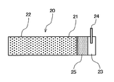
- FIG. 5 is a plan view schematically showing an example of the electrode (negative electrode) of the present invention.
- the electrode (negative electrode) 20 shown in FIG. 5 has an electrode mixture layer (negative electrode mixture layer) 21 on the surface of the current collector 22.
- a portion having the electrode mixture layer 21 (shown with dots in the drawing) is a main body portion.
- the electrode (negative electrode) 20 is provided with a tab portion 23 formed of an exposed portion where the electrode mixture layer is not formed on both surfaces of the current collector 22.
- the tab portion 23 is provided with a negative electrode tab 24 and a Li supply source 25. Note that the electrode main body shown in FIG. 5 is rectangular in plan view.
- the electrode (negative electrode) 20 of the present invention has a main body portion having an electrode mixture layer (negative electrode mixture layer) 21 on the surface of a current collector 22 and a tab portion.
- the tab portion 23 is provided at the right end of the electrode (negative electrode) 20, but may be provided near the center of the electrode (negative electrode) 20.
- a porous film composed of a resin such as polyolefin, polyester, polyimide, polyamide, polyurethane can be used.
- a resin such as polyolefin, polyester, polyimide, polyamide, polyurethane
- polyolefin is used. It is preferred to use a porous membrane made of
- polystyrene resin examples include polyethylene (PE) such as low density polyethylene, high density polyethylene, and ultrahigh molecular weight polyethylene; polypropylene (PP); etc., and only one of these may be used. You may use together.
- PE polyethylene
- PP polypropylene
- a porous film using two or more kinds of polyolefin for example, a porous film having a three-layer structure in which a PP layer is laminated on a PP layer via a PE layer can be mentioned.
- polyolefins those having a melting point, that is, a melting temperature measured by DSC of 80 to 150 ° C., in accordance with JIS K 7121 are preferably used.
- a porous film containing a polyolefin having such a melting point can be a separator having a shutdown characteristic starting temperature of 90 to 150 ° C. in which the polyolefin is softened and the pores of the separator are closed. By using the separator, it is possible to further improve the safety of the battery.
- porous membranes used in separators include ion-permeable porous membranes having a large number of pores formed by a conventionally known solvent extraction method, dry type or wet drawing method (generally used as battery separators). A microporous film) can be used.
- a laminated separator in which a heat-resistant porous layer containing a heat-resistant inorganic filler is formed on the surface of the porous film (microporous film) may be used.
- a stacked separator When such a stacked separator is used, the shrinkage of the separator is suppressed even when the temperature in the battery rises, and a short circuit due to contact between the positive electrode and the negative electrode can be suppressed. A high non-aqueous secondary battery can be obtained.
- boehmite As the inorganic filler to be contained in the heat-resistant porous layer, boehmite, alumina, silica, titanium oxide and the like are preferable, and one or more of these can be used.
- the heat-resistant porous layer preferably contains a binder for binding the inorganic fillers or bonding the heat-resistant porous layer and the microporous film.
- the binder includes an ethylene-vinyl acetate copolymer (EVA, having a structural unit derived from vinyl acetate of 20 to 35 mol%), an ethylene-acrylic acid copolymer such as an ethylene-ethyl acrylate copolymer, and a fluorine-based rubber.
- CMC carboxymethyl cellulose
- HEC hydroxyethyl cellulose
- PVA polyvinyl alcohol
- PVB polyvinyl butyral
- PVP polyvinyl pyrrolidone
- crosslinked acrylic resin polyurethane, epoxy resin, etc.
- the content of the inorganic filler in the heat-resistant porous layer is preferably 50% by volume or more in the entire volume of the components constituting the heat-resistant porous layer (in the entire volume excluding the pores), 70 It is more preferable that the volume is not less than volume%, and it is more preferable that the volume be not more than 99 volume% (the remainder may be the above binder).
- the thickness of the separator (a separator made of a microporous membrane made of polyolefin, or the laminated separator) is to reduce the occupancy of the battery internal volume of components that are not involved in the battery reaction and increase the amount of active material of the positive and negative electrodes From the viewpoint of increasing the design capacity and output density of the battery, it is preferably 30 ⁇ m or less, and more preferably 16 ⁇ m or less. However, from the viewpoint of sufficiently maintaining the strength of the separator, the thickness of the separator is preferably 5 ⁇ m or more, and more preferably 10 ⁇ m or more.
- the heat-resistant porous layer preferably has a thickness of 3 to 8 ⁇ m.
- the porosity of the heat resistant porous layer is preferably 40 to 70%.
- non-aqueous electrolyte solution for the non-aqueous electrolyte solution according to the battery of the present invention, a solution prepared by dissolving a lithium salt in the following non-aqueous solvent can be used.
- the solvent examples include ethylene carbonate (EC), propylene carbonate (PC), butylene carbonate (BC), dimethyl carbonate (DMC), diethyl carbonate (DEC), methyl ethyl carbonate (MEC), ⁇ -butyrolactone ( ⁇ - BL), 1,2-dimethoxyethane (DME), tetrahydrofuran (THF), 2-methyltetrahydrofuran, dimethyl sulfoxide (DMSO), 1,3-dioxolane, formamide, dimethylformamide (DMF), dioxolane, acetonitrile, nitromethane Aprotic such as methyl formate, methyl acetate, phosphoric acid triester, trimethoxymethane, dioxolane derivative, sulfolane, 3-methyl-2-oxazolidinone, propylene carbonate derivative, tetrahydrofuran derivative, diethyl ether, 1,3-propane sultone
- the organic solvent can be
- the lithium salt according to the non-aqueous electrolyte solution for example, LiClO 4, LiPF 6, LiBF 4, LiAsF 6, LiSbF 6, LiCF 3 SO 3, LiCF 3 CO 2, Li 2 C 2 F 4 (SO 3) 2, At least selected from LiN (CF 3 SO 2 ) 2 , LiC (CF 3 SO 2 ) 3 , LiC n F 2n + 1 SO 3 (n ⁇ 2), LiN (RfOSO 2 ) 2 [where Rf is a fluoroalkyl group] One type is mentioned.
- the concentration of these lithium salts in the non-aqueous electrolyte is preferably 0.6 to 1.8 mol / l, and more preferably 0.9 to 1.6 mol / l.
- Additives such as dinitrile, 1,3-propane sultone, diphenyl disulfide, cyclohexylbenzene, biphenyl, fluorobenzene, and t-butylbenzene can be added as appropriate.
- non-aqueous electrolyte a gel (gel electrolyte) obtained by adding a known gelling agent such as a polymer can be used.
- the lithium ion secondary battery of the present invention may be a flat or cylindrical steel can or aluminum can used as an outer can, or may be a soft package battery using a metal-deposited laminated film as an outer package. it can.
- Example 1 Preparation of positive electrode> LiCoO 2 as a positive electrode active material: 96.5 parts by mass, NMP solution containing PVDF as a binder at a concentration of 10% by mass: 20 parts by mass, and acetylene black as a conductive auxiliary agent: 1.5 parts by mass
- NMP was added to adjust the viscosity to prepare a positive electrode mixture-containing paste.
- this paste is intermittently applied to both sides of a rectangular aluminum foil having a plurality of through-holes and having a thickness of 15 ⁇ m while applying tension in the long side direction of the main body portion, and then dried to obtain aluminum.
- a positive electrode mixture layer is formed on one or both sides of the foil, and press treatment is continuously performed while applying tension in the long side direction of the main body so that the coating film density of the mixture layer is 3.80 g / cm 3.
- the thickness of the positive electrode mixture layer was adjusted, and the main body was cut so that the short side direction was 52 mm and the long side direction was 705 mm.
- a positive electrode tab (made of aluminum) was welded to the tab portion where the aluminum foil was exposed to produce a positive electrode having the same structure as that shown in FIG. 1 except for the size of each component.
- the positive electrode current collector is provided with through holes having a hole diameter of 150 ⁇ m in a staggered arrangement shown in FIG. 2 (hereinafter referred to as “pattern A”), and the positive electrode current collector has a porosity of 17%.
- the distance between one through hole 120 and the six through holes closest to the through hole 120 is 400 ⁇ m.
- two diagonal lines in the figure are 30 ° from the direction parallel to the short side of the main body, respectively, It arrange
- the average particle diameter D50% is 22 .mu.m, with d 002 is 0.338 nm, the graphite BET specific surface area is 3.8m 2 / g A (graphite no surface coating with amorphous carbon), the average particle diameter D50% is 10 [mu] m, with d 002 is 0.336 nm, the graphite BET specific surface area is 3.9m2 / g B (graphite covering the surface of the mother particle made of graphite with amorphous carbon), SiO 47.5: 47.5 is a composite in which the surface is coated with carbon (average particle size 8 ⁇ m, the amount of carbon in the composite is 20 mass%, hereinafter referred to as “SiO / carbon composite”).
- a water-based negative electrode mixture-containing paste was prepared by mixing with water.
- the negative electrode mixture-containing paste has a thickness of 10 ⁇ m and has a thickness of 10 ⁇ m, and is continuously applied intermittently while applying tension to the long side direction of the main body on both sides of the rectangular copper foil.
- a 300 ⁇ m thick Li foil (for Li pre-doping to the negative electrode) was pressure-bonded to the exposed tab portion of the copper foil to produce a negative electrode having the same structure as that shown in FIG. 5 except for the size of each component. .
- the negative electrode current collector is provided with through holes having a hole diameter of 150 ⁇ m in the pattern A arrangement (however, in FIG. 5, the through holes are shown in the tab portion 23 which is the exposed portion of the current collector 22).
- the porosity of the negative electrode current collector is 17%, and the distance between one through hole 120 and the six through holes closest to it is 180 ⁇ m.
- two diagonal lines in the figure are 30 ° from the direction parallel to the short side of the main body, respectively, It arrange
- ⁇ Preparation of separator> Add 5 kg of ion-exchanged water and 0.5 kg of a dispersant (aqueous polycarboxylic acid ammonium salt, solid content concentration 40%) to 5 kg of secondary aggregate boehmite, and use a ball mill for 20 hours with an internal volume of 20 L and a rotation speed of 40 times / minute for 10 hours.
- a dispersion was prepared by crushing treatment. The treated dispersion was vacuum-dried at 120 ° C. and observed by SEM. As a result, the shape of boehmite was almost plate-like. Further, when the average particle diameter (D50%) of boehmite was measured with a refractive index of 1.65 using a laser scattering particle size distribution analyzer (“LA-920” manufactured by HORIBA), it was 1.0 ⁇ m.
- a dispersant aqueous polycarboxylic acid ammonium salt, solid content concentration 40%
- PE microporous separator for lithium ion secondary battery [Porous layer (I): thickness 8 ⁇ m, porosity 40%, average pore diameter 0.02 ⁇ m, PE melting point 135 ° C.] on one side corona discharge treatment (discharge amount) 40 W ⁇ min / m 2 ) was applied, and the slurry a for forming the porous layer (II) was applied to the treated surface with a microgravure coater and dried to form a porous layer (II) to obtain a separator. The thickness of the porous layer (II) was adjusted to 4 ⁇ m. The boehmite content in the total volume of the constituent components of the porous layer (II) was 88% by volume.
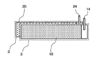
- FIG. 6 is a plan view schematically showing the arrangement of the positive electrode, the negative electrode, and the separator when the wound electrode body is manufactured.
- FIG. 6 is for demonstrating arrangement
- the positive electrode 10 and the negative electrode 20 were overlapped via the separator 3 (however, the porous layer (II) of the separator 3 was overlapped so as to face the positive electrode 10).
- the Li supply source of the negative electrode is not shown.
- the positive electrode 10, the negative electrode 20, and the separator 3 were wound in a spiral shape with the short electrode end on the left side in FIG. 6 as the winding core side, and further crushed into a flat shape to obtain a wound electrode body.
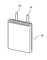
- a perspective view schematically showing the obtained wound electrode body is shown in FIG.
- the positive electrode tab 14 and the negative electrode tab 24 of the wound electrode body 30 are located on the outermost peripheral side of the wound electrode body.
- the said winding electrode body is inserted in the said hollow of the aluminum laminate film of thickness: 0.15mm, width: 61mm, and height: 68mm which formed the hollow so that the said winding electrode body might be accommodated, and on it
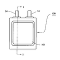
- FIG. 8 is a plan view schematically showing a lithium ion secondary battery
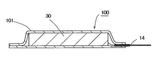
- FIG. 9 is a cross-sectional view taken along the line II of FIG.
- a lithium ion secondary battery 100 includes a wound electrode body in which a positive electrode and a negative electrode are laminated via a separator in an aluminum laminate film outer package 101 composed of two aluminum laminate films and wound in a spiral shape. 30 and a non-aqueous electrolyte (not shown) are accommodated, and the aluminum laminate film exterior body 101 is sealed by heat-sealing the upper and lower aluminum laminate films at the outer peripheral portion thereof.
- FIG. 9 in order to avoid making the drawing complicated, each layer constituting the aluminum laminate film outer package 101 and the positive electrode, the negative electrode and the separator constituting the wound electrode body are shown separately. Absent.
- the positive electrode tab 14 of the positive electrode and the negative electrode tab 24 of the negative electrode of the wound electrode body 30 are drawn out to the outside of the aluminum laminate film exterior body 101 so that they can be connected to an external device or the like.
- Example 2 The positive electrode current collector is provided with through holes having a hole diameter of 150 ⁇ m in the staggered arrangement shown in FIG. 3 (hereinafter referred to as “pattern B”), and the porosity is 17%. The distance between the through hole closest to this is changed to 380 ⁇ m, and the positive electrode current collector is changed from the direction in which the straight line indicated by the alternate long and short dash line in the figure is parallel to the short side of the main body portion.
- a positive electrode for a battery was produced in the same manner as in Example 1 except that the positive electrode for a battery was arranged so as to be at 0 °. And the lithium ion secondary battery was produced like Example 1 except having used the said battery positive electrode.
- Example 3 The positive electrode current collector is provided with through holes having a hole diameter of 150 ⁇ m in the parallel arrangement shown in FIG. 3 (hereinafter referred to as “pattern C”), and the porosity is 17%. The distance between the through hole closest to this is changed to 370 ⁇ m, and the two straight lines indicated by the alternate long and short dash line in the figure of this positive electrode current collector are parallel to the short side of the main body part, respectively.
- a positive electrode for a battery was produced in the same manner as in Example 1 except that it was disposed at 45 ° from the right direction. And the lithium ion secondary battery was produced like Example 1 except having used the said battery positive electrode.
- Example 4 The positive electrode current collector is provided with through holes having a hole diameter of 150 ⁇ m arranged in the pattern A, the porosity is 35%, and the distance between one through hole 120 and the closest through hole A positive electrode for a battery was produced in the same manner as in Example 1 except that the thickness was changed to 180 ⁇ m. And the lithium ion secondary battery was produced like Example 1 except having used the said battery positive electrode.
- Example 5 The direction of the negative electrode current collector is such that one of the three straight lines shown in FIG. 2 is parallel to the short side of the main body, and the other two are the short sides of the main body.
- a negative electrode for a battery was produced in the same manner as in Example 1 except that it was arranged at 30 ° from a direction parallel to the negative electrode.
- the lithium ion secondary battery was produced like Example 1 except having used the said negative electrode for batteries.
- Example 6 The positive electrode current collector is provided with through holes having a hole diameter of 150 ⁇ m arranged in the pattern A, the porosity is 50%, and the distance between one through hole 120 and the closest through hole A positive electrode for a battery was produced in the same manner as in Example 1 except that the thickness was changed to 100 ⁇ m. And the lithium ion secondary battery was produced like Example 1 except having used the said battery positive electrode.
- Example 7 The positive electrode current collector is provided with through holes having a hole diameter of 450 ⁇ m arranged in the pattern A, the porosity is 25%, and the distance between one through hole 120 and the closest through hole A positive electrode for a battery was produced in the same manner as in Example 1 except that the thickness was changed to 800 ⁇ m. And the lithium ion secondary battery was produced like Example 1 except having used the said battery positive electrode.
- Comparative Example 1 As for the direction of the positive electrode current collector, one of the three straight lines shown in FIG. 2 is parallel to the short side of the main body, and the other two are the short sides of the main body.
- a positive electrode for a battery was produced in the same manner as in Example 1 except that it was arranged at 30 ° from a direction parallel to the positive electrode.
- the lithium ion secondary battery was produced like Example 1 except having used the said battery positive electrode.
- Comparative Example 2 The positive electrode current collector is provided with through holes having a hole diameter of 350 ⁇ m arranged in the pattern A, the porosity is 17%, and the distance between one through hole 120 and the closest through hole A positive electrode for a battery was produced in the same manner as in Comparative Example 1 except that the thickness was changed to 900 ⁇ m. And the lithium ion secondary battery was produced like Example 1 except having used the said battery positive electrode.
- Comparative Example 3 A positive electrode for a battery was produced in the same manner as in Example 2 except that the direction of the positive electrode current collector was arranged so that the straight line indicated by the alternate long and short dash line in FIG. 3 was parallel to the short side of the main body. did. And the lithium ion secondary battery was produced like Example 1 except having used the said battery positive electrode.
- Comparative Example 4 In the direction of the positive electrode current collector, one of the two straight lines shown in FIG. 4 is a direction parallel to the short side of the main body, and the other one is the short side of the main body.
- a positive electrode for a battery was produced in the same manner as in Example 3, except that it was disposed at 90 ° from a direction parallel to the positive electrode.
- the lithium ion secondary battery was produced like Example 1 except having used the said battery positive electrode.
- Table 1 shows the configuration of the positive electrode current collector in each lithium ion secondary battery of Examples and Comparative Examples
- Table 2 shows the configuration of the negative electrode current collector
- Table 3 shows the evaluation results.
- the “angle” in Tables 1 and 2 is the angle from the direction parallel to the short side of the main body of the straight line between one through hole and the other through hole closest to the through hole (current collection). Angle from a direction parallel to the short side of the body).
- the lithium ion secondary batteries of Examples 1 to 7 using the positive electrode with the proper arrangement of the through-holes in the current collector are current collectors in the main body of the positive electrode after the charge / discharge cycle.
- the occurrence of breakage of the body was suppressed, and it had high reliability.
- the positive electrodes used in the lithium ion secondary batteries of Examples 1 to 7 the occurrence of breakage of the tab portion during welding of the positive electrode tab was well suppressed, but the average diameter of the through holes and the positive electrode current collector In the positive electrodes according to Examples 1 to 5 having more preferable porosity, the occurrence of cracks in the tab portion was well suppressed.
- the batteries of Comparative Examples 1 to 4 using the positive electrode in which the arrangement of the through holes in the current collector was inadequate were inferior in reliability because the positive electrode current collector was broken after the charge / discharge cycle.
- the positive electrode used in these batteries was inferior in reliability due to the occurrence of breakage in the current collector during welding during the production of the wound electrode body.
- the lithium ion secondary battery of the present invention can be applied to the same applications as various applications to which conventionally known lithium ion secondary batteries are applied.
Landscapes
- Chemical & Material Sciences (AREA)
- Engineering & Computer Science (AREA)
- Chemical Kinetics & Catalysis (AREA)
- Electrochemistry (AREA)
- General Chemical & Material Sciences (AREA)
- Manufacturing & Machinery (AREA)
- Power Engineering (AREA)
- Microelectronics & Electronic Packaging (AREA)
- Materials Engineering (AREA)
- Inorganic Chemistry (AREA)
- Secondary Cells (AREA)
Abstract
L'invention porte sur une électrode d'élément électrochimique hautement fiable et sur une batterie secondaire au lithium-ion ayant ladite électrode. L'électrode d'élément électrochimique selon la présente invention est utilisée pour une électrode positive ou une électrode négative d'un élément électrochimique ayant un corps d'électrode enroulé, et comprend : une section principale où une couche de mélange d'électrode contenant une matière active d'électrode est présente sur une surface ou sur les deux surfaces d'un collecteur de courant ; et une section de languette où la couche de mélange d'électrode est absente des deux surfaces du collecteur de courant. La section principale en vue en plan est un rectangle ayant une paire de côtés courts et une paire de côtés longs. Le collecteur de courant comporte de multiples trous traversants qui s'étendent d'une surface à l'autre surface, et les multiples trous traversants sont agencés régulièrement. Une ligne droite reliant un trou traversant à un autre trou traversant qui est le plus proche dudit trou traversant n'est pas présente dans la plage de 0° ± 20° par rapport à la direction parallèle au côté court de la section principale. La batterie secondaire au lithium-ion selon la présente invention a un corps d'électrode enroulé, et au moins l'électrode positive est l'électrode de dispositif électrochimique selon la présente invention.
Applications Claiming Priority (2)
| Application Number | Priority Date | Filing Date | Title |
|---|---|---|---|
| JP2016088348 | 2016-04-26 | ||
| JP2016-088348 | 2016-04-26 |
Publications (1)
| Publication Number | Publication Date |
|---|---|
| WO2017188021A1 true WO2017188021A1 (fr) | 2017-11-02 |
Family
ID=60160546
Family Applications (1)
| Application Number | Title | Priority Date | Filing Date |
|---|---|---|---|
| PCT/JP2017/015233 Ceased WO2017188021A1 (fr) | 2016-04-26 | 2017-04-14 | Électrode d'élément électrochimique et batterie secondaire au lithium-ion |
Country Status (1)
| Country | Link |
|---|---|
| WO (1) | WO2017188021A1 (fr) |
Cited By (6)
| Publication number | Priority date | Publication date | Assignee | Title |
|---|---|---|---|---|
| CN110462902A (zh) * | 2017-12-22 | 2019-11-15 | 株式会社Lg化学 | 用于锂金属电池的阳极和包括该阳极的锂金属电池 |
| WO2021085255A1 (fr) * | 2019-10-28 | 2021-05-06 | 株式会社村田製作所 | Électrode négative de batterie secondaire et batterie secondaire |
| WO2022142639A1 (fr) * | 2020-12-31 | 2022-07-07 | 华为技术有限公司 | Collecteur de courant négatif, son procédé de préparation, et batterie lithium métal |
| CN117393694A (zh) * | 2022-07-05 | 2024-01-12 | 东莞新能安科技有限公司 | 电化学装置和电子装置 |
| US12009522B2 (en) | 2017-12-22 | 2024-06-11 | Lg Energy Solution, Ltd. | Anode for lithium metal battery and lithium metal battery comprising the same |
| US12609405B2 (en) * | 2017-11-06 | 2026-04-21 | Lg Energy Solution, Ltd. | Electrode for secondary battery with improved safety, manufacturing method thereof, and secondary battery including same electrode |
Citations (5)
| Publication number | Priority date | Publication date | Assignee | Title |
|---|---|---|---|---|
| JPH1186869A (ja) * | 1997-09-01 | 1999-03-30 | Nippon Foil Mfg Co Ltd | 二次電池に用いる孔開き集電体 |
| JP2002110171A (ja) * | 2000-09-29 | 2002-04-12 | Sanyo Electric Co Ltd | 電池極板用の導電性芯体とこれを用いた電池 |
| JP2003282050A (ja) * | 2002-03-20 | 2003-10-03 | Ishikawajima Harima Heavy Ind Co Ltd | 電極及び電池 |
| JP2012238427A (ja) * | 2011-05-10 | 2012-12-06 | Gs Yuasa Corp | 電気化学装置および電気化学装置の製造方法 |
| WO2013005358A1 (fr) * | 2011-07-01 | 2013-01-10 | 株式会社豊田自動織機 | Appareil de stockage d'énergie et véhicule |
-
2017
- 2017-04-14 WO PCT/JP2017/015233 patent/WO2017188021A1/fr not_active Ceased
Patent Citations (5)
| Publication number | Priority date | Publication date | Assignee | Title |
|---|---|---|---|---|
| JPH1186869A (ja) * | 1997-09-01 | 1999-03-30 | Nippon Foil Mfg Co Ltd | 二次電池に用いる孔開き集電体 |
| JP2002110171A (ja) * | 2000-09-29 | 2002-04-12 | Sanyo Electric Co Ltd | 電池極板用の導電性芯体とこれを用いた電池 |
| JP2003282050A (ja) * | 2002-03-20 | 2003-10-03 | Ishikawajima Harima Heavy Ind Co Ltd | 電極及び電池 |
| JP2012238427A (ja) * | 2011-05-10 | 2012-12-06 | Gs Yuasa Corp | 電気化学装置および電気化学装置の製造方法 |
| WO2013005358A1 (fr) * | 2011-07-01 | 2013-01-10 | 株式会社豊田自動織機 | Appareil de stockage d'énergie et véhicule |
Cited By (10)
| Publication number | Priority date | Publication date | Assignee | Title |
|---|---|---|---|---|
| US12609405B2 (en) * | 2017-11-06 | 2026-04-21 | Lg Energy Solution, Ltd. | Electrode for secondary battery with improved safety, manufacturing method thereof, and secondary battery including same electrode |
| CN110462902A (zh) * | 2017-12-22 | 2019-11-15 | 株式会社Lg化学 | 用于锂金属电池的阳极和包括该阳极的锂金属电池 |
| CN110462902B (zh) * | 2017-12-22 | 2022-05-13 | 株式会社Lg化学 | 用于锂金属电池的阳极和包括该阳极的锂金属电池 |
| US12009522B2 (en) | 2017-12-22 | 2024-06-11 | Lg Energy Solution, Ltd. | Anode for lithium metal battery and lithium metal battery comprising the same |
| WO2021085255A1 (fr) * | 2019-10-28 | 2021-05-06 | 株式会社村田製作所 | Électrode négative de batterie secondaire et batterie secondaire |
| JPWO2021085255A1 (fr) * | 2019-10-28 | 2021-05-06 | ||
| JP7439834B2 (ja) | 2019-10-28 | 2024-02-28 | 株式会社村田製作所 | 二次電池用負極および二次電池 |
| US12597633B2 (en) | 2019-10-28 | 2026-04-07 | Murata Manufacturing Co., Ltd. | Negative electrode for secondary battery, and secondary battery |
| WO2022142639A1 (fr) * | 2020-12-31 | 2022-07-07 | 华为技术有限公司 | Collecteur de courant négatif, son procédé de préparation, et batterie lithium métal |
| CN117393694A (zh) * | 2022-07-05 | 2024-01-12 | 东莞新能安科技有限公司 | 电化学装置和电子装置 |
Similar Documents
| Publication | Publication Date | Title |
|---|---|---|
| JP5042400B2 (ja) | 非水二次電池 | |
| JP6253411B2 (ja) | リチウム二次電池 | |
| JP5464653B2 (ja) | 非水二次電池およびその製造方法 | |
| KR102419885B1 (ko) | 비수 전해질 이차 전지용 정극, 비수 전해질 이차 전지 및 그 시스템 | |
| CN107710465B (zh) | 非水电解质二次电池用负极活性物质、负极、二次电池以及负极材料的制造方法 | |
| JP5872055B2 (ja) | リチウム二次電池パック、並びにそれを用いた電子機器、充電システム及び充電方法 | |
| JP5489353B2 (ja) | 非水電解液二次電池 | |
| JP5945197B2 (ja) | 非水電解液二次電池 | |
| JP5121035B1 (ja) | リチウムイオン二次電池 | |
| JPWO2013038494A1 (ja) | リチウムイオン二次電池用電極、その製造方法およびリチウムイオン二次電池 | |
| JP5341280B2 (ja) | リチウム二次電池パック、並びにそれを用いた電子機器、充電システム及び充電方法 | |
| WO2017188021A1 (fr) | Électrode d'élément électrochimique et batterie secondaire au lithium-ion | |
| JP2013178913A (ja) | 非水電解液二次電池 | |
| JP2013145669A (ja) | 非水電解液二次電池 | |
| JP2017147054A (ja) | 非水電解質二次電池用正極および非水電解質二次電池 | |
| WO2014109366A1 (fr) | Batterie secondaire à électrolyte non aqueux | |
| KR20140041312A (ko) | 리튬 이온 이차 전지용 정극, 리튬 이온 이차 전지 및 전지 시스템 | |
| JP2019175657A (ja) | リチウムイオン二次電池。 | |
| JP2014022245A (ja) | リチウムイオン二次電池およびその製造方法 | |
| JP2014007010A (ja) | リチウム二次電池 | |
| JP5566825B2 (ja) | リチウム二次電池 | |
| JP2016170945A (ja) | 非水二次電池 | |
| JP2017098141A (ja) | リチウムイオン二次電池 | |
| JP6601951B2 (ja) | 非水二次電池 | |
| WO2017094526A1 (fr) | Électrode pour éléments électrochimiques, et pile rechargeable lithium-ion |
Legal Events
| Date | Code | Title | Description |
|---|---|---|---|
| NENP | Non-entry into the national phase |
Ref country code: DE |
|
| 121 | Ep: the epo has been informed by wipo that ep was designated in this application |
Ref document number: 17789307 Country of ref document: EP Kind code of ref document: A1 |
|
| 122 | Ep: pct application non-entry in european phase |
Ref document number: 17789307 Country of ref document: EP Kind code of ref document: A1 |
|
| NENP | Non-entry into the national phase |
Ref country code: JP |