WO2017188274A1 - Petit système de réacteur nucléaire avec commande de type à suivi de charge utilisant un fluide de refroidissement primaire de métal liquide - Google Patents
Petit système de réacteur nucléaire avec commande de type à suivi de charge utilisant un fluide de refroidissement primaire de métal liquide Download PDFInfo
- Publication number
- WO2017188274A1 WO2017188274A1 PCT/JP2017/016426 JP2017016426W WO2017188274A1 WO 2017188274 A1 WO2017188274 A1 WO 2017188274A1 JP 2017016426 W JP2017016426 W JP 2017016426W WO 2017188274 A1 WO2017188274 A1 WO 2017188274A1
- Authority
- WO
- WIPO (PCT)
- Prior art keywords
- reflector
- power generation
- generation system
- neutron
- core
- Prior art date
- Legal status (The legal status is an assumption and is not a legal conclusion. Google has not performed a legal analysis and makes no representation as to the accuracy of the status listed.)
- Ceased
Links
Images









Classifications
-
- G—PHYSICS
- G21—NUCLEAR PHYSICS; NUCLEAR ENGINEERING
- G21C—NUCLEAR REACTORS
- G21C1/00—Reactor types
- G21C1/02—Fast fission reactors, i.e. reactors not using a moderator ; Metal cooled reactors; Fast breeders
-
- G—PHYSICS
- G21—NUCLEAR PHYSICS; NUCLEAR ENGINEERING
- G21C—NUCLEAR REACTORS
- G21C11/00—Shielding structurally associated with the reactor
- G21C11/06—Reflecting shields, i.e. for minimising loss of neutrons
-
- G—PHYSICS
- G21—NUCLEAR PHYSICS; NUCLEAR ENGINEERING
- G21C—NUCLEAR REACTORS
- G21C3/00—Reactor fuel elements and their assemblies; Selection of substances for use as reactor fuel elements
- G21C3/02—Fuel elements
-
- G—PHYSICS
- G21—NUCLEAR PHYSICS; NUCLEAR ENGINEERING
- G21C—NUCLEAR REACTORS
- G21C3/00—Reactor fuel elements and their assemblies; Selection of substances for use as reactor fuel elements
- G21C3/42—Selection of substances for use as reactor fuel
- G21C3/58—Solid reactor fuel Pellets made of fissile material
- G21C3/60—Metallic fuel; Intermetallic dispersions
-
- G—PHYSICS
- G21—NUCLEAR PHYSICS; NUCLEAR ENGINEERING
- G21C—NUCLEAR REACTORS
- G21C7/00—Control of nuclear reaction
- G21C7/02—Control of nuclear reaction by using self-regulating properties of reactor materials, e.g. Doppler effect
-
- G—PHYSICS
- G21—NUCLEAR PHYSICS; NUCLEAR ENGINEERING
- G21C—NUCLEAR REACTORS
- G21C7/00—Control of nuclear reaction
- G21C7/06—Control of nuclear reaction by application of neutron-absorbing material, i.e. material with absorption cross-section very much in excess of reflection cross-section
- G21C7/08—Control of nuclear reaction by application of neutron-absorbing material, i.e. material with absorption cross-section very much in excess of reflection cross-section by displacement of solid control elements, e.g. control rods
- G21C7/10—Construction of control elements
-
- G—PHYSICS
- G21—NUCLEAR PHYSICS; NUCLEAR ENGINEERING
- G21C—NUCLEAR REACTORS
- G21C7/00—Control of nuclear reaction
- G21C7/28—Control of nuclear reaction by displacement of the reflector or parts thereof
-
- G—PHYSICS
- G21—NUCLEAR PHYSICS; NUCLEAR ENGINEERING
- G21C—NUCLEAR REACTORS
- G21C7/00—Control of nuclear reaction
- G21C7/30—Control of nuclear reaction by displacement of the reactor fuel or fuel elements
-
- G—PHYSICS
- G21—NUCLEAR PHYSICS; NUCLEAR ENGINEERING
- G21D—NUCLEAR POWER PLANT
- G21D3/00—Control of nuclear power plant
- G21D3/08—Regulation of any parameters in the plant
- G21D3/12—Regulation of any parameters in the plant by adjustment of the reactor in response only to changes in engine demand
-
- G—PHYSICS
- G21—NUCLEAR PHYSICS; NUCLEAR ENGINEERING
- G21D—NUCLEAR POWER PLANT
- G21D3/00—Control of nuclear power plant
- G21D3/08—Regulation of any parameters in the plant
- G21D3/12—Regulation of any parameters in the plant by adjustment of the reactor in response only to changes in engine demand
- G21D3/16—Varying reactivity
-
- Y—GENERAL TAGGING OF NEW TECHNOLOGICAL DEVELOPMENTS; GENERAL TAGGING OF CROSS-SECTIONAL TECHNOLOGIES SPANNING OVER SEVERAL SECTIONS OF THE IPC; TECHNICAL SUBJECTS COVERED BY FORMER USPC CROSS-REFERENCE ART COLLECTIONS [XRACs] AND DIGESTS
- Y02—TECHNOLOGIES OR APPLICATIONS FOR MITIGATION OR ADAPTATION AGAINST CLIMATE CHANGE
- Y02E—REDUCTION OF GREENHOUSE GAS [GHG] EMISSIONS, RELATED TO ENERGY GENERATION, TRANSMISSION OR DISTRIBUTION
- Y02E30/00—Energy generation of nuclear origin
-
- Y—GENERAL TAGGING OF NEW TECHNOLOGICAL DEVELOPMENTS; GENERAL TAGGING OF CROSS-SECTIONAL TECHNOLOGIES SPANNING OVER SEVERAL SECTIONS OF THE IPC; TECHNICAL SUBJECTS COVERED BY FORMER USPC CROSS-REFERENCE ART COLLECTIONS [XRACs] AND DIGESTS
- Y02—TECHNOLOGIES OR APPLICATIONS FOR MITIGATION OR ADAPTATION AGAINST CLIMATE CHANGE
- Y02E—REDUCTION OF GREENHOUSE GAS [GHG] EMISSIONS, RELATED TO ENERGY GENERATION, TRANSMISSION OR DISTRIBUTION
- Y02E30/00—Energy generation of nuclear origin
- Y02E30/30—Nuclear fission reactors
Definitions
- the present invention relates to a nuclear reactor system and structure for a small nuclear power generation system, and to a nuclear reactor structure incorporating a physical safety system instead of a conventional engineering safety system. That is, the present invention relates to a small nuclear reactor in which a load following control system in which a nuclear reaction in the nuclear reactor is naturally controlled is incorporated.
- a pressurized water reactor which is an indirect cycle nuclear reactor system, includes a steam generator and a heat exchanger between a primary cooling system and a secondary cooling system.
- a nuclear reactor used in this type of large-scale power generation system has a clad tube containing fuel formed by pelletizing a metal oxide containing uranium (U) 235 or plutonium (Pu) 239 having low heat transfer characteristics.
- a core with many fuel rods is provided.
- a core used for a large nuclear reactor is a set of about 200 bundles of fuel rods, each of which is a bundle of several tens of fuel rods, and controls the reaction rate of the fuel between these fuel rod assemblies. Control rods are arranged.
- An engineering safety system is indispensable in the current commercial nuclear reactor, so that it is inevitable that manufacturing and construction costs will increase.
- a safety system is basically indispensable in nuclear reactors using fission reactions.
- the engineering safety system always has a deficiency in safety, and there is a problem that the installation cost of the safety system becomes very high when aiming for a complete safety system.
- An object of the present invention is to construct a nuclear reactor system that employs a physical safety system instead of the above-described engineering safety system.
- Physical safety system means that the burnup of nuclear fuel is controlled based on natural phenomena in the reactor core. Natural phenomena in nuclear reactors include heat and neutron content. Among them, heat is a very important factor. There are structural materials, fuels, and the like as materials constituting the nuclear reactor, and these materials inevitably undergo thermal expansion or contraction due to heat. The nuclear reaction can be controlled by utilizing the phenomenon that the structural material is deformed by heat. The phenomenon will be specifically described below.
- Neutron flux generated from fissile materials such as Pu and U contained in fuel rods / fuel assemblies includes neutrons that leak outside the reactor and fuel There are two types of neutrons that are reabsorbed by the rod and contribute to fission.
- the proportion of neutrons leaking out of the system depends on the following parameters: (2-1) Reflector efficiency
- the neutron flux density in the core depends greatly on the reflection efficiency of the reflector surrounding the core, and the neutron multiplication factor K eff is set to 1 or more by using an efficient reflector. Is possible.
- a load following control method is possible.
- the coolant used in the present invention includes metal Na, lead (Pb) -bismuth (Bi), Pb, and Sn alone. Here, each characteristic will be described.
- the density of the metal Na depends on the temperature, and specifically depends on the coefficient of thermal expansion. As the temperature increases, the density decreases, so the probability of neutron leakage increases. As a result, the neutron multiplication factor K eff decreases and approaches 1, and when the temperature further increases, K eff becomes 1 or less, and the criticality of the reactor is maintained. It becomes impossible to do. Conversely, when the temperature decreases, the probability of neutron leakage decreases and K eff becomes 1 or more, and the fission chain reaction can be maintained.
- the amount of neutrons generated depends on the reactor volume, and the amount of neutron leakage depends on the reactor surface area. That is, the rate of leaking neutrons depends on the reactor surface area / volume ratio. As the surface area ratio increases, the ratio of leaking neutrons increases. On the other hand, the amount of neutrons generated also depends on the concentration of fissile Pu and U contained in the metal fuel rod.
- the nuclear reaction of the nuclear fuel constituting the reactor core can be controlled using the thermal characteristics as described above and the thermal deformation of the reflector due to the change in the amount of neutrons (Patent Document 1).
- the present invention relates to a core structure of a load following control type nuclear reactor loaded with a metal fuel rod assembly, and further, a load using thermal expansion of a liquid or gas such as a liquid metal having a thermal expansion coefficient larger than that of a solid.
- the present invention relates to the structure of a nuclear reactor incorporating a follow-up type control mechanism.
- the critical properties depend on the following factors: (1) Neutron flux (1-1) Neutron generation probability (1-2) Neutron leakage probability and reduction of leakage probability by reflector (1-3) Neutron absorption probability, neutron absorber and neutron flux (2) Fissile material Concentration (2-1) Fissile material concentration such as U or Pu in nuclear fuel rods (2-2) Substantial fissile material concentration by changing the distance between fuel assemblies
- the present invention is directed to a load following control type core. Specifically, it is intended for a mechanism in which the nuclear reactivity decreases due to a natural phenomenon when the core nuclear reactivity increases, and conversely, when the core nuclear reaction decreases, the nuclear reactivity increases due to a natural phenomenon.
- the natural phenomenon used here is the thermal expansion of the material.
- the structural material undergoes thermal expansion / contraction in response to changes in the core temperature.
- the nuclear reactivity is controlled by changing the fissionable substance concentration by utilizing the thermal expansion / contraction of the structural material and by changing the neutron flux.
- the reflector efficiency is changed by deformation of the reflector using the thermal expansion of the solid reflector support placed around the fuel assembly.
- a spiral / coiled support is attached to the support structure.
- liquid metal or gas is used as another method for increasing the amount of thermal expansion / contraction.
- the expansion coefficient includes a linear expansion coefficient ⁇ and a volume expansion coefficient ⁇ .
- FIG. 1 An example of a conversion mechanism based on this concept is shown in FIG.
- the piston 1 is inserted into the cylinder 2, and the reflector attaching jig 4 and the reflector fixing jig 5 are attached to the piston 1.
- MoS 2 molybdenum disulfide
- Cu copper
- graphite having a lubrication function and a leakage prevention function may be used as a lubricant. Good.
- a liquid metal tank 30 as shown in FIG. 1 is provided, and the volume of the member that expands by volume, that is, the capacity of the liquid metal or gas tank is increased, thereby increasing the amount of linear expansion. Can be bigger.
- the capacity of the tank 30 is V
- the cross-sectional area of the piston 1 is S
- the temperature difference is ⁇ t
- V is the sum of the liquid metal volume V1 in the cylinder and the liquid metal volume V2 in the attached tank.
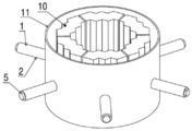
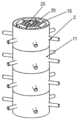
- FIG. 2 shows an example of a reflector moving mechanism in which a thermal expansion mechanism in which a piston and a cylinder as shown in FIG. 1 are installed is connected to a divisional reflector.
- the piston 1 is connected to the divisional reflector 10 via the reflector attachment jig 5, and the cylinder 2 is fixed to the reflector moving mechanism solid cylinder 11.
- the cylinder 2 is filled with liquid metal or gas.
- a bellows 15 is provided to prevent leakage of liquid metal or gas to the outside.
- examples of the gas include helium (He) and argon (Ar).
- examples of the material of the container include carbon (C), silicon carbide (SiC), silicon nitride (SiN), nickel steel, and tungsten steel.
- a reactor core including a plurality of fuel assemblies including a plurality of fuel rods in which a metallic fuel containing one or both of uranium (U) 235 and 238 and plutonium (Pu) 239 is sealed in a cladding tube;
- a nuclear reactor vessel containing the core;
- a primary coolant consisting of one of metallic sodium (Na), lead (Pb), tin (Sn) or lead-bismuth (Pb-Bi) filled in the reactor vessel and heated by the core;
- a neutron reflector disposed around the core for controlling a nuclear reaction of the core, a neutron reflector moving mechanism and / or a fuel assembly interval adjusting mechanism,
- the neutron reflector has a neutron reflection efficiency that keeps the core in a critical state while maintaining an effective multiplication factor of neutrons emitted from the core at 1 or more,
- the neutron reflector moving mechanism and the fuel assembly interval adjusting mechanism incorporate a liquid or gas having a larger expansion
- the reflector moving mechanism is coupled to the neutron reflector and changes the distance between the neutron reflector and the core by a displacement due to thermal expansion converted into the linear thermal expansion amount corresponding to the temperature in the reactor vessel.
- the fuel assembly interval adjusting mechanism is coupled to a member for setting the interval between the plurality of fuel assemblies in the core, and is based on thermal expansion converted into the linear thermal expansion amount corresponding to the temperature in the reactor vessel. By changing the distance between the fuel assemblies, the neutron effective multiplication factor is changed using this,
- a small nuclear power generation system including a small nuclear reactor capable of load-following control by temperature by the neutron reflector moving mechanism and / or the fuel assembly interval adjusting mechanism.
- the metallic fuel may be U-Pu-Zr ternary metallic fuel in which the total ratio of U235 and Pu239 is 20% or less.
- the mechanism for converting the volumetric thermal expansion of liquid or gas into linear thermal expansion includes a cylindrical container into which liquid or gas has been injected, and a piston that is inserted into the container so as to seal the liquid or gas. It can be set as the mechanism provided with the member.
- a bellows for preventing leakage of the liquid or gas may be attached between the cylindrical container and the piston-like member.
- molybdenum disulfide, copper, or graphite may be used as a lubricant having a lubricating function and a leakage preventing function in order to prevent leakage of the liquid or gas between the cylindrical container and the piston-shaped member.
- Liquids with a large expansion coefficient include lithium (Li), potassium (K), sodium (Na), mercury (Hg), lead (Pb), lead-bismuth (Pb-Bi), gallium (Ga), and zinc (Zn).
- the liquid metal selected from On the other hand, the gas can be helium (He) or argon (Ar).
- a tank having a larger capacity than the cylindrical container is coupled to the cylindrical container.
- a mechanism for converting a larger volumetric thermal expansion amount into a linear thermal expansion amount is coupled to the cylindrical container.
- a reflector moving mechanism fixed cylinder is arranged on the outer periphery of the substantially cylindrical neutron reflector that is divided into two or more in the circumferential direction surrounding the core.
- the cylindrical container or the cylindrical container and the tank sealed with a liquid or gas of a number equal to or greater than the number of divisions are coupled to the reflector moving mechanism fixed cylinder, and the cylindrical container or the cylindrical container and the tank.
- the neutron reflector is moved relative to the reflector moving mechanism fixed cylinder by a linear thermal expansion amount corresponding to a temperature change.
- the load following control is performed by controlling the distance between the neutron reflector and the fuel assembly.
- Another small nuclear power generation system of the present invention is coupled to each of the divided neutron reflectors inside the generally cylindrical neutron reflector divided into two or more in the circumferential direction surrounding the core.
- a plurality of cylindrical containers into which the piston-like members arranged radially from the center of the liquid tank are inserted, and a tank for liquid or gas is installed at the center of the plurality of cylindrical containers arranged radially.
- the liquid or gas is sealed in the plurality of cylindrical containers, and the neutron reflector is moved in the radial direction by the amount of linear thermal expansion corresponding to a temperature change, thereby separating the neutron reflector and the fuel assembly. To control the load.
- Another small nuclear power generation system of the present invention includes a plurality of ring-shaped reflections divided into two or more in the circumferential direction, further divided into two in the radial direction, and further divided into two or more in the height direction.
- the two ring-shaped reflectors of the outer ring-shaped reflector and the inner ring-shaped reflector are alternately shifted in the height direction so that they do not overlap when viewed from the side.
- a generally cylindrical neutron reflector that is disposed and generally surrounds the core,
- a cylindrical container having a piston-like member movable in the vertical direction, and a reflector moving mechanism comprising a tank in fluid communication with the cylindrical container;
- the piston-shaped member is fixed to the outer ring-shaped reflector group, the inner ring-shaped reflector group is fixed to the tank, and the cylinder-shaped container and the tank are sealed with liquid or gas,
- the outer ring-shaped reflector and the inner ring are moved in the vertical direction by the piston-like member by the amount of linear thermal expansion of the liquid or gas according to a temperature change.
- a slit is formed between each group of the reflectors, and the load follow-up control is performed by controlling the amount of neutron leakage by the interval of the slits.
- a plurality of the fuel assemblies are arranged substantially concentrically and divided into concentric groups, and a plurality of cylinders and tanks into which pistons are inserted include the fuel assemblies.
- the plurality of cylinders are arranged radially around the tank, the cylinder and the tank are in fluid communication with each other to be sealed with liquid or gas, and the piston is in the concentric group.
- the core is subjected to load following control by moving the concentric group of the fuel assembly in the radial direction by the amount of linear thermal expansion of the liquid or gas corresponding to a temperature change.
- the neutron reflector installed around the core is formed at a height smaller than the height of the core, and is moved from the lower side of the core toward the upper side or downward from the upper side by a moving mechanism. You may be comprised so that it can move toward the side.
- the neutron reflector having a length equivalent to the total length of the fuel assembly may be installed around the fuel assembly.
- the small nuclear power generation system of the present invention has a primary coolant natural circulation promotion function and a neutron around the fuel assembly in which the reflector moving mechanism or the fuel assembly interval adjustment function is attached in the reactor vessel.
- a metal cylinder having a leakage prevention function may be disposed, and a heat exchanger that performs heat exchange between the primary coolant and the secondary coolant may be disposed around the cylinder.
- a neutron absorber may be installed at the center of the fuel assembly.
- a neutron absorber may be installed outside the neutron reflector. Further, as the neutron absorber, a material suitable for treatment of radioactive waste or the like, such as an actinoid radioactive element, may be used.
- an alloy composed of Zr and U235, 238, and Pu239, or a metallic fuel composed of an alloy of Zr, U235, 238, and Pu, ferritic stainless steel, or chromium A plurality of fuel rods enclosed in a cladding tube made of molybdenum steel are provided.
- the reactor vessel according to the present invention is formed in a cylindrical shape having a diameter of 5 m or less and a height of 20 m or less, and the reactor core accommodated in the reactor vessel has a diameter of 5 to 15 mm and a length of 3.0 m or less. It consists of a plurality of fuel rods formed at the same time.
- the primary coolant heated by the nuclear reactor is supplied via a conduit, and supercritical carbon dioxide or subcritical dioxide heated by heat exchange with the primary coolant.
- a main heat exchanger in which the secondary coolant made of carbon, light water, or helium circulates, and the turbine power generation system driven by the secondary coolant heated by the main heat exchanger are connected to the outside of the nuclear reactor. It prepares for.
- the nuclear reactor is filled with the primary coolant, and is heated by the fuel in the reactor vessel and the primary coolant heated by the fuel in the reactor vessel.
- the turbine power generation system driven by the secondary coolant heated by the heat exchanger in the reactor vessel is provided outside the reactor.
- the secondary coolant may be mercury (Hg) or light water.
- the secondary coolant inlet pipe group may be connected to the first manifold, and the outlet pipe group may be connected to the second manifold.
- Another small nuclear power generation system of the present invention includes a core loaded with the fuel assembly to which the fuel assembly or the fuel assembly interval adjusting mechanism is attached at the center of the neutron reflector coupled to a moving mechanism.
- a plurality of tubes each having a thermoelectric generation element having a thermoelectric generation function on the inner surface are installed around the inside of the reactor, and a primary coolant is filled in the nuclear reactor and a secondary coolant is supplied to the plurality of tubes.
- thermoelectric generator is a filled scoop made of lead / tellurium (Pb—Te), silicon / germanium (Si—Ge), p-type La—Fe—Sb and n-type Ce—Co—Sb alloy.
- Pb—Te lead / tellurium
- Si—Ge silicon / germanium
- p-type La—Fe—Sb p-type Ce—Co—Sb alloy.
- Terdite-based, oxide-metal-based, p-type is composed of Ca-Co
- n-type is composed of oxide-based semiconductors composed of Ca and Mn oxides.
- the nuclear reactor for a small nuclear power generation system has a physical safety system called a neutron reflector moving mechanism or a fuel assembly interval adjusting mechanism using thermal expansion or contraction instead of the above-mentioned engineering safety system. Because it is adopted, a small and inexpensive nuclear reactor system can be provided.
- FIG. 1 is a perspective sectional view showing a neutron reflector moving mechanism according to the present invention.
- FIG. 2 is a schematic perspective view of a structure combining the neutron reflector and the moving mechanism according to the present invention.
- FIG. 3 is a perspective top view of an embodiment of the core of the small nuclear reactor of the present invention.
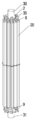
- FIG. 4 is a view showing the appearance of the fuel assembly.
- FIG. 5 is a graph showing the relationship between the average core radius and the effective multiplication factor of the fuel assembly according to the present invention.
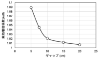
- FIG. 6 is a graph showing the relationship between the effective multiplication factor and the average gap between the core and the reflector according to the present invention.
- FIG. 7 is a view showing the external appearance of the fuel assembly and the interval adjusting mechanism according to the present invention.
- FIG. 8 is a top view of the fuel assembly interval adjusting mechanism according to the present invention.
- FIG. 9 is a graph showing the relationship between the effective multiplication factor and the average fuel assembly interval according to the present invention.
- FIG. 10 is a schematic perspective view showing the external appearance of the reflector moving mechanism with a liquid tank and the fuel assembly according to the present invention.
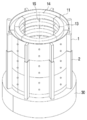
- FIG. 11A is a schematic perspective view of a cross section of an embodiment of a reflector slit adjusting reflector moving mechanism according to the present invention.
- FIG. 11B is a schematic perspective view of an embodiment of a reflector slit adjustment type reflector moving mechanism according to the present invention.
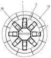
- FIG. 12 is a perspective plan view of an embodiment of the reflector-inside-type reflector moving mechanism according to the present invention.
- FIG. 13 is a cross-sectional view of a fuel assembly according to the present invention.
- FIG. 14 is a schematic perspective view showing the external appearance of the fuel assembly and reflector moving mechanism according to the present invention.
- FIG. 15 is a graph showing the difference in the operation time dependence of the effective multiplication factor in the nuclear power generation system according to the present invention depending on the presence or absence of a neutron absorber.
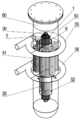
- FIG. 16A is a perspective view of a natural circulation nuclear power generation system provided with the in-core heat exchanger according to the present invention.
- FIG. 16B is a longitudinal sectional view of a natural circulation nuclear power generation system provided with the in-core heat exchanger according to the present invention.
- FIG. 17 is a schematic cross-sectional view showing an embodiment of a natural circulation nuclear power generation system according to the present invention.
- FIG. 18 is a schematic cross-sectional view showing another embodiment of the natural circulation nuclear power generation system according to the present invention.
- FIG. 19 is a schematic cross-sectional view showing an example of a split reflector natural circulation nuclear power generation system according to the present invention.
- FIG. 20 is a schematic cross-sectional view showing another embodiment of the division reflector-type small nuclear power generation system according to the present invention.
- FIG. 21 is a schematic cross-sectional view showing an embodiment of a supercritical carbon dioxide gas turbine small nuclear power generation system according to the present invention.
- FIG. 22 is a cross-sectional perspective view of an embodiment of a thermoelectric generator mechanism type small reactor according to the present invention.
- FIG. 23 is a schematic cross-sectional view showing an example of a small nuclear power generation system using mercury as the second coolant according to the present invention.
- the embodiment of the present invention is based on the result obtained by using a general nuclear calculation code SRAC (Standard Reactor Analysis Code).
- SRAC is a nuclear calculation code system that can be applied to core analysis of various types of nuclear reactors.
- the nuclear reaction was confirmed based on the basic specifications of the small nuclear reactor core shown below. (basic specifications) ⁇ Core diameter: 85cm, ⁇ Core height: 200cm ⁇ Fuel assembly: 60 bodies ⁇ Fuel pin diameter: 1 cm
- criticality calculation is performed on an example of a concrete reactor having a specific shape, and an example based on the result will be described with reference to the drawings.
- FIG. 3 shows a schematic cross-sectional structure of the small nuclear reactor according to the first embodiment of the present invention.
- the fuel assembly 20 is loaded into a nuclear reactor vessel made of a low alloy steel or the like, and the split neutron reflector 10 made of graphite is installed around the fuel assembly.
- the reflector can move from the bottom to the top or from the top to the bottom.
- a reflector moving mechanism fixed cylinder 11 is installed as a reflector support mechanism, and a liquid metal cylinder 2, a reflector fixing jig 5, and a piston 1 are attached thereto.
- This divisional reflector and reflector support mechanism are connected to a drive mechanism (not shown) installed in the upper part of the reactor.
- the present invention is not limited to this, and a reflector having a length equivalent to the entire length of the fuel assembly may be provided around the fuel assembly.
- the external appearance of the fuel assembly 20 is shown in FIG. Ferrite diameter stainless steel (HT-9 steel (Fe-12CHMo-V, W), which is one of the reference steels of ferritic steel materials), a 10mm diameter, long tube made of Pu-U-Zr alloy steel
- HT-9 steel Fe-12CHMo-V, W
- a 10mm diameter, long tube made of Pu-U-Zr alloy steel One fuel rod 21 produced by inserting a fuel pin having a thickness of 200 mm is bundled by using a spacer 22 to form a fuel assembly 20.
- the concentration of fissile material was 19% in total for Pu239 and U235.
- FIG. 5 shows the relationship between the core average dimension and the effective neutron magnification (K eff ).
- K eff tends to exceed 1.
- FIG. 6 shows the relationship between the average distance (gap) between the core and the reflector and the neutron multiplication factor (K eff ).
- K eff decreases as the reflector moves away from the fuel assembly, and conversely, K eff increases as the gap decreases.
- K eff can be controlled by utilizing the fact that the position of the reflector moves with temperature. That is, when the temperature of the core becomes high, the gap increases and the nuclear reactivity decreases, and when the temperature decreases, the gap decreases and the nuclear reactivity increases. That is, load following control is possible.
- FIG. 7 shows the appearance of the fuel assembly to which the fuel assembly position moving mechanism is attached.
- FIG. 8 is a plan view of a fuel assembly position moving mechanism that is attached to the upper and lower portions of the fuel assembly and that changes the distance between the fuel assembly core and the fuel assembly.
- the fuel assembly moving mechanism attaches the cylinder 2, the piston 1, the fuel assembly support 9, and the fuel assembly cooperation member 35 to the liquid tank 30 and the lower liquid tank 31.
- liquid metal candidates used in this example are gallium (Ga), mercury (Hg), zinc (Zn), cadmium (Cd), lead (Pb), lead-bismuth (Pb) that are liquid at temperatures up to 400 ° C. -Bi), potassium (K), sodium (Na), lithium (Li), tin (Sn).
- Ga gallium
- Hg mercury
- Zn zinc
- Cd cadmium
- Pb lead-bismuth
- K potassium
- Na sodium
- Li lithium
- Sn tin
- Hg, K, and Na are practically effective because they have a large coefficient of thermal expansion.
- FIG. 9 shows the relationship between the distance from the center fuel assembly of the fuel assembly at the outer edge of the core and the effective multiplication factor K eff . As can be seen from this figure, it can be seen that K eff decreases as the fuel assembly at the outer edge moves away from the center, and eventually becomes subcritical.
- FIG. 10 shows an embodiment of a reflector moving mechanism using both a liquid tank and a cylinder.
- the piston 1 and the reflector moving mechanism fixed cylinder 11 are attached to the division reflector 10.
- the liquid tank 30 is united with the cylinder 2 into which the piston 1 is inserted.
- the increase in the total liquid metal increases the rate of change of the reflector (movement amount / temperature difference).
- load following control becomes easy.
- FIGS. 11A and 11B show an embodiment in which the divided reflector is divided into two or more parts in the radial direction.
- the divided reflector in the radial direction is divided into an inner division reflector 14 and an outer division reflector 13.
- the inner division reflector 14 and the outer division reflector 13 are alternately shifted and overlapped in the height direction.
- the inner division reflector 14 is fixed to each other by the inner division reflector fixing jig 15.
- the outer division reflector 13 is coupled to the reflector moving mechanism fixed cylinder 11. Further, the reflector moving mechanism fixed cylinder 11 and the piston 1 are coupled.
- the cylinder 2 for inserting the piston 1 and the liquid tank 30 are integrated. Further, the inner division reflector 14 and the liquid tank 30 are fixed to each other although not shown.
- the outer divided reflector 13 is moved up and down by utilizing the thermal expansion of the metal filled in the liquid tank 30. Due to the movement caused by the liquid metal, a gap is formed between the inner division reflector 14 and the outer division reflector 13, and the reflection efficiency is lowered. By using this mechanism, load following control can be performed.
- FIG. 12 shows an embodiment of a reflector structure in which a reflector moving mechanism using a liquid is incorporated inside the reflector.
- a liquid metal such as Hg, K or Na is filled as the liquid.
- This embodiment is an example of an apparatus in which a reflector moving mechanism utilizing the thermal expansion of liquid metal is incorporated inside the reflector.
- a liquid metal moving mechanism is incorporated in the reflector 10 divided into eight.
- the liquid metal moving mechanism includes a liquid tank 30 at the center, and eight cylinders 2 into which the piston 1 is inserted are attached around the liquid tank 30.
- the piston 1 and the divisional reflector 10 are combined. By this mechanism, the reflector 10 moves to the outside as the liquid metal temperature rises, and the reflector moves to the inside as the temperature drops.
- the reflector structure of this embodiment is attached to the upper or lower part or both ends of the fuel assembly, it is difficult to move the reflector in the vertical direction, so the height of the reflector needs to be higher than the fuel assembly. It becomes.
- FIG. 13 shows a state in which the core having this structure is loaded on the reflector structure.
- the divided reflector 10 is loaded into the reflector moving mechanism fixed cylinder 11, and the cylinder 2 filled with the liquid metal is moved to the reflector moving mechanism fixed cylinder 11 in order to move the divided reflector 10 in the radial direction.
- the nuclear characteristics were investigated in this structure.
- a fuel assembly as shown in FIG.
- the excess reactivity in the initial process can be lowered by loading the neutron absorber 25 mixed with 20% or more high concentration B10 made of combustible neutron poison.
- a neutron poison such as gadolinium oxide (Gd 2 O 3 ) to the fuel rod.
- 16A and 16B show an embodiment of a nuclear reactor system in which the fuel assembly of the load following control system shown in FIG. 7 is installed in the reactor vessel.
- Pb—Bi is used as the primary coolant in the reactor vessel.
- Light water is used as the secondary coolant.
- the fuel assembly 20 is loaded into the reactor vessel 50.
- the fuel assembly 20 is connected to the cylinder 2 or the like coupled to the liquid tank 30, and the fuel is expanded by the expansion of Hg which is a liquid metal filled in the liquid tank 30. It is a mechanism that widens the interval between aggregates.
- a natural circulation promoting cylinder 52 is installed around the fuel assembly 20.
- the cylinder 52 has a chimney function and promotes natural circulation of the primary coolant.
- a heat exchanger 51 for exchanging heat between the primary coolant and the secondary coolant is installed around the reactor vessel 50.
- a plurality of secondary coolant inlet pipes of the heat exchanger are connected to the secondary coolant inlet manifold 56.
- the plurality of secondary coolant outlet pipes of the heat exchanger are connected to the secondary coolant outlet manifold 55.
- FIG. 17 shows an embodiment of a nuclear reactor system incorporating the nuclear reactor described in the seventh embodiment.
- the configuration inside the reactor vessel 50 is the same as that of the seventh embodiment.
- a fuel assembly moving mechanism, a natural circulation promoting cylinder 52, and a heat exchanger 51 in which the fuel assembly 20, the liquid tank 30, and the lower liquid tank 31 are main components, are incorporated.
- a secondary coolant inlet manifold 56 for inlet piping and a secondary coolant outlet manifold 55 for outlet piping of the heat exchanger are arranged around the reactor vessel 50.
- water is used as the secondary coolant.
- the pipe connected to the secondary coolant outlet manifold 55 is connected to the steam turbine 71 and drives this to generate electricity.
- the water returned to the water by the condenser 70 combined with the steam turbine 71 is preliminarily heated by the first heater 72 and the second heater 73, and then the coolant inlet manifold 56 is moved by the feed water pump 75.
- This embodiment generates steam directly in the heat exchanger 51 by heating the secondary coolant in the reactor vessel, removes this steam from the secondary coolant outlet manifold 55, and rotates the steam turbine. This is a system that generates electricity.
- the pressurizer 91 is used to suppress steam generation in the reactor vessel.
- the fuel assembly 20 the fuel assembly moving mechanism including the liquid metal tanks 30 and 31 as main components, and the heat exchanger 51 are incorporated.
- a natural circulation promoting cylinder 52 for promoting the natural circulation flow of the primary coolant is installed around the fuel assembly.
- Secondary coolant inlet manifold 56 for inlet piping and secondary coolant outlet manifold for outlet piping provided to absorb heat from the primary coolant (Bi-Pb) heated by natural circulation 55 is attached around the reactor vessel 50.
- water is used as the secondary coolant.
- the pipe connected to the secondary coolant outlet manifold 55 is connected to the main heat exchanger 90.
- the steam of the tertiary cooling water generated in the main heat exchanger 90 is connected to the steam turbine 71, and the turbine 71 is combined with the condenser 70 to drive the turbine and generate electric power.
- the tertiary cooling water that has been returned to water by the condenser 70 is preliminarily heated by the first heater 72 and the second heater 73 and then returned to the main heat exchanger 90 by the feed water pump 75.
- the secondary cooling water is supplied to the heat exchanger 51 in the reactor vessel 50 through the secondary coolant inlet manifold 56.
- the division reflector 10 is installed around the fuel assembly 20.
- This division reflector is controlled by utilizing expansion / contraction of the liquid metal stored in the liquid tank 30.
- a neutron absorption cylinder 67 is provided on the outer periphery of the split reflector for the purpose of preventing neutrons leaking from the reflector from returning to the core due to reflection.
- the structure in which the neutron absorption cylinder 67 and the divisional reflector are combined also has a function of promoting the primary coolant natural circulation.
- water is used as the secondary coolant.
- a plurality of heat exchangers 51 are installed in the reactor vessel 50. These heat exchangers 51 are connected to a secondary coolant inlet manifold 56 and a secondary coolant outlet manifold 55.
- the secondary coolant that has become steam in the heat exchanger 51 is sent to the turbine 71, and the steam returns to water in the condenser 70.
- the water is preliminarily heated by the first heater 72 and the second heater 73 and then supplied again to the heat exchanger 51 by the water supply pump 75.
- a divisional reflector moving mechanism 10 including a fuel assembly 20 and a liquid tank 30 as main components is incorporated in a reactor vessel 50.
- a primary coolant return pipe 57 and a primary coolant outlet pipe 58 are attached to the reactor vessel 50.
- water is used as the secondary coolant.
- the heated primary coolant is supplied from the primary coolant outlet pipe 58 to the main heat exchanger 90, and after the heat exchange, the primary coolant returns to the reactor vessel 50 through the return pipe 57.
- the steam generated in the main heat exchanger is connected to the steam turbine 71 and drives it to generate electricity.
- the water returned to the water by the condenser 70 combined with the steam turbine 71 is preliminarily heated by the first heater 72 and the second heater 73 and then supplied to the main heat exchanger 90 by the feed water pump 75. Is done.
- FIG. 21 Another embodiment of the system for circulating the primary coolant (Bi-Pb) will be described with reference to FIG.
- a divisional reflector moving mechanism 10 having a fuel assembly 20 and a liquid tank 30 as main components is incorporated in a nuclear reactor vessel 50.
- a primary coolant return pipe 57 and a primary coolant outlet pipe 58 are attached to the reactor vessel 50.
- supercritical carbon dioxide or subcritical carbon dioxide
- the primary coolant heated from the primary coolant outlet pipe 58 is supplied to the main heat exchanger 90, and after the heat exchange, the primary coolant returns to the reactor vessel 50 through the return pipe 57.
- Supercritical carbon dioxide (or subcritical carbon dioxide) gas heated in the main heat exchanger is connected to a supercritical carbon dioxide gas turbine 81 combined with a compressor 82 via an isolation valve 80, Drive to generate electricity.
- Supercritical carbon dioxide (or subcritical carbon dioxide) gas discharged from the gas turbine is cooled by the cooler 83 and then sent to the compressor 82.
- the low-temperature supercritical carbon dioxide gas is preliminarily heated by the regenerative heat exchanger 84 and then sent to the main heat exchanger 90 by the supercritical carbon dioxide (or subcritical carbon dioxide) gas supply pump 86.
- FIG. 22 shows an embodiment of a small nuclear reactor system in which a thermoelectric generator is incorporated in the nuclear reactor.
- a thermoelectric generator is an element that converts heat and electric power, and is an element that generates electromotive force due to the Seebeck effect when two different metals or semiconductors are joined together to give a temperature difference between the two ends. .
- a p-type semiconductor and an n-type semiconductor are used in combination. The following is given as a specific example (Non-Patent Document 3).
- thermoelectric generator tube using a thermoelectric generator using the Seebeck effect.
- the contents of this technique are described in Patent Document 2.
- Such tube-type thermoelectrons are incorporated into the reactor in the same manner as the heat exchanger tube.
- a plurality of fuel assemblies 20 are loaded into a nuclear reactor 50, and a liquid tank 30 and a cylinder 2 for controlling the interval between the fuel assemblies are arranged.
- a primary coolant natural circulation promotion cylinder 52 is disposed around the fuel assembly 20, and a neutron absorption cylinder 67 is disposed outside the primary coolant natural circulation promotion cylinder 52.
- An internal secondary coolant outlet manifold 65 is installed in the upper part of the reactor 50, and an internal secondary coolant inlet manifold 66 is installed in the lower part, and a tube-type thermoelectric power generation system 53 is installed between these manifolds.
- water or supercritical carbon dioxide gas was used as the secondary coolant.
- these materials since the material density is smaller than that of metal, there is a drawback that the heat transfer efficiency is small.
- the heat exchanger If a coolant having a low heat transfer coefficient efficiency is used, it is necessary to enlarge the heat transfer area, which is a serious problem. By using a coolant with high heat transfer efficiency, the heat transfer area can be reduced.
- mercury is employed as the secondary coolant.
- Non-Patent Document 3 Non-Patent Document 3
- Patent Document 3 Non-Patent Document 3
- FIG. 1 An embodiment of a small nuclear power generation system according to the present invention incorporating such a small mercury turbine will be described with reference to FIG.
- the reactor vessel 50 is filled with Pb—Bi as a primary coolant.
- a natural circulation promoting cylinder 52 is installed around the fuel assembly 20.
- a heat exchanger 51 is installed in the container, the inlet pipe of the heat exchanger is connected to the secondary coolant inlet manifold 56, and the outlet pipe is connected to the secondary coolant outlet manifold 55.
- Mercury as a secondary coolant heated in the core is supplied to the turbine 95.
- the turbine is connected to a mercury condenser 98.
- the condensed mercury is preliminarily heated by the mercury first heater 96 and then supplied to the reactor vessel 50 by the pump 97.
- Fuel assembly support 10 divisional reflectors, 11 Reflector moving mechanism fixed cylinder, 13 Outer division reflector, 14 Inner division reflector, 15 Bellows, 20 Fuel assembly, 21 Fuel rod, 24 fuel assembly support plate, 25 Neutron absorber rod, 30 liquid tank, 31 Lower liquid tank, 35 Fuel assembly linking member, 50 reactor vessel, 51 heat exchanger, 52 Natural circulation promotion cylinder, 53 Tube-type thermoelectric power generation system, 55 Secondary coolant outlet manifold, 56 Secondary coolant inlet manifold 57 Primary coolant return piping, 58 Primary coolant outlet piping, 65 internal secondary coolant outlet manifold, 66 Internal secondary coolant inlet manifold, 67 Neutron absorber tube, 70 condenser, 71 steam turbine, 72 first heater, 73 Second heater, 75 water supply pump, 76 Primary coolant circulation pump, 80 isolation valve, 81 supercritical carbon dioxide gas turbine, 82 compressor, 83 cooler, 84 Regenerative heat exchanger,
Landscapes
- Physics & Mathematics (AREA)
- Engineering & Computer Science (AREA)
- Plasma & Fusion (AREA)
- General Engineering & Computer Science (AREA)
- High Energy & Nuclear Physics (AREA)
- Chemical & Material Sciences (AREA)
- Chemical Kinetics & Catalysis (AREA)
- Dispersion Chemistry (AREA)
- Monitoring And Testing Of Nuclear Reactors (AREA)
Abstract
Priority Applications (6)
| Application Number | Priority Date | Filing Date | Title |
|---|---|---|---|
| CN201780014575.0A CN109074873B (zh) | 2016-04-26 | 2017-04-25 | 使用液态金属一次冷却剂的负载追随小型化核反应堆系统 |
| JP2018514637A JP6842191B2 (ja) | 2016-04-26 | 2017-04-25 | 液体金属一次冷却材を用いた負荷追随型制御小型原子炉システム |
| RU2018141105A RU2693861C1 (ru) | 2016-04-26 | 2017-04-25 | Система малогабаритного ядерного реактора, работающего в режиме следования за нагрузкой, использующая жидкометаллический теплоноситель первого контура |
| US16/096,228 US10991468B2 (en) | 2016-04-26 | 2017-04-25 | Load-following nuclear reactor system using thermal expansion-based neutron reflector movement and fuel assembly interval adjustment mechanisms and liquid metal primary coolant |
| EP17789556.2A EP3435383B1 (fr) | 2016-04-26 | 2017-04-25 | Petit système de réacteur nucléaire avec commande de type à suivi de charge utilisant un fluide de refroidissement primaire de métal liquide |
| CA3021942A CA3021942C (fr) | 2016-04-26 | 2017-04-25 | Petit systeme de reacteur nucleaire avec commande de type a suivi de charge utilisant un fluide de refroidissement primaire de metal liquide |
Applications Claiming Priority (2)
| Application Number | Priority Date | Filing Date | Title |
|---|---|---|---|
| JP2016087915 | 2016-04-26 | ||
| JP2016-087915 | 2016-04-26 |
Publications (1)
| Publication Number | Publication Date |
|---|---|
| WO2017188274A1 true WO2017188274A1 (fr) | 2017-11-02 |
Family
ID=60160850
Family Applications (1)
| Application Number | Title | Priority Date | Filing Date |
|---|---|---|---|
| PCT/JP2017/016426 Ceased WO2017188274A1 (fr) | 2016-04-26 | 2017-04-25 | Petit système de réacteur nucléaire avec commande de type à suivi de charge utilisant un fluide de refroidissement primaire de métal liquide |
Country Status (7)
| Country | Link |
|---|---|
| US (1) | US10991468B2 (fr) |
| EP (1) | EP3435383B1 (fr) |
| JP (1) | JP6842191B2 (fr) |
| CN (1) | CN109074873B (fr) |
| CA (1) | CA3021942C (fr) |
| RU (1) | RU2693861C1 (fr) |
| WO (1) | WO2017188274A1 (fr) |
Cited By (2)
| Publication number | Priority date | Publication date | Assignee | Title |
|---|---|---|---|---|
| JP2023538131A (ja) * | 2020-08-19 | 2023-09-06 | オクロ インコーポレイテッド | 容器内自然循環アルカリ金属炉システム、浄化システム、および関連付けられた方法 |
| JP2023549097A (ja) * | 2020-10-29 | 2023-11-22 | ウエスチングハウス・エレクトリック・カンパニー・エルエルシー | 炉心の出力を調整するためのデバイス、システム、及び方法 |
Families Citing this family (23)
| Publication number | Priority date | Publication date | Assignee | Title |
|---|---|---|---|---|
| US10141079B2 (en) | 2014-12-29 | 2018-11-27 | Terrapower, Llc | Targetry coupled separations |
| US11276503B2 (en) | 2014-12-29 | 2022-03-15 | Terrapower, Llc | Anti-proliferation safeguards for nuclear fuel salts |
| JP2018507396A (ja) | 2014-12-29 | 2018-03-15 | テラパワー, エルエルシー | 核物質処理 |
| US10867710B2 (en) | 2015-09-30 | 2020-12-15 | Terrapower, Llc | Molten fuel nuclear reactor with neutron reflecting coolant |
| MX391709B (es) | 2016-05-02 | 2025-03-21 | Terrapower Llc | Configuraciones mejoradas para enfriamiento y bombeo de reactor de combustible fundido. |
| EP3485496B1 (fr) | 2016-07-15 | 2020-04-15 | TerraPower, LLC | Réacteur nucléaire à segments verticaux |
| EP3497062B1 (fr) | 2016-08-10 | 2021-09-29 | TerraPower, LLC | Électrosynthèse de sels combustibles de chlorure d'uranium |
| US10923238B2 (en) | 2016-11-15 | 2021-02-16 | Terrapower, Llc | Direct reactor auxiliary cooling system for a molten salt nuclear reactor |
| CA3088265A1 (fr) | 2018-01-31 | 2019-08-08 | Terrapower, Llc | Echangeur de chaleur direct destine a un reacteur rapide a chlorure fondu |
| EP4297043A3 (fr) | 2018-03-12 | 2024-06-12 | TerraPower LLC | Ensemble réflecteur pour réacteur rapide à chlorure fondu |
| CN108630334B (zh) * | 2018-05-02 | 2023-04-11 | 北京卫星环境工程研究所 | 全环境的自然循环微型一体化反应堆 |
| WO2020060941A1 (fr) | 2018-09-14 | 2020-03-26 | Terrapower, Llc | Sel de liquide de refroidissement anticorrosion et procédé de fabrication associé |
| CN109872825A (zh) * | 2019-03-21 | 2019-06-11 | 路春雷 | 反应堆 |
| CN109841287B (zh) * | 2019-04-11 | 2023-04-11 | 哈尔滨工程大学 | 一种通过惯性力实现工作的液态燃料核反应堆 |
| CN111899903A (zh) * | 2019-05-05 | 2020-11-06 | 中国科学院理化技术研究所 | 液态金属反应堆、液态金属发电装置和液态金属换热装置 |
| CN110415839B (zh) * | 2019-07-23 | 2023-07-14 | 哈尔滨工程大学 | 一种基于可变结构的核反应堆控制装置 |
| CN112289473B (zh) * | 2019-07-24 | 2023-04-21 | 中国科学院理化技术研究所 | 一种热声发电系统 |
| CN110783004B (zh) * | 2019-10-22 | 2021-05-14 | 华南理工大学 | 一种高温球床堆铅基金属冷却剂及制备方法与换料方法 |
| CN110853774B (zh) * | 2019-11-21 | 2021-05-04 | 中国核动力研究设计院 | 一种氢化锆慢化金属冷却反应堆小型化设计方法及反应堆 |
| CA3162414A1 (fr) | 2019-12-23 | 2021-07-01 | Kent E. Wardle | Reacteurs a combustible en fusion et plaques annulaires a orifices pour reacteurs a combustible en fusion |
| US11728052B2 (en) | 2020-08-17 | 2023-08-15 | Terra Power, Llc | Fast spectrum molten chloride test reactors |
| CN114060167A (zh) * | 2021-11-16 | 2022-02-18 | 西安交通大学 | 一种双模式核动力推进装置及工作方法 |
| CN119560193B (zh) * | 2025-01-24 | 2025-07-04 | 上海交通大学 | 具备负载自主跟随功能的核储一体化铅基堆 |
Citations (3)
| Publication number | Priority date | Publication date | Assignee | Title |
|---|---|---|---|---|
| JPH01101497A (ja) * | 1987-10-15 | 1989-04-19 | Nippon Atom Ind Group Co Ltd | 固有安全原子炉 |
| JPH0815473A (ja) * | 1994-07-05 | 1996-01-19 | Toshiba Corp | 高速炉の反射体駆動装置 |
| WO2013094196A1 (fr) * | 2011-12-20 | 2013-06-27 | 日本ネイチャーセル株式会社 | Système compact de génération d'énergie nucléaire |
Family Cites Families (17)
| Publication number | Priority date | Publication date | Assignee | Title |
|---|---|---|---|---|
| BE476544A (fr) | 1946-02-20 | |||
| US3049483A (en) | 1952-03-28 | 1962-08-14 | Kenneth A Kesselring | Neutronic reactors and control means therefor |
| US3321371A (en) * | 1963-06-24 | 1967-05-23 | Hitachi Ltd | Nuclear reactor with pivotal reflector control arrangement |
| GB1102815A (en) * | 1964-06-02 | 1968-02-14 | Atomic Energy Authority Uk | Improvements in or relating to nuclear reactors |
| FR2665290B1 (fr) * | 1990-07-24 | 1994-06-10 | Toshiba Kk | Reacteur rapide. |
| JP4825763B2 (ja) * | 2007-09-21 | 2011-11-30 | 株式会社東芝 | 反射体制御方式の高速炉 |
| US8767902B2 (en) | 2010-02-22 | 2014-07-01 | Advanced Reactor Concepts LLC | Small, fast neutron spectrum nuclear power plant with a long refueling interval |
| US9183953B2 (en) * | 2010-05-25 | 2015-11-10 | Terrapower, Llc | Liquid fuel nuclear fission reactor |
| LT2758965T (lt) * | 2011-09-21 | 2017-11-10 | Armin HUKE | Dviejų skysčių reaktorius |
| US20140146934A1 (en) * | 2012-11-29 | 2014-05-29 | Robert M. Daily, III | Compact Liquid Metal Cooled Spherical Fast Neutron Reactor Core Design |
| US9899589B2 (en) | 2014-02-05 | 2018-02-20 | Panasonic Corporation | Thermal power generation unit and thermoelectric power generation system |
| RU158303U1 (ru) * | 2014-02-07 | 2015-12-27 | Российская Федерация, от имени которой выступает Государственная корпорация по атомной энергии "Росатом" | Ядерная энергетическая установка |
| KR101633493B1 (ko) * | 2014-07-24 | 2016-06-28 | 세종대학교산학협력단 | 다중 핵분열성층을 갖는 소형 모듈화 원자로 노심 및 이를 갖는 원자로 |
| KR101930615B1 (ko) | 2015-04-02 | 2018-12-18 | 가부시키가이샤 쿠리아 | 열 팽창 현상에 의한 반사체의 열 변형을 이용한 부하 추종형 소형 원자력 발전 시스템 |
| CN105023621B (zh) * | 2015-06-12 | 2017-11-10 | 陈安海 | 快堆型耦合核反应的实施方法及其核反应堆 |
| US10867710B2 (en) * | 2015-09-30 | 2020-12-15 | Terrapower, Llc | Molten fuel nuclear reactor with neutron reflecting coolant |
| US10014081B2 (en) * | 2015-11-01 | 2018-07-03 | Daniel Lee Laughman | Block-type movable reflector/moderator (RM) for nuclear reactor control |
-
2017
- 2017-04-25 WO PCT/JP2017/016426 patent/WO2017188274A1/fr not_active Ceased
- 2017-04-25 US US16/096,228 patent/US10991468B2/en active Active
- 2017-04-25 RU RU2018141105A patent/RU2693861C1/ru active
- 2017-04-25 CN CN201780014575.0A patent/CN109074873B/zh active Active
- 2017-04-25 EP EP17789556.2A patent/EP3435383B1/fr active Active
- 2017-04-25 CA CA3021942A patent/CA3021942C/fr active Active
- 2017-04-25 JP JP2018514637A patent/JP6842191B2/ja active Active
Patent Citations (3)
| Publication number | Priority date | Publication date | Assignee | Title |
|---|---|---|---|---|
| JPH01101497A (ja) * | 1987-10-15 | 1989-04-19 | Nippon Atom Ind Group Co Ltd | 固有安全原子炉 |
| JPH0815473A (ja) * | 1994-07-05 | 1996-01-19 | Toshiba Corp | 高速炉の反射体駆動装置 |
| WO2013094196A1 (fr) * | 2011-12-20 | 2013-06-27 | 日本ネイチャーセル株式会社 | Système compact de génération d'énergie nucléaire |
Cited By (5)
| Publication number | Priority date | Publication date | Assignee | Title |
|---|---|---|---|---|
| JP2023538131A (ja) * | 2020-08-19 | 2023-09-06 | オクロ インコーポレイテッド | 容器内自然循環アルカリ金属炉システム、浄化システム、および関連付けられた方法 |
| JP2024160346A (ja) * | 2020-08-19 | 2024-11-13 | オクロ インコーポレイテッド | 容器内自然循環アルカリ金属炉システム、浄化システム、および関連付けられた方法 |
| JP7843750B2 (ja) | 2020-08-19 | 2026-04-10 | オクロ インコーポレイテッド | 容器内自然循環アルカリ金属炉システム、浄化システム、および関連付けられた方法 |
| JP2023549097A (ja) * | 2020-10-29 | 2023-11-22 | ウエスチングハウス・エレクトリック・カンパニー・エルエルシー | 炉心の出力を調整するためのデバイス、システム、及び方法 |
| JP7854992B2 (ja) | 2020-10-29 | 2026-05-07 | ウエスチングハウス・エレクトリック・カンパニー・エルエルシー | 炉心の出力を調整するためのデバイス、システム、及び方法 |
Also Published As
| Publication number | Publication date |
|---|---|
| EP3435383A1 (fr) | 2019-01-30 |
| RU2693861C1 (ru) | 2019-07-05 |
| CA3021942A1 (fr) | 2017-11-02 |
| CN109074873B (zh) | 2023-07-25 |
| EP3435383B1 (fr) | 2021-01-20 |
| JPWO2017188274A1 (ja) | 2019-02-28 |
| US10991468B2 (en) | 2021-04-27 |
| JP6842191B2 (ja) | 2021-03-17 |
| EP3435383A4 (fr) | 2019-11-27 |
| US20190311816A1 (en) | 2019-10-10 |
| CA3021942C (fr) | 2021-04-06 |
| CN109074873A (zh) | 2018-12-21 |
Similar Documents
| Publication | Publication Date | Title |
|---|---|---|
| JP6842191B2 (ja) | 液体金属一次冷却材を用いた負荷追随型制御小型原子炉システム | |
| JP5967790B1 (ja) | 熱膨張現象による反射体の熱変形を利用した負荷追随型小型原子力発電システム | |
| CN113314240B (zh) | 一种空间堆热管理系统及工作方法 | |
| Forsberg et al. | Fluoride-salt-cooled high-temperature reactor (fhr) using british advanced gas-cooled reactor (agr) refueling technology and decay heat removal systems that prevent salt freezing | |
| CN109859859B (zh) | 一种基于钨导热的无对流换热整体模块式超小型空间反应堆堆芯 | |
| Du et al. | Reactor core design of UPR-s: a nuclear reactor for silence thermoelectric system NUSTER | |
| CN110211709A (zh) | 热管式碱金属转换一体化反应堆 | |
| US3031388A (en) | Fuel element for nuclear reactors | |
| Wu et al. | Conceptual design of a MW heat pipe reactor | |
| Zhang et al. | Conceptual design of heat pipe cooled reactor with liquid sodium core for space power systems | |
| CN117153433A (zh) | 一种基于控制环与反射层双重保护的空间反应堆控制方法 | |
| Xiong et al. | Design and performance analysis of high-power lead-bismuth cooled micro reactor | |
| Kovalchuk et al. | Revisiting the Choice of a Nuclear Power Source for the Arctic | |
| Zhang et al. | A conceptual design of a small modular natural-circulation liquid metal fast reactor with AMTEC units | |
| Guo et al. | Conceptual Design of 100 MW Natural Circulation Lead Cooled Fast Reactor Power System | |
| US2991980A (en) | Heat transfer means | |
| Choi et al. | Design and analysis of safety system using heat pipe of hybrid micro modular reactor (H-MMR) | |
| Crowell et al. | Conceptual Design of a Micro Nuclear Reactor for Canadian Arctic Applications | |
| Vrillon et al. | Space nuclear power studies in France.-A new concept of particle bed reactor | |
| Pitts et al. | RANKINE CYCLE SYSTEMS STUDIES FOR NUCLEAR SPACE POWER. | |
| Roberts et al. | A Heat-Pipe-Cooled Fast-Reactor Space Power Supply | |
| Sawada et al. | Long-life space reactor for photon propulsion | |
| Kima et al. | Preliminary Design Evaluation of IHTS-Combined Steam Generator Concepts for a Sodium-cooled Fast Reactor | |
| Tsvetkov et al. | Introductory design considerations | |
| Hub et al. | FEASIBILITY STUDY OF NUCLEAR STEAM SUPPLY SYSTEM USING 10,000-MW, SODIUM-COOLED BREEDER REACTOR. |
Legal Events
| Date | Code | Title | Description |
|---|---|---|---|
| WWE | Wipo information: entry into national phase |
Ref document number: 2018514637 Country of ref document: JP |
|
| WWE | Wipo information: entry into national phase |
Ref document number: 201780014575.0 Country of ref document: CN |
|
| ENP | Entry into the national phase |
Ref document number: 3021942 Country of ref document: CA |
|
| WWE | Wipo information: entry into national phase |
Ref document number: 2017789556 Country of ref document: EP |
|
| NENP | Non-entry into the national phase |
Ref country code: DE |
|
| ENP | Entry into the national phase |
Ref document number: 2017789556 Country of ref document: EP Effective date: 20181024 |
|
| 121 | Ep: the epo has been informed by wipo that ep was designated in this application |
Ref document number: 17789556 Country of ref document: EP Kind code of ref document: A1 |