WO2017188302A1 - Nœud de relais et terminal sans fil - Google Patents
Nœud de relais et terminal sans fil Download PDFInfo
- Publication number
- WO2017188302A1 WO2017188302A1 PCT/JP2017/016496 JP2017016496W WO2017188302A1 WO 2017188302 A1 WO2017188302 A1 WO 2017188302A1 JP 2017016496 W JP2017016496 W JP 2017016496W WO 2017188302 A1 WO2017188302 A1 WO 2017188302A1
- Authority
- WO
- WIPO (PCT)
- Prior art keywords
- information
- wireless terminal
- relay node
- base station
- enb
- Prior art date
- Legal status (The legal status is an assumption and is not a legal conclusion. Google has not performed a legal analysis and makes no representation as to the accuracy of the status listed.)
- Ceased
Links
Images







Classifications
-
- H—ELECTRICITY
- H04—ELECTRIC COMMUNICATION TECHNIQUE
- H04W—WIRELESS COMMUNICATION NETWORKS
- H04W36/00—Hand-off or reselection arrangements
- H04W36/24—Reselection being triggered by specific parameters
- H04W36/30—Reselection being triggered by specific parameters by measured or perceived connection quality data
- H04W36/305—Handover due to radio link failure
-
- H—ELECTRICITY
- H04—ELECTRIC COMMUNICATION TECHNIQUE
- H04B—TRANSMISSION
- H04B7/00—Radio transmission systems, i.e. using radiation field
- H04B7/24—Radio transmission systems, i.e. using radiation field for communication between two or more posts
- H04B7/26—Radio transmission systems, i.e. using radiation field for communication between two or more posts at least one of which is mobile
- H04B7/2603—Arrangements for wireless physical layer control
- H04B7/2606—Arrangements for base station coverage control, e.g. by using relays in tunnels
-
- H—ELECTRICITY
- H04—ELECTRIC COMMUNICATION TECHNIQUE
- H04L—TRANSMISSION OF DIGITAL INFORMATION, e.g. TELEGRAPHIC COMMUNICATION
- H04L1/00—Arrangements for detecting or preventing errors in the information received
- H04L1/12—Arrangements for detecting or preventing errors in the information received by using return channel
- H04L1/16—Arrangements for detecting or preventing errors in the information received by using return channel in which the return channel carries supervisory signals, e.g. repetition request signals
- H04L1/18—Automatic repetition systems, e.g. Van Duuren systems
-
- H—ELECTRICITY
- H04—ELECTRIC COMMUNICATION TECHNIQUE
- H04L—TRANSMISSION OF DIGITAL INFORMATION, e.g. TELEGRAPHIC COMMUNICATION
- H04L1/00—Arrangements for detecting or preventing errors in the information received
- H04L1/12—Arrangements for detecting or preventing errors in the information received by using return channel
- H04L1/16—Arrangements for detecting or preventing errors in the information received by using return channel in which the return channel carries supervisory signals, e.g. repetition request signals
- H04L1/18—Automatic repetition systems, e.g. Van Duuren systems
- H04L1/1812—Hybrid protocols; Hybrid automatic repeat request [HARQ]
-
- H—ELECTRICITY
- H04—ELECTRIC COMMUNICATION TECHNIQUE
- H04L—TRANSMISSION OF DIGITAL INFORMATION, e.g. TELEGRAPHIC COMMUNICATION
- H04L1/00—Arrangements for detecting or preventing errors in the information received
- H04L1/12—Arrangements for detecting or preventing errors in the information received by using return channel
- H04L1/16—Arrangements for detecting or preventing errors in the information received by using return channel in which the return channel carries supervisory signals, e.g. repetition request signals
- H04L1/18—Automatic repetition systems, e.g. Van Duuren systems
- H04L1/1812—Hybrid protocols; Hybrid automatic repeat request [HARQ]
- H04L1/1819—Hybrid protocols; Hybrid automatic repeat request [HARQ] with retransmission of additional or different redundancy
-
- H—ELECTRICITY
- H04—ELECTRIC COMMUNICATION TECHNIQUE
- H04W—WIRELESS COMMUNICATION NETWORKS
- H04W16/00—Network planning, e.g. coverage or traffic planning tools; Network deployment, e.g. resource partitioning or cells structures
- H04W16/24—Cell structures
- H04W16/26—Cell enhancers or enhancement, e.g. for tunnels, building shadow
-
- H—ELECTRICITY
- H04—ELECTRIC COMMUNICATION TECHNIQUE
- H04W—WIRELESS COMMUNICATION NETWORKS
- H04W40/00—Communication routing or communication path finding
- H04W40/02—Communication route or path selection, e.g. power-based or shortest path routing
- H04W40/22—Communication route or path selection, e.g. power-based or shortest path routing using selective relaying for reaching a BTS [Base Transceiver Station] or an access point
-
- H—ELECTRICITY
- H04—ELECTRIC COMMUNICATION TECHNIQUE
- H04W—WIRELESS COMMUNICATION NETWORKS
- H04W84/00—Network topologies
-
- H—ELECTRICITY
- H04—ELECTRIC COMMUNICATION TECHNIQUE
- H04W—WIRELESS COMMUNICATION NETWORKS
- H04W88/00—Devices specially adapted for wireless communication networks, e.g. terminals, base stations or access point devices
- H04W88/02—Terminal devices
- H04W88/04—Terminal devices adapted for relaying to or from another terminal or user
-
- B—PERFORMING OPERATIONS; TRANSPORTING
- B60—VEHICLES IN GENERAL
- B60L—PROPULSION OF ELECTRICALLY-PROPELLED VEHICLES; SUPPLYING ELECTRIC POWER FOR AUXILIARY EQUIPMENT OF ELECTRICALLY-PROPELLED VEHICLES; ELECTRODYNAMIC BRAKE SYSTEMS FOR VEHICLES IN GENERAL; MAGNETIC SUSPENSION OR LEVITATION FOR VEHICLES; MONITORING OPERATING VARIABLES OF ELECTRICALLY-PROPELLED VEHICLES; ELECTRIC SAFETY DEVICES FOR ELECTRICALLY-PROPELLED VEHICLES
- B60L2200/00—Type of vehicles
- B60L2200/26—Rail vehicles
-
- B—PERFORMING OPERATIONS; TRANSPORTING
- B61—RAILWAYS
- B61L—GUIDING RAILWAY TRAFFIC; ENSURING THE SAFETY OF RAILWAY TRAFFIC
- B61L15/00—Indicators provided on the vehicle or train for signalling purposes
- B61L15/0018—Communication with or on the vehicle or train
- B61L15/0027—Radio-based, e.g. using GSM-R
-
- H—ELECTRICITY
- H04—ELECTRIC COMMUNICATION TECHNIQUE
- H04L—TRANSMISSION OF DIGITAL INFORMATION, e.g. TELEGRAPHIC COMMUNICATION
- H04L1/00—Arrangements for detecting or preventing errors in the information received
- H04L1/08—Arrangements for detecting or preventing errors in the information received by repeating transmission, e.g. Verdan system
-
- H—ELECTRICITY
- H04—ELECTRIC COMMUNICATION TECHNIQUE
- H04W—WIRELESS COMMUNICATION NETWORKS
- H04W76/00—Connection management
- H04W76/20—Manipulation of established connections
- H04W76/28—Discontinuous transmission [DTX]; Discontinuous reception [DRX]
-
- H—ELECTRICITY
- H04—ELECTRIC COMMUNICATION TECHNIQUE
- H04W—WIRELESS COMMUNICATION NETWORKS
- H04W84/00—Network topologies
- H04W84/005—Moving wireless networks
-
- Y—GENERAL TAGGING OF NEW TECHNOLOGICAL DEVELOPMENTS; GENERAL TAGGING OF CROSS-SECTIONAL TECHNOLOGIES SPANNING OVER SEVERAL SECTIONS OF THE IPC; TECHNICAL SUBJECTS COVERED BY FORMER USPC CROSS-REFERENCE ART COLLECTIONS [XRACs] AND DIGESTS
- Y02—TECHNOLOGIES OR APPLICATIONS FOR MITIGATION OR ADAPTATION AGAINST CLIMATE CHANGE
- Y02D—CLIMATE CHANGE MITIGATION TECHNOLOGIES IN INFORMATION AND COMMUNICATION TECHNOLOGIES [ICT], I.E. INFORMATION AND COMMUNICATION TECHNOLOGIES AIMING AT THE REDUCTION OF THEIR OWN ENERGY USE
- Y02D30/00—Reducing energy consumption in communication networks
- Y02D30/70—Reducing energy consumption in communication networks in wireless communication networks
Definitions
- This disclosure relates to relay nodes and wireless terminals.
- Non-Patent Document 1 In 3GPP (3rd Generation Partnership Project), which is a standardization project for mobile communication systems, a relay node (RN) is specified (see Non-Patent Document 1).
- a relay node having the functionality of a base station can provide services to wireless terminals on behalf of the base station.
- relay nodes are mainly used to supplement the coverage of base stations.
- a relay node includes a control unit that establishes a connection with a wireless terminal and establishes a connection with a base station, a receiving unit that receives information of the wireless terminal from the base station, and the information A transmission unit that transmits to the wireless terminal.
- the receiving unit receives delivery confirmation information from the wireless terminal before transmitting the information.
- the delivery confirmation information indicates that the wireless terminal has received the information.
- the transmission unit stops transmitting the information to the wireless terminal in response to reception of the delivery confirmation information.
- a wireless terminal includes a control unit that establishes a connection with a relay node, a receiving unit that attempts to receive information on the wireless terminal from a base station to the relay node, and the information received from the base station.
- a transmission unit that transmits delivery confirmation information indicating that the wireless terminal has received the information to the relay node in response to successful reception.
- the relay node includes a control unit that establishes a connection with a wireless terminal, a receiving unit that receives information on the wireless terminal from a base station to the wireless terminal, and a transmission request for the information from the wireless terminal.
- a transmission unit that transmits the information to the wireless terminal only when receiving the information.
- a wireless terminal includes a control unit that establishes a connection with a base station and establishes a connection with a relay node, a receiving unit that receives information on the wireless terminal from the base station, and the receiving unit Includes a transmission unit that transmits a transmission request for the information to the relay node when reception of the information fails.
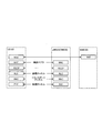
- FIG. 1 is a diagram illustrating a configuration of an LTE system.
- FIG. 2 is a protocol stack diagram of a radio interface in the LTE system.
- FIG. 3 is a protocol stack diagram of a radio interface in the LTE system.
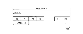
- FIG. 4 is a configuration diagram of a radio frame used in the LTE system.
- FIG. 5 is a block diagram of the UE 100.
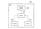
- FIG. 6 is a block diagram of the eNB 200.
- FIG. 7 is a block diagram of the RN 500.
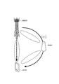
- FIG. 8 is a diagram for explaining the operating environment according to the first embodiment.
- FIG. 9 is a diagram for explaining the operating environment according to the first embodiment.
- FIG. 10 is a sequence diagram for explaining an operation (part 1) according to the first embodiment.
- FIG. 11 is a sequence diagram for explaining the operation (part 2) according to the first embodiment.
- FIG. 12 is a sequence diagram for explaining the operation (part 3) according to the first embodiment.
- FIG. 13 is a sequence diagram for explaining the operation (part 4) according to the first embodiment.
- FIG. 14 is a sequence diagram for explaining an operation according to the first modification of the first embodiment.
- FIG. 15 is a flowchart for explaining an operation according to the second modification of the first embodiment.
- FIG. 16 is a diagram for explaining an operating environment according to the second embodiment.
- FIG. 17 is a sequence diagram for explaining an operation according to the second embodiment.
- a relay node includes a control unit that establishes a connection with a wireless terminal and establishes a connection with a base station, a receiving unit that receives information of the wireless terminal from the base station, and the information A transmission unit that transmits to the wireless terminal.
- the reception unit may receive delivery confirmation information from the wireless terminal before transmitting the information.
- the delivery confirmation information may indicate that the wireless terminal has received the information.
- the transmission unit may transmit the information to the wireless terminal in response to reception of the delivery confirmation information.
- the transmission unit may transmit a retransmission request for the information to the base station when the reception unit fails to receive the information.
- the transmission unit may stop transmitting the retransmission request to the base station in response to reception of the delivery confirmation information, even when the reception unit has failed to receive the information. Good.
- the transmission unit may transmit identification information used for decoding the information to the wireless terminal.
- the identification information may be information assigned to the relay node by the base station.
- the transmission unit may transmit identification information used for decoding the information to both the wireless terminal and the base station.
- the identification information may be information assigned to the wireless terminal by the relay node.
- the transmission unit may transmit information on a period during which the relay node monitors a radio signal from the base station during discontinuous reception to the radio terminal.
- the receiving unit may receive control information from the base station.
- the control information may include resource information used for the relay node to transmit the information to the wireless terminal.
- a wireless terminal includes a control unit that establishes a connection with a relay node, a receiving unit that attempts to receive information on the wireless terminal from a base station to the relay node, and the information received from the base station.
- a transmission unit may be provided that transmits delivery confirmation information indicating that the wireless terminal has received the information to the relay node in response to successful reception.
- the receiving unit may receive identification information used for decoding the information from the relay node.
- the identification information may be information assigned to the relay node by the base station.
- the receiving unit may receive identification information used for decoding the information from the relay node.
- the identification information may be information assigned to the wireless terminal by the relay node.
- the reception unit may receive information on a period during which the relay node monitors a radio signal from the base station during discontinuous reception from the relay node.
- the receiving unit may receive control information from the base station.
- the control information may include resource information used for the relay node to transmit the information to the wireless terminal.
- the receiving unit may receive the information from the relay node based on the resource information.
- the relay node includes a control unit that establishes a connection with a wireless terminal, a receiving unit that receives information on the wireless terminal from a base station to the wireless terminal, and a transmission request for the information from the wireless terminal.
- a transmission unit that transmits the information to the wireless terminal only when receiving the information.
- the transmission unit may transmit delivery confirmation information indicating whether the relay node has received the information to the wireless terminal.
- a wireless terminal includes a control unit that establishes a connection with a base station and establishes a connection with a relay node, a receiving unit that receives information on the wireless terminal from the base station, and the receiving unit May include a transmission unit that transmits a transmission request for the information to the relay node when reception of the information fails.
- the transmission unit may transmit the transmission request only when the delivery confirmation information indicating that the relay node has received the information is received.
- the transmission unit may transmit a retransmission request for the information to the base station when the reception unit fails to receive the information.
- the transmission unit stops transmitting the retransmission request to the base station in response to reception of the information from the relay node even when the reception unit has failed to receive the information. May be.
- FIG. 1 is a diagram illustrating a configuration of an LTE system.
- the LTE system includes a UE (User Equipment) 100, an E-UTRAN (Evolved Universal Terrestrial Radio Access Network) 10, and an EPC (Evolved Packet Core) 20.
- UE User Equipment
- E-UTRAN Evolved Universal Terrestrial Radio Access Network
- EPC Evolved Packet Core
- the UE 100 corresponds to a wireless terminal.
- the UE 100 is a mobile communication device.
- UE100 can perform radio
- the E-UTRAN 10 corresponds to a radio access network.
- the E-UTRAN 10 includes an eNB (evolved Node-B) 200 and an RN (Relay Node) 500.
- eNB evolved Node-B
- RN Relay Node
- ENB 200 corresponds to a base station.
- the eNB 200 is connected to each other via the X2 interface.
- ENB 200 manages one or a plurality of cells.
- eNB200 performs radio
- the eNB 200 has a radio resource management (RRM) function, a routing function of user data (hereinafter also referred to as “data”), a measurement control function for mobility control / scheduling, and the like.
- RRM radio resource management
- Cell is used as a term indicating a minimum unit of a wireless communication area. “Cell” may also be used as a term indicating a function of performing wireless communication with the UE 100.
- RN500 corresponds to a relay device.
- the RN 500 can relay the data of the UE 100 between the UE 100 and the eNB 200.
- the RN 500 is wirelessly connected to the eNB 200 via the Un interface.
- the eNB 200 connected to the RN 500 for relay has a function of serving the RN 500.
- Such an eNB 200 is referred to as a DeNB (Donor eNB).
- the RN 500 corresponds to a relay node (relay device).
- the RN 500 can communicate with the UE 100 in place of the eNB 200.
- the RN 500 supports the functionality of the eNB 200. Accordingly, the RN 500 may terminate the radio protocols of the S1 and X2 interfaces and the E-UTRA (Evolved Universal Terrestrial Radio Access) radio interface.
- E-UTRA Evolved Universal Terrestrial Radio Access
- An S1 interface via the eNB 200 may be established between the RN 500 and the MME 300 / SGW 400. That is, the RN 500 may be connected to the MME 300 / SGW 400 via the S1 interface. The RN 500 may communicate with the MME 300 / SGW 400 via the S1 interface.
- An X2 interface via the eNB 200 may be established between the RN 500 and the eNB 200. That is, the RN 500 may be connected to the eNB 200 via the X2 interface. The RN 500 may communicate with the eNB 200 via the X2 interface.
- RN500 also supports a part (subset) of the functionality of UE100.
- the RN 500 includes a radio interface protocol to be described later in order to connect to the eNB 200 wirelessly (see FIG. 3).
- the EPC 20 corresponds to a core network. Further, the EPC 20 may constitute a network together with the E-UTRAN 10.
- the EPC 20 includes an MME (Mobility Management Entity) 300 and an SGW (Serving Gateway) 400.
- MME Mobility Management Entity
- SGW Serving Gateway
- the MME 300 performs various mobility controls for the UE 100, for example.
- the SGW 400 performs data transfer control.
- MME300 and SGW400 are connected with eNB200 via a S1 interface.
- MME300 and SGW400 may be connected with RN500 via an S1 interface.
- FIG. 2 and 3 are protocol stack diagrams of a radio interface in the LTE system.
- FIG. 2 shows a protocol stack diagram of a radio interface between the UE 100 and the eNB 200.
- FIG. 3 shows a protocol stack diagram of a radio interface between the RN 500 and the eNB 200.
- the radio interface protocol is divided into the first to third layers of the OSI reference model.
- the first layer is a physical (PHY) layer.
- the second layer includes a MAC (Medium Access Control) layer, an RLC (Radio Link Control) layer, and a PDCP (Packet Data Convergence Protocol) layer.
- the third layer includes an RRC (Radio Resource Control) layer.
- the physical layer performs encoding / decoding, modulation / demodulation, antenna mapping / demapping, and resource mapping / demapping.
- Data and control signals are transmitted between the physical layer of the UE 100 (RN 500) and the physical layer of the eNB 200 via a physical channel.
- the MAC layer performs data priority control, retransmission processing by hybrid ARQ (HARQ), random access procedure, and the like.
- Data and control signals are transmitted between the MAC layer of the UE 100 (RN 500) and the MAC layer of the eNB 200 via a transport channel.
- the MAC layer of the eNB 200 includes a scheduler (MAC scheduler). The scheduler determines the uplink / downlink transport format (transport block size, modulation / coding scheme (MCS)) and the resource blocks allocated to the UE 100.
- MCS modulation / coding scheme
- the RLC layer transmits data to the RLC layer on the receiving side using the functions of the MAC layer and the physical layer.
- Data and control signals are transmitted between the RLC layer of the UE 100 (RN 500) and the RLC layer of the eNB 200 via a logical channel.
- the PDCP layer performs header compression / decompression and encryption / decryption.
- the RRC layer is defined only in the control plane that handles control signals. Messages for various settings (RRC messages) are transmitted between the RRC layer of the UE 100 (RN 500) and the RRC layer of the eNB 200.
- the RRC layer controls the logical channel, the transport channel, and the physical channel according to establishment, re-establishment, and release of the radio bearer.
- RRC connection between the RRC of the UE 100 (RN 500) and the RRC of the eNB 200
- the UE 100 (RN 500) is in the RRC connected state.
- the UE 100 (RN 500) is in the RRC idle state.
- a NAS (Non-Access Stratum) layer located above the RRC layer performs, for example, session management and mobility management.
- FIG. 4 is a configuration diagram of a radio frame used in the LTE system.
- OFDMA Orthogonal Frequency Division Multiple Access
- SC-FDMA Single Carrier Frequency Division Multiple Access
- the radio frame is composed of 10 subframes arranged in the time direction.
- Each subframe is composed of two slots arranged in the time direction.
- the length of each subframe is 1 ms.
- the length of each slot is 0.5 ms.
- Each subframe includes a plurality of resource blocks (RB: Resource Block) in the frequency direction.
- Each subframe includes a plurality of symbols in the time direction.
- Each resource block includes a plurality of subcarriers in the frequency direction.
- One resource element (RE) is configured by one symbol and one subcarrier.
- radio resources time / frequency resources
- the section of the first several symbols of each subframe is an area that can be used as a physical downlink control channel (PDCCH: Physical Downlink. Control Channel) for transmitting a downlink control signal.
- the remaining part of each subframe is an area that can be used as a physical downlink shared channel (PDSCH) for transmitting downlink data.
- PDCH Physical Downlink control channel
- PDSCH physical downlink shared channel
- both ends in the frequency direction in each subframe are areas that can be used as physical uplink control channels (PUCCH: Physical Uplink Control Channels) for transmitting uplink control signals.
- PUCCH Physical Uplink Control Channels
- the remaining part of each subframe is an area that can be used as a physical uplink shared channel (PUSCH) for transmitting uplink data.
- PUSCH physical uplink shared channel
- FIG. 5 is a block diagram of the UE 100. As illustrated in FIG. 5, the UE 100 includes a receiver (receiver) 110, a transmitter (transmitter) 120, and a controller (controller) 130.
- the receiver 110 and the transmitter 120 may be an integrated transceiver (transmission / reception unit).
- the receiver 110 performs various types of reception under the control of the controller 130.
- the receiver 110 includes an antenna.
- the receiver 110 converts a radio signal received by the antenna into a baseband signal (received signal).
- the receiver 110 outputs a baseband signal to the controller 130.
- the transmitter 120 performs various transmissions under the control of the controller 130.
- the transmitter 120 includes an antenna.
- the transmitter 120 converts the baseband signal (transmission signal) output from the controller 130 into a radio signal.
- the transmitter 130 transmits a radio signal from the antenna.
- the controller 130 performs various controls in the UE 100.
- the controller 130 includes a processor and a memory.
- the memory stores a program executed by the processor and information used for processing by the processor.
- the processor includes a baseband processor and a CPU (Central Processing Unit).
- the baseband processor performs, for example, modulation / demodulation and encoding / decoding of a baseband signal.
- the CPU performs various processes by executing programs stored in the memory.
- the processor may include a codec that performs encoding / decoding of an audio / video signal.
- the processor executes various processes described later and various communication protocols described above.
- the UE 100 may include a GNSS (Global Navigation Satellite System) receiver.
- the GNSS receiver can receive a GNSS signal in order to obtain location information indicating the geographical location of the UE 100.
- the GNSS receiver outputs a GNSS signal to the controller 130.
- the UE 100 may have a GPS (Global Positioning System) function for acquiring location information of the UE 100.
- the process which at least any one of the receiver 110 with which UE100 is equipped, the transmitter 120, and the controller 130 performs may be demonstrated as a process (operation
- FIG. 6 is a block diagram of the eNB 200. As illustrated in FIG. 6, the eNB 200 includes a receiver (reception unit) 210, a transmitter (transmission unit) 220, a controller (control unit) 230, and a network interface 240.
- the transmitter 210 and the receiver 220 may be an integrated transceiver (transmission / reception unit).
- the receiver 210 performs various types of reception under the control of the controller 230.
- the receiver 210 includes an antenna.
- the receiver 210 converts a radio signal received by the antenna into a baseband signal (received signal).
- the receiver 210 outputs a baseband signal to the controller 230.
- the transmitter 220 performs various transmissions under the control of the controller 230.
- the transmitter 220 includes an antenna.
- the transmitter 220 converts the baseband signal (transmission signal) output from the controller 230 into a radio signal.
- the transmitter 220 transmits a radio signal from the antenna.
- the controller 230 performs various controls in the eNB 200.
- the controller 230 includes a processor and a memory.
- the memory stores a program executed by the processor and information used for processing by the processor.
- the processor includes a baseband processor and a CPU.
- the baseband processor performs, for example, modulation / demodulation and encoding / decoding of a baseband signal.
- the CPU performs various processes by executing programs stored in the memory.
- the processor executes various processes described later and various communication protocols described above.
- the network interface 240 is connected to the neighboring eNB 200 via the X2 interface.
- the network interface 240 is connected to the MME 300 and the SGW 400 via the S1 interface.
- the network interface 240 is used for communication performed on the X2 interface and communication performed on the S1 interface, for example.
- the process which at least any one of the transmitter 210 with which eNB200 is equipped, the receiver 220, the controller 230, and the network interface 240 performs is demonstrated as a process (operation
- FIG. 7 is a block diagram of the RN 500. As illustrated in FIG. 7, the RN 500 includes a receiver (reception unit) 510, a transmitter (transmission unit) 520, a controller (control unit) 530, and a network interface 540. The transmitter 510 and the receiver 520 may be an integrated transceiver (transmission / reception unit). The RN 500 may not include the network interface 540.
- the receiver 510 performs various types of reception under the control of the controller 530.
- Receiver 510 includes an antenna.
- the receiver 510 converts a radio signal received by the antenna into a baseband signal (received signal).
- the receiver 510 outputs a baseband signal to the controller 530.
- the transmitter 520 performs various transmissions under the control of the controller 530.
- Transmitter 520 includes an antenna.
- the transmitter 520 converts the baseband signal (transmission signal) output from the controller 530 into a radio signal.
- the transmitter 520 transmits a radio signal from the antenna.
- the controller 530 performs various controls in the RN 500.
- the controller 530 includes a processor and a memory.
- the memory stores a program executed by the processor and information used for processing by the processor.
- the processor includes a baseband processor and a CPU.
- the baseband processor performs, for example, modulation / demodulation and encoding / decoding of a baseband signal.
- the CPU performs various processes by executing programs stored in the memory.
- the processor executes various processes described later and various communication protocols described above.
- the network interface 540 is connected to another node (for example, another RN 500) provided in the mobile body.
- the RN 500 may perform communication with other nodes using the receiver 510 and / or the transmitter 520.
- the RN 500 may perform communication with other nodes using the receiver 510 and / or the transmitter 520 when the network interface 540 is not provided.
- processing executed by at least one of the transmitter 510, the receiver 520, the controller 530, and the network interface 540 included in the RN 500 will be described as processing (operation) executed by the RN 500 for convenience.
- FIGS. 8 and 9 are diagrams for explaining the operating environment according to the first embodiment.
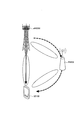
- the mobile body (for example, a train) 1 accommodates each UE 100. Further, the mobile body 1 is provided with an RN 500. Each UE 100 and RN 500 may establish a connection (RRC connection). Each UE 100 may be in an RRC connection state with respect to the RN 500. Each UE 100 and RN 500 may not have established a connection (RRC connection). Each UE 100 may be in an RRC idle state with respect to the RN 500. Each UE 100 may establish a connection (RRC connection) with the RN 500 as necessary.
- RRC connection connection
- RN 500 establishes connection (RRC connection) with eNB 200 (for example, macro eNB).
- the RN 500 may execute communication with the eNB 200 using a frequency of 4 GHz band, for example.
- the RN 500 may perform communication with the UE 100 using, for example, at least one of a frequency of 4 GHz band, 30 GHz band, and 70 GHz band.
- ENB200 is eNB installed in the circumference
- the moving body 1 is moving at high speed.
- the moving body 1 is moving at a speed (for example, 500 km / h) equal to or higher than a threshold. Therefore, each UE 100 and RN 500 is moving at a high speed (at a speed equal to or higher than a threshold).
- information on the UE 100 (for example, user data / packets) is sent from the eNB 200 to the UE 100 via the RN 500.
- the UE 100 can attempt to receive information on the UE 100 transmitted from the eNB 200 to the RN 500.
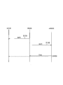
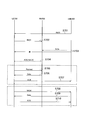
- FIG. 10 is a sequence diagram for explaining an operation (part 1) according to the first embodiment.
- FIG. 11 is a sequence diagram for explaining the operation (part 2) according to the first embodiment.
- the UE 100 can receive information on the UE 100 transmitted from the eNB 200 to the RN 500 by the following method.
- the RN 500 assigns identification information to the UE 100.
- the identification information is, for example, an identifier (RNTI: Radio Network Temporary Identifier) temporarily assigned to the UE 100.
- the identification information may be a cell identifier (C-RNTI: Cell-RNTI).
- C-RNTI Cell-RNTI
- the identification information may be an identifier that is individually assigned to the UE 100.
- the identification information may be an identifier indicating the RN 500 cell. Therefore, the identification information may be an identifier common to each UE 100 in the RN 500 cell.
- the identification information is used for decoding information (for example, data, control information for receiving data, etc.) of the UE 100 sent from the eNB 200 to the RN 500, as will be described later.
- the RN 500 may transmit control information (for example, information on radio resources allocated to the RN 500) for receiving information transmitted from the eNB 200 to each UE 100.
- control information for example, information on radio resources allocated to the RN 500
- the RN 500 transmits the identification information assigned to the UE 100 to the eNB 200.
- eNB200 encodes the information of UE100 transmitted to RN500 using the identification information received from RN500.
- the identification information is an identifier that is individually assigned to the UE 100
- the information of each UE 100 can be encoded using the identification information corresponding to the information of each UE 100.
- the eNB 200 transmits the encoded information (data) of the UE 100 to the RN 500.
- the direct transmission destination of the information of the UE 100 may be the RN 500. That is, the identifier of the transmission destination included in the information transmitted from the eNB 200 may be the identifier of the RN 500. Therefore, in the information on the UE 100, the direct transmission destination from the eNB 200 may not indicate the UE 100.
- the eNB 200 may transmit information of the plurality of UEs 100 as one data to the RN 500.
- UE100 tries to receive information from eNB200.
- UE100 decodes the received information using the identification information allocated from RN500.
- UE100 tries decoding, when the information from eNB200 may contain the information addressed to UE100 itself. For example, when the information from the eNB 200 is information addressed to the RN 500, the UE 100 attempts decoding. If the received information can be decoded, the UE 100 determines that the information has been successfully received. If the received information cannot be decoded, the UE 100 determines that reception of the information has failed.
- the UE 100 determines that the information has been successfully received when the information of the UE 100 itself can be decoded.
- the RN 500 receives information on the UE 100 from the eNB 200.
- the RN 500 decodes the received information addressed to the UE 100 using the identification information transmitted to the eNB 200.
- the RN 500 determines that the information has been successfully received. If the received information cannot be decoded, the UE 100 determines that reception of the information has failed.
- the RN 500 can relay (transmit) the received information on the UE 100 to the UE 100. As will be described later, when the RN 500 determines that the UE 100 has successfully received information from the eNB 200, the transmission (relay) of the information of the UE 100 may be omitted.
- the identification information is, for example, an identifier (RNTI: Radio Network Temporary Identifier) temporarily assigned to the RN 500.
- the identification information may be a cell identifier (C-RNTI: Cell-RNTI).
- C-RNTI Cell-RNTI
- the identification information may be an identifier that is individually assigned to the RN 500.
- the identification information may be an identifier that is individually assigned to the UE 100.
- the identification information may be an identifier common to each UE 100 in the RN 500 cell.
- step S202 the RN 500 transmits identification information to the UE 100.
- the UE 100 receives the identification information.
- Step S203 corresponds to step S103.
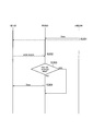
- FIG. 12 is a sequence diagram for explaining the operation (part 3) according to the first embodiment.
- step 301 corresponds to step S103 or S203.
- step S302 the UE 100 may transmit delivery confirmation information to the RN 500.
- the delivery confirmation information may indicate whether the UE 100 has received information from the eNB 200.
- the delivery confirmation information may indicate that the UE 100 has received information from the eNB 200 (ACK: Acknowledge).
- the delivery confirmation information may indicate that the UE 100 has not received information from the eNB 200 (NACK: Nackledge).
- the delivery confirmation information may include information indicating the content of information that has been successfully received.
- the delivery confirmation information may include information on a sequence number of a packet that has been successfully received.
- the delivery confirmation information may be information for requesting transmission (retransmission) of information to the RN 500.
- the delivery confirmation information may include information on a sequence number of a packet that has failed to be received.
- the UE 100 may transmit delivery confirmation information (ACK / NACK) in response to success or failure of reception of information from the eNB 200.
- UE100 may transmit delivery confirmation information (ACK) only when reception of information from eNB200 is successful.
- UE100 does not need to transmit delivery confirmation information (NACK), when reception of the information from eNB200 fails.
- the UE 100 can transmit the arrival confirmation information to the RN 500 before the RN 500 transmits the information from the eNB 200 to the UE 100.
- step S303 the RN 500 determines whether or not the UE 100 has received information from the eNB 200.
- the RN 500 may make a determination based on the delivery confirmation information. For example, the RN 500 may determine that the UE 100 has received information from the eNB 200 when receiving acknowledgment information indicating ACK (successful reception) before transmitting information from the eNB 200. On the other hand, RN 500 may determine that UE 100 has not received information from eNB 200 when receiving acknowledgment information indicating NACK (reception failure) before transmission of information from eNB 200.
- RN 500 may determine that UE 100 has not received information from eNB 200 when it does not receive delivery confirmation information even after a predetermined time has elapsed since reception of information from eNB 200.
- the predetermined time is, for example, the time from when the RN 500 receives information from the eNB 200 to before transmitting the information to the UE 100.
- the RN 500 may start a timer for measuring the predetermined time. The RN 500 may stop the timer in response to receiving the delivery confirmation information.
- RN500 performs the process of step S304, when UE100 is not receiving the information from eNB200 (when UE100 fails to receive the information from eNB200).
- the RN 500 ends the process. That is, the RN 500 omits the process of step S304.
- step S304 the RN 500 transmits information from the eNB 200 to the UE 100.
- the RN 500 may transmit (relay) the information to the UE 100 in response to receiving the delivery confirmation information indicating NACK (reception failure).
- the RN 500 may transmit (relay) the information to the UE 100.
- the RN 500 may stop transmitting (relaying) information from the eNB 200 in response to reception of delivery confirmation information indicating ACK (successful reception). Therefore, when the UE 100 succeeds in receiving information from the eNB 200, the RN 500 may stop transmitting information from the eNB 200. In other words, the RN 500 may not transmit information from the eNB 200 (the transmission of information from the eNB 200 may be omitted).
- UE100 can assist communication between eNB200 and RN500. For example, it is effective when the communication throughput between the eNB 200 and the RN 500 is reduced due to high-speed movement. Further, since the RN 500 can omit relaying information to the UE 100, the load on the RN 500 can be reduced.
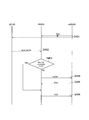
- FIG. 13 is a sequence diagram for explaining the operation (part 4) according to the first embodiment.
- step S401 corresponds to step S301.
- RN 500 has failed to receive information on UE 100 from eNB 200.
- Step S402 corresponds to step S302.
- the UE 100 can transmit the delivery confirmation information to the RN 500 before the RN 500 transmits the delivery confirmation information (step S404 or S406).
- the UE 100 may transmit the delivery confirmation information to the RN 500 at a timing earlier than the conventional transmission confirmation information transmission timing (for example, timing 4 ms after reception of the information). Since the transmission time interval (TTI: Transmission Time Interval) is shorter than before, the UE 100 may transmit the delivery confirmation information to the RN 500 before the RN 500 transmits the delivery confirmation information.
- TTI Transmission Time Interval
- the UE 100 may be able to transmit the delivery confirmation information to the RN 500 before the RN 500 transmits the delivery confirmation information.
- the RN 500 may be set by the eNB 200 to transmit the delivery confirmation information. Further, the RN 500 may notify (request) the eNB 200 of the timing for transmitting the delivery confirmation information.
- Step S403 corresponds to step S303.
- the RN 500 can transmit delivery confirmation information indicating a reception failure (NACK) of information from the eNB 200 to the eNB 200.
- the delivery confirmation information may be information requesting retransmission of information on the UE 100 that has already been transmitted from the eNB 200. Therefore, when both the RN 500 itself and the UE 100 fail to receive information from the eNB 200, the RN 500 can transmit delivery confirmation information indicating NACK to the eNB 200.
- the RN 500 executes the process of step S406.
- step S405 the eNB 200 retransmits the information (data) of the UE 100 to the RN 500 in response to receiving the delivery confirmation information indicating NACK.
- the RN 500 transmits (relays) the received UE100 information to the UE100.
- step S406 when the UE 100 succeeds in receiving information from the eNB 200, the RN 500 can transmit delivery confirmation information indicating successful reception (ACK) of information from the eNB 200 to the eNB 200. Therefore, even when RN 500 itself (receiver 210) fails to receive information from eNB 200, RN 500 sends a retransmission request (acknowledgment information indicating NACK) in response to reception of acknowledgment information indicating ACK. Transmission to the eNB 200 can be stopped.
- ACK delivery confirmation information indicating successful reception
- the UE 100 can assist communication between the eNB 200 and the RN 500. For example, it is effective when the communication throughput between the eNB 200 and the RN 500 is reduced due to high-speed movement.
- the RN 500 may transmit a retransmission request to the eNB 200 when the RN 500 itself fails to receive information from the eNB 200 regardless of whether or not the UE 100 has successfully received information from the eNB 200.
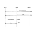
- FIG. 14 is a sequence diagram for explaining an operation according to the first modification of the first embodiment. Description of the same parts as described above will be omitted as appropriate.
- the UE 100 attempts to receive control information from the eNB 200.
- the eNB 200 transmits control information to the RN 500.
- the control information may include information for receiving information (data (user data)) of the UE 100 from the eNB 200 to the RN 500.
- the control information may include information for receiving information (data (user data)) of the UE 100 from the UE 100 to the eNB 200.
- the information for receiving information on the UE 100 may be, for example, resource information (time / frequency resource information) used for transmitting the information on the UE 100.
- Control information may be transmitted by PDCCH.
- RN 500 receives control information from eNB 200.
- the UE 100 attempts to receive control information. The description will proceed assuming that the UE 100 has successfully received the control information.
- control information is easier to receive than the user data because the coding rate is lower than that of the user data. Therefore, the UE 100 does not need to attempt to receive control information from the eNB 200 and to attempt to receive user data of the UE 100 from the eNB 200.
- UE100 may transmit the information for abbreviate
- Step S502 corresponds to step S103.
- UE100 may receive the information (user data) from eNB200 based on the control information from eNB200.
- the RN 500 transmits control information to the UE 100.
- the control information includes resource information used for transmitting information on the UE 100 from the RN 500 to the UE 100.
- the control information may be information included in the control information from the eNB 200.
- the UE 100 may stop receiving the receiver 110 until the process of step S504 is executed. For example, the UE 100 may stop receiving the receiver 110 until the UE 100 executes the process of step S504 after successful reception in step S501.
- the UE 100 may stop the reception of the receiver 110 by discontinuous reception (DRX: Discontinuous Reception). That is, the UE 100 may stop (stop) monitoring of control information from the RN 500.
- DRX Discontinuous Reception
- RN 500 may omit transmission of control information when UE 100 receives control information.
- step S504 the RN 500 transmits (relays) user data of the UE 100 to the UE 100 using the resource information included in the control information from the eNB 200.
- UE100 receives the user data of UE100 from RN500 using the resource information contained in the control information from eNB200.
- the UE 100 may stop the processes in steps S503 and S504 when the data reception is successful in step S502.
- the UE 100 can stop (stop) the monitoring of the control information from the RN 500 even when it is the transmission timing of the control information from the RN 500 by receiving the control information from the eNB 200.
- the power consumption of the UE 100 can be reduced.
- FIG. 15 is a flowchart for explaining an operation according to the second modification of the first embodiment. Description of the same parts as described above will be omitted as appropriate.
- the DRX timings of the UE 100 and the RN 500 coincide.
- the RN 500 transmits DRX information to the UE 100.
- the DRX information includes information on a period during which the RN 500 monitors a radio signal (particularly, information on the UE 100) from the eNB 200 during discontinuous reception (DRX).
- the DRX information may be information set in the RN 500 by the eNB 200.
- RN 500 may transmit DRX information in response to a request from UE 100.
- the RN 500 may transmit the DRX information determined by the RN 500 itself to the eNB 200.
- step S602 the UE 100 starts the DRX operation based on the DRX information. Therefore, the period during which the UE 100 and the RN 500 monitor (receive) a radio signal from the eNB 200 during discontinuous reception (DRX) coincides.
- the UE 100 can attempt to receive information on the UE 100 from the eNB 200 even during DRX.
- FIG. 16 is a diagram for explaining an operating environment according to the second embodiment.
- the UE 100 and the eNB 200 establish a connection (RRC connection).
- the UE 100 may be in an RRC idle state with respect to the eNB 200.
- the UE 100 may establish a connection (RRC connection) with the eNB 200 as necessary.
- the UE 100 may establish a connection (RRC connection) with the eNB 200.
- the RN 500 may be in an RRC idle state.
- the UE 100 may establish a connection (RRC connection) with the RN 500 as necessary.
- the RN 500 may establish a connection (RRC connection) with the eNB 200. Alternatively, the RN 500 may establish a connection (RRC connection) with the RN 500 as necessary.
- information for example, user data / packet
- the eNB 200 transmits information (for example, user data / packet) to the UE 100 without passing through the RN 500.
- the RN 500 can attempt to receive information on the UE 100 transmitted from the eNB 200 to the UE 100.
- the RN 500 may transmit (retransmit) information on the UE 100 to the UE 100.
- FIG. 17 is a sequence diagram for explaining an operation according to the second embodiment.
- the eNB 200 assigns identification information to the UE 100.
- the identification information is used to decode information from the eNB 200 to the UE 100.
- the identification information may be the same information (for example, C-RNTI) as in the first embodiment.
- step S702 the UE 100 transmits the identification information assigned from the eNB 200 to the RN 500.
- the RN 500 receives the identification information.
- the eNB 200 transmits information (data) of the UE 100 to the UE 100.
- the information on the UE 100 may be information encoded by identification information assigned to the UE 100.
- RN 500 tries to receive information of UE 100.
- the RN 500 decodes the received information using the identification information received from the UE 100.
- the RN 500 determines that the UE 100 has successfully received the information.
- the RN 500 determines that reception of the information of the UE 100 has failed.
- the UE 100 When the UE 100 receives the information of the UE 100 from the eNB 200, the UE 100 executes the process of step S707. On the other hand, when the UE 100 fails to receive the information of the UE 100, the following processing is executed.
- the description will proceed assuming that the UE 100 has failed to receive the information of the UE 100.
- the RN 500 may transmit delivery confirmation information to the RN 500.
- the delivery confirmation information may indicate whether or not the RN 500 has received information from the eNB 200.
- the delivery confirmation information may indicate that the RN 500 has received information from the eNB 200 (ACK).
- the acknowledgment information may indicate that the RN 500 has not received information from the eNB 200 (NACK). Similarly to the above, it may be the same information as the delivery confirmation information from the UE 100 to the RN 500.
- the RN 500 may transmit delivery confirmation information (ACK / NACK) in response to success or failure in receiving information from the eNB 200.
- the RN 500 may transmit the acknowledgment information (ACK) only when the information from the eNB 200 is successfully received.
- the RN 500 may not transmit the delivery confirmation information (NACK).
- the RN 500 may transmit delivery confirmation information (NACK) only when reception of information from the eNB 200 fails.
- the RN 500 may not transmit the delivery confirmation information (ACK).
- step S705 when RN500 has received the information from eNB200 successfully.
- step S706 when the RN 500 has failed to receive information from the eNB 200, the UE 100 executes the process of step S706.
- step S705 the UE 100 transmits a transmission request (retransmission request) for information on the UE 100 to the RN 500.
- the UE 100 itself fails to receive the information of the eNB 200, the UE 100 may transmit a retransmission request.
- the UE 100 may transmit a retransmission request to the RN 500 only when receiving acknowledgment information indicating ACK from the RN 500.
- the retransmission request may be the delivery confirmation information of the first embodiment described above.
- the RN 500 transmits information (data) of the UE 100 to the UE 100.
- the RN 500 transmits information (data) of the UE 100 to the UE 100.
- the RN 500 may transmit information on the UE 100 to the UE 100 only when a retransmission request is received.
- the RN 500 may transmit the information of the UE 100 to the UE 100 when the retransmission request is not received from the UE 100 even after a predetermined time has elapsed since the reception of the information from the eNB 200.
- UE100 receives the information of UE100 from RN500.
- step S707 the UE 100 transmits delivery confirmation information indicating ACK to the eNB 200.
- UE100 may transmit the delivery confirmation information which shows ACK to eNB200 according to reception of the information of UE100 from RN500, even if UE100 itself has failed in reception of the information of UE100.
- the UE 100 transmits a retransmission request to the eNB 200.
- the retransmission request may be delivery confirmation information indicating NACK.
- the eNB 200 retransmits information (data) of the UE 100.
- UE100 receives the information of UE100.
- UE100 transmits the delivery confirmation information which shows ACK to eNB200.
- the RN 500 can assist communication between the UE 100 and the eNB 200. For example, it is effective when the communication throughput between the UE 100 and the eNB 200 is reduced due to high-speed movement. Further, since the RN 500 can omit relaying information to the UE 100, the load on the RN 500 can be reduced.
- a plurality of RNs 500 may be installed in the moving body 1.
- An RN 500 may be installed in each of a plurality of vehicles (cargos) constituting the mobile body 1.
- an antenna of RN 500 may be installed at the top of each vehicle.
- UE 100 and RN 500 located in the same vehicle may perform communication (transmission and / or reception).
- Each RN 500 may execute communication (transmission and / or reception) with the eNB 200.
- one RN 500 (representative RN 500) may represent and execute communication with the eNB 200.
- the representative RN 500 may communicate with each other RN 500 (eg, via the network interface 540).
- the relay node may be a relay UE (ProSe UE-to Network Relay) that performs relay using a proximity service (ProSe: ProSe: Proximity-based Services).
- a relay UE ProSe UE-to Network Relay
- ProSe ProSe: Proximity-based Services
- a program for causing a computer to execute each process performed by any of the above-described nodes may be provided.
- the program may be recorded on a computer readable medium. If a computer-readable medium is used, a program can be installed in the computer.
- the computer-readable medium on which the program is recorded may be a non-transitory recording medium.
- the non-transitory recording medium is not particularly limited, but may be a recording medium such as a CD-ROM or a DVD-ROM.
- a chip configured by a memory that stores a program for executing each process performed by any one of the UE 100, the eNB 200, and the RN 500 and a processor that executes the program stored in the memory may be provided.
- the LTE system has been described as an example of the mobile communication system, but the present invention is not limited to the LTE system, and the content according to the present application may be applied to a system other than the LTE system.
- the present invention is useful in the communication field.
Landscapes
- Engineering & Computer Science (AREA)
- Computer Networks & Wireless Communication (AREA)
- Signal Processing (AREA)
- Mobile Radio Communication Systems (AREA)
- Communication Control (AREA)
- Mechanical Engineering (AREA)
Abstract
Selon un mode de réalisation de la présente invention, un nœud de relais comprend : une unité de commande conçue pour établir une connexion avec un terminal sans fil et une connexion avec une station de base ; une unité de réception conçue pour recevoir des informations du terminal sans fil provenant de la station de base ; et une unité de transmission conçue pour transmettre les informations au terminal sans fil. L'unité de réception reçoit des informations d'accusé de réception provenant du terminal sans fil avant de transmettre les informations. Les informations d'accusé de réception indiquent que les informations ont été reçues par le terminal sans fil. L'unité de transmission transmet les informations au terminal sans fil en réponse à la réception des informations d'accusé de réception.
Priority Applications (2)
| Application Number | Priority Date | Filing Date | Title |
|---|---|---|---|
| JP2018514657A JP6586515B2 (ja) | 2016-04-26 | 2017-04-26 | リレーノード及び無線端末 |
| US16/168,905 US10701610B2 (en) | 2016-04-26 | 2018-10-24 | Relay node and radio terminal |
Applications Claiming Priority (2)
| Application Number | Priority Date | Filing Date | Title |
|---|---|---|---|
| JP2016-088308 | 2016-04-26 | ||
| JP2016088308 | 2016-04-26 |
Related Child Applications (1)
| Application Number | Title | Priority Date | Filing Date |
|---|---|---|---|
| US16/168,905 Continuation US10701610B2 (en) | 2016-04-26 | 2018-10-24 | Relay node and radio terminal |
Publications (1)
| Publication Number | Publication Date |
|---|---|
| WO2017188302A1 true WO2017188302A1 (fr) | 2017-11-02 |
Family
ID=60159685
Family Applications (1)
| Application Number | Title | Priority Date | Filing Date |
|---|---|---|---|
| PCT/JP2017/016496 Ceased WO2017188302A1 (fr) | 2016-04-26 | 2017-04-26 | Nœud de relais et terminal sans fil |
Country Status (3)
| Country | Link |
|---|---|
| US (1) | US10701610B2 (fr) |
| JP (1) | JP6586515B2 (fr) |
| WO (1) | WO2017188302A1 (fr) |
Cited By (1)
| Publication number | Priority date | Publication date | Assignee | Title |
|---|---|---|---|---|
| JP2023538797A (ja) * | 2020-06-19 | 2023-09-12 | コーニンクレッカ フィリップス エヌ ヴェ | サイドリンク中継におけるフィードバック及びトラフィックの区別 |
Families Citing this family (4)
| Publication number | Priority date | Publication date | Assignee | Title |
|---|---|---|---|---|
| US11765723B2 (en) * | 2019-10-11 | 2023-09-19 | Qualcomm Incorporated | Scheduling via wireless communication relay |
| WO2021095181A1 (fr) * | 2019-11-13 | 2021-05-20 | 株式会社Nttドコモ | Terminal et procédé de communication sans fil |
| JPWO2024166337A1 (fr) | 2023-02-09 | 2024-08-15 | ||
| WO2024166334A1 (fr) | 2023-02-09 | 2024-08-15 | 本田技研工業株式会社 | Station de base sans fil, dispositif relais sans fil, corps mobile, système de communication sans fil, procédé de communication sans fil et programme |
Citations (4)
| Publication number | Priority date | Publication date | Assignee | Title |
|---|---|---|---|---|
| JP2010263297A (ja) * | 2009-04-30 | 2010-11-18 | Ntt Docomo Inc | 無線中継局 |
| JP2011509052A (ja) * | 2008-01-02 | 2011-03-17 | インターデイジタル テクノロジー コーポレーション | 協調無線通信(cooperativewirelesscommunications)のための方法および装置 |
| JP2012074757A (ja) * | 2009-01-27 | 2012-04-12 | Sharp Corp | 基地局装置、リレー局装置、接続処理方法 |
| JP2014225859A (ja) * | 2013-04-22 | 2014-12-04 | 矢崎総業株式会社 | 通信システム及び通信ノード |
Family Cites Families (26)
| Publication number | Priority date | Publication date | Assignee | Title |
|---|---|---|---|---|
| JP4690260B2 (ja) * | 2006-07-10 | 2011-06-01 | Necインフロンティア株式会社 | 無線通信システム、無線基地局、通信制御方法、および通信制御プログラム |
| US8402335B2 (en) * | 2007-06-22 | 2013-03-19 | Nokia Corporation | Status report messages for multi-layer ARQ protocol |
| US8270369B1 (en) * | 2007-11-16 | 2012-09-18 | Marvell International Ltd. | Service data unit discard system for radio access networks |
| US8332704B2 (en) * | 2008-03-14 | 2012-12-11 | Samsung Electronics Co., Ltd. | Apparatus and method for supporting automatic retransmission request (ARQ) in a wireless relay communication system |
| EP2134116A1 (fr) * | 2008-06-11 | 2009-12-16 | Mitsubishi Electric R&D Centre Europe B.V. | Procédé et dispositif pour identifier au moins un terminal dont les signaux sont transférés vers au moins un terminal et station de base qui doit être retransmise par un relais |
| US8761059B2 (en) * | 2008-10-10 | 2014-06-24 | Lg Electronics Inc. | Method for transmitting relay node-specific control channel |
| MX2011007655A (es) * | 2009-01-20 | 2011-08-24 | Fujitsu Ltd | Sistema de radiocomunicacion. |
| US8537724B2 (en) * | 2009-03-17 | 2013-09-17 | Motorola Mobility Llc | Relay operation in a wireless communication system |
| KR101611300B1 (ko) * | 2009-04-21 | 2016-04-11 | 엘지전자 주식회사 | 전송 지시자를 이용한 중계기 통신 기법 |
| CA2765663C (fr) * | 2009-06-19 | 2017-06-06 | Research In Motion Limited | Transmissions en liaison montante pour relais de type 2 |
| US20110164577A1 (en) * | 2010-01-06 | 2011-07-07 | Research In Motion Limited | Intra-Donor Cell Coordinated Multi-Point Transmission with Type 1 Relay |
| JP5883802B2 (ja) * | 2010-02-22 | 2016-03-15 | 中国移▲動▼通信集▲団▼公司China Mobile Communications Corporation | eMBMSサービスをサポートする方法、MCCH修正通知送信方法及びデバイス |
| KR101829832B1 (ko) * | 2010-03-26 | 2018-02-19 | 엘지전자 주식회사 | 무선 통신 시스템에서 신호 송수신 방법 및 이를 위한 장치 |
| US8620302B2 (en) * | 2010-04-02 | 2013-12-31 | Telefonaktiebolaget Lm Ericsson (Publ) | Configuring relay cell identities in cellular networks |
| WO2013113013A2 (fr) * | 2012-01-27 | 2013-08-01 | Futurewei Technologies, Inc. | Relais mobile ayant plusieurs adresses avec des réseaux connectés |
| CN103297947B (zh) * | 2012-02-22 | 2018-06-26 | 中兴通讯股份有限公司 | 一种实现本地ip业务的方法及系统 |
| US8873455B2 (en) * | 2013-02-15 | 2014-10-28 | General Dynamics C4 Systems, Inc. | Communication units and methods for relay-assisted uplink communication |
| WO2014178486A1 (fr) * | 2013-05-02 | 2014-11-06 | 엘지전자 주식회사 | Procédé d'élimination de brouillage dans un système de communication sans fil et dispositif correspondant |
| JP6248489B2 (ja) * | 2013-09-13 | 2017-12-20 | 富士通株式会社 | 情報処理装置、情報処理システム、通信方法及び通信プログラム |
| CN105612806A (zh) * | 2013-11-06 | 2016-05-25 | Kt株式会社 | 在无线局域网系统中传输和接收数据的方法和设备 |
| WO2016008657A1 (fr) * | 2014-07-15 | 2016-01-21 | Sony Corporation | Dispositif de communication, appareil de communication faisant office de nœud relais, équipement d'infrastructure et procédés associés |
| WO2016161603A1 (fr) * | 2015-04-09 | 2016-10-13 | Telefonaktiebolaget Lm Ericsson (Publ) | Conditions de déclenchement pour des rapports de mesures pour une sélection de relais |
| US10356832B2 (en) * | 2015-05-11 | 2019-07-16 | Qualcomm Incorporated | Introduction of powered relay for device-to-device communication |
| US10506394B2 (en) * | 2015-07-07 | 2019-12-10 | Lg Electronics Inc. | Communication method of terminal in V2X communication system, and terminal |
| US10498487B2 (en) * | 2015-07-10 | 2019-12-03 | Lg Electronics Inc. | Method and device for transmitting control information in wireless communication system |
| US11310866B2 (en) * | 2016-11-04 | 2022-04-19 | Kyocera Corporation | Communication method |
-
2017
- 2017-04-26 WO PCT/JP2017/016496 patent/WO2017188302A1/fr not_active Ceased
- 2017-04-26 JP JP2018514657A patent/JP6586515B2/ja active Active
-
2018
- 2018-10-24 US US16/168,905 patent/US10701610B2/en active Active
Patent Citations (4)
| Publication number | Priority date | Publication date | Assignee | Title |
|---|---|---|---|---|
| JP2011509052A (ja) * | 2008-01-02 | 2011-03-17 | インターデイジタル テクノロジー コーポレーション | 協調無線通信(cooperativewirelesscommunications)のための方法および装置 |
| JP2012074757A (ja) * | 2009-01-27 | 2012-04-12 | Sharp Corp | 基地局装置、リレー局装置、接続処理方法 |
| JP2010263297A (ja) * | 2009-04-30 | 2010-11-18 | Ntt Docomo Inc | 無線中継局 |
| JP2014225859A (ja) * | 2013-04-22 | 2014-12-04 | 矢崎総業株式会社 | 通信システム及び通信ノード |
Cited By (3)
| Publication number | Priority date | Publication date | Assignee | Title |
|---|---|---|---|---|
| JP2023538797A (ja) * | 2020-06-19 | 2023-09-12 | コーニンクレッカ フィリップス エヌ ヴェ | サイドリンク中継におけるフィードバック及びトラフィックの区別 |
| JP7601121B2 (ja) | 2020-06-19 | 2024-12-17 | コーニンクレッカ フィリップス エヌ ヴェ | サイドリンク中継におけるフィードバック及びトラフィックの区別 |
| JP2025027052A (ja) * | 2020-06-19 | 2025-02-26 | コーニンクレッカ フィリップス エヌ ヴェ | サイドリンク中継におけるフィードバック及びトラフィックの区別 |
Also Published As
| Publication number | Publication date |
|---|---|
| US20190059035A1 (en) | 2019-02-21 |
| JPWO2017188302A1 (ja) | 2019-03-14 |
| JP6586515B2 (ja) | 2019-10-02 |
| US10701610B2 (en) | 2020-06-30 |
Similar Documents
| Publication | Publication Date | Title |
|---|---|---|
| US10959070B2 (en) | Radio terminal and base station | |
| JP6910363B2 (ja) | 通信制御方法 | |
| JP6464306B2 (ja) | 通信方法、無線端末、プロセッサ | |
| JP6553592B2 (ja) | 通信制御方法及びユーザ端末 | |
| JP6189400B2 (ja) | ユーザ端末、基地局、及びプロセッサ | |
| US20150146637A1 (en) | Communication control method, user terminal, processor, storage medium, and base station | |
| US10701610B2 (en) | Relay node and radio terminal | |
| US10021039B2 (en) | Mobile communication system and user terminal | |
| US10834785B2 (en) | Radio terminal and base station for controlling direct communication between radio terminals | |
| KR20100076866A (ko) | 무선통신 시스템에서 무선 베어러 해제 방법 및 수신기 | |
| US20160029401A1 (en) | Mobile communication system and user terminal | |
| JPWO2016021644A1 (ja) | 受信端末及び送信端末 | |
| WO2018021297A1 (fr) | Dispositif de communication et station de base | |
| US20160302124A1 (en) | Communication control method and base station | |
| JP6736045B2 (ja) | 無線通信装置 | |
| JP6586516B2 (ja) | 無線端末及びリレーノード | |
| US20160157079A1 (en) | User terminal, network apparatus, and processor | |
| US20190075525A1 (en) | Radio terminal and base station | |
| WO2015020033A1 (fr) | Station de base | |
| WO2014192629A1 (fr) | Terminal utilisateur, station de base et processeur |
Legal Events
| Date | Code | Title | Description |
|---|---|---|---|
| ENP | Entry into the national phase |
Ref document number: 2018514657 Country of ref document: JP Kind code of ref document: A |
|
| NENP | Non-entry into the national phase |
Ref country code: DE |
|
| 121 | Ep: the epo has been informed by wipo that ep was designated in this application |
Ref document number: 17789584 Country of ref document: EP Kind code of ref document: A1 |
|
| 122 | Ep: pct application non-entry in european phase |
Ref document number: 17789584 Country of ref document: EP Kind code of ref document: A1 |