WO2017188441A1 - Dispositif d'analyse, kit d'analyse, et système d'analyse - Google Patents
Dispositif d'analyse, kit d'analyse, et système d'analyse Download PDFInfo
- Publication number
- WO2017188441A1 WO2017188441A1 PCT/JP2017/016997 JP2017016997W WO2017188441A1 WO 2017188441 A1 WO2017188441 A1 WO 2017188441A1 JP 2017016997 W JP2017016997 W JP 2017016997W WO 2017188441 A1 WO2017188441 A1 WO 2017188441A1
- Authority
- WO
- WIPO (PCT)
- Prior art keywords
- reagent
- analysis device
- waste liquid
- analysis
- storage unit
- Prior art date
- Legal status (The legal status is an assumption and is not a legal conclusion. Google has not performed a legal analysis and makes no representation as to the accuracy of the status listed.)
- Ceased
Links
Images



Classifications
-
- B—PERFORMING OPERATIONS; TRANSPORTING
- B01—PHYSICAL OR CHEMICAL PROCESSES OR APPARATUS IN GENERAL
- B01L—CHEMICAL OR PHYSICAL LABORATORY APPARATUS FOR GENERAL USE
- B01L3/00—Containers or dishes for laboratory use, e.g. laboratory glassware; Droppers
- B01L3/50—Containers for the purpose of retaining a material to be analysed, e.g. test tubes
- B01L3/502—Containers for the purpose of retaining a material to be analysed, e.g. test tubes with fluid transport, e.g. in multi-compartment structures
- B01L3/5027—Containers for the purpose of retaining a material to be analysed, e.g. test tubes with fluid transport, e.g. in multi-compartment structures by integrated microfluidic structures, i.e. dimensions of channels and chambers are such that surface tension forces are important, e.g. lab-on-a-chip
- B01L3/502715—Containers for the purpose of retaining a material to be analysed, e.g. test tubes with fluid transport, e.g. in multi-compartment structures by integrated microfluidic structures, i.e. dimensions of channels and chambers are such that surface tension forces are important, e.g. lab-on-a-chip characterised by interfacing components, e.g. fluidic, electrical, optical or mechanical interfaces
-
- G—PHYSICS
- G01—MEASURING; TESTING
- G01N—INVESTIGATING OR ANALYSING MATERIALS BY DETERMINING THEIR CHEMICAL OR PHYSICAL PROPERTIES
- G01N21/00—Investigating or analysing materials by the use of optical means, i.e. using sub-millimetre waves, infrared, visible or ultraviolet light
- G01N21/62—Systems in which the material investigated is excited whereby it emits light or causes a change in wavelength of the incident light
- G01N21/63—Systems in which the material investigated is excited whereby it emits light or causes a change in wavelength of the incident light optically excited
- G01N21/64—Fluorescence; Phosphorescence
-
- G—PHYSICS
- G01—MEASURING; TESTING
- G01N—INVESTIGATING OR ANALYSING MATERIALS BY DETERMINING THEIR CHEMICAL OR PHYSICAL PROPERTIES
- G01N21/00—Investigating or analysing materials by the use of optical means, i.e. using sub-millimetre waves, infrared, visible or ultraviolet light
- G01N21/62—Systems in which the material investigated is excited whereby it emits light or causes a change in wavelength of the incident light
- G01N21/63—Systems in which the material investigated is excited whereby it emits light or causes a change in wavelength of the incident light optically excited
- G01N21/64—Fluorescence; Phosphorescence
- G01N21/645—Specially adapted constructive features of fluorimeters
- G01N21/6456—Spatial resolved fluorescence measurements; Imaging
- G01N21/6458—Fluorescence microscopy
-
- B—PERFORMING OPERATIONS; TRANSPORTING
- B01—PHYSICAL OR CHEMICAL PROCESSES OR APPARATUS IN GENERAL
- B01L—CHEMICAL OR PHYSICAL LABORATORY APPARATUS FOR GENERAL USE
- B01L2200/00—Solutions for specific problems relating to chemical or physical laboratory apparatus
- B01L2200/06—Fluid handling related problems
- B01L2200/0642—Filling fluids into wells by specific techniques
-
- B—PERFORMING OPERATIONS; TRANSPORTING
- B01—PHYSICAL OR CHEMICAL PROCESSES OR APPARATUS IN GENERAL
- B01L—CHEMICAL OR PHYSICAL LABORATORY APPARATUS FOR GENERAL USE
- B01L2200/00—Solutions for specific problems relating to chemical or physical laboratory apparatus
- B01L2200/14—Process control and prevention of errors
- B01L2200/142—Preventing evaporation
-
- B—PERFORMING OPERATIONS; TRANSPORTING
- B01—PHYSICAL OR CHEMICAL PROCESSES OR APPARATUS IN GENERAL
- B01L—CHEMICAL OR PHYSICAL LABORATORY APPARATUS FOR GENERAL USE
- B01L2300/00—Additional constructional details
- B01L2300/06—Auxiliary integrated devices, integrated components
- B01L2300/0627—Sensor or part of a sensor is integrated
- B01L2300/0636—Integrated biosensor, microarrays
-
- B—PERFORMING OPERATIONS; TRANSPORTING
- B01—PHYSICAL OR CHEMICAL PROCESSES OR APPARATUS IN GENERAL
- B01L—CHEMICAL OR PHYSICAL LABORATORY APPARATUS FOR GENERAL USE
- B01L2300/00—Additional constructional details
- B01L2300/06—Auxiliary integrated devices, integrated components
- B01L2300/0627—Sensor or part of a sensor is integrated
- B01L2300/0654—Lenses; Optical fibres
-
- B—PERFORMING OPERATIONS; TRANSPORTING
- B01—PHYSICAL OR CHEMICAL PROCESSES OR APPARATUS IN GENERAL
- B01L—CHEMICAL OR PHYSICAL LABORATORY APPARATUS FOR GENERAL USE
- B01L2300/00—Additional constructional details
- B01L2300/08—Geometry, shape and general structure
- B01L2300/0809—Geometry, shape and general structure rectangular shaped
-
- B—PERFORMING OPERATIONS; TRANSPORTING
- B01—PHYSICAL OR CHEMICAL PROCESSES OR APPARATUS IN GENERAL
- B01L—CHEMICAL OR PHYSICAL LABORATORY APPARATUS FOR GENERAL USE
- B01L2300/00—Additional constructional details
- B01L2300/08—Geometry, shape and general structure
- B01L2300/0809—Geometry, shape and general structure rectangular shaped
- B01L2300/0816—Cards, e.g. flat sample carriers usually with flow in two horizontal directions
-
- B—PERFORMING OPERATIONS; TRANSPORTING
- B01—PHYSICAL OR CHEMICAL PROCESSES OR APPARATUS IN GENERAL
- B01L—CHEMICAL OR PHYSICAL LABORATORY APPARATUS FOR GENERAL USE
- B01L2300/00—Additional constructional details
- B01L2300/12—Specific details about materials
-
- B—PERFORMING OPERATIONS; TRANSPORTING
- B01—PHYSICAL OR CHEMICAL PROCESSES OR APPARATUS IN GENERAL
- B01L—CHEMICAL OR PHYSICAL LABORATORY APPARATUS FOR GENERAL USE
- B01L7/00—Heating or cooling apparatus; Heat insulating devices
- B01L7/52—Heating or cooling apparatus; Heat insulating devices with provision for submitting samples to a predetermined sequence of different temperatures, e.g. for treating nucleic acid samples
-
- G—PHYSICS
- G01—MEASURING; TESTING
- G01N—INVESTIGATING OR ANALYSING MATERIALS BY DETERMINING THEIR CHEMICAL OR PHYSICAL PROPERTIES
- G01N2201/00—Features of devices classified in G01N21/00
- G01N2201/06—Illumination; Optics
- G01N2201/062—LED's
Definitions
- the present invention relates to an analysis device, an analysis kit, and an analysis system.
- This application claims priority based on Japanese Patent Application No. 2016-091949 filed in Japan on April 28, 2016, the contents of which are incorporated herein by reference.
- the fluorescence in situ hybridization method uses a fluorescence microscope to emit fluorescence emitted from a fluorescently labeled oligonucleotide probe that specifically binds to a target gene after hybridization of the fluorescently labeled oligonucleotide probe with the target gene. It is a technique to detect.
- Patent Document 1 discloses that an enzyme reaction is performed in a minute space having a volume of 1 picoliter (pl) or less.
- Patent Document 2 discloses a method for detecting a difference in one base of a gene by performing an invader reaction in a minute space.
- Patent Document 1 when digital measurement is detected by an instrument, it is necessary to recover the waste liquid of the reagent sent to the device, so that a waste liquid recovery apparatus is required, and the apparatus is large as a whole. I could not avoid it. In addition, if the waste liquid is stored on the device without being collected, the waste liquid interferes with the fluorescence measurement at the time of digital measurement, and it is difficult to perform highly reproducible analysis.
- the present invention has been made in view of the above-described circumstances, and an object thereof is to provide an analysis device, an analysis kit, and an analysis system that can perform highly reproducible analysis.
- the analysis apparatus includes a plurality of storage units that store samples and reagents used in biochemical reactions, a flow path that has an inlet and an outlet, and connects the plurality of storage units, A liquid injection part connected to the inlet so as to supply a sealing liquid for individually sealing the sample, the reagent, and the plurality of accommodating parts to the flow path, and the accommodating part accommodated in the plurality of accommodating parts.
- An analysis device comprising: a waste liquid storage unit connected to the outlet for storing a part of the sealing liquid supplied to the sample and the reagent and a part of the sealing liquid supplied as the waste liquid; and the analysis device Irradiating excitation light to the plurality of housing parts of the analysis device placed on the stage and observing fluorescence generated in the plurality of housing parts based on the excitation light Objective configured to A predetermined amount of the sealing liquid from the liquid injection unit so that an interface between the excess of the sample and the reagent and the sealing liquid is formed in the waste liquid storage unit.
- a control unit for injecting wherein the distance between the interface between the surplus of the sample and the reagent and the sealing liquid in the waste liquid storage unit and the bottom surfaces of the plurality of storage units is more than the fluorescence obtainable distance ing.
- the control unit can acquire the positions of the plurality of storage units in the analysis device placed on the stage and the focal depth of the objective lens, and the sample and the reagent in the waste liquid storage unit
- the control unit is configured so that the interface between the surplus part and the sealing liquid is located outside the range of the focal depth when the focal point of the objective lens is set in the plurality of storage units.
- the supply amount of the sealing liquid may be determined.
- the fluorescence obtainable distance may be 2 mm.
- the shortest distance between the interface between the excess of the sample and the reagent and the sealing liquid in the waste liquid storage unit and the plurality of storage units may be 2 mm or more.
- the shortest distance between the waste liquid storage unit and the plurality of storage units may be 2 mm or more along the flow path.
- the specific gravity of the sealing liquid may be higher than the specific gravity of the reagent.
- the waste liquid storage part is stored in the waste liquid storage part so that the interface and the waste liquid storage part are stored so that the excess of the sample and the reagent is layered on the sealing liquid. It may be arranged in the vertical direction.
- the waste liquid storage unit may be arranged in a horizontal direction of the flow path.
- the volume of the waste liquid storage unit may be larger than the volume of the flow path.
- the analysis device includes a plurality of storage portions in which a sample and a reagent used for biochemical reaction are stored, a flow path connecting the plurality of storage portions with an inlet and an outlet, A liquid injection part connected to the inlet; and a waste liquid storage part connected to the outlet; the shortest distance between the waste liquid storage part and the plurality of storage parts being 2 mm or more away along the flow path Yes.
- An analysis kit comprising: the analysis device according to the above aspect; the reagent; and a sealing liquid that is supplied to the flow path and has a higher specific gravity than the reagent so as to individually seal the plurality of storage units.
- the analysis apparatus (analysis system), analysis device, and analysis kit according to the above aspect of the present invention perform analysis with high reproducibility because the reagent stored in the waste liquid storage unit is unlikely to interfere with fluorescence observation in the storage unit. be able to.
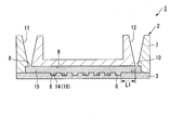
- FIG. 1 is a schematic cross-sectional view of an analysis device in the analysis kit according to the present embodiment.
- FIG. 2 is a schematic diagram illustrating a state in which a mixed solution of a sample and a reagent is injected into the analysis device.
- FIG. 3 is a schematic diagram illustrating a state in which the sealing liquid is injected into the analysis device.
- the analysis kit 1 includes an analysis device 2, beads 14, a reagent 15, and a sealing liquid 17.
- the analysis kit 1 which concerns on this embodiment, it is not essential that the bead 14 is included.
- the analysis kit 1 according to the present embodiment may detect the substance to be measured through the beads 14.
- the analysis kit 1 does not include the beads 14, the analysis kit 1 is introduced into the analysis kit 1 without using the beads 14.
- the substance to be measured may be directly analyzed.
- the object to be analyzed by the analysis kit 1 according to the present embodiment is a sample such as a nucleic acid.
- the analysis kit 1 according to the present embodiment can be used for quantifying nucleic acids.
- the analysis device 2 includes a base portion 3 and a cover portion 7.
- the base portion 3 includes a substrate 4 and a micropore array layer 5 formed on the substrate 4.
- the substrate 4 has, for example, a plate shape with a substantially uniform thickness.
- the substrate 4 is made of a substantially transparent material.
- resin or glass can be applied.
- the substrate 4 may be made of polystyrene or polypropylene.
- substrate 4 should just have the rigidity of the grade which is not damaged at the time of handling by the apparatus which conveys the analysis device 2, or an operator's manual work.
- the micropore array layer 5 is a layer formed by arranging a plurality of through holes.
- the layer thickness of the microhole array layer 5 is, for example, 3 ⁇ m.
- An interval of, for example, 100 ⁇ m is provided between the microhole array layer 5 and the cover portion 7 facing the microhole array layer 5.
- the material of the microhole array layer 5 may be resin, glass, or the like. As a material for the micropore array layer 5, a hydrophobic resin that is compatible with the sealing liquid (having high affinity with the sealing liquid) may be used.
- the material of the microhole array layer 5 may be the same as the material of the substrate 4 or may be different from the material of the substrate 4.
- the microhole array layer 5 may be integrated with the same material as the substrate 4. Further, the microhole array layer 5 may be integrally formed of the same material as the substrate 4.
- Examples of the material of the micropore array layer 5 formed from a resin include cycloolefin polymer, cycloolefin copolymer, silicon, polypropylene, polycarbonate, polystyrene, polyethylene, polyvinyl acetate, fluororesin, and amorphous fluororesin. . These materials shown as examples of the microhole array layer 5 are merely examples, and the material of the microhole array layer 5 is not limited thereto.
- the hydrophobicity in the present embodiment means that the contact angle between the hydrophobic material in the contact angle test and the fluorinated oil (product name FC-40, the standard solution for hydrophobicity evaluation according to the present embodiment) is 25 ° or less. Defined as being in range.
- the contact angle with the fluorinated oil is 10 ° or less.
- the contact angle with the fluorinated oil of cycloolefin polymer (COP), which is a hydrophobic resin is 10 It is about °.
- COP cycloolefin polymer
- the microhole array layer 5 may be directly formed on the substrate 4, or a member on which the microhole array layer 5 is formed is bonded or welded. It may be fixed to the substrate 4 by means.
- the microhole array layer 5 is formed by laminating a member as a material of the microhole array layer 5 on the substrate 4 and patterning a part of this member until the substrate 4 is exposed.
- the micropore array layer 5 is formed by patterning the solid pattern of the hydrophobic film laminated on the substrate 4 by processing such as etching, embossing, or cutting. Is done.
- the portion where the microhole array layer 5 is removed and the substrate 4 is exposed becomes the bottom surface 6a, and the plurality of accommodating portions 6 whose side surfaces are the microhole array layer 5 surrounding the portion where the substrate 4 is exposed are microhole arrays. Formed in layer 5.
- the accommodating portion 6 has a major axis of 7 ⁇ m and a minor axis of 3.5 ⁇ m, for example.
- the depth of the accommodating part 6 is 3 ⁇ m, for example.
- the accommodating part 6 is formed in the hollow column shape whose cross section is an ellipse.
- the opening shape of the accommodating part 6 is not specifically limited.
- the distance (pitch) between the center lines of the plurality of accommodating portions 6 only needs to be larger than the major axis of each accommodating portion 6.
- the center line of the housing portion 6 here refers to a line that passes through the center of the opening of the housing portion 6 and is parallel to the depth direction of the housing portion 6.
- the size of the interval (gap) between the storage units 6 is set according to the resolution with which each storage unit 6 can detect signals independently.
- Each accommodating portion 6 is arranged so as to have a triangular lattice shape with respect to the microhole array layer 5.
- sequence method of each accommodating part 6 is not specifically limited.
- the through-hole formed in the microhole array layer 5 and the surface of the substrate 4 form a bottomed cylindrical minute accommodating portion 6 having the substrate 4 as the bottom surface 6a.
- the volume of the accommodating part 6 may be set as appropriate. When the volume of the container 6 is small, the reaction time until signal detection becomes possible is short.
- the volume of the accommodating part 6 can be 100 picoliters or 100 picoliters or less as an example. More specifically, the volume of the container 6 is such that when the purpose is to reduce the time required to saturate the signal and generate a sufficient signal, the molecule to be analyzed is one in one container 6. It is set based on the amount of liquid that is less than one.
- micropore array layer 5 may be colored.
- the micropore array layer 5 when the micropore array layer 5 is colored, when measuring light such as fluorescence, light emission, absorbance, etc. in the housing 6, light from the other housing 6 adjacent to the housing 6 to be measured. The influence of is reduced.
- the accommodating part 6 formed by the micropore array layer 5 may have a hydrophobic part at the upper part of the accommodating part 6, and may have a colored part at a position closer to the bottom surface 6a of the accommodating part 6 than the hydrophobic part. .
- autofluorescence and noise when measuring fluorescence from the substrate 4 side are reduced, and acquisition of a fluorescence signal is facilitated.
- the transmission of the storage section 6 compared to the case where the position close to the bottom surface 6a of the storage section 6 is transparent. Since the light spot and the light transmission property change, it is easy to focus on the accommodating portion 6 of the micropore array layer 5.
- the colored portion of the storage unit 6 may be formed of, for example, metal vapor deposition or photoresist.
- the micropore array layer 5 When the micropore array layer 5 is integrally formed with the substrate 4, the micropore array layer 5 corresponds to the accommodating portion 6 by performing processing such as etching, embossing, or cutting on the substrate 4. To be formed.
- the micropore array layer 5 may have a hydrophobic part and a hydrophilic part.
- the part which becomes the inner peripheral surface of the accommodating part 6 in the micropore array layer 5 may be formed to be hydrophilic, and the other part in the microhole array layer 5 may be formed to be hydrophobic. .
- the sample 16 and the reagent 15 are unlikely to adhere to the flow path 9.
- the micropore array layer 5 may be subjected to a hydrophilic treatment so that the liquid easily enters the flow path 9 when various liquids are allowed to flow between the micropore array layer 5 and the cover portion 7.
- a hydrophilic treatment method can be appropriately selected from methods such as oxygen plasma treatment and ozone water treatment.
- the micropore array layer 5 is water-repellent when the sealing liquid 17 is fed. It may be made to become.
- the micropore array layer 5 can be made of a material having a water repellent material or a material to which a water repellent is added in advance and then a hydrophilic film is applied.
- the formation of the hydrophilic film can be selected from methods such as lithography and printing.
- a hydrophilic film is applied to the water-repellent micropore array layer 5, when the mixed solution of the sample 16 and the reagent 15 is first fed to the flow path 9, the surface of the micropore array layer 5 is hydrophilic. Therefore, it is easy to hold the liquid in the flow path 9, and when the hydrophilic film or the hydrophilic substance contained in the hydrophilic film is dissolved in the mixed solution of the sample 16 and the reagent 15, the water-repellent microarray layer is exposed. Thus, a state suitable for feeding the oil-based sealing liquid 17 is obtained.
- the surface of the substrate 4 may be hydrophilic and the micropore array layer 5 may be hydrophobic. In this case, the liquid mixture of the sample 16 and the reagent 15 is easily held on the surface of the substrate 4 that forms the bottom surface 6 a of the storage unit 6.
- an aqueous liquid can be easily held in the accommodating portion 6.
- a hydrophobic part and a hydrophilic part can be formed on the surface.
- the cover part 7 is bonded to the base part with a gap between the cover part 7 and the micropore array layer 5.
- the cover part 7 is arrange
- An additive such as a pigment may be added to the cover portion 7 in order to reduce autofluorescence. Since the analysis device 2 according to this embodiment is used to detect fluorescence or phosphorescence, it is preferable that the cover unit 7 does not substantially have autofluorescence.
- the cover part 7 is formed by injection molding or the like, not only the pigment dispersed in the resin in order to reduce autofluorescence, but also various dyes dissolved in the resin can be used as the colored component.
- the dye can be exemplified by various dye methods. Specific examples include direct dyes, basic dyes, cationic dyes, acid dyes, mordant dyes, acid mordant dyes, sulfur dyes, vat dyes, naphthol dyes, disperse dyes, and reactive dyes. In particular, when dyeing a resin, a disperse dye may be selected.
- the cover part 7 and the base part 3 are connected via a spacer 13. Thereby, a space created between the cover part 7, the base part 3, and the spacer 13 becomes the flow path 9.
- the material of the spacer 13 is not particularly limited.
- the spacer 13 has a certain thickness by, for example, laminating a double-sided pressure-sensitive adhesive tape in which an acrylic pressure-sensitive adhesive is laminated on both surfaces of a core material film formed of silicone rubber or an acrylic foam, or an adhesive. Can be appropriately selected and used as the spacer 13.
- the material of the spacer 13 may be resin, metal, paper, inorganic material such as glass, or the like.
- a member that does not easily react with the liquid to be fed can be selected as appropriate.
- a hydrophilic material may be used for a part of the spacer 13 or a hydrophilic process may be performed in order to facilitate introduction of the liquid to be fed into the flow path 9.
- the cover 7 and the microhole array layer 5 are hydrophobic, and only the double-sided adhesive tape of the spacer 13 can be made hydrophilic.
- the cover part 7 has a through-hole part that constitutes an inlet 8 to the flow path 9 and an outlet 10 from the flow path 9.
- the cover unit 7 includes a liquid injection unit 11 that communicates with the inlet 8 and a waste liquid storage unit 12 that communicates with the outlet 10.
- the liquid injection unit 11 communicates with the inlet 8 of the flow path 9 in order to send the mixed liquid of the sample 16 and the reagent 15, the sealing liquid 17, and the like from the inlet 8 of the flow path 9 into the flow path 9. It has a container shape.
- the inner surface of the liquid injection part 11 has a tapered shape so that the diameter gradually increases as the distance from the inlet 8 of the flow path 9 increases.
- the inner surface shape of the liquid injection part 11 is based on the tip shape of a pipette tip, a nozzle, or the like that dispenses a liquid such as a mixed solution of the sample 16 and the reagent 15 or a sealing liquid 17, and the like.
- pouring part 11 may be able to be connected now to the syringe for sending the liquid mixture of the sample 16 and the reagent 15, the sealing liquid 17 grade
- the waste liquid storage unit 12 is connected to the outlet 10 of the flow path 9.
- the volume of the waste liquid storage unit 12 is larger than the volume of the flow path 9. For this reason, even if the sealing liquid 17 is injected into the analysis device 2 so as to push out all of the sample 16 and the reagent 15 from the flow path 9, the sample 16 and the reagent 15 do not overflow from the waste liquid storage unit 12.
- the shortest distance L1 between the waste liquid storage unit 12 and the storage unit 6 is 2 mm or more along the flow path 9. In the present embodiment, the shortest distance between the accommodating portion 6 located closest to the outlet 10 of the channel 9 (the boundary between the channel 9 and the waste liquid storage unit 12) and the outlet 10 of the channel 9 in the plurality of accommodating portions 6.
- the distance (straight line distance) is configured to be 2 mm or more. When the flow path 9 is bent, the shortest distance between the waste liquid storage unit 12 and the storage unit 6 may be a distance measured by bending according to the bent state of the flow path 9.
- the volume of the waste liquid storage unit 12 is configured to be a volume capable of storing a surplus portion of the mixed solution of the sample 16 and the reagent 15 that has not entered the storage unit 6 and a part of the sealing liquid 17.
- the volume of the waste liquid storage unit 12 is, for example, 100 to 1000 ⁇ L, preferably 150 to 500 ⁇ L, and more preferably 200 to 300 ⁇ L.
- the waste liquid storage unit 12 may have two types, for example, a structure for waste liquid with a small amount of waste liquid such as the detection reagent 15 and a structure for waste liquid with a large amount of waste liquid such as the sealing liquid 17.
- the two types of waste liquid structures may have a double structure.
- the structure for waste liquid with a small amount of waste liquid may have a shape capable of storing a small amount of waste liquid by, for example, making the structure of the outlet 10 of the flow path 9 V-shaped.
- the waste liquid storage unit 12 may be provided with a lid so that the waste liquid does not leak out.
- the structure serving as the lid may be made of, for example, plastic or metal.
- cover may be seals, such as a film.
- cover is comprised from thermosetting resins, such as sponges, such as a polyurethane and polyvinyl alcohol, an amino resin, and a melamine resin, and can cover the waste liquid storage part 12 by heating later. It may be like this.
- An absorbent may be disposed in the waste liquid storage unit 12 so that the waste liquid can be absorbed.
- the waste liquid storage section 12 is positioned in the vertical direction of the flow path (positioned above the flow path 9), but the waste liquid storage section 12 is positioned in the horizontal direction of the flow path. May be located. That is, the waste liquid storage unit 12 may be provided on the side surface of the analysis device 2 in FIGS.
- the waste liquid storage unit 12 When the waste liquid storage unit 12 is arranged in the horizontal direction of the flow path, the sample that is not stored in the microhole array can be moved in the observation plane direction (horizontal direction).
- the analysis device 2 can be flattened (thickness can be reduced), so it is easy to carry and also interferes with the apparatus. Can be reduced.
- the arrangement of the waste liquid storage unit is not limited to the vertical direction of the flow channel and the horizontal direction of the flow channel, and is disposed obliquely above the flow channel, diagonally below the flow channel, etc., as long as it does not interfere with sample analysis and detection. However, it is not limited to the illustration of this embodiment.
- the base portion 3 and the cover portion 7 are joined in this manner, so that a plurality of storage portions 6, a flow path 9, a liquid injection portion 11, and a waste liquid storage portion. 12 and.
- the beads 14 can bind to the analysis target and have a specific gravity greater than that of the solvent in the mixed solution of the sample 16 and the reagent 15.
- a bead 14 that can be efficiently dropped into the accommodating portion 6 by gravity may be selected.
- the beads 14 containing a metal may be used as beads 14 for capturing an analysis target.
- the beads 14 include, for example, beads 14 containing at least one metal from metals such as ferrite, iron, copper, gold, silver, platinum, nickel, cobalt, tin, zinc, magnesium, calcium, and aluminum. May be.
- the beads 14 containing ferrite or magnets may be used to guide the beads 14 to the housing portion 6 with a magnet. By using magnetic beads, the beads 14 can be drawn into the housing portion 6 by magnetic force.
- the beads 14 made of resin may be selected as the beads for capturing the analysis target and trapped in the accommodating portion 6 using centrifugal force.
- any material may be selected from resins such as polystyrene, polyethylene, polyester, and polyterephthalate.
- the surface of the bead 14 may be labeled with a DNA probe.
- an antibody label may be applied to the beads 14.
- the shape of the beads 14 may be any size as long as the beads 14 can be accommodated in the accommodating portion 6, and from the opening side of the accommodating portion 6 when one bead 14 is accommodated in one accommodating portion 6. As seen, it is preferable that the shape of the opening of the accommodating portion 6 and the shape of the beads 14 are dissimilar. Since the substance itself that is the analysis target is dispersed in the solvent, it is difficult for the analysis target to enter the accommodating portion 6 if the analysis target remains dispersed in the solvent. In the present embodiment, the analysis target can be captured by the beads 14 having a specific gravity higher than that of the solvent, and the analysis target can be stored in the storage unit 6 together with the beads 14.
- the beads 14 can be of any size as long as the size of the beads 14 can be fixed to the accommodating portion 6, but is preferably 0.1 ⁇ m to 20 ⁇ m. The reason is that it is expected that it is difficult to optically detect the beads 14 when the size of the beads 14 is smaller than 0.1 ⁇ m. Further, if the bead 14 is larger than 20 ⁇ m, the surface area of the bead 14 becomes small, and there is a concern that the hybridization efficiency may be lowered due to a decrease in the number of contact between the probe for capturing the nucleic acid on the bead 14 and the nucleic acid. That is, when the size of the beads 14 is in the range of 0.1 ⁇ m to 20 ⁇ m, optical observation is easy and sufficiently high hybridization efficiency can be obtained.
- the size of the beads 14 may be a size other than the above preferred range (0.1 to 20 ⁇ m) corresponding to the shape of the accommodating portion 6.
- the reagent 15 (see FIG. 2) is sent from the liquid injection unit 11 of the analysis device 2 to the storage unit 6 through the flow path 9.
- the reagent 15 contains an enzyme and a buffer solution.
- the enzyme contained in the reagent 15 corresponds to the content of the biochemical reaction in order to perform a biochemical reaction such as an enzymatic reaction with respect to a template nucleic acid related to the analysis target.
- a biochemical reaction such as an enzymatic reaction with respect to a template nucleic acid related to the analysis target.
- the biochemical reaction with respect to the template nucleic acid is, for example, a reaction in which signal amplification occurs under conditions where the template nucleic acid is present.
- the reagent 15 is selected according to a method capable of detecting a nucleic acid, for example.
- the reagent 15 used in the Invader (registered trademark) method, the LAMP method (registered trademark), the TaqMan (registered trademark) method, the fluorescent probe method, and other methods is the reagent 15 according to this embodiment. included.
- the reagent 15 when a specific gene is to be analyzed (detected), the template nucleic acid itself or a part of the template nucleic acid is to be analyzed.
- the buffer solution is a liquid in which various additives are dissolved in a solvent so as to promote the enzyme reaction in a state where the sample 16 and the reagent 15 are mixed.
- the composition of the buffer may be appropriately selected from known compositions depending on the type of biochemical reaction.
- the reagent 15 may contain an additive such as a surfactant.
- a surfactant By adding a surfactant to the aqueous reagent 15, the beads 14 are dispersed again, so that it becomes easy to accommodate one bead 14 in the one accommodating portion 6. At this time, the beads 14 may be prevented from aggregating by stirring the mixed solution using a pipette.
- the reagent 15 may contain an additive for preventing deterioration of fluorescence to be detected.
- an additive for preventing deterioration of fluorescence to be detected.
- fluorescence may deteriorate due to the influence of active oxygen or the like
- a scavenger reagent, glucose oxidase, or the like may be added to the reagent 15 in order to prevent this.
- the reagent 15 necessary for the reaction may be filled in a bottle, but if the reagent 15 is used a plurality of times from the same bottle, erroneous analysis due to contamination may occur. In order to solve this problem, it is also possible to fill a bottle with an amount of reagent 15 that can be used once and use a bottle that can be used once.
- the shape of the bottle may be a shape in which the cap 15 is opened and the reagent 15 is used, a shape in which the seal 15 is removed and the reagent 15 is taken out, or a shape in which the reagent 15 is sucked by inserting a chip or the like into the lid.
- the reagent 15 may be filled in the container 6 from the beginning instead of filling the reagent 15 in a bottle or the like.
- the reagent 15 may be dried and solidified, or a lid may be provided so that the reagent 15 is filled in a liquid state and does not evaporate.
- the filling amount of the reagent 15 is not particularly limited, but the concentration can be adjusted according to the amount of the sample 16 to be mixed. For example, when an equal amount of the sample 16 is mixed with the reagent 15, the concentration of the reagent 15 can be made twice the final concentration.
- the sealing liquid 17 (see FIG. 3) is a liquid that is supplied to the flow path 9 in order to individually seal the plurality of storage units 6.
- the sealing liquid 17 is a liquid having a composition that does not mix with the sample 16 and the reagent 15.
- the sealing liquid 17 is preferably oily.
- the sealing liquid 17 is a solution that can be sent to the flow path 9 from the liquid injection section 11.
- the oil-based sealing liquid 17 for example, mineral oil, silicone oil, chloroform, squalene, hexadecane, fluorinated liquid FC-40, or the like can be used.
- the specific gravity of the sealing liquid 17 is higher than the specific gravity of the reagent 15 excluding the beads 14.
- Sealing liquid 17 may not be an oily liquid.
- the sealing liquid 17 that is not an oily liquid include a thermosetting resin and a photocurable resin.
- the viscosity of the sealing liquid 17 is, for example, 0.5 to 500 CS, preferably 0.7 to 200 CS, and more preferably 0.8 to 100 CS.
- Sealing liquid 17 may contain an additive in order to reduce autofluorescence. Since the method to be described later uses fluorescence or phosphorescence, the sealing liquid 17 preferably has substantially no autofluorescence.
- “substantially does not have autofluorescence” means that the sealing liquid 17 has no or no autofluorescence of the wavelength used for detection of the experimental result, but influences detection of the experimental result. It means that it is weak enough not to give. For example, if the autofluorescence is about 1/2 or less and 1/10 or less compared to the fluorescence of the detection target, it can be said that it is so weak that it does not affect the detection of the experimental result.
- Examples of the additive added to the sealing liquid 17 include organic or inorganic pigments.
- black pigments are carbon black, acetylene black, iron black, yellow pigments are chrome yellow, zinc yellow, ocher, hansa yellow, permanent yellow, benzine yellow, orange pigments are orange lake, molybdenum Orange, benzine orange, red pigments are red, cadmium red, antimony vermilion, permanent red, risor red, lake red, brilliant scarlet, thioindigo red, blue pigments are cluster, cobalt blue, phthalocyanine blue, ferrocyan blue
- Examples of indigo and green pigments include chrome green, viridian naphthol green, and phthalocyanine green.
- the pigment dispersed in the sealing liquid 17 can be used as the colored component.
- the dye can be exemplified by various dye methods. Specific examples include direct dyes, basic dyes, cationic dyes, acid dyes, mordant dyes, acid mordant dyes, sulfur dyes, vat dyes, naphthol dyes, disperse dyes, and reactive dyes. In particular, when dyeing a resin, a disperse dye is often selected.
- a surfactant may be added to the sealing liquid 17.
- a surfactant By adding a surfactant to the sealing liquid 17, the sealing efficiency can be increased.
- the type and concentration of the surfactant are not particularly limited, but can be set in view of compatibility with the reagent 15 and the material of the micropore array layer 5 and is preferably in the range of 0.001% to 10%.
- the sealing liquid 17 the oil-based sealing liquid 17 and the sealing liquid 17 composed of the thermosetting resin or the photocurable resin can be used in combination.
- a sealing liquid composed of a thermosetting resin after feeding an oil-based sealing liquid, noise when observing fluorescence can be reduced.
- the analysis method according to the present embodiment will be described by taking as an example the case where the analysis device 2 is used. Note that it is not essential to use the analysis device 2 described above for the analysis method.
- the analysis target is a nucleic acid and the concentration of the nucleic acid is measured will be described.
- the beads 14 and the sample 16 including the analysis target are mixed.
- the nucleic acid that is the analysis target is captured on the beads 14 by hybridization.
- the nucleic acid contained in the sample 16 includes nucleic acids other than the nucleic acid to be analyzed. Since the beads 14 are modified with a probe complementary to the nucleic acid to be analyzed, the nucleic acid to be analyzed can be specifically captured.
- the nucleic acid capturing probe bound on the beads 14 for example, an arbitrary one can be selected from nucleic acids such as DNA, RNA, BNA and PNA that form a complementary strand with the target nucleic acid.
- the target nucleic acid is double-stranded.
- the method can be selected from a method using alkali denaturation, a method using heat denaturation, or a method using enzymes.
- a thermal cycler may be used as a method by thermal denaturation. The reason for using the thermal cycler is to efficiently capture the nucleic acid of the target sequence on the beads 14.
- a tube having a structure in which thermal convection is likely to occur may be used in order to further increase the hybridization efficiency.
- a structure in which thermal convection is likely to occur for example, the lower part of the tube is formed thin, the upper part is formed thicker, and the thermal distribution of the solution in the tube may be changed to facilitate thermal convection.
- the heat distribution of the solution may be changed to cause thermal convection.
- the lower portion of the tube may be made of a material that easily transmits heat
- the upper portion may be made of a material that hardly transfers heat.
- buttons may be attached to one device, and each button may be adjusted to a temperature necessary for the reaction.
- a thermal cycler or a hot plate with a plurality of buttons a plurality of hot plates may be prepared and set to necessary temperatures, respectively, and hybridization may be performed. Hybridization may be performed while changing the temperature with a single hot plate.
- the hybridization efficiency may be increased by stirring instead of the heating operation.
- the stirring speed can be selected from 600 rpm to 3000 rpm, but preferably 600 rpm to 2000 rpm in order to prevent nucleic acid damage.
- the stirring time may be any time, but may be stirred overnight if the hybridization efficiency is poor.
- the hybridization solution is put in a container with a magnet and reacted while rotating using a hot plate stirrer or a normal stirrer.
- the hybridization reaction can be carried out while mixing the hybridization solution.
- a condition for increasing the Reynolds number that is, a condition for generating turbulent flow is selected so that the beads 14 are easily redispersed and the agitation is facilitated.
- the Reynolds number is preferably about several hundred to 1,000.
- the bead 14 After the bead 14 captures the object to be analyzed, the bead 14 is recovered and mixed with the reagent 15. For example, when magnetic beads are used, after hybridization, the beads 14 are collected at the bottom of the tube using a magnetic stand, and the supernatant is removed by a pipette. As another method, after the solution containing the hybridized beads is sucked into the pipette tip, the magnet is applied to the pipette tip, and only the liquid is discharged in a state where the beads 14 are captured. Thereafter, the detection reagent 15 may be aspirated, the magnet may be removed, the beads 14 and the reagent 15 may be stirred, and then the reagent 15 containing the beads 14 may be introduced into the detection device.
- the detection reagent 15 may be aspirated, the magnet may be removed, the beads 14 and the reagent 15 may be stirred, and then the reagent 15 containing the beads 14 may be introduced into the detection device.
- the magnet used may be applied from the side of the pipette tip. It is also possible to use a donut-shaped magnet that can be attached to a pipette tip.
- the beads 14 are collected by centrifugation and mixed with the detection reagent 15. In this case, the beads 14 may be separated using a filter having a pore diameter smaller than the diameter of the beads 14.
- the beads 14 may be washed using a washing solution.
- this mixed solution is manually applied to the liquid injection unit 11 of the analysis device 2 as shown in FIG. inject.
- the solution containing the analysis object is introduced from the liquid injection part 11 of the empty analysis device 2, a small amount of solution that fills only a part of the flow path 9 is introduced, and then the sealing liquid 17 is introduced.
- the method of accommodating the mixed solution of the sample 16 and the reagent 15 in the accommodating unit 6 is not limited to the above method.
- the inside of the analysis device 2 is filled with a pre-buffer in advance, and a mixed solution of the sample 16 (bead 14 capturing the analysis target) and the reagent 15 is introduced from the liquid injection unit 11 to replace the pre-buffer.
- the mixed solution may be introduced into the storage unit 6.
- the solution may be introduced from the liquid injection unit 11 of the empty analysis device 2 and the mixed solution may be introduced into the storage unit 6 by applying a centrifugal force to the analysis device 2.
- the liquid mixture may be introduced into the storage unit 6 by continuously introducing a solution or a pre-buffer in which the air in the analysis device 2 can be dissolved from the liquid injection unit 11.
- the inlet 8 and the outlet 10 of the flow path 9 are sealed.
- a method for sealing a type in which a plug is plugged with a lid or a type in which the upper surface of the cover part 7 is sealed with a film seal may be used.
- the beads 14 may be first introduced into the storage unit 6 of the analysis device 2, and then the reagent 15 may be fed to the analysis device 2. In this case, the bead 14 and the reagent 15 come into contact with each other in the storage unit 6 and a biochemical reaction can be started.
- the operation of injecting the mixed liquid from the liquid injection unit 11 to the flow path 9 may be performed by a pipette or a dispensing device.
- the pipette tip from which the solution has been measured is inserted into the inlet 8, and the solution is naturally injected by removing the pipette tip from the pipetter, so that the liquid feeding speed is kept constant with no manual difference.
- it is desirable that the liquid level of the solution in the pipette tip is above the flow path 9 of the analysis device 2.
- the quantity of a solution is more than the quantity which can satisfy
- the sealing liquid 17 is introduced into the flow channel 9.
- the accommodating part 6 is sealed separately.
- the beads 14 accommodated in the accommodating part 6 remain in the accommodating part 6 by gravity, and the reagent 15 accommodated in the accommodating part 6 remains in the accommodating part 6 because the inside of the accommodating part 6 is hydrophilic.
- the sealing liquid 17 By introducing the sealing liquid 17 into the flow path 9 until the sealing liquid 17 enters the waste liquid storage section 12, excess reagent 15 and the sample 16 in the flow path 9 are pushed into the waste liquid storage section 12.
- the specific gravity of the sealing liquid 17 is higher than that of the reagent 15 except for the beads 14, so that the mixed liquid of the reagent 15 and the sample 16 is overlaid on the sealing liquid 17. .
- a treatment for causing a biochemical reaction such as a signal amplification reaction is performed.
- a biochemical reaction such as a signal amplification reaction
- the fluorescence signal can be detected.
- phosphorescence may be detected instead of fluorescence.
- the invader reaction is an isothermal reaction in which a reaction is performed for a predetermined time under a predetermined temperature condition. For this reason, when performing an invader reaction, the analysis device 2 is left still in the chamber where temperature was kept constant. Further, the analysis device 2 may be placed on a hot plate whose temperature is kept constant. As a heating device such as a hot plate for heating to the reaction temperature, a device with a timer may be used.
- the reaction time of the detection reagent 15 may be lengthened, or the fluorescent substance concentration in the detection reagent 15 may be increased. Or you may raise the sensitivity of a detection apparatus.
- the beads 14 used may be fluorescent beads that emit fluorescence having a wavelength different from the wavelength of the fluorescence generated by the reaction between the analysis target and the detection reagent 15. In this case, the beads 14 can be counted by fluorescence detection.
- Detection of fluorescence or phosphorescence can be performed using an apparatus such as a fluorescence microscope.
- the fluorescence microscope used in the present embodiment is connected to a camera for capturing a microscope image and a computer system in which software for analyzing the microscope image captured by the camera is installed.
- a microscope image including a plurality of storage units 6 in the field of view is taken, and the number of storage units 6 in which a signal amplification reaction has occurred is measured based on the presence or absence of fluorescence in the image.
- the number of the accommodating parts 6 in which the beads 14 that have captured the analysis object are included in the entire accommodating part 6 can be measured.
- the fluorescence observation method using the analysis device 2 may be a method in which the analysis device 2 is directly placed on a microscope, but in the case of a small analysis device 2, the analysis device 2 is prevented from falling from the stage of the fluorescence microscope.
- a jig with a refilling rod may be used.
- the jig may be a tape.
- the fluorescent microscope may have a recognition function. For example, in order to focus on the beads 14 in the storage unit 6, the focus can be once adjusted on the storage unit 6, and a certain amount can be finely moved up and down from the location to use the function to search for the beads 14. Further, an image processing / image recognition algorithm may be inserted so that the beads 14 are in focus.
- the registered image particularly how the beads 14 with out-of-focus, illumination unevenness, dirt, etc. are observed is made into an image database because the matching accuracy is improved.
- the position of the bead 14 and the accommodating portion 6 on the Z-axis in the focus direction is memorized in a state in which the edge is made to stand out with transmitted illumination, with a phase difference, and switched to fluorescent illumination to display the bead in a fluorescent image. It is desirable to increase the accuracy if a mechanism for confirming 14 and the accommodating portion 6 is used. It is also possible to lengthen the accommodating portion 6 to widen the focusable range and search for the beads 14.
- the analysis device 2 to be measured is set on the fluorescent microscope. It is also possible to reduce the restriction in the fluorescence microscope by lengthening the accommodating portion 6 vertically and widening the range that can be focused. If there is a difference in the thickness of the fluorescent filter of the fluorescent cube, consider combining the filters so that the optical path length does not change for each fluorescent filter, or even if the objective lens is finely moved to focus on each fluorescent cube Good. Or you may adjust with the optical element in which the optical path length which changes with a filter changes.
- the accommodating portion 6 may be lengthened vertically to increase the focus range (depth of field).
- a mercury lamp, a light emitting diode, or the like may be employed as a light source used in the fluorescence microscope.
- LED light sources have been sold for fluorescent microscopes. Still, there are not so many types of wavelengths, and not all LEDs are stronger excitation light sources than mercury lamps, but if the wavelengths match, strong excitation light that matches the excitation wavelength is possible, and the fluorescence intensity is also strong, It is possible to use a light source with little fluorescence deterioration, and it is possible to shorten the exposure time. If an appropriate filter that can cut the UV side and has a wide excitation light width is selected, the exposure time can be reduced because the excitation light becomes stronger.
- Image processing such as integration photography is performed so that even an objective lens having a magnification of 5 times can be counted. For example, when shooting with a camera having about 4 million pixels, the resolution is increased by changing to the 10 million pixel class. It is also possible to determine the photographing conditions from the photographing result of the low magnification objective lens. For example, if the image is taken with a low-magnification objective lens and the brightness of the entire image is high, the target density is high, so it is possible to reduce the number of shots without observing a large number of storage units 6, and low magnification If the overall brightness is low when shooting with the objective lens, the number of shots can be increased because the target density is low. It is also possible to switch the shooting to a high magnification after shooting at a low magnification.
- the beads 14 and fluorescence may be photographed separately. You may image
- the bead 14 may measure only one field (or several fields) to determine the overall encapsulation rate. In this case, the measurement time can be shortened.
- the bead 14 may have a constant encapsulation rate regardless of the number of experiments, and may be calculated with a default encapsulation rate without performing measurement. In this case, the measurement time can be further shortened.
- the camera that captures the microscope image can be appropriately selected from known cameras including a CCD or a CMOS image sensor. If the magnification of the microscope is 10 times, the field of view becomes narrow, but if the camera has a large CMOS sensor chip, the field of view range becomes large. Since the magnification is reduced, the field of view is widened.
- the amount of data can be reduced by lowering the number of gradations during imaging. Further, the data amount may be reduced by increasing the number of gradations only in necessary portions or excluding unnecessary portions from the imaging range.
- the performance of the camera itself is about 12 bits of gradation, it is possible to prevent digits from being lost by calculating with 14 bits. Note that the number of gradations can be set to 8 bits if only the final result is obtained. In addition, it is desirable to have a redundant server of RAID 1 to 5 and store data in this server.
- whether or not the container 6 emits fluorescence may be a predetermined value as a threshold value.
- the transmittance of the excitation light and the lens on the camera side is weak in the periphery, it may be corrected in advance.
- a solid object such as barium carbonate, which is a solid object, is often used as a reflective object, so it is possible to shoot the standard reflector and correct the amount of light loss using software. is there.
- a method of connecting and correcting the center of the image, that is, the image at the center of the lens, and calculating the ratio of light reduction in the peripheral portion can be used as one of the correction methods.
- Measures such as not using an image with foreign matter or omissions are also necessary, and points that shine in the same size as the housing 6 can be removed by image processing.
- the size of the accommodating part 6 is 5 ⁇ m
- the shining point of the size less than 5 ⁇ m or larger than 5 ⁇ m is not regarded as the accommodating part 6 and can be excluded from the measurement target.
- the positions of the plurality of storage units 6 in the microscope image are stored in advance as patterns in a computer system attached to the microscope apparatus.
- the colored sealing liquid 17 By using the colored sealing liquid 17, autofluorescence of the analysis device 2 and irregular reflection in the analysis device 2 can be suppressed.
- the analysis device 2 can also be measured after measuring the solid film for calibration (entirely formed film) and measuring the focal length.
- autofluorescence can be suppressed to a low level by performing excitation exposure by masking so that excitation light is not exposed except where necessary.
- the computer system automatically outputs the analysis result of the analysis object, for example, the mutation rate and the concentration when the analysis object is a nucleic acid.
- the result is used as a reference, and what is lacking as a condition is clearly displayed to prevent an erroneous result from being automatically generated.
- the fluorescence in the storage unit 6 in which the biochemical reaction has occurred is n times higher than the fluorescence in the storage unit 6 in which the biochemical reaction has not occurred. Since comparisons such as values cannot be made, it is also possible to adopt a method of using this as an error.
- the ratio of the accommodating part 6 in which the fluorescence intensity is higher than a specified value is 10% or more of the whole, for example, an error can be caused.
- a program may be provided that requests data each time it is difficult to determine whether it is an error by storing error data and constructing a database of error references.
- a mechanism for recognizing the possibility of an error may be provided.
- those that show a value higher than a predetermined multiple of the criterion are not included in the accommodating part 6 in which the biochemical reaction has occurred or in the accommodating part 6 in which the biochemical reaction has occurred (that is, ignored). It is also possible to adopt the method.
- the excitation light can be turned off and the previous image can be displayed, or the excitation light can be gradually increased from a weak point. . Even if the excitation light ends with a strong setting, if the sample is changed, it can start from a weak point. Or, in the case of strong light, the image is taken with the camera in conjunction with the excitation light ON. The sensitivity of the camera starts with exposure of maximum or about 1 second (initial setting can be set to 0.1 second, 5 seconds, or 10 seconds). During that time, the excitation light cannot be strengthened.
- an image without the bead 14 in advance and then take an image with the bead 14 and extract an image of the bead 14 based on the difference between the images. For example, when the focus is slightly shifted, the image is slightly tilted, the center is in alignment, the right is blurred by +, the left is blurred by-, and the lighting is uneven. As an image, an image of the housing 6 without the beads 14 may be registered.
- the bead 14 can be extracted and counted by an image processing algorithm that registers a reference image of the bead 14 and determines a similar one. If many examples are collected as an image database, the relevance rate can be increased. Depending on the wavelength of the fluorescence used when counting the accommodating portions 6 that emit fluorescence, another fluorescence wavelength may be easier to count. Alternatively, beads 14 that can be detected at other wavelengths may be selected and used.
- the analysis device 2 As described above, by using the analysis device 2 according to the present embodiment, it is possible to count the storage units 6 that emit fluorescence during fluorescence observation due to a biochemical reaction occurring in the storage unit 6.
- the mixed liquid and the sealing liquid 17 are agitated in the vicinity of the interface 18 between the mixed liquid of the sample 16 and the reagent 15 and the sealing liquid 17, or the solute in the mixed liquid is transferred to the sealing liquid 17. It may be possible to migrate. Since the mixture of the sample 16 and the reagent 15 undergoes a biochemical reaction that emits fluorescence, the mixture is in a state capable of emitting fluorescence in response to irradiation with excitation light. For this reason, if the surplus of the mixture of the sample 16 and the reagent 15 is located in the vicinity of the storage unit 6, it becomes difficult to distinguish the fluorescence due to the surplus and the fluorescence in the storage unit 6.
- the interface 18 between the mixed liquid and the sealing liquid 17 is the storage unit. It is in a position sufficiently away from 6. For this reason, in this embodiment, the solute due to the above stirring and transfer is less likely to affect the biochemical reaction in the container 6. Moreover, although the solute by the above stirring and transfer can emit fluorescence in response to the irradiation with excitation light, it is sufficiently separated from the housing portion 6 and thus hardly affects the fluorescence measurement.
- the reagent 15 stored in the waste liquid storage unit 12 is unlikely to interfere with the fluorescence observation in the storage unit 6, so that highly reproducible analysis is performed. be able to.
- the analysis kit 1 and the analysis device 2 according to the present embodiment do not require a separate device for collecting the waste liquid, and thus can be downsized as a whole.
- the specific gravity of the sealing liquid 17 is higher than the specific gravity of the reagent 15 excluding the beads 14, so that the surplus in the mixed liquid of the sample 16 and the reagent 15 is stored in the waste liquid storage unit 12. It is difficult to flow backward from the waste liquid storage unit 12 to the flow path 9 after the transition.
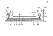
- FIG. 4 is a schematic cross-sectional view of an analysis device in the analysis kit according to the present embodiment.
- the analysis device 2 ⁇ / b> A according to this embodiment the shortest distance between the waste liquid storage unit 12 and the storage unit 6 does not have to be 2 mm or more along the flow path 9.
- the sample 16 and the reagent 15 are sealed with the sample 16 and the reagent 15 when the sample 16 and the reagent 15 are stored in the waste liquid storage unit 12 in a state of being layered on the sealing liquid 17.
- the shortest distance between the interface 18 with the liquid 17 and the container 6 is 2 mm or more along the flow path 9.
- the position of the interface 18 corresponds to the amount of the sealing liquid 17 injected from the liquid injection part 11. That is, in the present embodiment, an amount of the sealing liquid 17 necessary to make the shortest distance L2 between the interface 18 and the accommodating portion 6 be 2 mm or more along the flow path 9 is injected from the liquid injection portion 11. It is like that.
- the shortest distance L2 between the interface 18 and the container 6 in the present embodiment is, for example, the flow path 9 and the waste liquid from the container 6 to the interface 18 that is closest to the waste liquid storage unit 12 in the plurality of containers 6. It may be a distance measured along a straight line bent so as to be connected through the storage unit 12 in the shortest distance.
- the shortest distance between the interface 18 and the accommodating portion 6 may be a distance measured so as to pass through the center of the flow path 9.
- the injection of the sealing liquid 17 may be performed manually.
- the sealing liquid 17 may be injected by a system that automatically injects a predetermined amount of the sealing liquid 17.
- FIG. 4 shows an example in which the waste liquid storage unit 12 is positioned in the vertical direction of the flow path (located above the flow path 9), but the waste liquid storage unit 12 is positioned in the horizontal direction of the flow path. May be. That is, the waste liquid storage unit 12 may be provided on the side surface of the analysis device 2A in FIG.
- the sample that is not stored in the microhole array can be moved in the observation plane direction (horizontal direction). Even when the waste storage part 12 is arranged in the horizontal direction of the flow path, the interface 18 between the sample 16 and the reagent 15 and the sealing liquid 17 when stored in the waste liquid storage part 12 is formed.
- the shortest distance between the interface 18 and the accommodating portion 6 is preferably configured to be separated by 2 mm or more along the flow path 9.
- the analysis device 2A can be flattened (thickness can be reduced), so it is easy to carry and interferes with the apparatus. Can be reduced.
- the arrangement of the waste liquid storage unit 12 is not limited to the vertical direction of the flow path and the horizontal direction of the flow path. It may be arrange
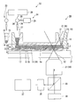
- FIG. 5 is a schematic diagram of an analysis apparatus (analysis system) according to the present embodiment.
- the analysis apparatus (analysis system) 20 according to the present embodiment shown in FIG. 5 is automatically performed using the analysis device 2 disclosed in the first embodiment and the analysis device 2A disclosed in the second embodiment.
- This is a device including a system for performing analysis. Below, the system which analyzes using the analysis device 2 disclosed by 1st Embodiment is demonstrated.
- the analysis device 2A disclosed in the second embodiment can be similarly used in the analysis system 20 of the present embodiment.
- the analysis system 20 includes a stage 21 for placing the analysis device 2, a liquid injection device 22 for injecting various liquids into the analysis device 2 on the stage 21, an optical system 30 including an objective lens 31, and an optical system.
- An imaging unit 35 connected to the system 30, a light source unit 36 that irradiates the accommodating unit 6 in the analysis device 2 through the optical system 30 with excitation light, and an analysis device 37 that analyzes an image captured by the imaging unit 35. Yes.
- the liquid injection device 22 has a first liquid injection part 23 for injecting the sample 16 and the reagent 15 into the analysis device 2 and a second liquid injection part 24 for injecting the sealing liquid 17 into the analysis device 2. is doing.
- the first liquid injection unit 23 a configuration of a known automatic dispensing device can be appropriately selected and employed.
- the first liquid injection unit 23 dispenses this mixed liquid from the container (not shown) accommodated in a state where the sample 16 and the reagent 15 are mixed to the liquid injection unit 11 of the analysis device 2.
- the first injection unit 23 cooperates with the apparatus (not shown) for performing the hybridization process disclosed in the first embodiment.
- the first injection part 23 The captured beads 14 may be mixed with the reagent 15 and injected into the analysis device 2.
- the second liquid injection unit 24 includes, for example, a tank 25, a pipe 26, a nozzle 27, a pump 28, and a control unit 29.
- the tank 25 and the nozzle 27 are connected by a tube, and a pump 28 is connected to the pipe 26.
- the control unit 29 determines the injection amount of the sealing liquid 17 corresponding to the configurations of the analysis device 2 and the optical system 30, drives the pump 28, and seals from the tank 25 to the analysis device 2 via the nozzle 27. Liquid 17 is fed.
- the optical system 30 can set the focal point of the objective lens 31 in the vicinity of the bottom surface 6a of each storage unit 6 of the analysis device 2 on the stage 21 and is used for observing fluorescence in each storage unit 6.
- the focal position 32 can be set on the bottom surface 6 a of each storage unit 6.
- a certain range (focal depth 33) is set around the focal position 32 in the optical axis direction of the objective lens 31. Imaging can be suitably performed.
- the imaging unit 35 has an image sensor for detecting fluorescence transmitted to the imaging unit 35 through the optical system 30.
- the imaging unit 35 captures the fluorescence image and outputs it to the analysis device 37.
- the light source unit 36 irradiates the analysis device 2 through the optical system 30 with excitation light having a wavelength corresponding to the type of fluorescent labeling substance used in the biochemical reaction using the analysis device 2.
- the analysis device 37 determines the presence or absence of fluorescence in the storage unit 6 of the analysis device 2 based on the image captured by the imaging unit 35. Furthermore, the analysis apparatus 37 measures the number of the accommodating units 6 emitting fluorescence among the accommodating units 6 in the analysis device 2, and calculates the concentration of the analysis target in the sample 16 injected into the analysis device 2.
- the control unit 29 stores data relating to the shape of the analysis device 2 and data relating to the focal depth 33 of the objective lens 31.
- the data relating to the shape of the analysis device 2 includes at least the position of the bottom surface 6a of the container 6 in the optical axis direction of the objective lens 31, the amount of liquid injected into the analysis device 2, and the surface position of the liquid in the waste liquid storage unit 12. It is the data which shows the relationship.
- the position of the bottom surface 6a can be based on, for example, the upper surface of the stage 21 (the surface on which the analysis device 2 is placed). Data indicating the relationship between the amount of liquid injected into the analysis device 2 and the surface position of the liquid in the waste liquid storage unit 12 is stored in the control unit 29 as a table, a calculation formula, or the like.
- the control unit 29 uses the information on the position of the bottom surface 6 a of the housing unit 6 and the depth of focus 33 of the objective lens 31 when the focal position 32 of the objective lens 31 is located on the bottom surface 6 a of the housing unit 6.
- the width of the in-focus range in the optical axis direction of the objective lens 31 is acquired. This range is determined in advance based on the lens data of the objective lens 31 so that, for example, the frequency of erroneous determination occurring when the presence or absence of fluorescence is determined using the analysis device 37 is equal to or less than a predetermined threshold. ing.
- the control unit 29 acquires a distance (fluorescence obtainable distance 34) from the bottom surface 6 a of the housing unit 6 to a boundary far from the objective lens 31 in a focused range.
- the control unit 29 determines that the distance L3 from the bottom surface 6a of the storage unit 6 to the surface position is as described above.
- the injection amount of the sealing liquid 17 is determined so that the distance L3 is preferably longer than the above-described fluorescence acquirable distance 34 so that the fluorescence acquirable distance 34 is greater than or equal to 34.
- the position of the interface 18 between the mixed liquid of the sample 16 and the reagent 15 and the sealing liquid 17 in the waste liquid storage unit 12 is accommodated in the optical axis direction of the objective lens 31.
- the distance from the bottom surface 6 a of the portion 6 is greater than the fluorescence obtainable distance 34.
- the analysis system 20 of this embodiment When the analysis system 20 of the present embodiment is used, when the injection of the sealing liquid 17 is completed, the surplus of the sample 16 and the reagent 15 and a part of the sealing liquid 17 supplied to the flow path 9 are stored in the waste liquid. Stored in the section 12 as waste liquid. The mixed solution of the sample 16 and the reagent 15 is overlaid on the sealing liquid 17 in the waste liquid storage unit 12. The position of the interface 18 between the mixed solution of the sample 16 and the reagent 15 and the sealing liquid 17 in the waste liquid storage unit 12 is farther from the bottom surface 6a of the storage unit 6 than the fluorescence obtainable distance 34 in the optical axis direction of the objective lens 31. In the position.
- the sample 16 and the reagent 15 stored in the waste liquid storage unit 12 are located outside the in-focus range in the optical system 30. Since the liquid mixture of the sample 16 and the reagent 15 in the waste liquid storage unit 12 includes the analysis object and the reagent 15, the liquid can be emitted in response to the irradiation of the excitation light. In this embodiment, when excitation light is irradiated to the liquid mixture in the waste liquid storage part 12 through the optical system 30, the liquid intensity in the waste liquid storage part 12 is at a position away from the focal position 32, so that the fluorescence intensity is low. . Furthermore, since the liquid mixture in the waste liquid storage unit 12 is not in focus, even if it emits fluorescence, it does not become a light spot on the image.
- the S / N ratio between the fluorescence in the storage unit 6 near the waste liquid storage unit 12 and the fluorescence in the waste liquid storage unit 12 is calculated in the storage unit 6 in the analysis device 37. It can be sufficiently increased to the extent that the presence or absence of fluorescence can be determined.
- the control unit 29 controls the injection amount of the sealing liquid 17 to increase the S / N ratio between the fluorescence in the storage unit 6 near the waste liquid storage unit 12 and the fluorescence in the waste liquid storage unit 12. be able to.
- the reagent 15 stored in the waste liquid storage unit 12 can perform a highly reproducible analysis that is unlikely to interfere with fluorescence observation in the storage unit 6, and the storage unit 6.
- the analysis device 2 can be downsized by shortening the distance from the waste liquid storage unit 12 to the waste liquid storage unit 12.
- FIG. 5 as in the first and second embodiments, the example in which the waste liquid storage unit 12 is positioned in the vertical direction of the flow channel (located above the flow channel) is shown.
- the waste liquid storage unit 12 may be located in the horizontal direction of the flow path. That is, the waste liquid storage unit 12 may be provided on the side surfaces of the analysis devices 2 and 2A in FIG.
- the sample that is not stored in the microhole array can be moved in the observation plane direction (horizontal direction).
- the interface 18 between the sample 16 and the reagent 15 and the sealing liquid 17 when stored in the waste liquid storage part 12 is formed.
- the shortest distance between the interface 18 and the accommodating portion 6 is preferably 2 mm or more along the flow path 9.
- the analysis devices 2 and 2A can be flattened (thickness can be reduced). Interference with the apparatus used for the operation can be reduced.
- the arrangement of the waste liquid storage unit 12 is not limited to the vertical direction of the flow path and the horizontal direction of the flow path. It may be arrange
- the analysis device 2 of this modification is used for an analysis that does not use the beads 14.
- the analysis object is introduced into the container 6 and the analysis is performed.
- pre-amplification may be performed before introducing the solution containing the analysis object into the analysis device 2.
- Preamplification may use the polymerase chain reaction (PCR). PCR may be performed from several cycles to several tens of cycles as necessary, preferably 10 cycles or more.
- PCR polymerase chain reaction
- reverse transcription PCR may be performed before introducing the solution containing the analysis target into the analysis device 2.
- amplification reactions may be carried out using commercially available tubes, but a site for performing pre-amplification may be provided in the analysis device 2. After the pre-amplification, the solution containing the amplification reagent 15 and the analysis target is sent to the analysis device 2, and after performing an amplification reaction in the analysis device 2, the detection reaction reagent 15 is added, and then the sealing liquid 17 And the detection reaction (signal amplification reaction) may be performed on the housing portion 6.
- the analysis may be performed by increasing the number of the analysis target existing in the storage unit 6 by using a plurality of devices.
- the analysis may be performed using a plurality of devices. Further, in this case, the solution containing the analysis target may be evaporated and then introduced into the device.
- the diameter of the accommodating portion 6 can be selected in the range of 100 nm to 100 ⁇ m, and is preferably 1 ⁇ m to 100 ⁇ m. This is because it is considered that it is difficult to hold the nucleic acid in the housing portion 6 when the diameter of the housing portion 6 is smaller than 1 ⁇ m. Moreover, if the diameter of the accommodating part 6 is larger than 100 ⁇ m, a plurality of nucleic acids will be contained in one accommodating part 6.
- the depth of the accommodating part 6 can be selected in the range of 100 nm or more and 100 ⁇ m or less, it is preferably 1 to 10 ⁇ m. If the depth of the accommodating part 6 is smaller than 1 ⁇ m, it becomes difficult to hold the nucleic acid in the accommodating part 6. Moreover, if the depth of the accommodating part 6 is larger than 100 ⁇ m, a plurality of nucleic acids may be contained in one accommodating part 6. When increasing the volume of the accommodating part 6, there is a concern about a decrease in the reaction rate. Therefore, by using the vertically long accommodating portion 6, even if the reaction rate decreases, the fluorescence signals in the observation direction can be integrated, and observation can be facilitated.
- the ratio of the depth and the diameter of the accommodating portion 6 is preferably 1: 1 or more. However, if the diameter becomes too small, observation with a camera becomes difficult, so it is necessary to determine the length in consideration of the length of the diameter.
- the ratio of the depth and the diameter of the accommodating portion 6 is more preferably 1: 2 or more.
- Example 1 ⁇ Production of analysis device> A base portion 3 having a thickness of 0.6 mm, made of cycloolefin polymer, and having 1 million holes with a diameter of 5 ⁇ m was produced by injection molding.
- a cover glass was placed on the base 3 as the cover 7 so that the gap with the base 3 was 100 ⁇ m.
- a spacer 13 made of an adhesive tape was disposed between the base 3 and the cover 7.
- nucleic acid is contained between the base body part 3 and the cover part 7 via the liquid injection part 11 using the first liquid injection part 23 of the liquid injection apparatus 22 in the analysis apparatus as shown in FIG.
- a non-aqueous liquid was fed as a replacement liquid, and the entire area of the hole having a diameter of 5 ⁇ m and the gap between the base portion 3 and the cover portion 7 was filled with the aqueous liquid.
- the composition of the aqueous liquid is 20 mM MOPS pH 7.5, 15 mM NaCl, 6.25 mM MgCl 2 .
- the artificial synthetic DNA was mixed so that the concentration of the artificial synthetic DNA was 3 pM so that one molecule could enter one of the holes of 5 ⁇ m in diameter formed in the base portion 3.
- a cylindrical micropore having a diameter of 5 ⁇ m and a height of 3 ⁇ m has a volume of 59 fL, and assuming that it follows a Poisson distribution, it is estimated that the artificially synthesized DNA concentration of 3 pM enters 10% of 1 million micropores.
- FC-40 SIGMA
- the distance L3 from the bottom surface 6a of the storage unit 6 to the interface 18 between the sample and reagent mixture and the sealing liquid in the waste liquid storage unit 12 is 0 mm (test A), 1 mm.
- Test A the distance L3 from the bottom surface 6a of the storage unit 6 to the interface 18 between the sample and reagent mixture and the sealing liquid in the waste liquid storage unit 12 is 0 mm (test A), 1 mm.
- Test B The following fluorescence observation measurement was performed under the conditions in which the injection amount of the sealing liquid 17 was changed so as to be 2 mm (Test C), 4 mm (Test D), and 8 mm (Test E).
- the analysis device of this example having 1 million independent nucleic acid detection reaction vessels was incubated for 15 minutes under the condition of 63 °, and the fluorescence microscope (the optical system 30, the objective lens 31, the light source unit 36 in FIG. 5) was incubated. , Corresponding to the imaging unit 35 and the analysis device 37), and the fluorescence intensity of each hole was observed.
- the post-reaction analysis device took a fluorescent image using a fluorescent microscope.
- control part of the fluorescence microscope was comprised so that the position of the some accommodating part in the analysis device mounted on the stage and the focal depth of the objective lens in a fluorescence microscope could be acquired.
- the depth of focus of the objective lens used in the fluorescence microscope according to Example 1 was 3 ⁇ m.
- test A in which the distance L3 is 0 mm, the number of nucleic acid detection reaction containers that emit fluorescence cannot be measured due to the influence of fluorescence emission of the sample present in the flow path.
- test B where the distance L3 is 1 mm, as in the test A, the influence of the background fluorescence emission, which is considered to be derived from the nucleic acid present in the waste liquid storage unit, is large, and the number of nucleic acid detection reaction containers emitting fluorescence is measured. could not.
- the influence of background fluorescence that is considered to be derived from the nucleic acid present in the waste liquid storage unit The number of the nucleic acid detection reaction containers that emit fluorescence could be measured without receiving the light.
- the number of nucleic acid detection reaction vessels that emit fluorescence is reproduced without being affected by background fluorescence that is thought to be derived from nucleic acids present in the waste liquid storage unit. It was possible to measure with good performance and with less influence of noise generation.
- 2 mm corresponds to the fluorescence obtainable distance 34 according to the analysis apparatus using the analysis device according to the present embodiment (strictly, the fluorescence obtainable distance 34 between 1 mm and 2 mm). It is considered that 2 mm corresponds to the threshold value with the fluorescence obtainable distance 34). That is, when the relationship of the fluorescence obtainable distance 34 (2 mm)> L3 is satisfied, it is difficult to measure the number of nucleic acid detection reaction containers that emit fluorescence. On the other hand, when the relationship of the fluorescence obtainable distance 34 (2 mm) ⁇ L3 was satisfied, it was confirmed that the number of nucleic acid detection reaction containers emitting fluorescence can be measured in this example.
- the distance L3 from the bottom surface of the container to the interface between the sample and reagent mixture and the sealing liquid in the waste liquid storage is 2 mm or more (more than the fluorescence acquisition distance). According to this, it was confirmed that the number of nucleic acid detection reaction vessels that emit fluorescence can be measured without being affected by background fluorescence emission that is thought to be derived from nucleic acids present in the waste liquid storage unit.
- the analysis device is used as an array device for nucleic acid quantification
- the analysis target using the analysis device is not limited to the nucleic acid.
- the analysis device according to the embodiment of the present invention can be applied to an array device for analyzing proteins, lipids, and sugar chains.
- the container is opened vertically (for the mixed solution).
- the analysis target in the sample is accommodated together with the beads in the container by containing beads having a specific gravity smaller than that of the solvent in the reagent. be able to.
- various liquids used for biochemical reactions may be sent to the flow path in advance, and the flow path may be filled with the solution.
- the detection reaction reagent can be filled in the analysis device in advance, the sealing liquid can be sent to the flow path after long-term storage, and then the measurement can be performed.
- the inlet and outlet between the micropore array layer and the cover part may be sealed with a lid material.
- the lid material may be a molded product such as plastic or metal, a polymer-like gel material, a film-like sealing material, or adhesion to the cover portion by lamination.
- the analysis device disclosed in each of the above embodiments may be provided in a state where a plurality of analysis devices are connected to each other.
- the analysis device may be used separately for each analysis.
- the analysis device may have a space for performing a hybridization reaction.
- a hybridization reaction can be performed in the waste liquid storage unit.
- the waste liquid storage unit positions the mixed liquid of the sample and the reagent in the waste liquid storage unit outside the range of the focal depth of the objective lens. As long as it is arranged so that it can be, it may be at an arbitrary position in the analysis device. For example, when observing fluorescence with respect to each storage unit, the outlet of the flow path and the waste liquid storage unit may be positioned on the optical axis of the objective lens. Further, the analysis device may have only one through hole so that the inlet and the outlet of the flow path are used in common. In this case, the size of the through hole is not particularly limited.
- a through hole having a diameter that includes a plurality of accommodating portions when viewed from the thickness direction of the substrate may be formed in the cover portion.
- the upper surface of the flow path is opened by the through hole in the region where the container is disposed, and in this region, the mixed liquid of the sample and the reagent in the container is sealed with the sealing liquid.
- the surplus of the liquid mixture of the sample and the reagent is overlaid on the sealing liquid.
- the control unit determines the injection amount of the sealing liquid so that the surplus of the liquid mixture of the sample and the reagent is moved by the sealing liquid outside the range of the focal depth of the objective lens.
- the S / N ratio between the fluorescence from the surplus of the liquid mixture of the reagent and the reagent and the fluorescence from the inside of the container can be increased.
Landscapes
- Health & Medical Sciences (AREA)
- Chemical & Material Sciences (AREA)
- General Health & Medical Sciences (AREA)
- Analytical Chemistry (AREA)
- Pathology (AREA)
- Life Sciences & Earth Sciences (AREA)
- Biochemistry (AREA)
- Physics & Mathematics (AREA)
- General Physics & Mathematics (AREA)
- Immunology (AREA)
- Nuclear Medicine, Radiotherapy & Molecular Imaging (AREA)
- Dispersion Chemistry (AREA)
- Hematology (AREA)
- Clinical Laboratory Science (AREA)
- Chemical Kinetics & Catalysis (AREA)
- Apparatus Associated With Microorganisms And Enzymes (AREA)
- Investigating, Analyzing Materials By Fluorescence Or Luminescence (AREA)
- Automatic Analysis And Handling Materials Therefor (AREA)
- Optical Measuring Cells (AREA)
- Measuring Or Testing Involving Enzymes Or Micro-Organisms (AREA)
Abstract
Un appareil d'analyse de la présente invention comprend : un dispositif d'analyse comprenant de multiples parties de réception qui reçoivent chacune en leur sein un échantillon et un réactif destiné à être utilisé dans une réaction biochimique, comprenant un trajet d'écoulement qui a une entrée et une sortie et qui relie les multiples parties de réception les unes aux autres, comprenant une partie d'injection de liquide qui est reliée à l'entrée de manière à permettre l'alimentation, dans le trajet d'écoulement, de l'échantillon et du réactif et d'un liquide de scellement qui scelle individuellement les multiples parties de réception, et comprenant une partie de stockage de liquide de déchet qui est reliée à la sortie de manière à stocker, en tant que liquides de déchet, en son sein des parties en excès de l'échantillon et du réactif qui sont reçus dans chacune des multiples parties de réception, et une partie du liquide de scellement fourni dans le trajet d'écoulement ; une platine sur lequel le dispositif d'analyse est placé ; un objectif et un système optique qui sont configurés pour appliquer une lumière d'excitation sur les multiples parties de réception du dispositif d'analyse placé sur la platine, et permettre l'observation d'une fluorescence générée dans les multiples parties de réception à cause de la lumière d'excitation ; et une unité de commande qui provoque l'injection d'une quantité prédéterminée du liquide de scellement à partir de la partie d'injection de liquide de telle sorte qu'une interface entre le liquide de scellement et les parties en excès de l'échantillon et du réactif est formée dans la partie de stockage de liquide de déchet, la distance entre la surface inférieure de chacune des multiples parties de réception et l'interface, dans la partie de stockage de liquide de déchet, entre le liquide de scellement et les parties en excès de l'échantillon et du réactif n'étant pas inférieure à une distance pouvant être obtenue par fluorescence.
Priority Applications (3)
| Application Number | Priority Date | Filing Date | Title |
|---|---|---|---|
| JP2018514738A JP6835075B2 (ja) | 2016-04-28 | 2017-04-28 | 解析装置 |
| US16/173,102 US11559804B2 (en) | 2016-04-28 | 2018-10-29 | Analysis devices, analysis kits, and analysis systems |
| US18/067,264 US12370545B2 (en) | 2016-04-28 | 2022-12-16 | Analysis devices, analysis kits, and analysis systems |
Applications Claiming Priority (2)
| Application Number | Priority Date | Filing Date | Title |
|---|---|---|---|
| JP2016-091949 | 2016-04-28 | ||
| JP2016091949 | 2016-04-28 |
Related Child Applications (1)
| Application Number | Title | Priority Date | Filing Date |
|---|---|---|---|
| US16/173,102 Continuation US11559804B2 (en) | 2016-04-28 | 2018-10-29 | Analysis devices, analysis kits, and analysis systems |
Publications (1)
| Publication Number | Publication Date |
|---|---|
| WO2017188441A1 true WO2017188441A1 (fr) | 2017-11-02 |
Family
ID=60160833
Family Applications (1)
| Application Number | Title | Priority Date | Filing Date |
|---|---|---|---|
| PCT/JP2017/016997 Ceased WO2017188441A1 (fr) | 2016-04-28 | 2017-04-28 | Dispositif d'analyse, kit d'analyse, et système d'analyse |
Country Status (3)
| Country | Link |
|---|---|
| US (2) | US11559804B2 (fr) |
| JP (3) | JP6835075B2 (fr) |
| WO (1) | WO2017188441A1 (fr) |
Cited By (7)
| Publication number | Priority date | Publication date | Assignee | Title |
|---|---|---|---|---|
| WO2020183938A1 (fr) * | 2019-03-08 | 2020-09-17 | 株式会社フコク | Puce à microcanal |
| EP3712275A4 (fr) * | 2017-11-17 | 2020-12-02 | Toppan Printing Co., Ltd. | Procédé de détection de molécules cibles |
| WO2020241689A1 (fr) * | 2019-05-30 | 2020-12-03 | 凸版印刷株式会社 | Procédé d'introduction de liquide dans des puits |
| JPWO2022050247A1 (fr) * | 2020-09-02 | 2022-03-10 | ||
| EP3974844A4 (fr) * | 2019-05-21 | 2022-08-03 | Toppan Inc. | Procédé de détection de substance cible |
| JP2023507599A (ja) * | 2019-12-18 | 2023-02-24 | ローベルト ボツシユ ゲゼルシヤフト ミツト ベシユレンクテル ハフツング | 流体を収容するための収容ユニット、収容ユニットを製造するための方法および装置、収容ユニットを操作するための方法および装置、ならびに収容装置 |
| WO2025263386A1 (fr) * | 2024-06-18 | 2025-12-26 | キヤノン株式会社 | Dispositif de mesure de réaction |
Families Citing this family (8)
| Publication number | Priority date | Publication date | Assignee | Title |
|---|---|---|---|---|
| TWI698638B (zh) * | 2017-12-28 | 2020-07-11 | 美商伊路米納有限公司 | 具有降低的螢光範圍雜訊的檢測器以及用於降低螢光範圍雜訊的方法 |
| CN111944679A (zh) * | 2019-05-17 | 2020-11-17 | 湖南乐准智芯生物科技有限公司 | 一种pcr微反应室阵列结构及进行混合液封装的方法 |
| GB2586246B (en) * | 2019-08-13 | 2021-12-15 | Ft Tech Uk Ltd | Self-draining sensor cavity |
| CN110646493A (zh) * | 2019-09-25 | 2020-01-03 | 深圳先进技术研究院 | 一种微流控芯片、蛋白检测方法、装置及系统 |
| JP2022049382A (ja) * | 2020-09-16 | 2022-03-29 | 株式会社エンプラス | 流体取扱装置および流体取扱装置の製造方法 |
| CN113358621B (zh) * | 2021-06-10 | 2022-11-18 | 深圳市核子基因科技有限公司 | 一种同轴光纤荧光基因检测装置及其检测方法 |
| WO2023214516A1 (fr) * | 2022-05-02 | 2023-11-09 | 凸版印刷株式会社 | Kit de détection, liquide d'étanchéité, procédé de conservation de liquide d'étanchéité et procédé de détection d'échantillon |
| WO2025126814A1 (fr) * | 2023-12-12 | 2025-06-19 | 東ソー株式会社 | Procédé de spécification de région de mesure |
Citations (6)
| Publication number | Priority date | Publication date | Assignee | Title |
|---|---|---|---|---|
| JP2005506541A (ja) * | 2001-10-26 | 2005-03-03 | エヌティーユー ベンチャーズ ピーティーイー リミテッド | 試料調製一体型チップ |
| JP2010008223A (ja) * | 2008-06-26 | 2010-01-14 | Aisin Seiki Co Ltd | マイクロチップ |
| JP2010066195A (ja) * | 2008-09-12 | 2010-03-25 | Seiko Epson Corp | 生体試料反応用チップ、生体試料反応用チップに反応液を充填する遠心装置、および生体試料反応用チップに反応液を充填する方法 |
| JP2014070991A (ja) * | 2012-09-28 | 2014-04-21 | Toppan Printing Co Ltd | 複数試料を分析するための試料分析チップとその分析装置 |
| JP2015079001A (ja) * | 2009-07-24 | 2015-04-23 | アコーニ バイオシステムズAkonni Biosystems | フローセルデバイス |
| WO2015115635A1 (fr) * | 2014-01-31 | 2015-08-06 | 凸版印刷株式会社 | Kit d'analyse de biomolécule et procédé d'analyse de biomolécule |
Family Cites Families (5)
| Publication number | Priority date | Publication date | Assignee | Title |
|---|---|---|---|---|
| JP2004003888A (ja) * | 2002-05-31 | 2004-01-08 | Olympus Corp | 生体関連物質の検査装置とその反応ステージ |
| KR20100019409A (ko) * | 2007-01-22 | 2010-02-18 | 웨이퍼젠, 인크. | 고효율 화학 반응을 위한 장치 및 방법 |
| US9180453B2 (en) * | 2008-08-15 | 2015-11-10 | University Of Washington | Method and apparatus for the discretization and manipulation of sample volumes |
| US9952237B2 (en) | 2011-01-28 | 2018-04-24 | Quanterix Corporation | Systems, devices, and methods for ultra-sensitive detection of molecules or particles |
| JP6583602B2 (ja) * | 2014-09-19 | 2019-10-02 | コニカミノルタ株式会社 | 細胞内の核酸の解析方法ならびにそのためのシステムおよびキット |
-
2017
- 2017-04-28 WO PCT/JP2017/016997 patent/WO2017188441A1/fr not_active Ceased
- 2017-04-28 JP JP2018514738A patent/JP6835075B2/ja active Active
-
2018
- 2018-10-29 US US16/173,102 patent/US11559804B2/en active Active
-
2021
- 2021-02-02 JP JP2021015224A patent/JP7036243B2/ja active Active
-
2022
- 2022-03-03 JP JP2022032483A patent/JP7392749B2/ja active Active
- 2022-12-16 US US18/067,264 patent/US12370545B2/en active Active
Patent Citations (6)
| Publication number | Priority date | Publication date | Assignee | Title |
|---|---|---|---|---|
| JP2005506541A (ja) * | 2001-10-26 | 2005-03-03 | エヌティーユー ベンチャーズ ピーティーイー リミテッド | 試料調製一体型チップ |
| JP2010008223A (ja) * | 2008-06-26 | 2010-01-14 | Aisin Seiki Co Ltd | マイクロチップ |
| JP2010066195A (ja) * | 2008-09-12 | 2010-03-25 | Seiko Epson Corp | 生体試料反応用チップ、生体試料反応用チップに反応液を充填する遠心装置、および生体試料反応用チップに反応液を充填する方法 |
| JP2015079001A (ja) * | 2009-07-24 | 2015-04-23 | アコーニ バイオシステムズAkonni Biosystems | フローセルデバイス |
| JP2014070991A (ja) * | 2012-09-28 | 2014-04-21 | Toppan Printing Co Ltd | 複数試料を分析するための試料分析チップとその分析装置 |
| WO2015115635A1 (fr) * | 2014-01-31 | 2015-08-06 | 凸版印刷株式会社 | Kit d'analyse de biomolécule et procédé d'analyse de biomolécule |
Cited By (12)
| Publication number | Priority date | Publication date | Assignee | Title |
|---|---|---|---|---|
| EP3712275A4 (fr) * | 2017-11-17 | 2020-12-02 | Toppan Printing Co., Ltd. | Procédé de détection de molécules cibles |
| US11898194B2 (en) | 2017-11-17 | 2024-02-13 | Toppan Printing Co., Ltd. | Method for detecting target molecule |
| WO2020183938A1 (fr) * | 2019-03-08 | 2020-09-17 | 株式会社フコク | Puce à microcanal |
| EP3974844A4 (fr) * | 2019-05-21 | 2022-08-03 | Toppan Inc. | Procédé de détection de substance cible |
| US12509737B2 (en) | 2019-05-21 | 2025-12-30 | Toppan Inc. | Method for detecting target molecule |
| WO2020241689A1 (fr) * | 2019-05-30 | 2020-12-03 | 凸版印刷株式会社 | Procédé d'introduction de liquide dans des puits |
| JPWO2020241689A1 (fr) * | 2019-05-30 | 2020-12-03 | ||
| JP7517336B2 (ja) | 2019-05-30 | 2024-07-17 | Toppanホールディングス株式会社 | ウェルに液体を導入する方法 |
| JP2023507599A (ja) * | 2019-12-18 | 2023-02-24 | ローベルト ボツシユ ゲゼルシヤフト ミツト ベシユレンクテル ハフツング | 流体を収容するための収容ユニット、収容ユニットを製造するための方法および装置、収容ユニットを操作するための方法および装置、ならびに収容装置 |
| JPWO2022050247A1 (fr) * | 2020-09-02 | 2022-03-10 | ||
| JP7831297B2 (ja) | 2020-09-02 | 2026-03-17 | Toppanホールディングス株式会社 | 流体デバイス及びその使用 |
| WO2025263386A1 (fr) * | 2024-06-18 | 2025-12-26 | キヤノン株式会社 | Dispositif de mesure de réaction |
Also Published As
| Publication number | Publication date |
|---|---|
| JP6835075B2 (ja) | 2021-02-24 |
| JP2022088401A (ja) | 2022-06-14 |
| US20230117082A1 (en) | 2023-04-20 |
| US12370545B2 (en) | 2025-07-29 |
| JP7036243B2 (ja) | 2022-03-15 |
| JP2021099344A (ja) | 2021-07-01 |
| JPWO2017188441A1 (ja) | 2019-02-28 |
| US11559804B2 (en) | 2023-01-24 |
| JP7392749B2 (ja) | 2023-12-06 |
| US20190060897A1 (en) | 2019-02-28 |
Similar Documents
| Publication | Publication Date | Title |
|---|---|---|
| JP7392749B2 (ja) | 解析方法 | |
| CN114302643B (zh) | 用于自动化单细胞处理和分析的系统和方法 | |
| TWI639703B (zh) | 樣本使用最大化之系統及方法 | |
| JP5277082B2 (ja) | 蛍光分析方法 | |
| US12247921B2 (en) | Systems and methods for multicolor imaging | |
| US9770713B2 (en) | Nucleic acid analysis device | |
| JP7009993B2 (ja) | 生体物質検出方法および生体物質導入方法 | |
| JP5078920B2 (ja) | 液面検出装置及び方法 | |
| JP3762862B2 (ja) | 細胞培養容器 | |
| JP7251591B2 (ja) | 生化学分析方法 | |
| WO2019131592A1 (fr) | Procédé pour supprimer l'apparition d'une détermination faussement négative dans la détection d'une molécule cible et dispositif de détection | |
| JP2002350446A (ja) | 生化学的検査方法 | |
| FR2858688A1 (fr) | Methode et dispositif pour mesurer plusieurs parametres biochimiques dans un echantillon | |
| JP5171668B2 (ja) | 基板の位置ずれを補正する方法 | |
| HK40098304A (zh) | 用於多色成像的系统和方法 | |
| EP4430408A1 (fr) | Systèmes et procédés pour dosages de détection basés sur l'affinité numérique | |
| CN117169498A (zh) | 一种微流控细菌生物传感器及细菌快速检测方法 | |
| JP2018174811A (ja) | 解析方法および解析システム | |
| JP2019095197A (ja) | ライフサイエンス用チューブの蓋、ライフサイエンス用チューブセットおよび細胞の選別方法 |
Legal Events
| Date | Code | Title | Description |
|---|---|---|---|
| WWE | Wipo information: entry into national phase |
Ref document number: 2018514738 Country of ref document: JP |
|
| NENP | Non-entry into the national phase |
Ref country code: DE |
|
| 121 | Ep: the epo has been informed by wipo that ep was designated in this application |
Ref document number: 17789722 Country of ref document: EP Kind code of ref document: A1 |
|
| 122 | Ep: pct application non-entry in european phase |
Ref document number: 17789722 Country of ref document: EP Kind code of ref document: A1 |