WO2017191566A1 - Protection de surtension avec indication de température de fonctionnement dépassée - Google Patents
Protection de surtension avec indication de température de fonctionnement dépassée Download PDFInfo
- Publication number
- WO2017191566A1 WO2017191566A1 PCT/IB2017/052554 IB2017052554W WO2017191566A1 WO 2017191566 A1 WO2017191566 A1 WO 2017191566A1 IB 2017052554 W IB2017052554 W IB 2017052554W WO 2017191566 A1 WO2017191566 A1 WO 2017191566A1
- Authority
- WO
- WIPO (PCT)
- Prior art keywords
- protection
- overvoltage protection
- status indicator
- overvoltage
- pole
- Prior art date
- Legal status (The legal status is an assumption and is not a legal conclusion. Google has not performed a legal analysis and makes no representation as to the accuracy of the status listed.)
- Ceased
Links
Images

Classifications
-
- G—PHYSICS
- G01—MEASURING; TESTING
- G01K—MEASURING TEMPERATURE; MEASURING QUANTITY OF HEAT; THERMALLY-SENSITIVE ELEMENTS NOT OTHERWISE PROVIDED FOR
- G01K11/00—Measuring temperature based upon physical or chemical changes not covered by groups G01K3/00, G01K5/00, G01K7/00 or G01K9/00
- G01K11/12—Measuring temperature based upon physical or chemical changes not covered by groups G01K3/00, G01K5/00, G01K7/00 or G01K9/00 using changes in colour, translucency or reflectance
-
- H—ELECTRICITY
- H01—ELECTRIC ELEMENTS
- H01C—RESISTORS
- H01C7/00—Non-adjustable resistors formed as one or more layers or coatings; Non-adjustable resistors made from powdered conducting material or powdered semi-conducting material with or without insulating material
- H01C7/10—Non-adjustable resistors formed as one or more layers or coatings; Non-adjustable resistors made from powdered conducting material or powdered semi-conducting material with or without insulating material voltage responsive, i.e. varistors
- H01C7/12—Overvoltage protection resistors; Arresters
- H01C7/126—Means for protecting against excessive pressure or for disconnecting in case of failure
-
- H—ELECTRICITY
- H01—ELECTRIC ELEMENTS
- H01T—SPARK GAPS; OVERVOLTAGE ARRESTERS USING SPARK GAPS; SPARKING PLUGS; CORONA DEVICES; GENERATING IONS TO BE INTRODUCED INTO NON-ENCLOSED GASES
- H01T1/00—Details of spark gaps
- H01T1/12—Means structurally associated with spark gap for recording operation thereof
Definitions
- the technical solution is concerned to overvoltage protection devices, with at least one protection element, installed in the low voltage wiring or data and telecommunications networks specified for protection of electrical and electronic instruments and machinery against overvoltage.
- overvoltage protection used for protection of electronic and electrical equipment, they comprise protection elements, such as gas discharge tubes in two-pole or three-pole embodiment, varistors and semiconductor diodes. Protection elements are damaged due to exceeding limit values of pulse currents and/or temporary overvoltage (TOV) and/or low-value pulse currents with high frequency of occurrence. The damaged overvoltage protection loses its protection characteristics and it is necessary to replace it for a defect-free device.
- protection elements such as gas discharge tubes in two-pole or three-pole embodiment, varistors and semiconductor diodes.
- Protection elements are damaged due to exceeding limit values of pulse currents and/or temporary overvoltage (TOV) and/or low-value pulse currents with high frequency of occurrence.
- TOV temporary overvoltage
- the damaged overvoltage protection loses its protection characteristics and it is necessary to replace it for a defect-free device.
- overvoltage protection must be equipped with a device which can properly indicate the fact that the limit values of the protection member were exceeded.
- Overvoltage protection based on varistors must also be equipped with a disconnecting device which responds to exceeding the limit values by disconnecting the varistor from the supply network, or telecommunication line.
- the state of disconnection of the protection member shall be indicated via a suitable indicator.
- Overvoltage protection consisting of connecting a two-pole gas discharge tube and varistor with a disconnector, is used in, for example, the utility models - CZ 18902 "Varistor overvoltage protection", CZ 19812 “Varistor overvoltage protection with compact thermal disconnector” as well as CZ 292211 "Overvoltage protection device of terminal equipment for the electrical network”.
- the disconnector is designed to disconnect the flexible connection contact connected with the varistor terminal soldered on with a solder with a low interval of melting if the temperature of the varistor rises above the permitted limit.
- the disconnection force is due to the flexibility of the thermal disconnector or spring. If parameters change in the varistor, e.g.
- the installed electronic circuit evaluates the failure status and the status indicator indicates the failure by disconnecting the varistor.
- the simplest status indicator comprises a diode which lights up, or a glow tube.
- the overvoltage protection comprises at least one protection element from the group of a two-pole protection component, two-pole protection component complemented with a temperature dependent fuse or a three-pole protection component.
- the principle of the new design is that a status indicator is linked to all protection components used in the specified overvoltage protection with a temperature link.
- the status indicator comprises a temperature-sensitive layer with an irreversible change of colour in case the temperature is exceeded as a result of the damage of the protection members of the specified overvoltage protection.
- Protection components can be linked via the thermal link to one common status indicator, or each protection component is linked to its own status indicator via the thermal link.
- thermosensitive layer of the status indicator comprises in one possible design a paint which is directly coated on the protection components of the specific overvoltage protection, or coated on the thermo-conductive substrate positioned in a close distance from the protection members of the given overvoltage protection.
- thermo-sensitive layer of the status indicator consists of a film, with an advantageously self-adhesive label located directly on the protection components of the specific overvoltage protection. It is also possible to apply the film or the self-adhesive label onto the thermo-conductive substrate situated in a close distance from the protection members of the specific overvoltage protection.
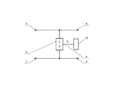
- Fig. 1 shows the design of an overvoltage protection with a two-pole protection element, a temperature dependent fuse and status indicator linked to each other with a thermal link.
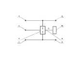
- Fig. 2 shows the design of an overvoltage protection with a two-pole protection element, a status indicator linked to each other with a thermal link without the temperature-dependent fuse.
- Fig. 3 shows the design of an overvoltage protection with a three-pole protection element and status indicator linked to each other using the thermal link without a temperature-dependent fuse.
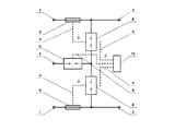
- Fig. 4 shows the design of an overvoltage protection with three two-pole protection members, two temperature-dependent fuses and a status indicator linked to each other using a thermal link.
- Fig. 5 shows the design of an overvoltage protection with three two-pole protection members, two temperature-dependent fuses and three status indicators linked via a thermal link to the respective protection component and/or temperature dependent fuse.
- the overvoltage protection comprises at least one protection element from the group of the two-pole protection component 6, two-pole protection component 6 complemented with a temperature dependent fuse 8, three-pole protection component 7.
- Indication of exceeded operating temperature according to the new solution consists of all protection components used in the specific overvoltage protection linked via a thermal link to a status indicator 10 which comprises a thermosensitive layer with irreversible change of colour in case the temperature of the damaged protection members of the specific overvoltage protection is exceeded.
- Fig. 1 shows overvoltage protection which comprises one two-pole protection element 6 connected with its one end between the first input terminal 1 and the first output terminal 2. With its second end the two-pole protection component 6 is connected via a temperature dependent fuse 8 to the second input terminal 3 and, at the same time, it is interconnected with the second output terminal 4.
- a status indicator 10 is linked to both overvoltage protection elements via a thermal link 9. Similar design is indicated in Fig. 2 with a temperature-dependent fuse 8 left out.
- Fig. 3 shows the option of the design with a three-pole protection element 7, the medium pole of which is connected to the third input terminal 5 and to which a status indicator 10 is linked to the thermal link 9.
- the overvoltage protection in this figure comprises three two-pole protection members 6, connected in a star without an output common junction.
- Two protection two-pole elements 6 are connected in series and connected with their one external end via temperature-dependent fuses 8 to the first input terminal 1, or the second input terminal 3 and, at the same time, they are interconnected with the first output terminal 2, or the second output terminal 4.
- the third protection two-pole element 6 is connected between their common point and the third input terminal 5. All these protection components are linked via the thermal link 9 to the single status indicator 10.
- Fig. 5 is an option of the design with each protection component linked via the thermal link 9 to a separate status indicator 10, whereas protective two-pole elements 6 complemented with dependent fuses 8 are considered to be one protection component.
- the thermosensitive layer of the status indicator 10 may consist of a paint or a film, with an advantage in a form of a self-adhesive label. It is either applied directly onto the protection components of the specific overvoltage protection, or it can be created on the thermo-conductive substrate positioned in a close distance from the specific protection member. Should a temperature-dependent fuse 8 be used, the status indicator 10 should be located directly onto it.
- the temperature at which the protection member is damaged is known. Based on the temperature a specific thermosensitive layer of the status indicator 10 is chosen. If this temperature is exceeded, the protection member is damaged, and the thermosensitive layer of the status indicator 10 will permanently change its colour. It indicates the fact that the permitted temperature was exceeded, at which the temperature-dependent fuse disconnects and/or the protection member is damaged.
- the protection component consisting of a varistor is connected in series in compliance with standards with the temperature dependent fuse.
- the thermal link 9 is then carried out between all elements in such a manner that they are located next to each other and touch each other.
- the overvoltage protection with indication of exceeded operating temperature is a product which can be used where protection of electronic equipment and instruments from overvoltage is necessary, e.g. in installations of modern LED lighting systems, converters of photovoltaic systems, etc.
Landscapes
- Physics & Mathematics (AREA)
- Engineering & Computer Science (AREA)
- Microelectronics & Electronic Packaging (AREA)
- Electromagnetism (AREA)
- General Physics & Mathematics (AREA)
- Emergency Protection Circuit Devices (AREA)
- Fuses (AREA)
Abstract
L'invention concerne une protection de surtension avec indication de température de fonctionnement dépassée, la protection de surtension comprenant au moins un élément de protection parmi le groupe comportant un élément de protection bipolaire (6), un élément de protection bipolaire (6) étant complété par un fusible dépendant de la température (8), et un élément de protection tripolaire (7). Tous les éléments de protection utilisés dans la protection de surtension de l'invention sont reliés par l'intermédiaire d'une liaison thermique (9) à l'indicateur d'état (10) comportant une couche thermosensible à changement irréversible de couleur dans le cas où une température des éléments de protection détruits de la protection de surtension est dépassée.
Priority Applications (3)
| Application Number | Priority Date | Filing Date | Title |
|---|---|---|---|
| CN201790001034.XU CN209639858U (zh) | 2016-05-03 | 2017-05-03 | 具有超过作业温度指示的过电压保护装置 |
| US16/097,627 US20190154520A1 (en) | 2016-05-03 | 2017-05-03 | Overvoltage protection with indication of exceeded operating temperature |
| EP17792583.1A EP3452794A4 (fr) | 2016-05-03 | 2017-05-03 | Protection de surtension avec indication de température de fonctionnement dépassée |
Applications Claiming Priority (2)
| Application Number | Priority Date | Filing Date | Title |
|---|---|---|---|
| CZ20163234 | 2016-05-03 | ||
| CZPUV2016-32340 | 2016-05-03 |
Publications (1)
| Publication Number | Publication Date |
|---|---|
| WO2017191566A1 true WO2017191566A1 (fr) | 2017-11-09 |
Family
ID=60202826
Family Applications (1)
| Application Number | Title | Priority Date | Filing Date |
|---|---|---|---|
| PCT/IB2017/052554 Ceased WO2017191566A1 (fr) | 2016-05-03 | 2017-05-03 | Protection de surtension avec indication de température de fonctionnement dépassée |
Country Status (1)
| Country | Link |
|---|---|
| WO (1) | WO2017191566A1 (fr) |
Cited By (1)
| Publication number | Priority date | Publication date | Assignee | Title |
|---|---|---|---|---|
| CN114096820A (zh) * | 2019-03-07 | 2022-02-25 | 泰连服务有限公司 | 用于电端子的隔离温度感测 |
Citations (6)
| Publication number | Priority date | Publication date | Assignee | Title |
|---|---|---|---|---|
| US3002385A (en) * | 1960-02-12 | 1961-10-03 | Pyrodyne Inc | Temperature indicator |
| US3254179A (en) * | 1964-01-07 | 1966-05-31 | Northern Electric Co | Mounting for communication line protector |
| US5502612A (en) * | 1992-07-08 | 1996-03-26 | Joslyn Manufacturing Company | Secondary surge arrester with isolating and indicating features |
| EP0915544B1 (fr) * | 1997-11-08 | 2003-12-03 | ABB Schweiz AG | Dérivateur de surtensions, muni d'un dispositif indiquant un courant de défaut |
| JP2005150657A (ja) * | 2003-11-20 | 2005-06-09 | Central Japan Railway Co | 劣化表示機能付き保安器 |
| US20090009921A1 (en) * | 2007-07-02 | 2009-01-08 | Phoenix Contact Gmbh & Co. Kg | Overvoltage protection element |
-
2017
- 2017-05-03 WO PCT/IB2017/052554 patent/WO2017191566A1/fr not_active Ceased
Patent Citations (6)
| Publication number | Priority date | Publication date | Assignee | Title |
|---|---|---|---|---|
| US3002385A (en) * | 1960-02-12 | 1961-10-03 | Pyrodyne Inc | Temperature indicator |
| US3254179A (en) * | 1964-01-07 | 1966-05-31 | Northern Electric Co | Mounting for communication line protector |
| US5502612A (en) * | 1992-07-08 | 1996-03-26 | Joslyn Manufacturing Company | Secondary surge arrester with isolating and indicating features |
| EP0915544B1 (fr) * | 1997-11-08 | 2003-12-03 | ABB Schweiz AG | Dérivateur de surtensions, muni d'un dispositif indiquant un courant de défaut |
| JP2005150657A (ja) * | 2003-11-20 | 2005-06-09 | Central Japan Railway Co | 劣化表示機能付き保安器 |
| US20090009921A1 (en) * | 2007-07-02 | 2009-01-08 | Phoenix Contact Gmbh & Co. Kg | Overvoltage protection element |
Non-Patent Citations (1)
| Title |
|---|
| See also references of EP3452794A4 * |
Cited By (1)
| Publication number | Priority date | Publication date | Assignee | Title |
|---|---|---|---|---|
| CN114096820A (zh) * | 2019-03-07 | 2022-02-25 | 泰连服务有限公司 | 用于电端子的隔离温度感测 |
Similar Documents
| Publication | Publication Date | Title |
|---|---|---|
| CA2115340C (fr) | Circuit de protection contre les surtensions et boitier | |
| US4964160A (en) | Protector device | |
| US4142151A (en) | Failed diode indicator | |
| CN103703637A (zh) | 具有用于监控过电压保护元件的测量装置的过电压保护设备 | |
| CN105190790B (zh) | 带老化警报的变阻器 | |
| US20190154520A1 (en) | Overvoltage protection with indication of exceeded operating temperature | |
| GB2093647A (en) | Voltage-limiting circuit | |
| EP3726682A1 (fr) | Unité de sécurité | |
| WO2017191566A1 (fr) | Protection de surtension avec indication de température de fonctionnement dépassée | |
| CN107452546B (zh) | 一种节省空间的隔离避雷器 | |
| CN109687420B (zh) | 安装空间有限的过压保护模块 | |
| CN1132195C (zh) | 具有过载保护的混合电路装置 | |
| CN106451344A (zh) | 一种保护电路装置 | |
| CN215498269U (zh) | 一种开关电源防雷电路和开关电源 | |
| CN105981251B (zh) | 一种带漏电流切断的过电压保护装置 | |
| RU2145759C1 (ru) | Устройство защиты от перенапряжений в сети питания с постоянным напряжением | |
| CN213937430U (zh) | 一种过电压保护电路及电子设备 | |
| US11121546B2 (en) | Protection ensemble | |
| Finis et al. | Safety-Related Functions and Status Indication for Surge Protective Devices for the Use in MCR Applications | |
| CN222797741U (zh) | 一种监测电路、散热装置和整机系统 | |
| US12283810B2 (en) | Interference filter arrangement with surge protection | |
| CN112260248A (zh) | 一种过电压保护电路及电子设备 | |
| Finis et al. | Monitoring, diagnosis and safety-related functions for surge protective devices for the use in MCR applications | |
| CN219086800U (zh) | 一种浪涌保护电路及开关电源 | |
| CA3245241A1 (fr) | Dispositifs de protection contre les surtensions comprenant des varistances |
Legal Events
| Date | Code | Title | Description |
|---|---|---|---|
| NENP | Non-entry into the national phase |
Ref country code: DE |
|
| 121 | Ep: the epo has been informed by wipo that ep was designated in this application |
Ref document number: 17792583 Country of ref document: EP Kind code of ref document: A1 |
|
| ENP | Entry into the national phase |
Ref document number: 2017792583 Country of ref document: EP Effective date: 20181203 |