WO2017191679A1 - リチウムイオン電池パック - Google Patents
リチウムイオン電池パック Download PDFInfo
- Publication number
- WO2017191679A1 WO2017191679A1 PCT/JP2016/063596 JP2016063596W WO2017191679A1 WO 2017191679 A1 WO2017191679 A1 WO 2017191679A1 JP 2016063596 W JP2016063596 W JP 2016063596W WO 2017191679 A1 WO2017191679 A1 WO 2017191679A1
- Authority
- WO
- WIPO (PCT)
- Prior art keywords
- battery module
- switch
- lithium ion
- battery
- heater
- Prior art date
- Legal status (The legal status is an assumption and is not a legal conclusion. Google has not performed a legal analysis and makes no representation as to the accuracy of the status listed.)
- Ceased
Links
Images



Classifications
-
- H—ELECTRICITY
- H01—ELECTRIC ELEMENTS
- H01M—PROCESSES OR MEANS, e.g. BATTERIES, FOR THE DIRECT CONVERSION OF CHEMICAL ENERGY INTO ELECTRICAL ENERGY
- H01M10/00—Secondary cells; Manufacture thereof
- H01M10/60—Heating or cooling; Temperature control
- H01M10/61—Types of temperature control
- H01M10/615—Heating or keeping warm
-
- B—PERFORMING OPERATIONS; TRANSPORTING
- B60—VEHICLES IN GENERAL
- B60K—ARRANGEMENT OR MOUNTING OF PROPULSION UNITS OR OF TRANSMISSIONS IN VEHICLES; ARRANGEMENT OR MOUNTING OF PLURAL DIVERSE PRIME-MOVERS IN VEHICLES; AUXILIARY DRIVES FOR VEHICLES; INSTRUMENTATION OR DASHBOARDS FOR VEHICLES; ARRANGEMENTS IN CONNECTION WITH COOLING, AIR INTAKE, GAS EXHAUST OR FUEL SUPPLY OF PROPULSION UNITS IN VEHICLES
- B60K1/00—Arrangement or mounting of electrical propulsion units
- B60K1/04—Arrangement or mounting of electrical propulsion units of the electric storage means for propulsion
-
- B—PERFORMING OPERATIONS; TRANSPORTING
- B60—VEHICLES IN GENERAL
- B60L—PROPULSION OF ELECTRICALLY-PROPELLED VEHICLES; SUPPLYING ELECTRIC POWER FOR AUXILIARY EQUIPMENT OF ELECTRICALLY-PROPELLED VEHICLES; ELECTRODYNAMIC BRAKE SYSTEMS FOR VEHICLES IN GENERAL; MAGNETIC SUSPENSION OR LEVITATION FOR VEHICLES; MONITORING OPERATING VARIABLES OF ELECTRICALLY-PROPELLED VEHICLES; ELECTRIC SAFETY DEVICES FOR ELECTRICALLY-PROPELLED VEHICLES
- B60L1/00—Supplying electric power to auxiliary equipment of vehicles
- B60L1/003—Supplying electric power to auxiliary equipment of vehicles to auxiliary motors, e.g. for pumps, compressors
-
- B—PERFORMING OPERATIONS; TRANSPORTING
- B60—VEHICLES IN GENERAL
- B60L—PROPULSION OF ELECTRICALLY-PROPELLED VEHICLES; SUPPLYING ELECTRIC POWER FOR AUXILIARY EQUIPMENT OF ELECTRICALLY-PROPELLED VEHICLES; ELECTRODYNAMIC BRAKE SYSTEMS FOR VEHICLES IN GENERAL; MAGNETIC SUSPENSION OR LEVITATION FOR VEHICLES; MONITORING OPERATING VARIABLES OF ELECTRICALLY-PROPELLED VEHICLES; ELECTRIC SAFETY DEVICES FOR ELECTRICALLY-PROPELLED VEHICLES
- B60L58/00—Methods or circuit arrangements for monitoring or controlling batteries or fuel cells, specially adapted for electric vehicles
- B60L58/10—Methods or circuit arrangements for monitoring or controlling batteries or fuel cells, specially adapted for electric vehicles for monitoring or controlling batteries
- B60L58/18—Methods or circuit arrangements for monitoring or controlling batteries or fuel cells, specially adapted for electric vehicles for monitoring or controlling batteries of two or more battery modules
- B60L58/21—Methods or circuit arrangements for monitoring or controlling batteries or fuel cells, specially adapted for electric vehicles for monitoring or controlling batteries of two or more battery modules having the same nominal voltage
-
- B—PERFORMING OPERATIONS; TRANSPORTING
- B60—VEHICLES IN GENERAL
- B60L—PROPULSION OF ELECTRICALLY-PROPELLED VEHICLES; SUPPLYING ELECTRIC POWER FOR AUXILIARY EQUIPMENT OF ELECTRICALLY-PROPELLED VEHICLES; ELECTRODYNAMIC BRAKE SYSTEMS FOR VEHICLES IN GENERAL; MAGNETIC SUSPENSION OR LEVITATION FOR VEHICLES; MONITORING OPERATING VARIABLES OF ELECTRICALLY-PROPELLED VEHICLES; ELECTRIC SAFETY DEVICES FOR ELECTRICALLY-PROPELLED VEHICLES
- B60L58/00—Methods or circuit arrangements for monitoring or controlling batteries or fuel cells, specially adapted for electric vehicles
- B60L58/10—Methods or circuit arrangements for monitoring or controlling batteries or fuel cells, specially adapted for electric vehicles for monitoring or controlling batteries
- B60L58/24—Methods or circuit arrangements for monitoring or controlling batteries or fuel cells, specially adapted for electric vehicles for monitoring or controlling batteries for controlling the temperature of batteries
- B60L58/27—Methods or circuit arrangements for monitoring or controlling batteries or fuel cells, specially adapted for electric vehicles for monitoring or controlling batteries for controlling the temperature of batteries by heating
-
- H—ELECTRICITY
- H01—ELECTRIC ELEMENTS
- H01M—PROCESSES OR MEANS, e.g. BATTERIES, FOR THE DIRECT CONVERSION OF CHEMICAL ENERGY INTO ELECTRICAL ENERGY
- H01M10/00—Secondary cells; Manufacture thereof
- H01M10/05—Accumulators with non-aqueous electrolyte
- H01M10/052—Li-accumulators
- H01M10/0525—Rocking-chair batteries, i.e. batteries with lithium insertion or intercalation in both electrodes; Lithium-ion batteries
-
- H—ELECTRICITY
- H01—ELECTRIC ELEMENTS
- H01M—PROCESSES OR MEANS, e.g. BATTERIES, FOR THE DIRECT CONVERSION OF CHEMICAL ENERGY INTO ELECTRICAL ENERGY
- H01M10/00—Secondary cells; Manufacture thereof
- H01M10/60—Heating or cooling; Temperature control
- H01M10/62—Heating or cooling; Temperature control specially adapted for specific applications
- H01M10/625—Vehicles
-
- H—ELECTRICITY
- H01—ELECTRIC ELEMENTS
- H01M—PROCESSES OR MEANS, e.g. BATTERIES, FOR THE DIRECT CONVERSION OF CHEMICAL ENERGY INTO ELECTRICAL ENERGY
- H01M10/00—Secondary cells; Manufacture thereof
- H01M10/60—Heating or cooling; Temperature control
- H01M10/63—Control systems
-
- H—ELECTRICITY
- H01—ELECTRIC ELEMENTS
- H01M—PROCESSES OR MEANS, e.g. BATTERIES, FOR THE DIRECT CONVERSION OF CHEMICAL ENERGY INTO ELECTRICAL ENERGY
- H01M10/00—Secondary cells; Manufacture thereof
- H01M10/60—Heating or cooling; Temperature control
- H01M10/65—Means for temperature control structurally associated with the cells
- H01M10/657—Means for temperature control structurally associated with the cells by electric or electromagnetic means
- H01M10/6571—Resistive heaters
-
- H—ELECTRICITY
- H01—ELECTRIC ELEMENTS
- H01M—PROCESSES OR MEANS, e.g. BATTERIES, FOR THE DIRECT CONVERSION OF CHEMICAL ENERGY INTO ELECTRICAL ENERGY
- H01M50/00—Constructional details or processes of manufacture of the non-active parts of electrochemical cells other than fuel cells, e.g. hybrid cells
- H01M50/20—Mountings; Secondary casings or frames; Racks, modules or packs; Suspension devices; Shock absorbers; Transport or carrying devices; Holders
- H01M50/204—Racks, modules or packs for multiple batteries or multiple cells
-
- H—ELECTRICITY
- H02—GENERATION; CONVERSION OR DISTRIBUTION OF ELECTRIC POWER
- H02J—ELECTRIC POWER NETWORKS; CIRCUIT ARRANGEMENTS OR SYSTEMS FOR SUPPLYING OR DISTRIBUTING ELECTRIC POWER; SYSTEMS FOR STORING ELECTRIC ENERGY
- H02J7/00—Circuit arrangements for charging or discharging batteries or for supplying loads from batteries
- H02J7/34—Parallel operation in networks using both storage and other DC sources, e.g. providing buffering
-
- B—PERFORMING OPERATIONS; TRANSPORTING
- B60—VEHICLES IN GENERAL
- B60L—PROPULSION OF ELECTRICALLY-PROPELLED VEHICLES; SUPPLYING ELECTRIC POWER FOR AUXILIARY EQUIPMENT OF ELECTRICALLY-PROPELLED VEHICLES; ELECTRODYNAMIC BRAKE SYSTEMS FOR VEHICLES IN GENERAL; MAGNETIC SUSPENSION OR LEVITATION FOR VEHICLES; MONITORING OPERATING VARIABLES OF ELECTRICALLY-PROPELLED VEHICLES; ELECTRIC SAFETY DEVICES FOR ELECTRICALLY-PROPELLED VEHICLES
- B60L2240/00—Control parameters of input or output; Target parameters
- B60L2240/10—Vehicle control parameters
- B60L2240/36—Temperature of vehicle components or parts
-
- B—PERFORMING OPERATIONS; TRANSPORTING
- B60—VEHICLES IN GENERAL
- B60L—PROPULSION OF ELECTRICALLY-PROPELLED VEHICLES; SUPPLYING ELECTRIC POWER FOR AUXILIARY EQUIPMENT OF ELECTRICALLY-PROPELLED VEHICLES; ELECTRODYNAMIC BRAKE SYSTEMS FOR VEHICLES IN GENERAL; MAGNETIC SUSPENSION OR LEVITATION FOR VEHICLES; MONITORING OPERATING VARIABLES OF ELECTRICALLY-PROPELLED VEHICLES; ELECTRIC SAFETY DEVICES FOR ELECTRICALLY-PROPELLED VEHICLES
- B60L2240/00—Control parameters of input or output; Target parameters
- B60L2240/40—Drive Train control parameters
- B60L2240/54—Drive Train control parameters related to batteries
- B60L2240/545—Temperature
-
- Y—GENERAL TAGGING OF NEW TECHNOLOGICAL DEVELOPMENTS; GENERAL TAGGING OF CROSS-SECTIONAL TECHNOLOGIES SPANNING OVER SEVERAL SECTIONS OF THE IPC; TECHNICAL SUBJECTS COVERED BY FORMER USPC CROSS-REFERENCE ART COLLECTIONS [XRACs] AND DIGESTS
- Y02—TECHNOLOGIES OR APPLICATIONS FOR MITIGATION OR ADAPTATION AGAINST CLIMATE CHANGE
- Y02E—REDUCTION OF GREENHOUSE GAS [GHG] EMISSIONS, RELATED TO ENERGY GENERATION, TRANSMISSION OR DISTRIBUTION
- Y02E60/00—Enabling technologies; Technologies with a potential or indirect contribution to GHG emissions mitigation
- Y02E60/10—Energy storage using batteries
-
- Y—GENERAL TAGGING OF NEW TECHNOLOGICAL DEVELOPMENTS; GENERAL TAGGING OF CROSS-SECTIONAL TECHNOLOGIES SPANNING OVER SEVERAL SECTIONS OF THE IPC; TECHNICAL SUBJECTS COVERED BY FORMER USPC CROSS-REFERENCE ART COLLECTIONS [XRACs] AND DIGESTS
- Y02—TECHNOLOGIES OR APPLICATIONS FOR MITIGATION OR ADAPTATION AGAINST CLIMATE CHANGE
- Y02T—CLIMATE CHANGE MITIGATION TECHNOLOGIES RELATED TO TRANSPORTATION
- Y02T10/00—Road transport of goods or passengers
- Y02T10/60—Other road transportation technologies with climate change mitigation effect
- Y02T10/70—Energy storage systems for electromobility, e.g. batteries
Definitions
- the embodiment of the present invention relates to a lithium ion battery pack for starting an engine.
- LiB lithium ion battery
- the merit of replacing the lead battery with LiB is not only the abolition of harmful metals but also other merit.
- the allowable CO 2 emissions of vehicles are limited, so various types of electrification and vehicle fuel efficiency improvements are being made.
- An example is a micro-hybrid using a conventional combustion engine.
- the micro hybrid since the engine is frequently restarted, a battery that is resistant to deep discharge is required.
- a battery with high charge acceptance performance is required.
- LiB is superior to lead batteries in terms of resistance to deep discharge and charge acceptance performance.
- the vehicle system can be reduced in weight and size by switching the lead battery to LiB.
- LiB The problem of LiB is that, as a whole property of LiB, the use of an organic solvent for the electrolytic solution increases the viscosity of the electrolytic solution at a low temperature and greatly increases the internal resistance. As a result, LiB has a lower output at a lower temperature than the lead battery, and the cold crank performance of the engine is weakened. If the capacity of LiB is increased to prevent this, LiB loses the advantages of small size and light weight, and this is a problem for the spread of LiB.
- the problem to be solved by the embodiments of the present invention is to provide a lithium-ion battery pack for starting an engine that improves low-temperature output performance.
- the lithium ion battery pack according to the present embodiment is mounted on a vehicle (automobile).
- the lithium ion battery pack includes a first battery module, a second battery module, a heater, a first switch, a second switch, and a third switch.
- the first battery module is composed of one or more lithium ion batteries.
- the second battery module is connected in parallel with the first battery module and is composed of one or more lithium ion batteries.
- the heater is electrically connected to the second battery module, is disposed in proximity to the first battery module, and heats the first battery module.
- the first switch turns on or off the power supply to the outside by the first battery module, and turns on the power supply to the outside by the first battery module to start the engine.
- the second switch switches on or off the power supply to the outside by the second battery module.
- the third switch turns on or off the power supply to the heater by the second battery module, and turns on the power supply to the heater before starting the engine.
- FIG. 1 is a schematic diagram illustrating an example of a lithium ion battery pack according to an embodiment.
- FIG. 2 is a table showing an example operation of the lithium ion battery pack according to the embodiment.
- FIG. 3 is a table showing another example operation of the lithium ion battery pack according to the embodiment.
- FIG. 4 is a table showing still another example operation of the lithium ion battery pack according to the embodiment.
- FIG. 1 is a schematic diagram illustrating an example of a lithium ion battery pack 1 according to the embodiment.
- the lithium ion battery pack 1 is mounted on a vehicle mainly for the purpose of starting an engine and supplying electric power to in-vehicle accessories.
- the positive electrode terminal 10 of the lithium ion battery pack 1 is connected to a network that electrically connects each element mounted on the vehicle. Thereby, the lithium ion battery pack 1 is electrically connected to the alternator 2, the starter 3, and the general load 4.
- the alternator 2 is a generator.
- the starter 3 is a motor used when starting the engine.
- the general load 4 is, for example, a vehicle-mounted auxiliary machine including at least one of equipment and external accessories provided in a vehicle that operates by electricity.
- the lithium ion battery pack 1 includes a first battery module 11, a second battery module 12, a heater 13, a first switch 14, a second switch 15, a third switch 16, a temperature sensor 17, and a control unit 18. Have. These elements are electrically connected. The lithium ion battery pack 1 accommodates these elements in a case.
- the first battery module 11 is composed of one or more lithium ion batteries (cells).
- the first battery module is, for example, 12V.
- the positive electrode of the first battery module 11 is electrically connected to the positive electrode terminal 10 via a first switch 14 described later.
- the negative electrode of the first battery module 11 is grounded.
- the second battery module 12 is composed of one or more lithium ion batteries.
- the output density or energy density of the second battery module 12 may be the same as or different from the output density or energy density of the first battery module 11, and is not particularly limited.
- the second battery module 12 is, for example, 12V.
- the second battery module 12 is connected in parallel with the first battery module 11.
- the positive electrode of the second battery module 12 is electrically connected to the positive electrode terminal 10 via a second switch 15 described later.
- the negative electrode of the second battery module 12 is grounded.
- the heater 13 is electrically connected to the second battery module 12.
- one end of the heater 13 is electrically connected to the positive electrode of the second battery module 12 via a third switch 16 described later.
- the other end of the heater 13 is grounded.
- the heater 13 is disposed in the vicinity of the first battery module 11. Thereby, the heater 13 heats the first battery module 11. Note that the positional relationship of the heater 13 with respect to the first battery module 11 can be appropriately adjusted within a range in which the heater 13 can heat the first battery module 11.
- the first switch (relay) 14 is disposed between the positive electrode of the first battery module 11 and the positive electrode terminal 10.
- the first switch 14 switches the electrical connection state between the positive electrode of the first battery module 11 and the positive electrode terminal 10 to on (valid) or off (invalid). Accordingly, the first switch 14 switches on or off the power supply to the outside by the first battery module 11.
- the switching of the first switch 14 on or off will be described later, as an example, the first switch 14 turns on the external power supply by the first battery module 11 to start the engine.
- the second switch (relay) 15 is disposed between the positive electrode of the second battery module 12 and the positive electrode terminal 10.
- the second switch 15 switches the electrical connection state between the positive electrode of the second battery module 12 and the positive electrode terminal 10 to on or off. Accordingly, the second switch 15 switches on or off the power supply to the outside by the second battery module 12. The on / off switching of the second switch 15 will be described later.
- the third switch (relay) 16 is disposed between one end of the heater 13 and the positive electrode of the second battery module 12.
- the third switch 16 switches the electrical connection state between one end of the heater 13 and the positive electrode of the second battery module 12 to on or off. Accordingly, the third switch 16 turns on or off the power supply to the heater 13 by the second battery module 12. The switching of the third switch 16 on or off will be described later. As an example, the third switch 16 turns on the power supply to the heater 13 before starting the engine.
- the temperature sensor 17 is disposed in the vicinity of the first battery module 11.
- the temperature sensor 17 may or may not be in contact with the first battery module 11.
- the temperature sensor 17 measures the temperature of the first battery module 11.
- the control unit 18 controls each element constituting the lithium ion battery pack 1. For example, the control unit 18 switches the first switch 14 on or off. The control unit 18 switches the second switch 15 on or off. The control unit 18 switches the third switch 16 on or off. The control unit 18 receives temperature information measured by the temperature sensor 17 (hereinafter referred to as temperature information). The control unit 18 switches the state of each switch based on the temperature information. Control based on the temperature information by the control unit 18 will be described later.
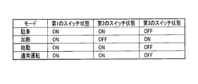
- FIG. 2 is a table showing an exemplary operation of the lithium ion battery pack 1.
- FIG. 2 shows the state of each switch in each mode of the vehicle.
- the parking mode is a mode in which the engine is stopped.
- the heating mode is a mode in which the heater 13 is heated before the engine is started.
- the heating mode is, for example, a mode after an engine start trigger is input.
- the start mode is a mode when the engine is started.
- the normal operation mode is a mode in which the vehicle is running after the engine is started.
- each switch in the parking mode will be described.
- the first switch 14 is off, the second switch 15 is on, and the third switch 16 is off.
- the first battery module 11 does not supply power to the general load 4, but the second battery module 12 can supply power to the general load 4. Therefore, the general load 4 can be used even when the engine is stopped.
- each switch in the heating mode When transiting from the parking mode to the heating mode, the state of each switch is switched as follows based on the control of the control unit 18.
- the first switch 14 is switched from off to on based on the control of the control unit 18.
- the second switch 15 switches from on to off based on the control of the control unit 18.
- the third switch 16 switches from off to on based on the control of the control unit 18.
- the second battery module 12 can supply power to the heater 13 without supplying power to the outside. Therefore, the first battery module 11 is heated by the heater 13.
- the state of each switch in the start mode will be described. At the time of transition from the heating mode to the start mode, the state of each switch is switched as follows based on the control of the control unit 18.
- the control unit 18 refers to the temperature information and determines whether or not the temperature of the first battery module 11 is equal to or higher than a threshold value.
- the threshold is a temperature at which the first battery module 11 can obtain output characteristics that can supply power that can start the starter 3. This is because the output characteristics of the first battery module 11 increase as the temperature increases.
- the threshold value can be changed as appropriate.
- the control unit 18 When the temperature of the first battery module 11 is lower than the threshold value, the control unit 18 maintains the heating mode. That is, the third switch 16 is kept on. When the temperature of the first battery module 11 is equal to or higher than the threshold, the third switch 16 is switched from on to off based on the control of the control unit 18. Thereby, the second battery module 12 does not supply power to the heater 13.
- the reason why the third switch 16 is switched from on to off is that it is not necessary to heat the first battery module 11 any more if the output characteristics of the first battery module 11 are sufficient to start the starter 3. It is. Note that the first switch 14 is kept on, and the second switch 15 is kept off. Thereby, in the start mode, the first battery module 11 supplies power to the starter 3. Thereby, the starter 3 is started and the engine is started according to the operation of the starter 3.
- the first battery module 11 can also supply power to the general load 4.
- each switch in the normal operation mode When switching from the start mode to the normal operation mode, the state of each switch is switched as follows based on the control of the control unit 18.
- the second switch 15 is switched from off to on based on the control of the control unit 18.
- the first switch 14 is kept on, and the third switch 16 is kept off.
- the first battery module 11 and the second battery module 12 supply power to the general load 4. Therefore, the general load 4 can be used during the normal operation mode.
- FIG. 3 is a table showing another example operation of the lithium ion battery pack 1.
- the first switch 14 is off in the example shown in FIG. 2, but the first switch 14 is on in the example shown in FIG.
- the lithium ion battery pack 1 of the example shown in FIG. 3 can supply power to the general load 4 for a longer time than the lithium ion battery pack 1 of the example shown in FIG.
- the second switch 15 is off in the example shown in FIG. 2, but the second switch 15 is on in the example shown in FIG. Thereby, in the start mode, the second battery module 12 can supply power to the general load 4. Therefore, the general load 4 is stably supplied with power from the lithium ion battery pack 1.
- FIG. 4 is a table showing still another example operation of the lithium ion battery pack 1.
- the second switch 15 is off in the example shown in FIG. 2, but in the example shown in FIG. 4, the second switch 15 is on as in the example shown in FIG.
- the output performance of the lithium ion battery pack 1 does not deteriorate even at low temperatures. Therefore, the lithium ion battery pack 1 can prevent the engine cold crank performance from being lowered.
- the lithium ion battery pack 1 for engine starting which improves low-temperature output performance can be provided.
- the capacity of the second battery module 12 is such that the heater 13 supplies power to the heater 13 for a predetermined period of time in order to raise the temperature of the first battery module 11 to a threshold value (predetermined temperature). Sufficient capacity. Thereby, the heater 13 stably supplies power for heating the first battery module 11 from the second battery module 12.
- the first battery module 11 and the second battery module 12 are constituted by battery modules having the same voltage characteristics. Further, the output density of the first battery module 11 is different from the output density of the second battery module 12. Specifically, the first battery module 11 has a higher power density than the second battery module 12. High power density means that the instantaneous output capability of energy is high. In this example, the resistance value of the first battery module 11 is lower than the resistance value of the second battery module 12.
- the battery module that supplies power to the starter 3 when the engine is started is required to output instantaneously in a short time of, for example, 1 second or less.
- the first battery module 11 configured as described above can supply an instantaneous output in a shorter time than the second battery module 12.
- the lithium ion battery pack 1 can efficiently start the engine even at a low temperature.
- the first battery module 11 and the second battery module 12 are constituted by battery modules having the same voltage characteristics. Further, the energy density of the first battery module 11 is different from the energy density of the second battery module 12. Specifically, the second battery module 12 has a higher energy density than the first battery module 11. High energy density means that the continuous output capability of energy is high.
- the battery module that supplies power to the heater 13 is required to output continuously until the first battery module 11 reaches a predetermined temperature.
- the second battery module 12 configured as described above can supply electric power to the heater 13 with high energy density. Thereby, the heater 13 can heat the 1st battery module 11 stably.
- the lithium ion battery pack 1 can start the engine efficiently even at a low temperature.
- the second modification may be combined with the first modification. That is, the first battery module 11 is configured to have a higher output density than the second battery module 12, and the second battery module 12 has a higher energy density than the first battery module 11. May be configured.
- the lithium ion battery pack 1 can obtain both the effects described in the first modification and the operations and effects described in the second modification.
- the first switch 14, the second switch 15, and the third switch 16 may be controlled by a control unit different from the control unit 18 included in the lithium ion battery pack 1.
- the first switch 14, the second switch 15, and the third switch 16 may be controlled by another control unit (not shown) that controls elements mounted on the vehicle.
- one or two of the first switch 14, the second switch 15, and the third switch 16 may be controlled by the control unit 18.
- one or two switches that are not controlled by the control unit 18 among the first switch 14, the second switch 15, and the third switch 16 may be controlled by another control unit.
- a second battery module 11 (40 Ah) in which 5 pieces of b were connected in series was prepared.
- a first switch (relay) 14 is connected to the first battery module 11, a second switch (relay) 15 is connected to the second battery module 12, and the first battery module 11 and the second battery module 11 are connected to the second battery module 12. Battery modules 12 were connected in parallel.
- the heater 13 was disposed so as to cover the cell surface of the first battery module 11 with the surface of the 1000 W flat heater 13. Further, the heater 13 is connected to the second battery module 12 via the third switch (relay) 16 so that the power can be taken from the second battery module 12.
- the lithium ion battery pack 1 configured as described above was examined. The lithium ion battery pack 1 is connected to a network connected to the alternator 2, the starter 3, and the general load 4, and starts the engine.
- a battery C in which five high-capacity type cells c having the same total capacity of 50 Ah and 2.4 V were connected in series was examined.
- the first switch 14 is off, the second switch 15 is on, and the third switch 16 is off.
- the first switch 14 is turned on so that electric power can be supplied to the general load 4, the second switch 15 is turned off, the third switch 16 is turned on, and the first battery module is turned on. 11 is heated for 60 seconds. It was calculated that the temperature of the first battery module 11 was changed from ⁇ 30 ° C. to ⁇ 10 ° C. by heating.
- the third switch 16 when the third switch 16 is turned off, the first switch 14 is turned on, and the starter 3 of the engine is started, the first battery module 11 can discharge from the first battery module 11 at 500 A for about 5 seconds. Start.
- the current that can be discharged from the state of ⁇ 30 ° C. is about 200-300 A, which is insufficient for starting the engine.
- the second battery module 12 having a high energy density warms the first battery module 11 having a high output density as described above, even if the batteries have the same amount of energy (50 Ah, 12 V).
- cold cranking is possible.
Landscapes
- Engineering & Computer Science (AREA)
- Chemical & Material Sciences (AREA)
- Chemical Kinetics & Catalysis (AREA)
- General Chemical & Material Sciences (AREA)
- Electrochemistry (AREA)
- Manufacturing & Machinery (AREA)
- Power Engineering (AREA)
- Transportation (AREA)
- Mechanical Engineering (AREA)
- Sustainable Development (AREA)
- Life Sciences & Earth Sciences (AREA)
- Sustainable Energy (AREA)
- Electromagnetism (AREA)
- Combustion & Propulsion (AREA)
- Physics & Mathematics (AREA)
- Materials Engineering (AREA)
- Automation & Control Theory (AREA)
- Secondary Cells (AREA)
- Battery Mounting, Suspending (AREA)
- Hybrid Electric Vehicles (AREA)
- Arrangement Or Mounting Of Propulsion Units For Vehicles (AREA)
- Cooling, Air Intake And Gas Exhaust, And Fuel Tank Arrangements In Propulsion Units (AREA)
- Charge And Discharge Circuits For Batteries Or The Like (AREA)
Abstract
自動車に搭載されるリチウムイオン電池パックは、第1の電池モジュールと、第2の電池モジュールと、ヒータと、第1のスイッチと、第2のスイッチと、第3のスイッチとを備える。前記第1の電池モジュールは、前記第2の電池モジュールと並列接続されている。前記ヒータは、前記第2の電池モジュールと電気的に接続され、前記第1の電池モジュールに近接して配置され、前記第1の電池モジュールを加熱する。前記第1のスイッチは、前記第1の電池モジュールによる外部への電力供給をオンまたはオフに切り替え、エンジン始動のために前記第1の電池モジュールによる外部への電力供給をオンにする。前記第2のスイッチは、前記第2の電池モジュールによる外部への電力供給をオンまたはオフに切り替える。前記第3のスイッチは、前記第2の電池モジュールによる前記ヒータへの電力供給をオンまたはオフにし、エンジン始動前に前記ヒータへの電力供給をオンにする。
Description
本発明の実施形態は、エンジン始動用のリチウムイオン電池パックに関する。
車両が廃棄された時の廃棄物の量を減らすこと及び有害物質の使用を制限するため、2000年9月制定の2000/53/EC(ELV指令)が発行された。その中に、鉛は使用禁止材料に指定されていたが、同時に、鉛電池は例外製品に指定された。鉛電池の機能を完全に置き換えることができるものがないため、鉛電池は未だに車両に一般的に使用されている。その一方で、最近、リチウムイオン電池(以下、LiBという)に切り替える動きが少しずつ見えている。
鉛電池をLiBに代替するメリットは、有害金属の廃止だけではなく、それ以外のメリットも挙げられる。現在、欧州、米国等で車両の許容CO2の排出量が制限されているため、様々な電動化及び車両の燃費改善が行われている。一例として、従来の燃焼エンジンを使用しているマイクロハイブリッドである。マイクロハイブリッドでは、頻繁にエンジンを再始動するため、深い放電に強い電池が求められている。また、車両減速時のブレーキエネルギーを電池に貯める時、高い充電受入性能の電池が必要になってくる。深い放電への耐性と充電受入性能の観点で、鉛電池よりLiBの方が優れている。更に、常温ではLiBの方が鉛電池よりも出力が高いため、鉛電池をLiBに切り替えることによって、車両システムの軽量化と小型化も可能になる。
LiBの課題は、LiB全体の性質として、電解液に有機溶媒を使っていることにより、低温では電解液の粘度が増加し、内部抵抗が大きく上昇することである。その結果、LiBは、鉛電池に比べて低温での出力が低下し、エンジンのコールドクランク性能が弱くなる。これを防ぐためにLiBの容量を増大すると、LiBは小型軽量のメリットがなくなり、これがLiBの普及への課題になっている。
このように、今後、車両内で鉛電池を完全に無くす場合、LiBのみのシステムで低温出力性能を改善することが技術的な課題になっている。解決する手段として、電池を自らのエネルギーを使って加熱し、温度を上げることで出力を上げる方法は考案されている。しかしながら、その場合、LiBのSOC(State of Charge)が低下し、LiBの出力が下がる課題がある。
本発明の実施形態が解決しようとする課題は、低温出力性能を向上させるエンジン始動用のリチウムイオン電池パックを提供することにある。
本実施形態に係るリチウムイオン電池パックは車両(自動車)に搭載されるものである。リチウムイオン電池パックは、第1の電池モジュールと、第2の電池モジュールと、ヒータと、第1のスイッチと、第2のスイッチと、第3のスイッチとを備える。前記第1の電池モジュールは、1以上のリチウムイオン電池で構成されている。前記第2の電池モジュールは、前記第1の電池モジュールと並列接続され、1以上のリチウムイオン電池で構成されている。前記ヒータは、前記第2の電池モジュールと電気的に接続され、前記第1の電池モジュールに近接して配置され、前記第1の電池モジュールを加熱する。前記第1のスイッチは、前記第1の電池モジュールによる外部への電力供給をオンまたはオフに切り替え、エンジン始動のために前記第1の電池モジュールによる外部への電力供給をオンにする。前記第2のスイッチは、前記第2の電池モジュールによる外部への電力供給をオンまたはオフに切り替える。前記第3のスイッチは、前記第2の電池モジュールによる前記ヒータへの電力供給をオンまたはオフにし、エンジン始動前に前記ヒータへの電力供給をオンにする。
以下、実施形態について図面を参照して説明する。
図1は、実施形態に係るリチウムイオン電池パック1の一例を示す概略図である。
リチウムイオン電池パック1は、主として、エンジン始動及び車載補機類への電力供給を目的として車両に搭載される。
図1は、実施形態に係るリチウムイオン電池パック1の一例を示す概略図である。
リチウムイオン電池パック1は、主として、エンジン始動及び車載補機類への電力供給を目的として車両に搭載される。
リチウムイオン電池パック1の正極端子10は、車両に搭載されている各要素を電気的に接続するネットワークに接続されている。これにより、リチウムイオン電池パック1は、オルタネータ2、スタータ3及び一般負荷4に電気的に接続されている。オルタネータ2は、発電機である。スタータ3は、エンジン始動時に用いられるモータである。一般負荷4は、例えば、電気によって動作する車両に備え付けの設備及び外付けのアクセサリーのうちの少なくとも何れか一方を含む車載補機である。
リチウムイオン電池パック1は、第1の電池モジュール11、第2の電池モジュール12、ヒータ13、第1のスイッチ14、第2のスイッチ15、第3のスイッチ16、温度センサ17及び制御部18を有する。これらの要素は、電気的に接続されている。リチウムイオン電池パック1は、これらの要素をケース内に収容する。
第1の電池モジュール11は、1以上のリチウムイオン電池(セル)で構成されている。第1の電池モジュールは例えば12Vである。第1の電池モジュール11の正極は、後述する第1のスイッチ14を介して正極端子10と電気的に接続されている。他方、第1の電池モジュール11の負極は、接地されている。
第2の電池モジュール12は、1以上のリチウムイオン電池で構成されている。第2の電池モジュール12の出力密度またはエネルギー密度は、第1の電池モジュール11の出力密度またはエネルギー密度と同じであっても異なっていてもよく特に限定されない。第2の電池モジュール12は、例えば12Vである。第2の電池モジュール12は、第1の電池モジュール11と並列接続されている。第2の電池モジュール12の正極は、後述する第2のスイッチ15を介して正極端子10と電気的に接続されている。他方、第2の電池モジュール12の負極は、接地されている。
ヒータ13は、第2の電池モジュール12と電気的に接続されている。例えば、ヒータ13の一端は、後述する第3のスイッチ16を介して第2の電池モジュール12の正極と電気的に接続されている。ヒータ13の他端は、接地されている。ヒータ13は、第1の電池モジュール11に近接して配置されている。これにより、ヒータ13は、第1の電池モジュール11を加熱する。なお、第1の電池モジュール11に対するヒータ13の位置関係は、ヒータ13が第1の電池モジュール11を加熱できる範囲に適宜調整することができる。
第1のスイッチ(リレー)14は、第1の電池モジュール11の正極と正極端子10との間に配置されている。第1のスイッチ14は、第1の電池モジュール11の正極と正極端子10との間の電気的な接続状態をオン(有効)またはオフ(無効)に切り替える。これにより、第1のスイッチ14は、第1の電池モジュール11による外部への電力供給をオンまたはオフに切り替える。第1のスイッチ14のオンまたはオフの切り替えについては後述するが、一例として、第1のスイッチ14は、エンジン始動のために第1の電池モジュール11による外部への電力供給をオンにする。
第2のスイッチ(リレー)15は、第2の電池モジュール12の正極と正極端子10との間に配置されている。第2のスイッチ15は、第2の電池モジュール12の正極と正極端子10との間の電気的な接続状態をオンまたはオフに切り替える。これにより、第2のスイッチ15は、第2の電池モジュール12による外部への電力供給をオンまたはオフに切り替える。第2のスイッチ15のオンまたはオフの切り替えについては後述する。
第3のスイッチ(リレー)16は、ヒータ13の一端と第2の電池モジュール12の正極との間に配置されている。第3のスイッチ16は、ヒータ13の一端と第2の電池モジュール12の正極との間の電気的な接続状態をオンまたはオフに切り替える。これにより、第3のスイッチ16は、第2の電池モジュール12によるヒータ13への電力供給をオンまたはオフにする。第3のスイッチ16のオンまたはオフの切り替えについては後述するが、一例として、第3のスイッチ16は、エンジン始動前にヒータ13への電力供給をオンにする。
温度センサ17は、第1の電池モジュール11の近傍に配置されている。温度センサ17は、第1の電池モジュール11に接触していても、接触していなくてもよい。温度センサ17は、第1の電池モジュール11の温度を計測する。
制御部18は、リチウムイオン電池パック1を構成する各要素を制御する。例えば、制御部18は、第1のスイッチ14をオンまたはオフに切り替える。制御部18は、第2のスイッチ15をオンまたはオフに切り替える。制御部18は、第3のスイッチ16をオンまたはオフに切り替える。制御部18は、温度センサ17が計測した温度の情報(以下、温度情報という)を受信する。制御部18は、温度情報に基づいて各スイッチの状態を切り替える。制御部18による温度情報に基づいた制御については後述する。
次に、第1のスイッチ14、第2のスイッチ15及び第3のスイッチ16それぞれのオンまたはオフの切り替えについて説明する。
図2は、リチウムイオン電池パック1の一例となる動作を示す表である。図2は、車両の各モードにおける各スイッチの状態を示している。
図2は、リチウムイオン電池パック1の一例となる動作を示す表である。図2は、車両の各モードにおける各スイッチの状態を示している。
車両が駐車状態から走行状態まで遷移する際、車両のモードは、図2に示す駐車モード、加熱モード、始動モード、通常運転モードの順で遷移する。
駐車モードは、エンジンが停止しているモードである。
加熱モードは、エンジン始動前にヒータ13を加熱するモードである。加熱モードは、例えばエンジン始動のトリガーが入力された後のモードである。
始動モードは、エンジン始動時のモードである。
通常運転モードは、エンジン始動後の車両が走行しているモードである。
駐車モードは、エンジンが停止しているモードである。
加熱モードは、エンジン始動前にヒータ13を加熱するモードである。加熱モードは、例えばエンジン始動のトリガーが入力された後のモードである。
始動モードは、エンジン始動時のモードである。
通常運転モードは、エンジン始動後の車両が走行しているモードである。
駐車モードにおける各スイッチの状態について説明する。
駐車モードでは、第1のスイッチ14はオフであり、第2のスイッチ15はオンであり、第3のスイッチ16はオフである。これにより、第1の電池モジュール11は、一般負荷4へ電力を供給することはないが、第2の電池モジュール12は、一般負荷4へ電力を供給することができる。そのため、エンジンが停止していても、一般負荷4は利用可能である。
駐車モードでは、第1のスイッチ14はオフであり、第2のスイッチ15はオンであり、第3のスイッチ16はオフである。これにより、第1の電池モジュール11は、一般負荷4へ電力を供給することはないが、第2の電池モジュール12は、一般負荷4へ電力を供給することができる。そのため、エンジンが停止していても、一般負荷4は利用可能である。
加熱モードにおける各スイッチの状態について説明する。
駐車モードから加熱モードへ遷移する際に、各スイッチの状態は、制御部18の制御に基づいて以下のように切り替わる。
第1のスイッチ14は、制御部18の制御に基づいて、オフからオンへ切り替わる。これにより、第1の電池モジュール11は、外部へ電力を供給することができる。第2のスイッチ15は、制御部18の制御に基づいて、オンからオフへ切り替える。第3のスイッチ16は、制御部18の制御に基づいて、オフからオンへ切り替える。これにより、第2の電池モジュール12は、外部へ電力を供給することなく、ヒータ13へ電力を供給することができる。そのため、第1の電池モジュール11は、ヒータ13によって加熱される。
駐車モードから加熱モードへ遷移する際に、各スイッチの状態は、制御部18の制御に基づいて以下のように切り替わる。
第1のスイッチ14は、制御部18の制御に基づいて、オフからオンへ切り替わる。これにより、第1の電池モジュール11は、外部へ電力を供給することができる。第2のスイッチ15は、制御部18の制御に基づいて、オンからオフへ切り替える。第3のスイッチ16は、制御部18の制御に基づいて、オフからオンへ切り替える。これにより、第2の電池モジュール12は、外部へ電力を供給することなく、ヒータ13へ電力を供給することができる。そのため、第1の電池モジュール11は、ヒータ13によって加熱される。
始動モードにおける各スイッチの状態について説明する。
加熱モードから始動モードへ遷移する際に、各スイッチの状態は、制御部18の制御に基づいて以下のように切り替わる。
制御部18は、温度情報を参照して、第1の電池モジュール11の温度が閾値以上か否かを判断する。閾値は、第1の電池モジュール11がスタータ3を起動可能な電力を供給できる出力特性を得られる温度である。これは、第1の電池モジュール11の出力特性が温度上昇に応じて上昇するからである。閾値は、適宜変更可能である。
加熱モードから始動モードへ遷移する際に、各スイッチの状態は、制御部18の制御に基づいて以下のように切り替わる。
制御部18は、温度情報を参照して、第1の電池モジュール11の温度が閾値以上か否かを判断する。閾値は、第1の電池モジュール11がスタータ3を起動可能な電力を供給できる出力特性を得られる温度である。これは、第1の電池モジュール11の出力特性が温度上昇に応じて上昇するからである。閾値は、適宜変更可能である。
第1の電池モジュール11の温度が閾値未満である場合、制御部18は加熱モードを維持する。つまり、第3のスイッチ16はオンの状態を維持する。第1の電池モジュール11の温度が閾値以上である場合、第3のスイッチ16は、制御部18の制御に基づいて、オンからオフへ切り替わる。これにより、第2の電池モジュール12は、ヒータ13へ電力を供給することはない。第3のスイッチ16をオンからオフへ切り替えるのは、第1の電池モジュール11の出力特性がスタータ3を起動するのに十分であれば第1の電池モジュール11をこれ以上加熱する必要がないからである。なお、第1のスイッチ14はオンの状態を維持し、第2のスイッチ15はオフの状態を維持する。これにより、始動モードにおいて、第1の電池モジュール11は、スタータ3へ電力を供給する。これにより、スタータ3が起動し、スタータ3の動作に従ってエンジンが始動する。なお、第1の電池モジュール11は、一般負荷4へ電力を供給することもできる。
通常運転モードにおける各スイッチの状態について説明する。
始動モードから通常運転モードへ遷移する際に、各スイッチの状態は、制御部18の制御に基づいて以下のように切り替わる。
第2のスイッチ15は、制御部18の制御に基づいて、オフからオンへ切り替わる。なお、第1のスイッチ14はオンの状態を維持し、第3のスイッチ16はオフの状態を維持する。これにより、第1の電池モジュール11及び第2の電池モジュール12は、一般負荷4へ電力を供給する。そのため、通常運転モード中に一般負荷4は利用可能である。
始動モードから通常運転モードへ遷移する際に、各スイッチの状態は、制御部18の制御に基づいて以下のように切り替わる。
第2のスイッチ15は、制御部18の制御に基づいて、オフからオンへ切り替わる。なお、第1のスイッチ14はオンの状態を維持し、第3のスイッチ16はオフの状態を維持する。これにより、第1の電池モジュール11及び第2の電池モジュール12は、一般負荷4へ電力を供給する。そのため、通常運転モード中に一般負荷4は利用可能である。
次に、リチウムイオン電池パック1の別の例となる動作について説明する。
図3は、リチウムイオン電池パック1の別の例となる動作を示す表である。ここでは、図2に示す例と異なる点について説明する。
駐車モードにおいて、図2に示す例では第1のスイッチ14はオフであったが、図3に示す例では第1のスイッチ14はオンである。これにより、駐車モードにおいて、第2の電池モジュール12が一般負荷4へ電力を供給することができるだけでなく、第1の電池モジュール11も一般負荷4へ電力を供給することができる。そのため、図3に示す例のリチウムイオン電池パック1は、図2に示す例のリチウムイオン電池パック1よりも一般負荷4へ長時間電力を供給することができる。
図3は、リチウムイオン電池パック1の別の例となる動作を示す表である。ここでは、図2に示す例と異なる点について説明する。
駐車モードにおいて、図2に示す例では第1のスイッチ14はオフであったが、図3に示す例では第1のスイッチ14はオンである。これにより、駐車モードにおいて、第2の電池モジュール12が一般負荷4へ電力を供給することができるだけでなく、第1の電池モジュール11も一般負荷4へ電力を供給することができる。そのため、図3に示す例のリチウムイオン電池パック1は、図2に示す例のリチウムイオン電池パック1よりも一般負荷4へ長時間電力を供給することができる。
始動モードにおいて、図2に示す例では第2のスイッチ15はオフであったが、図3に示す例では第2のスイッチ15はオンである。これにより、始動モードにおいて、第2の電池モジュール12は一般負荷4へ電力を供給することができる。そのため、一般負荷4は、リチウムイオン電池パック1から安定して電力が供給される。
図4は、リチウムイオン電池パック1のさらに別の例となる動作を示す表である。ここでは、図2に示す例と異なる点について説明する。
始動モードにおいて、図2に示す例では第2のスイッチ15はオフであったが、図4に示す例では図3に示す例と同様に第2のスイッチ15はオンである。
始動モードにおいて、図2に示す例では第2のスイッチ15はオフであったが、図4に示す例では図3に示す例と同様に第2のスイッチ15はオンである。
本実施形態によれば、リチウムイオン電池パック1は、低温下であっても出力性能が低下することはない。そのため、リチウムイオン電池パック1は、エンジンのコールドクランク性能の低下を防ぐことができる。このように、本実施形態によれば、低温出力性能を向上させるエンジン始動用のリチウムイオン電池パック1を提供することができる。
なお、第2の電池モジュール12の容量は、ヒータ13が第1の電池モジュール11の温度を閾値(所定温度)まで上昇させるために予め定められた時間期間、ヒータ13へ電力を供給するのに十分な容量である。これにより、ヒータ13は、第1の電池モジュール11を加熱するための電力を第2の電池モジュール12から安定して供給される。
次に、本実施形態のいくつかの変形例について説明する。
第1の変形例について説明する。
第1の電池モジュール11及び第2の電池モジュール12は同じ電圧特性の電池モジュールで構成されている。また、第1の電池モジュール11の出力密度は、第2の電池モジュール12の出力密度と異なる。具体的には、第1の電池モジュール11は、第2の電池モジュール12よりも高出力密度である。高出力密度とは、エネルギーの瞬間的な出力能力が高いことを意味している。この例では、第1の電池モジュール11の抵抗値は、第2の電池モジュール12の抵抗値よりも低い。
第1の変形例について説明する。
第1の電池モジュール11及び第2の電池モジュール12は同じ電圧特性の電池モジュールで構成されている。また、第1の電池モジュール11の出力密度は、第2の電池モジュール12の出力密度と異なる。具体的には、第1の電池モジュール11は、第2の電池モジュール12よりも高出力密度である。高出力密度とは、エネルギーの瞬間的な出力能力が高いことを意味している。この例では、第1の電池モジュール11の抵抗値は、第2の電池モジュール12の抵抗値よりも低い。
エンジン始動時にスタータ3へ電力を供給する電池モジュールは、例えば1秒以下の短時間に瞬間的な出力が要求されている。上述のように構成されている第1の電池モジュール11は、第2の電池モジュール12よりも短時間に瞬間的な出力を供給することができる。
第1の変形例によれば、リチウムイオン電池パック1は、低温下であっても効率的にエンジンを始動することができる。
第2の変形例について説明する。
第1の電池モジュール11及び第2の電池モジュール12は同じ電圧特性の電池モジュールで構成されている。また、第1の電池モジュール11のエネルギー密度は、第2の電池モジュール12のエネルギー密度と異なる。具体的には、第2の電池モジュール12は、第1の電池モジュール11よりも高エネルギー密度である。高エネルギー密度とは、エネルギーの連続的な出力能力が高いことを意味している。
第1の電池モジュール11及び第2の電池モジュール12は同じ電圧特性の電池モジュールで構成されている。また、第1の電池モジュール11のエネルギー密度は、第2の電池モジュール12のエネルギー密度と異なる。具体的には、第2の電池モジュール12は、第1の電池モジュール11よりも高エネルギー密度である。高エネルギー密度とは、エネルギーの連続的な出力能力が高いことを意味している。
ヒータ13へ電力を供給する電池モジュールは、第1の電池モジュール11が所定の温度になるまでの間、連続的な出力が要求されている。上述のように構成されている第2の電池モジュール12は、高エネルギー密度でヒータ13へ電力を供給することができる。これにより、ヒータ13は、安定して第1の電池モジュール11を加熱することができる。
第2の変形例によれば、リチウムイオン電池パック1は、低温下であっても効率的にエンジンを始動することができる。
なお、第2の変形例は、第1の変形例と組み合わせてもよい。つまり、第1の電池モジュール11は第2の電池モジュール12よりも高出力密度となるように構成され、かつ、第2の電池モジュール12は第1の電池モジュール11よりも高エネルギー密度となるように構成されてもよい。この場合、リチウムイオン電池パック1は、第1の変形例で説明した効果と第2の変形例で説明した作用及び効果の両方を得ることができる。
第3の変形例について説明する。
第1のスイッチ14、第2のスイッチ15及び第3のスイッチ16は、リチウムイオン電池パック1に含まれる制御部18とは異なる制御部によって制御されてもよい。例えば、第1のスイッチ14、第2のスイッチ15及び第3のスイッチ16は、車両に搭載されている要素を制御する別の制御部(図示せず)によって制御されてもよい。例えば、第1のスイッチ14、第2のスイッチ15及び第3のスイッチ16のうちの1つまたは2つのスイッチは制御部18によって制御されてもよい。他方、第1のスイッチ14、第2のスイッチ15及び第3のスイッチ16のうち制御部18によって制御されない1つまたは2つのスイッチは別の制御部によって制御されてもよい。
第1のスイッチ14、第2のスイッチ15及び第3のスイッチ16は、リチウムイオン電池パック1に含まれる制御部18とは異なる制御部によって制御されてもよい。例えば、第1のスイッチ14、第2のスイッチ15及び第3のスイッチ16は、車両に搭載されている要素を制御する別の制御部(図示せず)によって制御されてもよい。例えば、第1のスイッチ14、第2のスイッチ15及び第3のスイッチ16のうちの1つまたは2つのスイッチは制御部18によって制御されてもよい。他方、第1のスイッチ14、第2のスイッチ15及び第3のスイッチ16のうち制御部18によって制御されない1つまたは2つのスイッチは別の制御部によって制御されてもよい。
(実施例)
次に、本実施形態で説明したリチウム電池モジュール(電池)1の実施例について説明する。
高出力タイプのセルa(10Ah、2.4V)と高容量タイプのセルb(40Ah、2.4V)を使い、セルaを5個直列接続した第1の電池モジュール11(10Ah)と、セルbを5個直列に接続した第2の電池モジュール11(40Ah)を用意した。
次に、本実施形態で説明したリチウム電池モジュール(電池)1の実施例について説明する。
高出力タイプのセルa(10Ah、2.4V)と高容量タイプのセルb(40Ah、2.4V)を使い、セルaを5個直列接続した第1の電池モジュール11(10Ah)と、セルbを5個直列に接続した第2の電池モジュール11(40Ah)を用意した。
第1の電池モジュール11には第1のスイッチ(リレー)14を接続し、第2の電池モジュール12には第2のスイッチ(リレー)15を接続し、第1の電池モジュール11と第2の電池モジュール12を並列接続した。
1000Wの平板のヒータ13の表面で第1の電池モジュール11のセル表面を覆うようにヒータ13を配置した。さらに、ヒータ13は、電源を第2の電池モジュール12からとれるように第3のスイッチ(リレー)16を介して第2の電池モジュール12と接続した。上述のように構成したリチウムイオン電池パック1を検討した。
リチウムイオン電池パック1は、オルタネータ2、スタータ3及び一般負荷4に繋がるネットワークに接続し、エンジン始動を行う。
リチウムイオン電池パック1は、オルタネータ2、スタータ3及び一般負荷4に繋がるネットワークに接続し、エンジン始動を行う。
比較例として、総容量の等しい50Ah、2.4Vの高容量タイプのセルcを5個直列に接続した電池Cを検討した。
両電池が満充電、-30℃の状態から、エンジン始動のための放電する場合を考える。
初期状態(上述の駐車モード)において、第1のスイッチ14はオフであり、第2のスイッチ15はオンであり、第3のスイッチ16はオフである。まず、加熱のために、第1のスイッチ14をオンにし、一般負荷4に電力を供給できるようにし、第2のスイッチ15をオフ、第3のスイッチ16をオンして、第1の電池モジュール11を60秒間加熱する。加熱により、第1の電池モジュール11の温度は-30℃から-10℃となると計算できた。そこで、第3のスイッチ16をオフして、第1のスイッチ14をオンし、エンジンのスタータ3を起動させると、第1の電池モジュール11から500Aで約5秒間の放電が可能となり、エンジンが始動する。
一方、比較例の電池Cは、-30℃の状態から放電できる電流は、200-300A程度であり、エンジン始動には不足の状態である。
両電池が満充電、-30℃の状態から、エンジン始動のための放電する場合を考える。
初期状態(上述の駐車モード)において、第1のスイッチ14はオフであり、第2のスイッチ15はオンであり、第3のスイッチ16はオフである。まず、加熱のために、第1のスイッチ14をオンにし、一般負荷4に電力を供給できるようにし、第2のスイッチ15をオフ、第3のスイッチ16をオンして、第1の電池モジュール11を60秒間加熱する。加熱により、第1の電池モジュール11の温度は-30℃から-10℃となると計算できた。そこで、第3のスイッチ16をオフして、第1のスイッチ14をオンし、エンジンのスタータ3を起動させると、第1の電池モジュール11から500Aで約5秒間の放電が可能となり、エンジンが始動する。
一方、比較例の電池Cは、-30℃の状態から放電できる電流は、200-300A程度であり、エンジン始動には不足の状態である。
このように、同様のエネルギー量(50Ah、12V)を持つ電池であっても、上記説明のとおり、高エネルギー密度の第2の電池モジュール12が高出力密度の第1の電池モジュール11を温めることが可能な構成とすることで、コールドクランキングが可能となる。
本発明のいくつかの実施形態を説明したが、これらの実施形態は、例として提示したものであり、発明の範囲を限定することは意図していない。これら実施形態は、その他の様々な形態で実施されることが可能であり、発明の要旨を逸脱しない範囲で、種々の省略、置き換え、変更を行うことができる。これら実施形態やその変形は、発明の範囲や要旨に含まれると同様に、特許請求の範囲に記載された発明とその均等の範囲に含まれるものである。
Claims (5)
- 自動車に搭載されるリチウムイオン電池パックにおいて、
1以上のリチウムイオン電池で構成されている第1の電池モジュールと、
前記第1の電池モジュールと並列接続され、1以上のリチウムイオン電池で構成されている第2の電池モジュールと、
前記第2の電池モジュールと電気的に接続され、前記第1の電池モジュールに近接して配置され、前記第1の電池モジュールを加熱するヒータと、
前記第1の電池モジュールによる外部への電力供給をオンまたはオフに切り替え、エンジン始動のために前記第1の電池モジュールによる外部への電力供給をオンにする第1のスイッチと、
前記第2の電池モジュールによる外部への電力供給をオンまたはオフに切り替える第2のスイッチと、
前記第2の電池モジュールによる前記ヒータへの電力供給をオンまたはオフにし、エンジン始動前に前記ヒータへの電力供給をオンにする第3のスイッチと、
を備えるリチウムイオン電池パック。 - 前記第1の電池モジュール及び前記第2の電池モジュールは同じ電圧特性の電池モジュールで構成され、
前記第1の電池モジュールは、前記第2の電池モジュールよりも高出力密度である、
請求項1に記載のリチウムイオン電池パック。 - 前記第1の電池モジュール及び前記第2の電池モジュールは同じ電圧特性の電池モジュールで構成され、
前記第2の電池モジュールは、前記第1の電池モジュールよりも高エネルギー密度である、
請求項1に記載のリチウムイオン電池パック。 - 駐車モードにおいて、前記第1のスイッチはオンまたはオフであり、前記第2のスイッチはオンであり、前記第3のスイッチはオフであり、
加熱モードにおいて、前記第1のスイッチはオンであり、前記第2のスイッチはオフであり、前記第3のスイッチはオンであり、
始動モードにおいて、前記第1のスイッチはオンであり、前記第2のスイッチはオンまたはオフであり、前記第3のスイッチはオフであり、
通常運転モードにおいて、前記第1のスイッチはオンであり、前記第2のスイッチはオンであり、前記第3のスイッチはオフである、
請求項1に記載のリチウムイオン電池パック。 - 前記第2の電池モジュールの容量は、前記ヒータが前記第1の電池モジュールの温度を所定の温度まで上昇させるために予め定められた時間期間、前記ヒータへ電力を供給するのに十分な容量である、
請求項1に記載のリチウムイオン電池パック。
Priority Applications (5)
| Application Number | Priority Date | Filing Date | Title |
|---|---|---|---|
| PCT/JP2016/063596 WO2017191679A1 (ja) | 2016-05-02 | 2016-05-02 | リチウムイオン電池パック |
| JP2018515380A JP6483924B2 (ja) | 2016-05-02 | 2016-05-02 | リチウムイオン電池パック |
| CN201680082572.6A CN108701882A (zh) | 2016-05-02 | 2016-05-02 | 锂离子电池组 |
| EP16901066.7A EP3454410B1 (en) | 2016-05-02 | 2016-05-02 | Lithium ion battery pack |
| US16/174,509 US20190067761A1 (en) | 2016-05-02 | 2018-10-30 | Lithium-ion battery pack |
Applications Claiming Priority (1)
| Application Number | Priority Date | Filing Date | Title |
|---|---|---|---|
| PCT/JP2016/063596 WO2017191679A1 (ja) | 2016-05-02 | 2016-05-02 | リチウムイオン電池パック |
Related Child Applications (1)
| Application Number | Title | Priority Date | Filing Date |
|---|---|---|---|
| US16/174,509 Continuation US20190067761A1 (en) | 2016-05-02 | 2018-10-30 | Lithium-ion battery pack |
Publications (1)
| Publication Number | Publication Date |
|---|---|
| WO2017191679A1 true WO2017191679A1 (ja) | 2017-11-09 |
Family
ID=60203738
Family Applications (1)
| Application Number | Title | Priority Date | Filing Date |
|---|---|---|---|
| PCT/JP2016/063596 Ceased WO2017191679A1 (ja) | 2016-05-02 | 2016-05-02 | リチウムイオン電池パック |
Country Status (5)
| Country | Link |
|---|---|
| US (1) | US20190067761A1 (ja) |
| EP (1) | EP3454410B1 (ja) |
| JP (1) | JP6483924B2 (ja) |
| CN (1) | CN108701882A (ja) |
| WO (1) | WO2017191679A1 (ja) |
Cited By (11)
| Publication number | Priority date | Publication date | Assignee | Title |
|---|---|---|---|---|
| JPWO2020138318A1 (ja) * | 2018-12-28 | 2021-11-18 | 株式会社村田製作所 | 電池、電池パック、電子機器、電動車両および電力システム |
| JP2022048786A (ja) * | 2020-09-15 | 2022-03-28 | 本田技研工業株式会社 | 電力管理装置および電力管理システム |
| JP2023509198A (ja) * | 2020-09-30 | 2023-03-07 | 寧徳時代新能源科技股▲分▼有限公司 | 電池、装置、電池の製造方法及び製造装置 |
| US11901555B2 (en) | 2021-07-30 | 2024-02-13 | Contemporary Amperex Technology Co., Limited | Battery module, battery pack, and electric apparatus |
| US11990592B2 (en) | 2020-11-17 | 2024-05-21 | Contemporary Amperex Technology Co., Limited | Battery, apparatus using battery, and manufacturing method and manufacturing device of battery |
| US12002984B2 (en) | 2020-09-30 | 2024-06-04 | Contemporary Amperex Technology Co., Limited | Battery, apparatus, and preparation method and preparation apparatus of battery |
| US12034176B2 (en) | 2020-09-30 | 2024-07-09 | Contemporary Amperex Technology Co., Limited | Battery, apparatus, and preparation method and preparation apparatus of battery |
| US12068468B2 (en) | 2020-12-24 | 2024-08-20 | Contemporary Amperex Technology Co., Limited | Battery module and manufacturing method and device thereof, battery pack, and power consumption apparatus |
| US12113162B2 (en) | 2020-04-30 | 2024-10-08 | Contemporary Amperex Technology Co., Limited | Battery comprising first-type battery cell group and second-type battery cell group which are connected in series, apparatus, and method and device for manufacturing battery |
| US12132217B2 (en) | 2020-07-29 | 2024-10-29 | Contemporary Amperex Technology Co., Limited | Battery module, battery pack, apparatus, and method and device for manufacturing battery module |
| US12592425B2 (en) * | 2020-06-08 | 2026-03-31 | Honda Motor Co., Ltd. | Power supply device and mechanical device |
Families Citing this family (2)
| Publication number | Priority date | Publication date | Assignee | Title |
|---|---|---|---|---|
| KR102864758B1 (ko) | 2020-07-17 | 2025-09-24 | 주식회사 엘지에너지솔루션 | 배터리 관리 장치 |
| KR102885256B1 (ko) * | 2020-08-21 | 2025-11-12 | 주식회사 엘지에너지솔루션 | 배터리 장치 및 히터의 진단 방법 |
Citations (6)
| Publication number | Priority date | Publication date | Assignee | Title |
|---|---|---|---|---|
| JP2003223938A (ja) | 2002-01-30 | 2003-08-08 | Sanyo Electric Co Ltd | 車両用のバッテリー装置 |
| JP2004039523A (ja) * | 2002-07-05 | 2004-02-05 | Nissan Motor Co Ltd | 電源装置 |
| JP2004063397A (ja) | 2002-07-31 | 2004-02-26 | Nissan Motor Co Ltd | 電池、組電池、および車両 |
| JP2008021569A (ja) | 2006-07-14 | 2008-01-31 | Toyota Motor Corp | 二次電池システム |
| WO2012147137A1 (ja) * | 2011-04-28 | 2012-11-01 | トヨタ自動車株式会社 | 電池パック |
| JP2013027084A (ja) * | 2011-07-19 | 2013-02-04 | Toyota Central R&D Labs Inc | 電源システム |
Family Cites Families (6)
| Publication number | Priority date | Publication date | Assignee | Title |
|---|---|---|---|---|
| DE10216906A1 (de) * | 2002-04-17 | 2003-11-06 | Dynamit Nobel Gmbh | Temperaturstabilisierte, portable Spannungsversorgungseinrichtung |
| US20060016793A1 (en) * | 2004-07-23 | 2006-01-26 | Douglas Zhu | Electrical storage device heater for vehicle |
| US8409052B2 (en) * | 2011-04-29 | 2013-04-02 | Delta Electronics, Inc. | Starting method for hybrid electric vehicle and system architecture of hybrid electric vehicle |
| WO2013161549A1 (ja) * | 2012-04-24 | 2013-10-31 | 住友電気工業株式会社 | 溶融塩電池システム |
| CN203747456U (zh) * | 2014-01-30 | 2014-07-30 | 许玉林 | 超低温车用启动电源 |
| JP6280421B2 (ja) * | 2014-04-07 | 2018-02-14 | 本田技研工業株式会社 | 電池加温システム |
-
2016
- 2016-05-02 WO PCT/JP2016/063596 patent/WO2017191679A1/ja not_active Ceased
- 2016-05-02 JP JP2018515380A patent/JP6483924B2/ja active Active
- 2016-05-02 EP EP16901066.7A patent/EP3454410B1/en active Active
- 2016-05-02 CN CN201680082572.6A patent/CN108701882A/zh active Pending
-
2018
- 2018-10-30 US US16/174,509 patent/US20190067761A1/en not_active Abandoned
Patent Citations (6)
| Publication number | Priority date | Publication date | Assignee | Title |
|---|---|---|---|---|
| JP2003223938A (ja) | 2002-01-30 | 2003-08-08 | Sanyo Electric Co Ltd | 車両用のバッテリー装置 |
| JP2004039523A (ja) * | 2002-07-05 | 2004-02-05 | Nissan Motor Co Ltd | 電源装置 |
| JP2004063397A (ja) | 2002-07-31 | 2004-02-26 | Nissan Motor Co Ltd | 電池、組電池、および車両 |
| JP2008021569A (ja) | 2006-07-14 | 2008-01-31 | Toyota Motor Corp | 二次電池システム |
| WO2012147137A1 (ja) * | 2011-04-28 | 2012-11-01 | トヨタ自動車株式会社 | 電池パック |
| JP2013027084A (ja) * | 2011-07-19 | 2013-02-04 | Toyota Central R&D Labs Inc | 電源システム |
Non-Patent Citations (1)
| Title |
|---|
| See also references of EP3454410A4 |
Cited By (17)
| Publication number | Priority date | Publication date | Assignee | Title |
|---|---|---|---|---|
| US12062758B2 (en) | 2018-12-28 | 2024-08-13 | Murata Manufacturing Co., Ltd. | Battery, battery pack, electronic device, electric vehicle, and electric power system |
| JP7251554B2 (ja) | 2018-12-28 | 2023-04-04 | 株式会社村田製作所 | 電池、電池パック、電子機器、電動車両および電力システム |
| JPWO2020138318A1 (ja) * | 2018-12-28 | 2021-11-18 | 株式会社村田製作所 | 電池、電池パック、電子機器、電動車両および電力システム |
| US12272780B2 (en) | 2020-04-30 | 2025-04-08 | Contemporary Amperex Technology Co., Limited | Battery module, apparatus, battery pack, and method and device for manufacturing battery module |
| US12113162B2 (en) | 2020-04-30 | 2024-10-08 | Contemporary Amperex Technology Co., Limited | Battery comprising first-type battery cell group and second-type battery cell group which are connected in series, apparatus, and method and device for manufacturing battery |
| US12592425B2 (en) * | 2020-06-08 | 2026-03-31 | Honda Motor Co., Ltd. | Power supply device and mechanical device |
| US12132217B2 (en) | 2020-07-29 | 2024-10-29 | Contemporary Amperex Technology Co., Limited | Battery module, battery pack, apparatus, and method and device for manufacturing battery module |
| JP2022048786A (ja) * | 2020-09-15 | 2022-03-28 | 本田技研工業株式会社 | 電力管理装置および電力管理システム |
| JP7456900B2 (ja) | 2020-09-15 | 2024-03-27 | 本田技研工業株式会社 | 電力管理装置および電力管理システム |
| US12002984B2 (en) | 2020-09-30 | 2024-06-04 | Contemporary Amperex Technology Co., Limited | Battery, apparatus, and preparation method and preparation apparatus of battery |
| US12034176B2 (en) | 2020-09-30 | 2024-07-09 | Contemporary Amperex Technology Co., Limited | Battery, apparatus, and preparation method and preparation apparatus of battery |
| JP7466656B2 (ja) | 2020-09-30 | 2024-04-12 | 寧徳時代新能源科技股▲分▼有限公司 | 電池、装置、電池の製造方法及び製造装置 |
| US12176509B2 (en) | 2020-09-30 | 2024-12-24 | Contemporary Amperex Technology (Hong Kong) Limited | Battery, apparatus, and preparation method and preparation apparatus of battery |
| JP2023509198A (ja) * | 2020-09-30 | 2023-03-07 | 寧徳時代新能源科技股▲分▼有限公司 | 電池、装置、電池の製造方法及び製造装置 |
| US11990592B2 (en) | 2020-11-17 | 2024-05-21 | Contemporary Amperex Technology Co., Limited | Battery, apparatus using battery, and manufacturing method and manufacturing device of battery |
| US12068468B2 (en) | 2020-12-24 | 2024-08-20 | Contemporary Amperex Technology Co., Limited | Battery module and manufacturing method and device thereof, battery pack, and power consumption apparatus |
| US11901555B2 (en) | 2021-07-30 | 2024-02-13 | Contemporary Amperex Technology Co., Limited | Battery module, battery pack, and electric apparatus |
Also Published As
| Publication number | Publication date |
|---|---|
| EP3454410A4 (en) | 2020-03-25 |
| CN108701882A (zh) | 2018-10-23 |
| EP3454410A1 (en) | 2019-03-13 |
| US20190067761A1 (en) | 2019-02-28 |
| JPWO2017191679A1 (ja) | 2018-11-08 |
| JP6483924B2 (ja) | 2019-03-13 |
| EP3454410B1 (en) | 2021-01-06 |
Similar Documents
| Publication | Publication Date | Title |
|---|---|---|
| JP6483924B2 (ja) | リチウムイオン電池パック | |
| US11190026B2 (en) | Battery system to be deployed in a vehicle having a first battery and a second battery, battery control unit to be deployed in a battery system of a vehicle, and method related to the same | |
| KR102532312B1 (ko) | 차량의 전원 공급 시스템 및 이를 제어하는 방법 | |
| US10737578B2 (en) | Semi-active partial parallel battery architecture for an automotive vehicle systems and methods | |
| CN105765198B (zh) | 电路 | |
| CN103534135B (zh) | 用于组合能源系统中过充电保护和充电平衡的系统和方法 | |
| CN108656968B (zh) | 车辆用电源装置 | |
| JP2020096402A (ja) | 車両用電源装置 | |
| EP3232049B1 (en) | Automobile starting control system and automobile | |
| WO2014068920A1 (ja) | アイドリングストップする車両 | |
| JP6582509B2 (ja) | 車両用電源システム | |
| CN103229385A (zh) | 用于汽车的蓄能装置 | |
| JP6312474B2 (ja) | 車両用電源システム | |
| US10227066B2 (en) | Operation mode control device, method for controlling operation mode, movable body, output control device, charge discharge control device, and electronic device | |
| JP2015009654A (ja) | 蓄電システム | |
| JP2020136163A (ja) | 電源ユニット | |
| JP6560713B2 (ja) | 車両用電源装置 | |
| JP6690742B2 (ja) | 車両用電源システム | |
| CN105736211A (zh) | 汽车的点火控制系统及汽车 | |
| KR20200001784A (ko) | 리튬전지와 납축전지를 이용한 듀얼 배터리 제어방법 | |
| JP6165522B2 (ja) | 蓄電システム | |
| JP2016213986A (ja) | 電気回路 | |
| CN111656571B (zh) | 用于锂离子电池单元过度充电保护的翻转装置 | |
| KR20200049212A (ko) | 차량용 전력 제어 장치 |
Legal Events
| Date | Code | Title | Description |
|---|---|---|---|
| WWE | Wipo information: entry into national phase |
Ref document number: 2018515380 Country of ref document: JP |
|
| NENP | Non-entry into the national phase |
Ref country code: DE |
|
| 121 | Ep: the epo has been informed by wipo that ep was designated in this application |
Ref document number: 16901066 Country of ref document: EP Kind code of ref document: A1 |
|
| ENP | Entry into the national phase |
Ref document number: 2016901066 Country of ref document: EP Effective date: 20181203 |