WO2017191745A1 - 粉体の飛散性評価方法及び粉体の飛散性評価装置 - Google Patents
粉体の飛散性評価方法及び粉体の飛散性評価装置 Download PDFInfo
- Publication number
- WO2017191745A1 WO2017191745A1 PCT/JP2017/015308 JP2017015308W WO2017191745A1 WO 2017191745 A1 WO2017191745 A1 WO 2017191745A1 JP 2017015308 W JP2017015308 W JP 2017015308W WO 2017191745 A1 WO2017191745 A1 WO 2017191745A1
- Authority
- WO
- WIPO (PCT)
- Prior art keywords
- powder
- liquid
- box
- dust
- property evaluation
- Prior art date
- Legal status (The legal status is an assumption and is not a legal conclusion. Google has not performed a legal analysis and makes no representation as to the accuracy of the status listed.)
- Ceased
Links
Images


Classifications
-
- G—PHYSICS
- G01—MEASURING; TESTING
- G01N—INVESTIGATING OR ANALYSING MATERIALS BY DETERMINING THEIR CHEMICAL OR PHYSICAL PROPERTIES
- G01N15/00—Investigating characteristics of particles; Investigating permeability, pore-volume or surface-area of porous materials
-
- G—PHYSICS
- G01—MEASURING; TESTING
- G01N—INVESTIGATING OR ANALYSING MATERIALS BY DETERMINING THEIR CHEMICAL OR PHYSICAL PROPERTIES
- G01N21/00—Investigating or analysing materials by the use of optical means, i.e. using sub-millimetre waves, infrared, visible or ultraviolet light
- G01N21/17—Systems in which incident light is modified in accordance with the properties of the material investigated
- G01N21/47—Scattering, i.e. diffuse reflection
- G01N21/49—Scattering, i.e. diffuse reflection within a body or fluid
- G01N21/51—Scattering, i.e. diffuse reflection within a body or fluid inside a container, e.g. in an ampoule
-
- G—PHYSICS
- G01—MEASURING; TESTING
- G01N—INVESTIGATING OR ANALYSING MATERIALS BY DETERMINING THEIR CHEMICAL OR PHYSICAL PROPERTIES
- G01N33/00—Investigating or analysing materials by specific methods not covered by groups G01N1/00 - G01N31/00
- G01N33/0091—Powders
-
- G—PHYSICS
- G01—MEASURING; TESTING
- G01N—INVESTIGATING OR ANALYSING MATERIALS BY DETERMINING THEIR CHEMICAL OR PHYSICAL PROPERTIES
- G01N15/00—Investigating characteristics of particles; Investigating permeability, pore-volume or surface-area of porous materials
- G01N15/06—Investigating concentration of particle suspensions
-
- G—PHYSICS
- G01—MEASURING; TESTING
- G01N—INVESTIGATING OR ANALYSING MATERIALS BY DETERMINING THEIR CHEMICAL OR PHYSICAL PROPERTIES
- G01N15/00—Investigating characteristics of particles; Investigating permeability, pore-volume or surface-area of porous materials
- G01N2015/0042—Investigating dispersion of solids
- G01N2015/0046—Investigating dispersion of solids in gas, e.g. smoke
-
- G—PHYSICS
- G01—MEASURING; TESTING
- G01N—INVESTIGATING OR ANALYSING MATERIALS BY DETERMINING THEIR CHEMICAL OR PHYSICAL PROPERTIES
- G01N15/00—Investigating characteristics of particles; Investigating permeability, pore-volume or surface-area of porous materials
- G01N2015/0096—Investigating consistence of powders, dustability, dustiness
-
- G—PHYSICS
- G01—MEASURING; TESTING
- G01N—INVESTIGATING OR ANALYSING MATERIALS BY DETERMINING THEIR CHEMICAL OR PHYSICAL PROPERTIES
- G01N21/00—Investigating or analysing materials by the use of optical means, i.e. using sub-millimetre waves, infrared, visible or ultraviolet light
- G01N21/17—Systems in which incident light is modified in accordance with the properties of the material investigated
- G01N21/47—Scattering, i.e. diffuse reflection
- G01N21/4738—Diffuse reflection, e.g. also for testing fluids, fibrous materials
- G01N2021/4764—Special kinds of physical applications
- G01N2021/4769—Fluid samples, e.g. slurries, granulates; Compressible powdery of fibrous samples
Definitions
- the present invention relates to a powder scattering property evaluation method and a powder scattering property evaluation apparatus.
- a mold material used for the production of metals (gold teeth, silver teeth, etc.) used in the treatment of teeth
- Gypsum-based powder products and phosphate-based powder products are used as a mold material (so-called dental investment material) used for the production of metals (gold teeth, silver teeth, etc.) used in the treatment of teeth
- Gypsum-based powder products and phosphate-based powder products are used as a mold material (so-called dental investment material) used for the production of metals (gold teeth, silver teeth, etc.) used in the treatment of teeth, and as an auxiliary material in the production of tooth molds and dentures
- These dental powder products are mixed with a liquid such as water and hardened at the time of use (at the time of production such as an investment material, a tooth mold, and a denture).
- Products that generate a small amount of dust so that the working environment can be maintained comfortably because dust is generated when handling powder products (hereinafter referred to as “powder scattering”). Is preferred and is in circulation.
- Patent Document 1 includes four components of (a) hemihydrate gypsum, (b) a regulator, (c) a predetermined wetting agent, and (d) a predetermined anionic surfactant.
- An invention relating to a low-dust powdery dental plaster composition comprising a composition is disclosed.
- the present inventors have performed a powder product (so-called dust-free powder) that has been subjected to a treatment for suppressing the generation of dust, and has not been subjected to such a treatment. I noticed that the difference in measurement results between the powder products was small. There was almost no difference in the measurement results between the dust-free powders, and it was difficult to compare and evaluate the performance difference between the dust-free powders. Therefore, even if a dust-free powder that can reduce the amount of dust generation compared to conventional dust-free powder is developed, its superior performance cannot be accurately evaluated, and the product features and value are justified. May not be able to show. If this happens, it may interfere with the sales of excellent products.
- the present invention intends to provide a method capable of more clearly evaluating the powder scattering property.
- Patent Document 1 Conventionally, as described in Patent Document 1 described above, it was considered that a large amount of dust was generated by shaking of the powder. However, as a result of repeated studies, the present inventors have found that in practice, a larger amount of dust is generated at the moment of contact between the powder and the liquid when the powder is dropped into the liquid. As a result, the present invention has been completed.
- the powder to be evaluated is dropped in the liquid placed in the box, thereby scattering the powder as dust in the box, and the dust in the air in the box by a dust meter.
- a method for evaluating powder dispersibility by measuring concentration is provided.
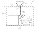
- FIG. 2 is a schematic view of a cross section taken along line AA in FIG. 1. It is sectional drawing corresponding to FIG. 2 showing schematic structure of the powder scattering property evaluation apparatus of another one Embodiment of this invention. It is sectional drawing corresponding to FIG. 2 showing schematic structure of the scattering property evaluation apparatus of the powder of another one Embodiment of this invention.
- the powder scattering property evaluation method causes the powder to be scattered as dust in the box by dropping the powder to be evaluated into a liquid placed in the box, It is characterized by measuring the dust concentration in the air in the box.
- FIG. 1 is a plan view from above schematically showing a schematic configuration of an arrangement relationship in a powder scattering property evaluation apparatus 1 according to an embodiment of the present invention.
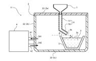
- FIG. 2 is a cross-sectional view taken along the line AA in FIG. 1, and is a schematic view showing a state in which the liquid 3 is arranged in the box 2.
- FIG. 2 shows a scattering property evaluation apparatus 1 in which a box 2 in which a liquid 3 is placed and a powder to be evaluated fall on the liquid 3 placed in the box 2 and are scattered as dust.
- a dust meter 4 for measuring the dust concentration in the air in the box 2.
- the box 2 is capable of forming a space (measurement target space) in which the powder to be evaluated is scattered as dust.
- the shape of the box body 2 is not particularly limited, but may be a shape having an upper portion 2a, a side portion 2b, and a bottom portion 2c. When viewed in plan view from the upper portion 2a or the bottom portion 2c, the shape is substantially triangular, Examples include a shape, a substantially polygonal shape, a substantially circular shape, and a substantially elliptical shape. For example, a substantially rectangular parallelepiped box 2 having an upper portion 2a, side portions 2b, and a bottom portion 2c can be suitably used.
- the volume of the box 2, that is, the volume of the space in which the powder is scattered is preferably about 10 to 300 L, and more preferably about 10 to 150 L.
- the box 2 In order to drop the powder onto the liquid 3 placed in the box 2, the box 2 enters the box 2 at a position above the liquid level 3 a of the liquid 3 placed in the box 2. It is preferable to provide a hole 21 serving as an entrance for the powder. As shown in FIGS. 1 and 2, if a hole 21 is provided in the upper part 2 a of the box 2, the hole 21 is positioned above the liquid level 3 a of the liquid 3 placed in the box 2. It is more preferable in that the powder can be easily dropped from the hole 21 to the liquid 3 placed in the box 2. Even if a hole is provided in the side portion 2b of the box body 2 at a position that is above the liquid surface 3a of the liquid 3 by using a supply path described later, the liquid 3 placed in the box body 2 is It is possible to drop the powder.
- the box 2 is preferably a substantially sealed box 2 that forms a closed space except for the holes 21.
- the diameter of the hole 21 is preferably about 10 to 100 mm.
- the box body 2 includes a box body 22 having an upper opening, and a lid body 23 that covers the upper portion of the box body 22, and the above-described hole portion 21 is provided in the lid body 23.
- the box body 22 constitutes the side part 2 b and the bottom part 2 c of the box body 2
- the lid body 23 constitutes the upper part 2 a of the box body 2.
- an opening / closing portion such as a slide type or a push-pull type may be provided on the upper portion 2a and / or the side portion 2b of the box body 2 instead of or together with the lid body 23.
- the liquid 3 and the dust meter 4 are arranged in the box 2 in the measurement preparation stage, or the liquid 3 and the dust meter 4 from the box 2 at the end of the measurement and at the time of non-measurement. Can also be taken out.
- the above-described substantially hermetically sealed box is formed by closing the opening / closing portion, which can contribute to improvement in measurement accuracy.
- the box body 2 is preferably transparent or translucent so that the inside of the box body 2 can be visually recognized from the outside of the box body 2.
- all or part of the box 2 may be transparent or translucent.
- the material of the box 2 that can visually recognize the inside from the outside include plastic and glass. From the viewpoint of manufacturing cost, mass, handleability, safety, and the like, plastic is preferable.
- the plastic include polypropylene, polyethylene, acrylic resin, and polyester resin.
- the evaluation target powder is not particularly limited. Any powder that may be scattered as dust when used in applications depending on the powder can be subject to evaluation.
- the material of the powder include flour such as wheat flour, rice flour, corn flour, and potato starch, calcium sulfate, calcium carbonate, calcium hydroxide, silicon dioxide, talc, iron oxide, aluminum, aluminum oxide, aluminum hydroxide, and oxidation.
- examples thereof include inorganic powders such as magnesium and magnesium hydroxide, and synthetic resin powders.
- a powder product in which a plurality of different or similar types of powders such as gypsum, plaster, cement, and dental powder products are mixed can be used as the evaluation target powder.
- the method and the apparatus 1 of the present embodiment are more suitable for relatively evaluating the scattering property of the powder. Therefore, the powder to be evaluated is subjected to a process for suppressing the generation of dust. More preferred are powdered products, for which so-called dust-free products are sold. Further suitable powder products include, for example, dental gypsum-based investment materials, dental phosphate-based investment materials, dental silica-based investment materials, dental hard gypsum, dental super-hard gypsum, and dental calcined gypsum. Dental powder products such as
- the amount of the powder dropped into the liquid 3 is preferably 0.05 to 0.80 g per liter of the volume of the box 2 so that an appropriate amount of powder is scattered as dust in the box 2. More preferably, it is 0.08 to 0.65 g.
- the amount of the powder dropped into the liquid 3 can be appropriately adjusted according to properties such as the density of the powder to be evaluated.
- the liquid 3 placed in the box 2 may be prepared in the box 2 at least during measurement.
- the liquid 3 is preferably replaced every time the dust concentration of the powder is measured. Therefore, the liquid 3 is preferably placed in the box 2 at the time of measurement, more preferably at every measurement. More preferably, as shown in FIG. 2, the liquid is put in a container 5 whose upper part is opened at the time of measurement, and the container 5 containing the liquid 3 is accommodated in the box 2, whereby the box 2 It is good to be placed inside. By using such a container 5, the exchange of the liquid 3 and the cleaning of the portion into which the liquid 3 is placed are facilitated.
- the scattering property evaluation apparatus 1 can further include a container 5 (hereinafter sometimes referred to as a “liquid container”) 5 into which the liquid 3 is placed. .
- a container 5 hereinafter sometimes referred to as a “liquid container”
- a mark is provided in the arrangement position of the liquid container 5 in the box 2.
- a fixing portion for fixing at a predetermined position in the box body 2 is provided.
- the end in the box 2 is preferable.
- the box 2 has a shape with corners (including rounded corners) in a plan view of the bottom 2c, such as a substantially rectangular parallelepiped box 2, as shown in FIG.
- the liquid 3 is arranged at the position of the end or corner in the box 2, and the dust meter 4 described later is arranged so as to face the position of the liquid 3, so that the dust meter 4 is removed from the liquid 3 that is a dust generation source. Taking a certain distance can contribute to improvement of measurement accuracy.
- the liquid container 5 is not particularly limited as long as the upper part is opened to such an extent that the powder to be evaluated can fall and come into sufficient contact with the liquid surface 3a of the liquid 3 placed in the container 5.
- Examples of such a container 5 include a dish shape, a bowl shape, and a cup shape. Since the liquid 3 is preferably placed in the container 5 in an amount having a certain depth so that the powder falling on the liquid 3 can be sufficiently scattered as dust, the container 5 has a bowl-shaped or A cup type is preferred.
- the amount of the liquid 3 placed in the box 2 is not particularly limited, and can be appropriately determined according to the volume of the box 2 and the amount of powder used. For example, it is preferably 50 to 2400 mL, 80 More preferably, it is set to ⁇ 1000 mL.
- the liquid 3 is contained in a liquid container 5 that is separate from the box 2. May be.
- liquid can be put into a liquid injection part formed in a dish shape, bowl shape, cup shape, etc. integrally provided in the box 2, or a liquid injection part formed of a partition plate, etc.
- the liquid 3 may be placed in the box 2.
- the size of the opening of the liquid container 5 or the liquid injection part is such that the powder to be evaluated can be sufficiently brought into contact with the liquid surface 3a of the liquid 3 and the powder is liquid. If it is a magnitude
- the size of the opening of the liquid container 5 or the liquid injection part is determined by the diameter of the hole 21 of the box 2 and the supply described later for guiding the powder from the hole 21 to the liquid 3. It is preferably larger than the width or diameter of the path.
- the type of the liquid 3 it is desirable to use a liquid that matches the actual usage of the powder to be evaluated.
- the powder to be evaluated is a dental gypsum-based investment material or a calcined gypsum for a dental model (such as dental hard gypsum, dental super-hard gypsum, and dental calcined gypsum)
- the dental gypsum-based investment material Since calcined gypsum for dental models is mixed with water and used, it is preferable to use water as the liquid 3.
- the powder to be evaluated is a phosphate-based dental investment material
- the dental investment material is used by being mixed with an aqueous solution of colloidal silica. Is preferably used.
- water is used as the liquid 3. It is preferable to use it.
- the scattering property evaluation apparatus 1 can further include a supply path 6 that guides the powder from the hole 21 to the liquid 3.
- the supply path 6 can be connected to the hole 21 provided in the box 2 described above.
- the hole 21 side in the supply path 6 can be a portion (introduction portion) 6a into which powder is introduced, and the end opposite to the introduction portion 6a is supplied with powder to the liquid 3.
- Part (supply part) 6b Part (supply part) 6b.
- the introduction portion 6a side may be provided so as to penetrate from the hole portion 21 to the outside of the box body 2.
- the supply path 6 is provided so that the powder can be scattered as dust when the powder falls on the liquid 3 placed in the box 2.
- the shape of the supply path 6 include a tubular shape, a semi-tubular shape, and a slope shape, and the cross-sectional shape thereof includes, for example, a circular shape, an elliptical shape, a square shape, a rectangular shape, an arc shape, and a U shape. And the like.
- the supply path 6 is preferably tubular (supply pipe).
- the width (diameter) of the supply path 6 (supply pipe) and the widths (diameters) of the introduction part 6a and the supply part 6b are as large as the diameter of the hole 21 provided in the box 2 described above. can do.
- the supply path 6 may be provided linearly from the hole portion 21 of the box body 2 toward the liquid 3 or may be provided in a curved shape, and the box body from the hole portion 21 toward the liquid 3. 2 may be provided in a straight line shape along the height direction. Further, the supply path 6 includes a portion (vertical portion) 61 along the height direction of the box body 2 (perpendicular direction to the liquid surface 3 a of the liquid 3), the height direction of the box body 2, and the liquid surface 3 a of the liquid 3. And a portion (inclined portion) 62 that is inclined with respect to the surface. In this case, in the supply path 6, the introduction part 6a side may be an inclined part or a vertical part, and the supply part 6b side may be an inclined part or a vertical part.
- the supply path 6 has an inclined portion where the supply portion 6 b side for supplying powder to the liquid 3 is inclined with respect to the liquid surface 3 a of the liquid 3, and the powder slides toward the liquid 3. More preferably, 62 is provided.
- the powder supplied from the supply unit 6 b continuous to the inclined unit 62 falls into the liquid 3 from the obliquely upward direction with respect to the liquid surface 3 a of the liquid 3. Since the supply path 6 includes the inclined portion 62, when the powder falls from the inclined portion 62 to the liquid 3, the powder can be actively scattered as dust.
- the inclined portion 62 is preferably configured such that at least the supply portion 6 b side is inclined with respect to the liquid surface 3 a of the liquid 3, and the entire supply path 6 is inclined with respect to the liquid surface 3 a of the liquid 3. Good.
- the angle ⁇ formed by the inclined portion 62 and the liquid surface 3a of the liquid 3 is preferably 20 to 70 °, and more preferably 30 to 60 °.
- a tubular supply path (supply pipe) 6 is illustrated.
- the connection side with the hole portion 21 of the box 2 is an introduction port (introduction portion) 6 a through which powder is introduced, and the side opposite to the introduction port 6 a is the powder 3.
- the supply pipe 6 includes a vertical portion 61 formed on the introduction port 6a side along the height direction of the box 2, and an inclined portion 62 formed continuously from the vertical portion 61 to the supply port 6b. ing.
- the supply path 6 is provided with the supply unit 6b away from the liquid surface 3a of the liquid 3 by a predetermined height so that the powder falling on the liquid 3 is more easily scattered as dust.
- the supply path 6 is provided with a supply port (supply part) 6 b separated from the liquid surface 3 a of the liquid 3 by a predetermined height h.
- the distance (height) h between the liquid surface 3a of the liquid 3 and the lower end of the supply port (supply part) 6b is preferably 1 to 30 mm, more preferably 5 to 15 mm.
- the scattering property evaluation apparatus 10 can include a hopper portion 7 connected to the hole portion 21 of the box body 2 on the box body 2.
- FIG. 3 is a schematic configuration diagram showing an example in which the hopper portion 7 is attached to the hole portion 21 of the box 2 in the apparatus shown in FIG. In the apparatus 10 shown in FIG.
- the outlet side end portion 7 a of the hopper portion 7 is inserted into the introduction port 6 a in the supply path 6 in which the introduction port 6 a side is inserted and accommodated in the hole portion 21 of the box body 2.
- the connection mode of the hopper 7, the hole 21, and the supply path 6 is not limited.
- the introduction port 6 a of the supply path 6 is provided through the hole 21 to the outside of the box 2, and at a position outside the box 2 away from the hole 21 of the box 2, The outlet side end portion 7a may be connected to the introduction port 6a.
- a dust measuring device used for measuring a general-purpose work environment can be used.
- the dust meter 4 that can be used include a light scattering dust measuring device, a light absorption dust measuring device, and a voltage balance dust measuring device.
- the light scattering type dust measuring device is preferable because it can be used easily.
- the dust meter 4 is preferably placed in the box 2 at the time of use (measurement).
- the dust concentration in the air in the box 2 when the powder is dropped into the liquid 3 placed in the box 2 and scattered as dust by the dust meter 4 arranged in the box 2 with high accuracy. Can be measured.
- the dust meter 4 is more preferably arranged at the end (corner) position in the box 2, and it is measured that the dust meter 4 is arranged so as to face the arrangement position of the liquid 3 described above. This is preferable in that the range can be expanded and the measurement accuracy can be improved.
- the dust meter 4 does not have to be placed in the box 2 during use (measurement). If the dust concentration in the air in the box can be measured, the dust meter 4 is placed outside the box 2. It may be placed. For example, as shown in FIG. 4, an intake pipe 41 for sucking the air in the box body 2 into the dust meter 4 in the scattering evaluation device 11 and an exhaust pipe for discharging the sucked air into the box body 2. 42 can be attached. Even if the dust meter 4 is placed outside the box body 2 by using the dust meter 4 including the intake pipe 41 and the exhaust pipe 42 connected to the inside of the box body 2, The dust concentration in the air in 2 can be measured.
- the box 2 is connected to the intake pipe 41 and connected to the intake hole 241 for sending the air in the box 2 to the dust meter 4 via the intake pipe 41 and the exhaust pipe 42.
- An exhaust hole 242 for sending air into the box 2 through the exhaust pipe 42 can be provided.
- the intake pipe 41 is connected to the intake port of the dust meter 4 and the intake hole 241 provided in the side portion 2 b of the box 2, and the exhaust pipe 42 is connected to the dust pipe 4. It is connected to a total of 4 exhaust ports and exhaust holes 242 provided in the side part 2 b of the box 2.
- the dust concentration measured by the dust meter 4 can be used for evaluation of powder scattering properties. If the dust concentration is a high value, it can be evaluated that the powder is likely to be scattered, and if the dust concentration is a low value, it can be evaluated that the powder is difficult to be scattered.
- the dust concentration it is preferable to measure at least one of the number concentration [pieces / m 3 ] and the mass concentration [mg / m 3 ] of the dust.
- it is preferable to measure at least one of the maximum value and integrated value of the dust concentration and it is more preferable to measure both.
- the maximum value and integrated value of the dust concentration can be obtained by measuring the dust concentration at intervals of a predetermined time (for example, 1 minute) and acquiring a plurality of (for example, five points) measurement values.
- a step of placing the liquid 3 (more preferably, the container 5 containing the liquid 3) in the box 2 and a measurement by the dust meter 4 are started.
- the method includes a step and a step of dropping the evaluation target powder into the liquid 3.
- a step of installing the dust meter 4 in the box body 2 or outside the box body 2 may be included. It is more preferable that the measurement of the dust meter 4 is started before the powder is dropped onto the liquid 3 and the powder is dropped onto the liquid 3 after the first measurement value is obtained as a blank.
- the measurement is preferably terminated when the amount of dust decreases to the same level as the first measurement value (blank), and a predetermined time interval (for example, an interval of 10 to 120 seconds) from the start of measurement to the end of measurement. It is preferable to measure the dust concentration with
- the powder scattering property evaluation method of one embodiment of the present invention can also take the following configuration.
- [1] The powder to be evaluated is dropped into the liquid placed in the box, so that the powder is scattered as dust in the box, and the dust concentration in the box is measured with a dust meter.
- a method for evaluating powder scattering [2] The box according to [1], wherein the box includes a hole serving as an entrance of the powder into the box at a position above the liquid level of the liquid placed in the box. Powder scattering evaluation method.
- Powder scattering evaluation method [4] The powder scattering property evaluation method according to [2] or [3], wherein the powder is dropped into the liquid using a supply path that guides the powder from the hole to the liquid. [5] The supply path includes an inclined portion in which a supply portion side that supplies the powder to the liquid is inclined with respect to the liquid surface of the liquid, and the powder slides toward the liquid. The powder scattering property evaluation method according to [4]. [6] The powder scattering property evaluation method according to [5], wherein the supply path is provided with the supply unit spaced apart from the liquid surface by a predetermined height. [7] The liquid is placed in a container having an open top, and the container containing the liquid is accommodated in the box, whereby the liquid is placed in the box. ] The powder scattering property evaluation method according to any one of the above. [8] The powder scattering property evaluation method according to any one of [1] to [7], wherein the powder is a dental powder product.
- the powder scattering property evaluation apparatus may have the following configuration.
- a dust scattering evaluation apparatus comprising: a dust meter.
- the box includes a hole serving as an entrance of the powder into the box at a position above the liquid level of the liquid placed in the box.
- Powder scattering evaluation device [11] The box according to [10], wherein the box includes a box body having an upper opening, and a lid that covers the upper part of the box body, and the hole is provided in the lid. Powder scattering evaluation device.
- the powder scattering property evaluation apparatus according to [10] or [11], further including a supply path that guides the powder from the hole to the liquid.
- the supply path includes an inclined portion in which a supply portion that supplies the powder to the liquid is inclined with respect to the liquid surface of the liquid, and the powder slides toward the liquid.
- the powder scattering property evaluation apparatus according to [12].
- the powder scattering property evaluation apparatus according to any one of [9] to [14], further including a container that is accommodated in the box and in which the liquid is placed and that has an open top.
- the powder scattering property evaluation apparatus according to any one of [9] to [15], wherein the powder is a dental powder product.
- a polypropylene storage case (trade name “ST BOX 25” manufactured by Astage Co., Ltd.) having a box body and a lid, having a width of 360 mm, a height of 240 mm, and a depth of 240 mm (capacity of about 20 L) was used as the box.
- a circular hole having a diameter of 30 mm was provided at the right-side portion in the width direction and at the substantially central portion in the depth direction (see FIG. 1).
- a container with an open top is placed on one corner of the box, and a laser light scattering dust meter (trade name “Dust Monitor Dust” manufactured by SATOTECH) is placed on the corner opposite to the corner where the container is placed.
- a total of DC 170 ") (see FIG. 1).
- the center-to-center distance in plan view between the container and the dust meter was about 200 mm.
- a supply pipe for guiding the powder from the hole of the box into the container disposed in the box was used.
- a powder inlet of a supply pipe (tube diameter: 30 mm, vertical part length: 60 mm, inclined part length: 95 mm, angle ⁇ : 35 °) into the hole of the box, The hole and the supply pipe were connected (see FIGS. 2 and 3).
- Example 1 In Example 1, a dental gypsum-based investment material (trade name “Sakura Quick 20” manufactured by Yoshino Gypsum Co., Ltd.) was used as a powder to be evaluated. Since this powder is used by being mixed with water, 150 mL of water was previously placed in a container disposed in the box. At this time, the distance h between the liquid level in the container and the lower end of the supply port of the supply pipe was 5 mm. Before dropping the powder into water, measurement of the dust concentration with a dust meter was started. The measurement interval of the dust concentration was set to 1 minute, and after the first measurement was completed, 10 seconds later, 5 g of the powder was put into the container through the supply pipe from the hopper (see FIG. 3) attached to the hole of the box. Dropped into water and scattered as dust. Up to five measured values of the dust concentration in the air in the box (number concentration of particles having a particle size of 0.5 ⁇ m or more) were obtained.
- Example 2 In Example 2, instead of the powder used in Example 1, a nonionic surfactant was added to the powder used in Example 1 as a process for suppressing the generation of dust (dust-free process) The dust concentration was measured in the same manner as in Example 1 except that the dental plaster-based investment material was used.
- Comparative Example 1 In Comparative Example 1, the dust concentration was measured by the same method as in Example 1 except that water was not put into the container disposed in the box.
- Comparative Example 2 In Comparative Example 2, the dust concentration was measured in the same manner as in Example 2 except that water was not put into the container disposed in the box.
- Example 3 was the same as Example 1 except that white cement (trade name “White Cement” manufactured by Taiheiyo Cement Co., Ltd.) was used as the evaluation target powder instead of the powder used in Example 1. The dust concentration was measured by this method.
- white cement trade name “White Cement” manufactured by Taiheiyo Cement Co., Ltd.
- Example 4 In Example 4, instead of the powder used in Example 3, a nonionic surfactant was added to the powder used in Example 3 as a process for suppressing the generation of dust (dust-free process) Dust concentration was measured in the same manner as in Example 3 except that the white cement was used.
- Comparative Example 3 In Comparative Example 3, the dust concentration was measured in the same manner as in Example 3 except that water was not put into the container disposed in the box.
- Comparative Example 4 In Comparative Example 4, the dust concentration was measured in the same manner as in Example 4 except that water was not put into the container disposed in the box.
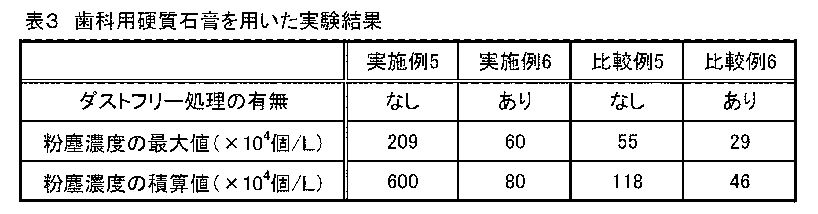
- Example 5 In Example 5, instead of the powder used in Example 1, dental hard gypsum (trade name “New High Stone Yellow” manufactured by Yoshino Gypsum Co., Ltd.) was used as the evaluation target powder. The dust concentration was measured in the same manner as in Example 1 except that the amount of powder dropped in Example 1 was changed from “5 g” to “10 g”.
- Example 6 In Example 6, in place of the powder used in Example 5, a nonionic surfactant was added to the powder used in Example 5 as a process for suppressing the generation of dust (dust-free process). The dust concentration was measured in the same manner as in Example 5 except that (hard dental plaster) was used.
- Comparative Example 5 Comparative Example 5
- the dust concentration was measured in the same manner as in Example 5 except that water was not put into the container placed in the box.
- Comparative Example 6 In Comparative Example 6, the dust concentration was measured in the same manner as in Example 6 except that water was not put into the container placed in the box.
- the powder scattering property evaluation method or the scattering property evaluation apparatus can more clearly evaluate the powder scattering property, the powder product is used, manufactured, and sold. In particular, it is useful in the sale of powder products in which the generation amount of dust is suppressed.
Landscapes
- Chemical & Material Sciences (AREA)
- Health & Medical Sciences (AREA)
- Life Sciences & Earth Sciences (AREA)
- Immunology (AREA)
- Analytical Chemistry (AREA)
- Biochemistry (AREA)
- General Health & Medical Sciences (AREA)
- General Physics & Mathematics (AREA)
- Physics & Mathematics (AREA)
- Pathology (AREA)
- Dispersion Chemistry (AREA)
- Engineering & Computer Science (AREA)
- Food Science & Technology (AREA)
- Medicinal Chemistry (AREA)
- Sampling And Sample Adjustment (AREA)
- Analysing Materials By The Use Of Radiation (AREA)
- Investigating Or Analysing Materials By Optical Means (AREA)
Abstract
Description
[1]箱体内に置かれた液体に評価対象の粉体を落下させることによって、前記箱体内にて前記粉体を粉塵として飛散させ、粉塵計で前記箱体内の空気中の粉塵濃度を測定する、粉体の飛散性評価方法。
[2]前記箱体は、前記箱体内に置かれる前記液体の液面よりも上方となる位置に、前記箱体内への前記粉体の入り口となる孔部を備える前記[1]に記載の粉体の飛散性評価方法。
[3]前記箱体は、上部が開口した箱本体と、前記箱本体の前記上部を覆う蓋体と、を備え、前記蓋体に前記孔部が設けられている前記[2]に記載の粉体の飛散性評価方法。
[4]前記粉体を前記孔部から前記液体へと導く供給路を用いて、前記液体に前記粉体を落下させる前記[2]又は[3]に記載の粉体の飛散性評価方法。
[5]前記供給路は、前記液体へ前記粉体を供給する供給部側が前記液体の前記液面に対して傾斜しており、前記粉体を前記液体に向かって滑り落とす傾斜部を備える前記[4]に記載の粉体の飛散性評価方法。
[6]前記供給路は、前記液体の前記液面から前記供給部が所定の高さ離れて設けられる前記[5]に記載の粉体の飛散性評価方法。
[7]前記液体は、上部が開口した容器に入れられ、前記液体が入った前記容器が前記箱体内に収容されることで、前記箱体内に前記液体が置かれる前記[1]~[6]のいずれかに記載の粉体の飛散性評価方法。
[8]前記粉体が歯科用粉末製品である前記[1]~[7]のいずれかに記載の粉体の飛散性評価方法。
[9]内部に液体が置かれる箱体と、評価対象の粉体が前記箱体内に置かれた液体に落下して粉塵として飛散した際に、前記箱体内の空気中の粉塵濃度を測定する粉塵計と、を備える、粉体の飛散性評価装置。
[10]前記箱体は、前記箱体内に置かれる前記液体の液面よりも上方となる位置に、前記箱体内への前記粉体の入り口となる孔部を備える前記[9]に記載の粉体の飛散性評価装置。
[11]前記箱体は、上部が開口した箱本体と、前記箱本体の前記上部を覆う蓋体と、を備え、前記蓋体に前記孔部が設けられている前記[10]に記載の粉体の飛散性評価装置。
[12]前記粉体を前記孔部から前記液体へと導く供給路をさらに備える前記[10]又は[11]に記載の粉体の飛散性評価装置。
[13]前記供給路は、前記液体へ前記粉体を供給する供給部側が前記液体の前記液面に対して傾斜しており、前記粉体を前記液体に向かって滑り落とす傾斜部を備える前記[12]に記載の粉体の飛散性評価装置。
[14]前記供給路は、前記液体の前記液面から前記供給部が所定の高さ離れて設けられている前記[13]に記載の粉体の飛散性評価装置。
[15]前記箱体内に収容されると共に、前記液体が入れられる、上部が開口した容器をさらに備える前記[9]~[14]のいずれかに記載の粉体の飛散性評価装置。
[16]前記粉体が歯科用粉末製品である前記[9]~[15]のいずれかに記載の粉体の飛散性評価装置。
箱本体と蓋体とを備え、幅360mm、高さ240mm、奥行き240mm(容量約20L)のポリプロピレン製収納ケース(アステージ社製の商品名「ST BOX 25」)を箱体として使用した。この箱体における蓋体において、幅方向における右側部分で奥行き方向における略中央部分に直径30mmの円形状の孔部を設けた(図1参照)。この箱体内の1つの隅側に上部が開口した容器を配置し、この容器を配置した隅とは対角の隅側にレーザー光散乱方式の粉塵計(SATOTECH社製の商品名「ダストモニター粉じん計DC170」)を配置した(図1参照)。容器と粉塵計との平面視における中心間距離は約200mmであった。粉体の落下には、粉体を箱体の孔部から箱体内に配置した容器内へと導く供給管を用いた。箱体内において、箱体の孔部内に供給管(管の直径:30mm、鉛直部の長さ:60mm、傾斜部の長さ:95mm、角度θ:35°)の粉体導入口を挿入し、孔部と供給管とを接続した(図2及び図3参照)。
実施例1では、評価対象の粉体として、歯科用石膏系埋没材(吉野石膏社製の商品名「サクラクイック20」)を用いた。この粉体は水と混合されて用いられるものであるため、箱体内に配置された容器には、予め水を150mL入れておいた。このとき、容器内の液体の液面と供給管の供給口の下端との距離hは5mmであった。粉体を水に落下させる前に、粉塵計による粉塵濃度の測定を開始した。粉塵濃度の測定間隔を1分間とし、1点目の測定が完了した後、10秒後に、粉体5gを箱体の孔部に取り付けたホッパー部(図3参照)から供給管を通じて容器内の水に落下させ、粉塵として飛散させた。この際の箱体内の空気中の粉塵濃度(粒径0.5μm以上の粒子の個数濃度)の測定値を5点まで取得した。
実施例2では、実施例1で使用した粉体の代わりに、実施例1で使用した粉体に、粉塵の発生を抑制する処理として、非イオン系界面活性剤を添加したもの(ダストフリー処理の歯科用石膏系埋没材)を用いた以外は、実施例1と同様の方法で粉塵濃度の測定を行った。
比較例1では、箱体内に配置した容器に水を入れなかった以外は、実施例1と同様の方法で粉塵濃度の測定を行った。
比較例2では、箱体内に配置した容器に水を入れなかった以外は、実施例2と同様の方法で粉塵濃度の測定を行った。
実施例3では、実施例1で使用した粉体の代わりに、評価対象の粉体として、白色セメント(太平洋セメント社製の商品名「ホワイトセメント」)を用いた以外は、実施例1と同様の方法で粉塵濃度の測定を行った。
実施例4では、実施例3で使用した粉体の代わりに、実施例3で使用した粉体に、粉塵の発生を抑制する処理として、非イオン系界面活性剤を添加したもの(ダストフリー処理の白色セメント)を用いた以外は、実施例3と同様の方法で粉塵濃度の測定を行った。
比較例3では、箱体内に配置した容器に水を入れなかった以外は、実施例3と同様の方法で粉塵濃度の測定を行った。
比較例4では、箱体内に配置した容器に水を入れなかった以外は、実施例4と同様の方法で粉塵濃度の測定を行った。
実施例5では、実施例1で使用した粉体の代わりに、評価対象の粉体として、歯科用硬質石膏(吉野石膏社製の商品名「ニューハイストーンイエロー」)を用いたこと、及び実施例1で落下させた粉体の量「5g」を「10g」に変更したこと以外は、実施例1と同様の方法で粉塵濃度の測定を行った。
実施例6では、実施例5で使用した粉体の代わりに、実施例5で使用した粉体に、粉塵の発生を抑制する処理として、非イオン系界面活性剤を添加したもの(ダストフリー処理の歯科用硬質石膏)を用いた以外は、実施例5と同様の方法で粉塵濃度の測定を行った。
比較例5では、箱体内に配置した容器に水を入れなかった以外は、実施例5と同様の方法で粉塵濃度の測定を行った。
比較例6では、箱体内に配置した容器に水を入れなかった以外は、実施例6と同様の方法で粉塵濃度の測定を行った。


2 箱体
3 液体
4 粉塵計
5 容器
6 供給路
Claims (16)
- 箱体内に置かれた液体に評価対象の粉体を落下させることによって、前記箱体内にて前記粉体を粉塵として飛散させ、粉塵計で前記箱体内の空気中の粉塵濃度を測定する、粉体の飛散性評価方法。
- 前記箱体は、前記箱体内に置かれる前記液体の液面よりも上方となる位置に、前記箱体内への前記粉体の入り口となる孔部を備える請求項1に記載の粉体の飛散性評価方法。
- 前記箱体は、上部が開口した箱本体と、前記箱本体の前記上部を覆う蓋体と、を備え、前記蓋体に前記孔部が設けられている請求項2に記載の粉体の飛散性評価方法。
- 前記粉体を前記孔部から前記液体へと導く供給路を用いて、前記液体に前記粉体を落下させる請求項2又は3に記載の粉体の飛散性評価方法。
- 前記供給路は、前記液体へ前記粉体を供給する供給部側が前記液体の前記液面に対して傾斜しており、前記粉体を前記液体に向かって滑り落とす傾斜部を備える請求項4に記載の粉体の飛散性評価方法。
- 前記供給路は、前記液体の前記液面から前記供給部が所定の高さ離れて設けられる請求項5に記載の粉体の飛散性評価方法。
- 前記液体は、上部が開口した容器に入れられ、前記液体が入った前記容器が前記箱体内に収容されることで、前記箱体内に前記液体が置かれる請求項1~6のいずれか1項に記載の粉体の飛散性評価方法。
- 前記粉体が歯科用粉末製品である請求項1~7のいずれか1項に記載の粉体の飛散性評価方法。
- 内部に液体が置かれる箱体と、
評価対象の粉体が前記箱体内に置かれた液体に落下して粉塵として飛散した際に、前記箱体内の空気中の粉塵濃度を測定する粉塵計と、
を備える、粉体の飛散性評価装置。 - 前記箱体は、前記箱体内に置かれる前記液体の液面よりも上方となる位置に、前記箱体内への前記粉体の入り口となる孔部を備える請求項9に記載の粉体の飛散性評価装置。
- 前記箱体は、上部が開口した箱本体と、前記箱本体の前記上部を覆う蓋体と、を備え、前記蓋体に前記孔部が設けられている請求項10に記載の粉体の飛散性評価装置。
- 前記粉体を前記孔部から前記液体へと導く供給路をさらに備える請求項10又は11に記載の粉体の飛散性評価装置。
- 前記供給路は、前記液体へ前記粉体を供給する供給部側が前記液体の前記液面に対して傾斜しており、前記粉体を前記液体に向かって滑り落とす傾斜部を備える請求項12に記載の粉体の飛散性評価装置。
- 前記供給路は、前記液体の前記液面から前記供給部が所定の高さ離れて設けられている請求項13に記載の粉体の飛散性評価装置。
- 前記箱体内に収容されると共に、前記液体が入れられる、上部が開口した容器をさらに備える請求項9~14のいずれか1項に記載の粉体の飛散性評価装置。
- 前記粉体が歯科用粉末製品である請求項9~15のいずれか1項に記載の粉体の飛散性評価装置。
Priority Applications (14)
| Application Number | Priority Date | Filing Date | Title |
|---|---|---|---|
| MYPI2018703053A MY195265A (en) | 2016-05-02 | 2017-04-14 | Powder Dustiness Evaluation Method and Powder Dustiness Evaluation Device |
| RU2018135212A RU2699309C1 (ru) | 2016-05-02 | 2017-04-14 | Способ и аппарат для оценивания рассеивающих свойств порошка |
| CA3022676A CA3022676C (en) | 2016-05-02 | 2017-04-14 | Powder dustiness evaluation method and powder dustiness evaluation device |
| SG11201807595PA SG11201807595PA (en) | 2016-05-02 | 2017-04-14 | Powder dustiness evaluation method and powder dustiness evaluation device |
| US16/082,620 US10684222B2 (en) | 2016-05-02 | 2017-04-14 | Powder dustiness evaluation method and powder dustiness evaluation device |
| MX2018012092A MX392769B (es) | 2016-05-02 | 2017-04-14 | Metodo para evaluar la dispersion de un polvo y dispositivo para evaluar la dispersion de un polvo. |
| EP17792678.9A EP3454040A4 (en) | 2016-05-02 | 2017-04-14 | POWDER DUST CONTENT ASSESSMENT METHOD AND POWDER DUST CONTENT ASSESSMENT DEVICE |
| JP2018515415A JP6779284B2 (ja) | 2016-05-02 | 2017-04-14 | 粉体の飛散性評価方法及び粉体の飛散性評価装置 |
| AU2017260929A AU2017260929B2 (en) | 2016-05-02 | 2017-04-14 | Powder dustiness evaluation method and powder dustiness evaluation device |
| CN201780023256.6A CN109073522B (zh) | 2016-05-02 | 2017-04-14 | 粉末的飞散性评价方法和粉末的飞散性评价装置 |
| HK19101059.5A HK1258759B (en) | 2016-05-02 | 2017-04-14 | Powder dustiness evaluation method and powder dustiness evaluation device |
| BR112018070433-4A BR112018070433B1 (pt) | 2016-05-02 | 2017-04-14 | Método e aparelho para avaliar uma propriedade de dispersão de um pó |
| KR1020187034399A KR102165372B1 (ko) | 2016-05-02 | 2017-04-14 | 분체의 비산성 평가 방법 및 분체의 비산성 평가 장치 |
| PH12018502284A PH12018502284A1 (en) | 2016-05-02 | 2018-10-26 | Powder dustiness evaluation method and powder dustiness evaluation device |
Applications Claiming Priority (2)
| Application Number | Priority Date | Filing Date | Title |
|---|---|---|---|
| JP2016-092290 | 2016-05-02 | ||
| JP2016092290 | 2016-05-02 |
Publications (1)
| Publication Number | Publication Date |
|---|---|
| WO2017191745A1 true WO2017191745A1 (ja) | 2017-11-09 |
Family
ID=60202904
Family Applications (1)
| Application Number | Title | Priority Date | Filing Date |
|---|---|---|---|
| PCT/JP2017/015308 Ceased WO2017191745A1 (ja) | 2016-05-02 | 2017-04-14 | 粉体の飛散性評価方法及び粉体の飛散性評価装置 |
Country Status (15)
| Country | Link |
|---|---|
| US (1) | US10684222B2 (ja) |
| EP (1) | EP3454040A4 (ja) |
| JP (1) | JP6779284B2 (ja) |
| KR (1) | KR102165372B1 (ja) |
| CN (1) | CN109073522B (ja) |
| AU (1) | AU2017260929B2 (ja) |
| BR (1) | BR112018070433B1 (ja) |
| CA (1) | CA3022676C (ja) |
| MX (1) | MX392769B (ja) |
| MY (1) | MY195265A (ja) |
| PH (1) | PH12018502284A1 (ja) |
| RU (1) | RU2699309C1 (ja) |
| SG (1) | SG11201807595PA (ja) |
| TW (1) | TWI746541B (ja) |
| WO (1) | WO2017191745A1 (ja) |
Families Citing this family (3)
| Publication number | Priority date | Publication date | Assignee | Title |
|---|---|---|---|---|
| CN110678731B (zh) * | 2017-05-25 | 2022-09-16 | 信越化学工业株式会社 | 粉体的疏水化度的解析方法、高疏水化度处理着色颜料以及含有其的化妆料 |
| KR102312875B1 (ko) * | 2021-05-27 | 2021-10-14 | 주식회사 그린켐텍 | 습윤식 비산방지제 성능평가장치 |
| US11840408B1 (en) | 2022-12-08 | 2023-12-12 | PetSmart Home Office, Inc. | Apparatuses and methods for measuring dustiness of a product |
Citations (3)
| Publication number | Priority date | Publication date | Assignee | Title |
|---|---|---|---|---|
| JPS62212255A (ja) * | 1986-03-12 | 1987-09-18 | 而至歯科工業株式会社 | 低粉塵性粉末状歯科用石こう組成物 |
| JPH0283022A (ja) * | 1988-09-21 | 1990-03-23 | Kunimine Kogyo Kk | スラリー調製装置 |
| JPH0290984A (ja) * | 1988-09-26 | 1990-03-30 | Benkan Corp | 水中溶存酸素の除去方法 |
Family Cites Families (30)
| Publication number | Priority date | Publication date | Assignee | Title |
|---|---|---|---|---|
| AT393169B (de) * | 1985-06-05 | 1991-08-26 | Staudinger Gernot | Verfahren und vorrichtung zur korngroessenanalyse |
| JPS63119887A (ja) * | 1986-11-06 | 1988-05-24 | カネボウ株式会社 | 選別装置 |
| JPH0748065B2 (ja) * | 1988-05-27 | 1995-05-24 | 信越化学工業株式会社 | 白色系粉体中の着色異物検査方法および装置 |
| GB9012417D0 (en) * | 1990-06-04 | 1990-07-25 | Sortex Ltd | Method and apparatus for sorting material |
| RU2045757C1 (ru) * | 1992-08-05 | 1995-10-10 | Астахов Александр Валентинович | Способ фотоседиментационного анализа дисперсности порошковых материалов однородного вещественного состава |
| US5561515A (en) * | 1994-10-07 | 1996-10-01 | Tsi Incorporated | Apparatus for measuring particle sizes and velocities |
| US5701012A (en) * | 1996-03-19 | 1997-12-23 | Her Majesty The Queen In Right Of Canada, As Represented By The Minister Of National Defence | Fluorescent biological particle detection system |
| US5818577A (en) * | 1996-12-30 | 1998-10-06 | General Electric Company | Detection method and apparatus for contamination in quartz sand |
| JP2000237572A (ja) * | 1999-02-19 | 2000-09-05 | Akebono Brake Res & Dev Center Ltd | 造粒方法 |
| US6352585B1 (en) * | 1999-04-12 | 2002-03-05 | Michael Diesso | Gypsum casting composition and method of casting |
| JP3862153B2 (ja) * | 2000-01-27 | 2006-12-27 | 協和醗酵工業株式会社 | 定量吐出装置及び粉体材料の吐出方法 |
| JP2004219392A (ja) * | 2003-01-10 | 2004-08-05 | Kaya Frock Kk | 発塵性評価装置 |
| CN1791533B (zh) * | 2003-03-20 | 2012-07-11 | 株式会社理光 | 粉体充填装置和方法、及回转状辅助容器 |
| AU2003903703A0 (en) * | 2003-07-18 | 2003-07-31 | Garrett Thermal Systems Limited | Method and system for a filter |
| JP4139788B2 (ja) * | 2004-02-25 | 2008-08-27 | 株式会社粉研パウテックス | 粉体/液体連続混合造粒方法および装置 |
| NO326482B1 (no) * | 2005-05-31 | 2008-12-15 | Integrated Optoelectronics As | En ny infrarod laserbasert alarm |
| JP4792611B2 (ja) * | 2006-02-01 | 2011-10-12 | リオン株式会社 | 粒子計測装置 |
| EP1862795A1 (en) * | 2006-05-10 | 2007-12-05 | ABB Schweiz AG | Bulk Material Analyzer System |
| JP5508852B2 (ja) * | 2007-08-30 | 2014-06-04 | 日本碍子株式会社 | 被検体の欠陥検査方法 |
| WO2010141353A1 (en) * | 2009-06-02 | 2010-12-09 | First Solar, Inc. | Powder feed rate sensor |
| JP5691163B2 (ja) * | 2009-12-01 | 2015-04-01 | セントラル硝子株式会社 | クリーニングガス |
| US8274038B2 (en) * | 2009-12-14 | 2012-09-25 | Akj Industries, Inc. | Dust control and flow control testing device and method of reducing airborne dust and increasing flow of bulk materials |
| EP2717035B1 (de) * | 2012-10-02 | 2016-12-07 | Palas GmbH Partikel-und Lasermesstechnik | Verfahren und Vorrichtung zum Untersuchen kleiner Partikel in Gas |
| US9448155B2 (en) * | 2014-06-25 | 2016-09-20 | The United States Of America As Represented By The Secretary Of The Army | System for sampling and/or analysis of particles in a gaseous environment |
| KR20160030662A (ko) * | 2014-09-11 | 2016-03-21 | 한국기계연구원 | 날림 모래 및 먼지 시험 장비 |
| TWM504953U (zh) * | 2015-01-19 | 2015-07-11 | Nat Univ Tsing Hua | 可攜式多波段光度計 |
| JP6525716B2 (ja) * | 2015-05-08 | 2019-06-05 | キヤノン株式会社 | トナー |
| CN105181902A (zh) * | 2015-09-30 | 2015-12-23 | 华电电力科学研究院 | 一种基于液体吸收法的在线氨逃逸浓度测量装置及测量方法 |
| CN205080028U (zh) * | 2015-10-22 | 2016-03-09 | 比亚迪股份有限公司 | 一种悬浮颗粒物检测装置 |
| CN105547930A (zh) * | 2015-12-04 | 2016-05-04 | 上海同化新材料科技有限公司 | 粉体材料扬尘的检测装置及其检测方法 |
-
2017
- 2017-04-14 JP JP2018515415A patent/JP6779284B2/ja active Active
- 2017-04-14 CA CA3022676A patent/CA3022676C/en active Active
- 2017-04-14 CN CN201780023256.6A patent/CN109073522B/zh not_active Expired - Fee Related
- 2017-04-14 AU AU2017260929A patent/AU2017260929B2/en not_active Ceased
- 2017-04-14 BR BR112018070433-4A patent/BR112018070433B1/pt not_active IP Right Cessation
- 2017-04-14 SG SG11201807595PA patent/SG11201807595PA/en unknown
- 2017-04-14 EP EP17792678.9A patent/EP3454040A4/en not_active Withdrawn
- 2017-04-14 US US16/082,620 patent/US10684222B2/en active Active
- 2017-04-14 KR KR1020187034399A patent/KR102165372B1/ko not_active Expired - Fee Related
- 2017-04-14 WO PCT/JP2017/015308 patent/WO2017191745A1/ja not_active Ceased
- 2017-04-14 MY MYPI2018703053A patent/MY195265A/en unknown
- 2017-04-14 MX MX2018012092A patent/MX392769B/es unknown
- 2017-04-14 RU RU2018135212A patent/RU2699309C1/ru active
- 2017-04-17 TW TW106112764A patent/TWI746541B/zh not_active IP Right Cessation
-
2018
- 2018-10-26 PH PH12018502284A patent/PH12018502284A1/en unknown
Patent Citations (3)
| Publication number | Priority date | Publication date | Assignee | Title |
|---|---|---|---|---|
| JPS62212255A (ja) * | 1986-03-12 | 1987-09-18 | 而至歯科工業株式会社 | 低粉塵性粉末状歯科用石こう組成物 |
| JPH0283022A (ja) * | 1988-09-21 | 1990-03-23 | Kunimine Kogyo Kk | スラリー調製装置 |
| JPH0290984A (ja) * | 1988-09-26 | 1990-03-30 | Benkan Corp | 水中溶存酸素の除去方法 |
Also Published As
| Publication number | Publication date |
|---|---|
| CA3022676A1 (en) | 2017-11-09 |
| TWI746541B (zh) | 2021-11-21 |
| AU2017260929A1 (en) | 2018-09-13 |
| RU2699309C1 (ru) | 2019-09-04 |
| BR112018070433B1 (pt) | 2023-01-10 |
| CA3022676C (en) | 2022-01-18 |
| BR112018070433A2 (pt) | 2019-02-05 |
| TW201807397A (zh) | 2018-03-01 |
| KR102165372B1 (ko) | 2020-10-14 |
| MX392769B (es) | 2025-03-24 |
| KR20190002604A (ko) | 2019-01-08 |
| JPWO2017191745A1 (ja) | 2019-03-07 |
| JP6779284B2 (ja) | 2020-11-04 |
| AU2017260929B2 (en) | 2019-09-26 |
| HK1258759A1 (zh) | 2019-11-22 |
| CN109073522A (zh) | 2018-12-21 |
| SG11201807595PA (en) | 2018-11-29 |
| MY195265A (en) | 2023-01-11 |
| PH12018502284A1 (en) | 2019-07-15 |
| CN109073522B (zh) | 2021-06-25 |
| US20190025206A1 (en) | 2019-01-24 |
| EP3454040A1 (en) | 2019-03-13 |
| EP3454040A4 (en) | 2020-01-01 |
| MX2018012092A (es) | 2019-01-14 |
| US10684222B2 (en) | 2020-06-16 |
Similar Documents
| Publication | Publication Date | Title |
|---|---|---|
| WO2017191745A1 (ja) | 粉体の飛散性評価方法及び粉体の飛散性評価装置 | |
| US20170267386A1 (en) | Dosing and cleaning sample preparation apparatus and methods thereof | |
| TW201629453A (zh) | 飛灰自動取樣裝置以及飛灰自動取樣方法 | |
| JP2025027051A (ja) | 医薬品を調製するための方法 | |
| CA2775644C (en) | A measuring device | |
| HK1258759B (en) | Powder dustiness evaluation method and powder dustiness evaluation device | |
| ATE402401T1 (de) | Vorrichtung zur messung des massedurchflusses eines partikelförmigen materials | |
| Serrano et al. | The Hagen-Beverloo law for outflow of granular solids from holes on side walls | |
| JP3962181B2 (ja) | 粒径分布測定装置と粒径分布測定に用いる試料供給装置 | |
| Yu et al. | Retention modeling of refractory ceramic fibers (RCF) in humans | |
| JP2014015298A (ja) | 粉体定量供給装置 | |
| JP2011140325A (ja) | 計量繰出し容器 | |
| JP2004325398A (ja) | 連続吸入用ニードル及び連続吸入装置 | |
| Hou | Development of a micro-feeder for cohesive pharmaceutical powders | |
| CN223433372U (zh) | 玻璃窑炉斗提机的检查口结构和玻璃窑炉斗提机 | |
| JP2011080779A (ja) | 計量スプーン | |
| EP1977737A1 (en) | Flow assessment apparatus and method for quantitatively assessing the flow properties of particulate material | |
| JP2008094617A (ja) | パーツフィーダ | |
| CN205280414U (zh) | 一种钛合金熔铸用混合料取样装置 | |
| JP2010230642A (ja) | メジャーカップ | |
| JP2011147743A (ja) | 粉薬剤調節器具付き蓋 | |
| ITRM20100210A1 (it) | Dispositivo e procedimento per il trasporto pneumatico di prodotti in polvere. | |
| JP2005156222A (ja) | ダスト分散装置 | |
| TH1801003772A (th) | กรรมวิธีการผลิตวัสดุฉาบฐานฟันเทียมแบบนุ่มชนิดอะคริลิก | |
| IES20100397A2 (en) | A measuring device |
Legal Events
| Date | Code | Title | Description |
|---|---|---|---|
| ENP | Entry into the national phase |
Ref document number: 2018515415 Country of ref document: JP Kind code of ref document: A |
|
| ENP | Entry into the national phase |
Ref document number: 2017260929 Country of ref document: AU Date of ref document: 20170414 Kind code of ref document: A |
|
| REG | Reference to national code |
Ref country code: BR Ref legal event code: B01A Ref document number: 112018070433 Country of ref document: BR |
|
| ENP | Entry into the national phase |
Ref document number: 3022676 Country of ref document: CA |
|
| NENP | Non-entry into the national phase |
Ref country code: DE |
|
| ENP | Entry into the national phase |
Ref document number: 20187034399 Country of ref document: KR Kind code of ref document: A |
|
| 121 | Ep: the epo has been informed by wipo that ep was designated in this application |
Ref document number: 17792678 Country of ref document: EP Kind code of ref document: A1 |
|
| ENP | Entry into the national phase |
Ref document number: 2017792678 Country of ref document: EP Effective date: 20181203 |
|
| ENP | Entry into the national phase |
Ref document number: 112018070433 Country of ref document: BR Kind code of ref document: A2 Effective date: 20181004 |