WO2017191753A1 - ホッパーおよび錠剤印刷装置 - Google Patents
ホッパーおよび錠剤印刷装置 Download PDFInfo
- Publication number
- WO2017191753A1 WO2017191753A1 PCT/JP2017/015623 JP2017015623W WO2017191753A1 WO 2017191753 A1 WO2017191753 A1 WO 2017191753A1 JP 2017015623 W JP2017015623 W JP 2017015623W WO 2017191753 A1 WO2017191753 A1 WO 2017191753A1
- Authority
- WO
- WIPO (PCT)
- Prior art keywords
- hopper
- tablet
- edible body
- unit
- edible
- Prior art date
- Legal status (The legal status is an assumption and is not a legal conclusion. Google has not performed a legal analysis and makes no representation as to the accuracy of the status listed.)
- Ceased
Links
Images



Classifications
-
- A—HUMAN NECESSITIES
- A61—MEDICAL OR VETERINARY SCIENCE; HYGIENE
- A61J—CONTAINERS SPECIALLY ADAPTED FOR MEDICAL OR PHARMACEUTICAL PURPOSES; DEVICES OR METHODS SPECIALLY ADAPTED FOR BRINGING PHARMACEUTICAL PRODUCTS INTO PARTICULAR PHYSICAL OR ADMINISTERING FORMS; DEVICES FOR ADMINISTERING FOOD OR MEDICINES ORALLY; BABY COMFORTERS; DEVICES FOR RECEIVING SPITTLE
- A61J3/00—Devices or methods specially adapted for bringing pharmaceutical products into particular physical or administering forms
- A61J3/06—Devices or methods specially adapted for bringing pharmaceutical products into particular physical or administering forms into the form of pills, lozenges or dragees
-
- B—PERFORMING OPERATIONS; TRANSPORTING
- B65—CONVEYING; PACKING; STORING; HANDLING THIN OR FILAMENTARY MATERIAL
- B65G—TRANSPORT OR STORAGE DEVICES, e.g. CONVEYORS FOR LOADING OR TIPPING, SHOP CONVEYOR SYSTEMS OR PNEUMATIC TUBE CONVEYORS
- B65G65/00—Loading or unloading
- B65G65/30—Methods or devices for filling or emptying bunkers, hoppers, tanks, or like containers, of interest apart from their use in particular chemical or physical processes or their application in particular machines, e.g. not covered by a single other subclass
- B65G65/34—Emptying devices
- B65G65/40—Devices for emptying otherwise than from the top
- B65G65/42—Devices for emptying otherwise than from the top using belt or chain conveyors
Definitions
- the present invention relates to a hopper used for supplying orally administrable agents such as tablets and capsules and edible bodies such as foods, and a tablet printing apparatus using the hopper.
- the tablet printing apparatus includes a tablet supply unit for supplying tablets, a tablet conveyance unit for conveying tablets, a tablet printing unit for printing on the surface of tablets, and states such as tablet printing, cracking or chipping. It is comprised from the tablet inspection part to test
- the tablet supply unit is mainly composed of a funnel-shaped hopper 100, and when the tablet is put into the hopper 100, It passes and is discharged to the tablet conveyance unit 2.
- the tablet when a tablet is inserted into a conventional hopper, the tablet may drop to the tablet transport unit at once, and the tablet may collide with the inner surface of the hopper or another tablet, resulting in cracks or chipping.
- the tablets when a large amount of tablets are introduced, the tablets are stacked in a lump shape inside the hopper, and the tablets may be broken or chipped due to the weight (stack pressure) of the stacked tablets.
- Patent Document 1 there has been proposed a hopper that reduces the collision of tablets due to dropping and reduces the occurrence of defects such as cracks and chips in the tablets.
- An object of the present invention is to provide a hopper that can be used, and a tablet printing apparatus in which the hopper is used.
- the present invention is a hopper that is used when supplying an orally administered agent such as a tablet or a capsule and an edible body such as food, and is provided in a mode extending downward in a predetermined inclination direction.
- a cylindrical upper hopper portion, a cylindrical lower hopper portion provided in a manner extending downward in the same or different inclination direction as the upper hopper portion, and between the upper hopper portion and the lower hopper portion It is provided, It is provided with the conveyance part which conveys the edible body discharged
- the edible body is dropped and discharged inside the upper hopper part, and after being transported from the upper hopper part to the lower hopper part by the transport part, dropped inside the lower hopper part and discharged. Is done.
- the edible body is dropped separately into the upper hopper portion and the lower hopper portion, collision of the edible body due to the fall can be reduced.
- the edible bodies are stacked separately in the upper hopper portion and the lower hopper portion, the accumulated pressure of the edible body can be reduced. Therefore, it becomes possible to reduce the occurrence of defects such as cracks and chips in the edible body due to the collision of the edible body due to the fall and the accumulated pressure of the edible body.
- control unit may control the transport of the edible body by the transport unit based on the amount of the edible body stacked inside the upper hopper unit and / or the lower hopper unit. According to this, since the amount of the edible body in the upper hopper part and the lower hopper part can be adjusted, the product pressure of the edible body in the upper hopper part and the lower hopper part can be reduced.
- a detection unit that detects an edible body is provided at a predetermined height position inside the upper hopper unit and / or the lower hopper unit, and the control unit detects the edible body detection result by the detection unit. Based on the above, the conveyance of the edible body by the conveyance unit may be controlled. According to this, it is possible to adjust the amount of edible body in the upper hopper portion and / or the lower hopper portion with a simple configuration.
- the lower hopper portion may be provided in a manner extending downward in an inclination direction opposite to the upper hopper portion. Since the inclination direction of the upper hopper portion and the lower hopper portion can be gently configured without increasing the overall length of the hopper, the edible body can be gently dropped.
- the upper hopper portion may be provided with a pressure reducing member that reduces the pressure of the edible body by supporting the edible body stacked upward. According to this, the accumulated pressure of the edible body can be reduced.
- the upper hopper portion may be provided with an upper buffer sheet member for buffering the collision of the edible body that has dropped from above on the inner surface in the upper part of the tilt direction. According to this, the collision of the edible body falling from above can be buffered.
- the upper hopper portion may be provided with an upper discharge amount adjustment gate member that adjusts the discharge amount of the edible body at the discharge port from which the edible body is discharged. According to this, the discharge
- the lower hopper portion may be provided with a lower buffer sheet member for buffering the collision of the edible body that has fallen from above on the inner surface in the upper part of the tilt direction. According to this, the collision of the edible body falling from above can be buffered.
- the lower hopper is provided with a collision reducing member that reduces the collision of the edible body by receiving the edible body that has dropped from above, below the supply port to which the edible body is supplied. Also good. Collisions of edible bodies that have fallen from the inlet can be reduced.
- the lower hopper portion may be provided with a lower discharge amount adjustment gate member that adjusts the discharge amount of the edible body at the discharge port from which the edible body is discharged. According to this, the discharge
- the tablet printing apparatus is characterized in that the hopper is provided.
- the edible body is dropped and discharged inside the upper hopper, and after being transported from the upper hopper to the lower hopper by the transport unit, the edible body falls inside the lower hopper. Discharged.
- the edible body is dropped separately into the upper hopper portion and the lower hopper portion, collision of the edible body due to the fall can be reduced.
- the edible bodies are stacked separately in the upper hopper portion and the lower hopper portion, the accumulated pressure of the edible body can be reduced. Therefore, it becomes possible to reduce the occurrence of defects such as cracks and chips in the edible body due to the collision of the edible body due to falling or the accumulated pressure of the edible body. For this reason, for example, when this hopper is applied to a tablet printing apparatus, it is possible to efficiently produce high-quality tablets without defects such as cracks and chips.
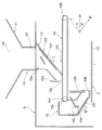
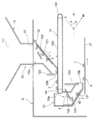
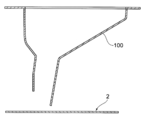
- 1 is a schematic configuration diagram of a tablet printing apparatus including the hopper. It is side sectional drawing of this hopper. It is a block diagram which shows the electrical structure which concerns on control of this hopper. It is the 1st side sectional view showing the flow of the tablet in this hopper. It is a 2nd side sectional view showing the flow of the tablet in this hopper. It is side sectional drawing of the conventional hopper.
- the present hopper 10 an embodiment of a hopper according to the present invention (hereinafter referred to as the present hopper 10) will be described with reference to FIGS.
- the present embodiment a case where the hopper 10 is applied to a tablet printing apparatus will be described.
- the tablet printing apparatus includes a tablet supply unit 1 to which tablets T are supplied, a tablet transport unit 2 that transports tablets T, and a tablet printing unit 3 that performs printing on the front and back surfaces of tablets T. And a tablet inspection unit 4 for inspecting the state of printing, cracking or chipping of the tablet T, and a tablet discharge unit 5 from which the tablet T is discharged.
- the tablet supply unit 1 includes a hopper 10 at the bottom of the base 6 as shown in FIG. For this reason, when a large amount of tablets T are charged into the main hopper 10, the tablets T pass through the inside of the main hopper 10 and then are discharged to the tablet transport unit 2. A specific configuration of the hopper 10 will be described in detail later.
- the tablet conveying unit 2 includes an upper conveyor 21 provided on the upper side of the apparatus, a reversing drum 22 provided at a terminal portion in the conveying direction of the upper conveyor 21, and a lower conveyor 23 provided on the lower side of the apparatus. With. For this reason, when the tablet T is discharged from the tablet supply unit 1, the tablet T is transported in a predetermined direction by the upper conveyor 21, and after the front and back surfaces are reversed by the reversing drum 22, the tablet T is transported in the reverse direction by the lower conveyor 23. Is done.
- the tablet printing unit 3 includes a front surface printing unit 31 provided on the upper conveyor 21 and a back surface printing unit 32 provided on the lower conveyor 23, both of which print tablets T by a non-contact method such as an inkjet method. To do. For this reason, the tablet T is printed with predetermined information on the front surface by the front surface printing unit 31 in the process of being conveyed by the upper conveyor 21, and predetermined by the back surface printing unit 32 in the process of being conveyed by the lower conveyor 23. Is printed on the back side.
- shape position detection units 33 and 34 for detecting the shape and position of the tablet T are provided at positions immediately before the front surface printing unit 31 and the back surface printing unit 32, respectively.
- the tablet inspection unit 4 includes a back surface inspection unit 41 provided above the lower conveyor 23 and a surface inspection unit 42 provided in the tablet discharge unit 5, and is in a tablet T state (a crack or chipping of the tablet T). Inspect printing misalignment / bleeding, no printing, etc.). For this reason, after the back surface of the tablet T is printed by the back surface printing unit 32 of the tablet printing unit 3, the state of the back surface of the tablet T is inspected by the back surface inspection unit 41, and the surface inspection unit 42 in the subsequent tablet discharge unit 5. Thus, the state of the surface of the tablet T is inspected.
- the tablet discharge unit 5 includes a suspension transport unit 51 that sucks and transports the tablets T, a non-defective tablet discharge unit 52 that transports non-defective tablets T, and a defective tablet discharge unit that discharges defective tablets T. 53. For this reason, in the process in which the tablets T are transported while being suspended by the suspension transport unit 51, the defective tablets T are discharged to the defective tablet discharge unit 53 based on the inspection result by the tablet inspection unit 4. On the other hand, the non-defective tablet T is discharged and conveyed to the non-defective tablet discharge unit 52.
- the hopper 10 includes a funnel-shaped first hopper portion 11 provided outside the base 6 in the tablet supply unit 1 and a rectangular cylindrical shape provided on the upper side in the base 6.
- a second hopper portion 12 (upper hopper portion), a rectangular cylindrical third hopper portion 13 (lower hopper portion) provided on the lower side of the base 6, a second hopper portion 12,
- the conveyance part 14 provided between the 3rd hopper parts 13 and the control part 15 which controls the conveyance part 14 are comprised.
- the first hopper portion 11 has a large-diameter tablet insertion port 111 formed at the upper end portion and a lower end portion connected to an opening 61 formed in the base 6. For this reason, when the tablet T is introduced into the insertion port 111 of the first hopper portion 11, the tablet T falls to the opening 61 inside the first hopper portion 11.
- the second hopper portion 12 has a supply port 12a connected to the opening 61 of the base 6 formed at the upper end portion, and extends downward in an inclined direction L behind the device with respect to the horizontal direction H, and at the rear of the device.
- a discharge port 12b that opens toward the bottom is formed at the lower end. For this reason, the tablet T supplied from the first hopper portion 11 through the supply port 12a falls along the inclination direction L in the second hopper portion 12 and is transferred from the discharge port 12b to the transport portion 14. Discharged.
- the inclination direction L of the second hopper 12 is set to an angle ⁇ in the range of 30 degrees to 60 degrees with respect to the horizontal direction H. Therefore, the tablet T falling from the supply port 12a gently falls along the predetermined inclination direction L inside the second hopper portion 12.
- the reason why the angle ⁇ in the inclination direction L of the second hopper 12 is set to 30 degrees or more with respect to the horizontal direction H is to drop the tablet T smoothly.
- the reason why the angle ⁇ in the inclination direction L of the second hopper 12 is set to 60 degrees or less with respect to the horizontal direction H is to prevent the tablet T from dropping at a stretch.
- the second hopper portion 12 is provided therein with an upper buffer sheet member 121, a product pressure reducing member 122, and an upper discharge amount adjusting gate member 123, respectively.
- the upper buffer sheet member 121 is a sheet-like elastic member formed in a rectangular shape in plan view, and is extended on the inner and lower surfaces of the upper part in the inclination direction of the second hopper portion 12. Thereby, the collision of the tablet T falling from the supply port 12a can be buffered.
- the accumulating pressure reducing member 122 is a plate-like elastic member formed in a rectangular shape in plan view, and is provided in a manner extending in the inclination direction L of the second hopper portion 12 inside the second hopper portion 12. ing.
- the stacked pressure reducing members 122 support the edible bodies stacked above, thereby loading the tablets T inside the second hopper portion 12. Pressure can be reduced.
- the upper discharge amount adjusting gate member 123 is a plate-like member formed in a rectangular shape in plan view, and is provided so as to be movable in the vertical direction at the discharge port 12b of the second hopper portion 12. Accordingly, when a predetermined gap is made between the upper discharge amount adjusting gate member 123 and the inner and lower surfaces of the second hopper 12 by moving the upper discharge amount adjustment gate member 123 upward, the tablets T Since a part of T can be sequentially passed through a predetermined gap, the discharge amount of the tablet T can be adjusted to such an extent that a large accumulated pressure is not applied to the tablet T stacked inside the second hopper 12.
- the third hopper portion 13 has a supply port 13a that opens toward the front of the device at the upper end, extends downward in the inclination direction M in front of the device with respect to the horizontal direction H, and at the lower end at the front of the device.
- a discharge port 13b that is open is formed. For this reason, after the tablet T supplied from the transport unit 14 via the supply port 13a falls downward from the supply port 13a, the tablet T falls along the inclination direction M of the third hopper 13, and the discharge port It is discharged from 13b to the tablet conveying section 2.
- the inclination direction M of the third hopper 13 is set to an angle ⁇ in the range of 30 to 60 degrees with respect to the horizontal direction H. Therefore, the tablet T that has fallen from the supply port 13a gently falls along the inclination direction M inside the third hopper portion 13.
- the reason why the angle ⁇ in the inclination direction M of the third hopper 13 is set to 30 degrees or more with respect to the horizontal direction H is to allow the tablet T to fall smoothly.
- the reason why the angle ⁇ in the inclination direction M of the third hopper 13 is set to 60 degrees or less with respect to the horizontal direction H is to prevent the tablet T from dropping at a stretch.
- the third hopper 13 is provided with a lower buffer sheet member 131, a collision reducing member 132, a lower discharge amount adjusting gate member 133, and a detection unit 134, respectively.
- the lower buffer sheet member 131 is a sheet-like elastic member formed in a rectangular shape in plan view, and is extended across the upper inner surface and the lower inner surface of the third hopper 13. Thereby, the collision of the tablet T falling from the supply port 13a can be buffered.
- the collision reducing member 132 is a plate-like elastic member formed in a rectangular shape in plan view, and is provided in a mode in which it is slightly inclined toward the rear of the device inside the upper side of the third hopper portion 13.
- the tablet T falling from the supply port 13a is once received by the collision reducing member 132 and decelerated, and further falls to the lower buffer sheet member 131.
- the collision with respect to the inner surface of the 3rd hopper part 13 of the tablet T can be reduced.
- the accumulated pressure of the tablets T inside the third hopper 13 is reduced by supporting the edible bodies stacked above them. You can also
- the lower discharge amount adjustment gate member 133 is a plate-like member formed in a rectangular shape in plan view, and is provided so as to be movable in the vertical direction at the discharge port 13b of the third hopper 13.
- the detection unit 134 includes an optical sensor that detects the tablets T stacked inside the third hopper unit 13, and is provided at a predetermined height position inside the third hopper unit 13. Thereby, when the tablet T more than predetermined height piles up in the inside of the 3rd hopper part 13, the detection part 134 detects the tablet T with an optical sensor, and transmits the detection result of the tablet T to the control part 15. To do.
- the transport unit 14 is a belt conveyor provided along the horizontal direction H, and includes a main driving shaft 141 disposed at the rear of the apparatus, a driven shaft 142 disposed at the front of the apparatus, and between the main driving shaft and the driven shaft. Is provided with a timing belt 143 wound in an endless state.
- the main drive shaft 141 is rotated in a predetermined direction (counterclockwise in FIG. 1) by the drive motor 141a in the transport unit 14, the timing belt 143 is rotated in a predetermined direction (counterclockwise in FIG. 1).
- the tablet T discharged onto the timing belt 143 from the discharge port 12b of the second hopper 12 is conveyed to the supply port 13a of the third hopper 13 according to the rotation of the timing belt 143 in the conveyance unit 14.
- the control unit 15 controls the conveyance of the tablet T by the conveyance unit 14. Specifically, as shown in FIG. 3, the control unit 15 is electrically connected to the detection unit 134 of the third hopper unit 13 and the drive motor 141 a of the main drive shaft 141 of the transport unit 14. The conveyance of the tablet T by the conveyance unit 14 is controlled by controlling the rotation of the drive motor 141 a of the main drive shaft 141 of the conveyance unit 14 based on the detection result of the tablet T by the detection unit 134 of the third hopper unit 13.
- the control unit 15 controls the drive motor 141 a to rotate at a predetermined speed, while detecting the tablet T from the detection unit 134.
- a control method for transmitting a control signal indicating that the drive motor 141a is to be stopped may be used. According to this, the conveyance part 14 can convey the tablet T on the timing belt 143, keeping the quantity of the tablet T in the 3rd hopper part 13 constant.
- FIG. 4 shows a flow when the tablet T is a small amount when the tablet is inserted.
- the tablet T falls inside the first hopper portion 11 to the opening 61.
- the tablet T supplied from the first hopper 11 through the supply port 12 a falls along the inclination direction L inside the second hopper 12 and is discharged. It is discharged from the outlet 12b to the transport unit 14.
- the upper buffer sheet member 121 of the first hopper 11 can buffer the collision of the tablet T falling from the supply port 12a.
- the tablet T discharged from the discharge port 12b of the second hopper 12 onto the timing belt 143 in the transport unit 14 is supplied to the supply port 13a of the third hopper 13 according to the rotation of the timing belt 143 in the transport unit 14. It is conveyed to.
- the tablet T that has fallen from the supply port 13a is once decelerated by being received by the collision reducing member 132, and further falls to the lower buffer sheet member 131. Therefore, the third hopper 13 of the tablet T is dropped. The collision with the inner surface of the can be reduced. Furthermore, the collision of the tablet T can be buffered by the lower buffer sheet member 131.
- FIG. 5 shows a flow when the tablet T is a large amount.
- the tablet T falls inside the first hopper portion 11 to the opening 61.
- the tablet T supplied from the first hopper 11 through the supply port 12 a falls along the inclination direction L inside the second hopper 12 and is discharged. It is discharged from the outlet 12b to the transport unit 14.
- the tablets T are in a large amount, they are sequentially stacked upward from the discharge port 12b of the second hopper 12. For this reason, when the tablet T is stacked above the stacked pressure reducing member 122, the stacked pressure reducing member 122 supports the edible body stacked above, thereby loading the tablet T inside the second hopper portion 12. Pressure can be reduced.
- the upper discharge amount adjustment gate member 123 can pass through a part of the tablets T sequentially from a predetermined gap while damming the tablets T stacked upward, so that they are stacked inside the second hopper 12.
- the discharge amount of the tablet T can be adjusted to such an extent that a large product pressure is not applied to the tablet T.
- the tablet T discharged from the discharge port 12b of the second hopper 12 onto the timing belt 143 in the transport unit 14 is supplied to the supply port 13a of the third hopper 13 according to the rotation of the timing belt 143 in the transport unit 14. It is conveyed to.
- the transport unit 14 is controlled by the control unit 15 to transport the tablets T.
- the tablet T is sequentially stacked upward from the discharge port 13b of the third hopper 13. For this reason, since the tablet T that has fallen from the supply port 13a is once received by the collision reducing member 132 and decelerated, the tablet T further falls onto the tablet T stacked on the lower cushioning sheet member 131. Collision with the tablet T can be reduced.
- the lower discharge amount adjustment gate member 133 can sequentially discharge a part of the tablet T from the predetermined gap while blocking the tablet T stacked upward, it is stacked inside the third hopper 13. It is possible to adjust the discharge amount of the tablet T to such an extent that a large product pressure is not applied to the tablet T.
- the detection unit 134 detects the tablets T with an optical sensor and transmits the detection results of the tablets T to the control unit 15. . Then, the control unit 15 controls the rotation of the drive motor 141a of the main drive shaft 141 of the transport unit 14 based on the detection result of the tablet T by the detection unit 134 of the third hopper unit 13, and thereby the transport unit 14 Since the conveyance of the tablet T is controlled, the amount of the tablet T inside the third hopper 13 can be made constant.
- the collision of the tablet T due to the drop can be reduced.
- the tablets T are stacked in the second hopper portion 12 and the third hopper portion 13, the accumulated pressure of the tablets T can be reduced. Therefore, it is possible to reduce the occurrence of defects such as cracks and chips in the tablet T due to the collision of the tablet T due to the drop and the accumulated pressure of the tablet T.
- control unit 15 controls the transport of the tablets T by the transport unit 14 based on the amount of the tablets T stacked inside the third hopper unit 13, so that the tablets inside the third hopper unit 13. Since the amount of T can be made constant, the product pressure of the tablet T can be reliably reduced.
- the transport of the tablet T by the transport unit 14 is controlled based on the amount of the tablet T stacked inside the third hopper 13, but in addition to or instead of the control, the first The conveyance of the tablet T by the conveyance unit 14 may be controlled based on the amount of the tablet T stacked inside the two hopper units 12.
- the detection unit 134 that detects the tablet T at a predetermined height position inside the third hopper 13 is used. May be used.
Landscapes
- Health & Medical Sciences (AREA)
- Chemical & Material Sciences (AREA)
- Medicinal Chemistry (AREA)
- Engineering & Computer Science (AREA)
- Mechanical Engineering (AREA)
- Pharmacology & Pharmacy (AREA)
- Life Sciences & Earth Sciences (AREA)
- Animal Behavior & Ethology (AREA)
- General Health & Medical Sciences (AREA)
- Public Health (AREA)
- Veterinary Medicine (AREA)
- Medical Preparation Storing Or Oral Administration Devices (AREA)
Abstract
本発明は、落下による衝撃や可食体の積圧によって可食体に割れや欠け等の欠損が生じることを軽減することができるホッパー、並びに該ホッパーが用いられる錠剤印刷装置を提供することを目的とする。所定の傾斜方向で下方に延びる態様で設けられた筒状の第2のホッパー部12(上側ホッパー部)と、第2のホッパー部12と逆の傾斜方向で下方に延びる態様で設けられた筒状の第3のホッパー部13(下側ホッパー部)と、第2のホッパー部12と第3のホッパー部13との間に設けられ、第2のホッパー部12から排出された錠剤Tを第3のホッパー部13に搬送する搬送部14と、搬送部14による錠剤Tの搬送を制御する制御部15とを備える。
Description
本発明は、錠剤やカプセル等の経口投与剤および食品等の可食体を供給する際に用いられるホッパー、および該ホッパーが用いられる錠剤印刷装置に関するものである。
近年、 医療分野において、薬剤師による調剤ミスや患者による誤服用などの医療事故を防止するために、インクジェットプリンタにより錠剤の表面にインクを噴射して印刷を行う錠剤印刷装置が知られている。
一般に、この錠剤印刷装置は、錠剤が供給される錠剤供給部と、錠剤を搬送する錠剤搬送部と、錠剤の表面に印刷を行う錠剤印刷部と、錠剤の印刷、割れあるいは欠け等の状態を検査する錠剤検査部と、錠剤が排出される錠剤排出部とから構成される。これによると、錠剤に対して非接触で印刷処理を行うことができ、FC錠や糖衣錠のみならず、素錠の場合でも、鮮明な印刷処理が可能である。
このうち錠剤供給部について具体的に説明すると、図6に示すように、主に漏斗状のホッパー100により構成されており、ホッパー100に錠剤が投入されると、ホッパー100の内部を落下しながら通過して、錠剤搬送部2に排出される。
ところが、従来のホッパーにおいて錠剤が投入されると、錠剤が錠剤搬送部まで一気に落下して、錠剤がホッパーの内面や他の錠剤に衝突して割れや欠けが生じる場合があった。また、大量の錠剤が投入されると、錠剤がホッパーの内部において塊状に積み重なった状態となり、積み重なった錠剤の重み(積圧)によって、錠剤に割れや欠けが生じる場合があった。
そこで、特許文献1に示すように、落下による錠剤の衝突を軽減させ、錠剤に割れや欠け等の欠損が生じることを軽減するホッパーが提案されている。
しかしながら、この従来の錠剤供給装置によっても、落下による錠剤の衝突を十分に軽減することができず、また大量に積み重なった錠剤の積圧による割れや欠け等の欠損はほとんど軽減することができなかった。このような問題は、錠剤のみに限られるものではなく、カプセル等の経口投与剤および食品等の可食体にも同様に生じるものであった。
本発明は、上述の問題に鑑みてなされたものであり、落下による可食体の衝突や可食体の積圧によって、可食体に割れや欠け等の欠損が生じることを軽減することができるホッパー、並びに該ホッパーが用いられる錠剤印刷装置を提供することを目的とする。
本発明は、上記目的を達成するために、錠剤やカプセル等の経口投与剤および食品等の可食体を供給する際に用いられるホッパーであって、所定の傾斜方向で下方に延びる態様で設けられた筒状の上側ホッパー部と、該上側ホッパー部と同一または異なる傾斜方向で下方に延びる態様で設けられた筒状の下側ホッパー部と、上側ホッパー部と下側ホッパー部との間に設けられ、上側ホッパー部から排出された可食体を下側ホッパー部に搬送する搬送部と、前記搬送部による可食体の搬送を制御する制御部とを備えることを特徴とする。
これによれば、可食体は、上側ホッパー部の内部を落下して排出され、搬送部により上側ホッパー部から下側ホッパー部に搬送されたあと、下側ホッパー部の内部を落下して排出される。このように上側ホッパー部と下側ホッパー部に分けて可食体を落下させるため、落下による可食体の衝突を軽減することができる。また、上側ホッパー部と下側ホッパー部に分けて可食体を積み重ねるため、可食体の積圧を軽減することができる。よって、落下による可食体の衝突や可食体の積圧によって、可食体に割れや欠け等の欠損が生じることを軽減することが可能となる。
また、前記制御部は、前記上側ホッパー部および/または前記下側ホッパー部の内部に積み重なった可食体の量に基づいて、前記搬送部による可食体の搬送を制御してもよい。これによれば、上側ホッパー部や下側ホッパー部における可食体の量を調整し得るため、上側ホッパー部や下側ホッパー部の内部における可食体の積圧を軽減することができる。
また、前記上側ホッパー部および/または下側ホッパー部の内部における所定の高さ位置において、可食体を検知する検知部が設けられ、前記制御部は、前記検知部による可食体の検知結果に基づいて、前記搬送部による可食体の搬送を制御してもよい。これによれば、簡易な構成にして、上側ホッパー部および/または下側ホッパー部における可食体の量を調整することができる。
また、前記下側ホッパー部は、前記上側ホッパー部と反対の傾斜方向で下方に延びる態様で設けられていてもよい。ホッパーの全体の長さを長くすることなく、上側ホッパー部と下側ホッパー部の傾斜方向を緩やかに構成し得るため、可食体を緩やかに落下させることができる。
また、前記上側ホッパー部は、上方に積み重なった可食体を支承することにより可食体の積圧を軽減する積圧軽減部材が設けられていてもよい。これによれば、可食体の積圧を軽減することができる。
また、前記上側ホッパー部は、傾斜方向上部の内面において、上方から落下してきた可食体の衝突を緩衝する上側緩衝シート部材が設けられていてもよい。これによれば、上方から落下してきた可食体の衝突を緩衝することができる。
また、前記上側ホッパー部は、可食体が排出される排出口において、可食体の排出量を調整する上側排出量調整ゲート部材が設けられていてもよい。これによれば、可食体の排出量を調整することができる。
また、前記下側ホッパー部は、傾斜方向上部の内面において、上方から落下してきた可食体の衝突を緩衝する下側緩衝シート部材が設けられていてもよい。これによれば、上方から落下してきた可食体の衝突を緩衝することができる。
また、前記下側ホッパー部は、可食体が供給される供給口の下方において、上方から落下してきた可食体を受け止めることにより可食体の衝突を軽減する衝突軽減部材が設けられていてもよい。投入口から落下してきた可食体の衝突を軽減することができる。
また、前記下側ホッパー部は、可食体が排出される排出口において、可食体の排出量を調整する下側排出量調整ゲート部材が設けられていてもよい。これによれば、可食体の排出量を調整することができる。
また、本発明に係る錠剤印刷装置は、前記ホッパーが設けられていることを特徴とする。
本発明によれば、可食体は、上側ホッパー部の内部を落下して排出され、搬送部により上側ホッパー部から下側ホッパー部に搬送されたあと、下側ホッパー部の内部を落下して排出される。このように上側ホッパー部と下側ホッパー部に分けて可食体を落下させるため、落下による可食体の衝突を軽減することができる。また、上側ホッパー部と下側ホッパー部に分けて可食体を積み重ねるため、可食体の積圧を軽減することができる。よって、落下による可食体の衝突や可食体の積圧によって可食体に割れや欠け等の欠損が生じることを軽減することが可能となる。このため、例えば本ホッパーを錠剤印刷装置に適用した場合、割れや欠け等の欠損のない品質の高い錠剤を効率的に製造することが可能となる。
次に、本発明に係るホッパー(以下、本ホッパー10という)の実施形態について図1~図5を参照しつつ説明する。なお、本実施形態では、本ホッパー10を錠剤印刷装置に適用した場合について説明する。
この錠剤印刷装置は、図1に示すように、錠剤Tが供給される錠剤供給部1と、錠剤Tを搬送する錠剤搬送部2と、錠剤Tの表面及び裏面に印刷を行う錠剤印刷部3と、錠剤Tの印刷、割れあるいは欠け等の状態を検査する錠剤検査部4と、錠剤Tが排出される錠剤排出部5とから構成される。
前記錠剤供給部1は、図2に示すように、基台6の下部において本ホッパー10を備える。このため、本ホッパー10に大量の錠剤Tが投入されると、錠剤Tが本ホッパー10の内部を通過したあと、錠剤搬送部2に排出される。本ホッパー10の具体的な構成については後に詳述する。
前記錠剤搬送部2は、装置の上側に設けられた上側コンベア21と、該上側コンベア21の搬送方向の末端部に設けられた反転ドラム22と、装置の下側に設けられた下側コンベア23とを備える。このため、錠剤供給部1から錠剤Tが排出されると、錠剤Tが上側コンベア21により所定の方向に搬送され、反転ドラム22において表裏面が反転したあと、下側コンベア23により逆方向に搬送される。
前記錠剤印刷部3は、上側コンベア21に設けられた表面印刷部31と、下側コンベア23に設けられた裏面印刷部32とを備え、いずれもインクジェット方式等の非接触方式で錠剤Tを印刷するものである。このため、錠剤Tは、上側コンベア21により搬送される過程において、表面印刷部31により所定の情報が表面に印刷されるとともに、下側コンベア23により搬送される過程において、裏面印刷部32により所定の情報が裏面に印刷される。なお、表面印刷部31および裏面印刷部32の直前の位置には、錠剤Tの形状や位置を検出するための形状位置検出部33、34がそれぞれ設けられている。
前記錠剤検査部4は、下側コンベア23の上方に設けられた裏面検査部41と、錠剤排出部5に設けられた表面検査部42とを備え、錠剤Tの状態(錠剤Tの割れ、欠け、印刷の位置ずれ・にじみ、無印刷など)を検査する。このため、錠剤Tは、錠剤印刷部3の裏面印刷部32により裏面を印刷されたあと、裏面検査部41により錠剤Tの裏面の状態が検査され、後の錠剤排出部5における表面検査部42により錠剤Tの表面の状態が検査される。
前記錠剤排出部5は、錠剤Tを吸着して吊りながら搬送する吊り搬送部51と、良品の錠剤Tを搬送する良品錠剤排出部52と、不良品の錠剤Tを排出する不良品錠剤排出部53とを備える。このため、錠剤Tは、吊り搬送部51により吊られながら搬送される過程において、前記錠剤検査部4による検査結果に基づいて、不良品の錠剤Tについては不良品錠剤排出部53に排出される一方、良品の錠剤Tについては良品錠剤排出部52に排出されて搬送される。
次に、錠剤供給部1に用いられる本ホッパー10について、図2~図5を参照つつ具体的に説明することとする。
本ホッパー10は、図2に示すように、錠剤供給部1において基台6外に設けられた漏斗状の第1のホッパー部11と、基台6内の上側に設けられた矩形筒状の第2のホッパー部12(上側ホッパー部)と、同じく基台6内の下側に設けられた矩形筒状の第3のホッパー部13(下側ホッパー部)と、第2のホッパー部12と第3のホッパー部13の間に設けられた搬送部14と、搬送部14を制御する制御部15とから構成される。
前記第1のホッパー部11は、上端部に径大の錠剤投入口111が形成されるとともに、下端部が基台6に形成された開口部61に接続されている。このため、第1のホッパー部11の投入口111に錠剤Tが投入されると、錠剤Tが第1のホッパー部11の内部を開口部61まで落下していく。
前記第2のホッパー部12は、基台6の開口部61に接続される供給口12aが上端部に形成され、水平方向Hに対して装置後方の傾斜方向Lで下方に延びるとともに、装置後方に向けて開口した排出口12bが下端部に形成されている。このため、第1のホッパー部11から供給口12aを介して供給された錠剤Tは、第2のホッパー部12の内部を傾斜方向Lに沿って落下して、排出口12bから搬送部14に排出される。
特に本実施形態では、第2のホッパー部12の傾斜方向Lは、水平方向Hに対して30度~60度の範囲内の角度αとなされている。よって、供給口12aから落下してきた錠剤Tは、第2のホッパー部12の内部を所定の傾斜方向Lに沿って緩やかに落下する。なお、第2のホッパー部12の傾斜方向Lの角度αを水平方向Hに対して30度以上としたのは、錠剤Tをスムーズに落下させるためである。一方、第2のホッパー部12の傾斜方向Lの角度αを水平方向Hに対して60度以下としたのは、錠剤Tが一気に落下することを防止するためである。
また、前記第2のホッパー部12は、内部において上側緩衝シート部材121、積圧軽減部材122および上側排出量調整ゲート部材123がそれぞれ設けられている。
前記上側緩衝シート部材121は、平面視矩形状に形成されたシート状の弾性部材であり、第2のホッパー部12の傾斜方向上部の内下面に展設されている。これにより、供給口12aから落下してきた錠剤Tの衝突を緩衝することができる。
前記積圧軽減部材122は、平面視矩形状に形成された板状の弾性部材であり、第2のホッパー部12の上側内部において第2のホッパー部12の傾斜方向Lに延びる態様で設けられている。これにより、錠剤Tが積圧軽減部材122の上方まで積み重なった場合、積圧軽減部材122が上方に積み重なった可食体を支承することにより、第2のホッパー部12の内部における錠剤Tの積圧を軽減することができる。
前記上側排出量調整ゲート部材123は、平面視矩形状に形成された板状部材であり、第2のホッパー部12の排出口12bにおいて上下方向に移動可能に設けられている。これにより、上側排出量調整ゲート部材123を上方に移動させることにより第2のホッパー部12の内下面との間に所定の隙間を空けると、上方に積み重なった錠剤Tを堰き止めながら、当該錠剤Tの一部を所定の隙間から順次通過させ得るため、第2のホッパー部12の内部に積み重なった錠剤Tに大きな積圧がかからない程度に錠剤Tの排出量を調整することができる。
前記第3のホッパー部13は、装置前方に向けて開口した供給口13aが上端部に形成され、水平方向Hに対して装置前方の傾斜方向Mで下方に延びるとともに、下端部に装置前方に向けて開口した排出口13bが形成されている。このため、搬送部14から供給口13aを介して供給された錠剤Tは、該供給口13aから下方に落下したあと、第3のホッパー部13の傾斜方向Mに沿って落下して、排出口13bから錠剤搬送部2に排出される。
特に本実施形態では、第3のホッパー部13の傾斜方向Mが、水平方向Hに対して30度~60度の範囲内の角度βとなされている。よって、供給口13aから落下してきた錠剤Tは、第3のホッパー部13の内部を傾斜方向Mに沿って緩やかに落下する。なお、第3のホッパー部13の傾斜方向Mの角度βを水平方向Hに対して30度以上としたのは、錠剤Tをスムーズに落下させるためである。一方、第3のホッパー部13の傾斜方向Mの角度βを水平方向Hに対して60度以下としたのは、錠剤Tが一気に落下することを防止するためである。
また、前記第3のホッパー部13は、内部において下側緩衝シート部材131、衝突軽減部材132、下側排出量調整ゲート部材133および検知部134がそれぞれ設けられている。
前記下側緩衝シート部材131は、平面視矩形状に形成されたシート状の弾性部材であり、第3のホッパー部13の上部の内側面と下部の内下面に亘って展設されている。これにより、供給口13aから落下してきた錠剤Tの衝突を緩衝することができる。
前記衝突軽減部材132は、平面視矩形状に形成された板状の弾性部材であり、第3のホッパー部13の上側内部において装置後方に向けてやや傾斜する態様で設けられている。これにより、供給口13aから落下してきた錠剤Tは、一旦、衝突軽減部材132に受け止められて減速したあと、さらに下側緩衝シート部材131に落下する。これにより錠剤Tの第3のホッパー部13の内面に対する衝突を軽減することができる。また、万一、錠剤Tが衝突軽減部材132の上方まで積み重なった場合でも、それら上方に積み重なった可食体を支承することにより、第3のホッパー部13の内部における錠剤Tの積圧を軽減することもできる。
前記下側排出量調整ゲート部材133は、平面視矩形状に形成された板状部材であり、第3のホッパー部13の排出口13bにおいて上下方向に移動可能に設けられている。これにより、下側排出量調整ゲート部材133を上方に移動させることにより第3のホッパー部13の内下面との間に所定の隙間を空けると、上方に積み重なった錠剤Tを堰き止めながら、当該錠剤Tの一部を所定の隙間から順次排出し得るため、第3のホッパー部13の内部に積み重なった錠剤Tに大きな積圧がかからない程度に錠剤Tの排出量を調整することができる。
前記検知部134は、第3のホッパー部13の内部に積み重なる錠剤Tを検知する光学センサを備え、第3のホッパー部13の内部における所定の高さ位置に設けられている。これにより、第3のホッパー部13の内部に所定の高さ以上の錠剤Tが積み重なった場合、検知部134が光学センサにより錠剤Tを検知して、錠剤Tの検知結果を制御部15に送信する。
前記搬送部14は、水平方向Hに沿って設けられたベルトコンベアであって、装置後方に配置された主動軸141と、装置前方に配置された従動軸142と、主動軸と従動軸の間を無端状態に巻架されたタイミングベルト143を備える。而して、搬送部14において、駆動モータ141aにより主動軸141が所定の方向(図1の左回り)に回転すると、タイミングベルト143が所定の方向(図1の左回り)に回転する。このため、第2のホッパー部12の排出口12bからタイミングベルト143上に排出された錠剤Tは、搬送部14におけるタイミングベルト143の回転に従って、第3のホッパー部13の供給口13aまで搬送される。
前記制御部15は、搬送部14による錠剤Tの搬送を制御する。具体的には、制御部15は、図3に示すように、第3のホッパー部13の検知部134と、搬送部14の主動軸141の駆動モータ141aに電気的に接続されており、第3のホッパー部13の検知部134による錠剤Tの検知結果に基づいて、搬送部14の主動軸141の駆動モータ141aの回転を制御することにより、搬送部14による錠剤Tの搬送を制御する。
例えば、制御部15は、検知部134から錠剤Tを検出した旨の信号を受信しない状態においては、駆動モータ141aを所定速度で回転するように制御する一方、検知部134から錠剤Tを検出した旨の信号を受信した状態においては、駆動モータ141aを停止する旨の制御信号を送信する制御方法が挙げられる。これによれば、搬送部14は、第3のホッパー部13における錠剤Tの量を一定に保ちながら、タイミングベルト143上の錠剤Tを搬送することができる。
次に本ホッパー10における錠剤Tの流れについて図4および図5を参照しつつ説明する。
図4は、錠剤投入時等において錠剤Tが少量の場合の流れを示す。
まず、第1のホッパー部11において、投入口111に少量の錠剤Tが投入されると、錠剤Tが第1のホッパー部11の内部を開口部61まで落下していく。
そして、第2のホッパー部12において、第1のホッパー部11から供給口12aを介して供給された錠剤Tは、第2のホッパー部12の内部を傾斜方向Lに沿って落下して、排出口12bから搬送部14に排出される。
このとき、第1のホッパー部11の上側緩衝シート部材121により、供給口12aから落下してきた錠剤Tの衝突を緩衝することができる。
そして、搬送部14において、第2のホッパー部12の排出口12bからタイミングベルト143上に排出された錠剤Tは、搬送部14におけるタイミングベルト143の回転に従って第3のホッパー部13の供給口13aまで搬送される。
そして、第3のホッパー部13において、搬送部14から供給口13aを介して供給された錠剤Tは、該供給口13aから下方に落下したあと、第3のホッパー部13の傾斜方向Mに沿って落下して、排出口13bから錠剤搬送部2に排出される。
このとき、供給口13aから落下してきた錠剤Tは、一旦、衝突軽減部材132に受け止められることにより減速したあと、さらに下側緩衝シート部材131に落下するため、錠剤Tの第3のホッパー部13の内面に対する衝突を軽減することができる。さら、下側緩衝シート部材131により錠剤Tの衝突を緩衝することができる。
図5は、錠剤Tが大量の場合の流れを示す。
まず、第1のホッパー部11において、投入口111に大量の錠剤Tが投入されると、錠剤Tが第1のホッパー部11の内部を開口部61まで落下していく。
そして、第2のホッパー部12において、第1のホッパー部11から供給口12aを介して供給された錠剤Tは、第2のホッパー部12の内部を傾斜方向Lに沿って落下して、排出口12bから搬送部14に排出される。
このとき、錠剤Tは大量であることから、第2のホッパー部12の排出口12bから上方に順次積み重なった状態となる。このため、錠剤Tが積圧軽減部材122の上方まで積み重なった場合、積圧軽減部材122が上方に積み重なった可食体を支承することにより、第2のホッパー部12の内部における錠剤Tの積圧を軽減することができる。
また、上側排出量調整ゲート部材123が、上方に積み重なった錠剤Tを堰き止めながら、当該錠剤Tの一部を所定の隙間から順次通過させ得るため、第2のホッパー部12の内部に積み重なった錠剤Tに大きな積圧がかからない程度に錠剤Tの排出量を調整することができる。
そして、搬送部14において、第2のホッパー部12の排出口12bからタイミングベルト143上に排出された錠剤Tは、搬送部14におけるタイミングベルト143の回転に従って第3のホッパー部13の供給口13aまで搬送される。なお、後述するように、搬送部14は制御部15により錠剤Tの搬送を制御される。
そして、第3のホッパー部13において、搬送部14から供給口13aを介して供給された錠剤Tは、該供給口13aから下方に落下したあと、第3のホッパー部13の傾斜方向Mに沿って落下して、排出口13bから錠剤搬送部2に排出される。
このとき、錠剤Tは大量であることから、第3のホッパー部13の排出口13bから上方に順次積み重なった状態となる。このため、供給口13aから落下してきた錠剤Tは、一旦、衝突軽減部材132に受け止められて減速したあと、さらに下側緩衝シート部材131上に積み重なった錠剤Tに落下するため、錠剤Tの他の錠剤Tに対する衝突を軽減することができる。
また、下側排出量調整ゲート部材133が、上方に積み重なった錠剤Tを堰き止めながら、当該錠剤Tの一部を所定の隙間から順次排出し得るため、第3のホッパー部13の内部に積み重なった錠剤Tに大きな積圧がかからない程度に錠剤Tの排出量を調整することができる。
また、第3のホッパー部13の内部に所定の高さ以上の錠剤Tが積み重なった場合、検知部134が光学センサにより錠剤Tを検知して、錠剤Tの検知結果を制御部15に送信する。そして、制御部15が、第3のホッパー部13の検知部134による錠剤Tの検知結果に基づいて、搬送部14の主動軸141の駆動モータ141aの回転を制御することにより、搬送部14による錠剤Tの搬送を制御するため、第3のホッパー部13の内部における錠剤Tの量を一定にすることができる。
以上のとおり、第2のホッパー部12と第3のホッパー部13に分けて錠剤Tを落下させるため、落下による錠剤Tの衝突を軽減することができる。また、第2のホッパー部12と第3のホッパー部13に分けて錠剤Tを積み重ねるため、錠剤Tの積圧を軽減することができる。よって、落下による錠剤Tの衝突や錠剤Tの積圧によって、錠剤Tに割れや欠け等の欠損が生じることを軽減することが可能となる。
しかも、制御部15は、第3のホッパー部13の内部に積み重なった錠剤Tの量に基づいて、搬送部14による錠剤Tの搬送を制御することにより、第3のホッパー部13の内部における錠剤Tの量を一定にし得るため、錠剤Tの積圧を確実に軽減することができる。
なお、本実施形態では、第3のホッパー部13の内部に積み重なった錠剤Tの量に基づいて搬送部14による錠剤Tの搬送を制御するものとしたが、それと共に、あるいはそれに代えて、第2のホッパー部12の内部に内部に積み重なった錠剤Tの量に基づいて搬送部14による錠剤Tの搬送を制御してもよい。
また、第3のホッパー部13の内部における錠剤Tの量を推し量るのに、第3のホッパー部13の内部における所定高さ位置において錠剤Tを検知する検知部134を用いたが、その他の方法を用いてもよい。
以上、図面を参照して本発明の実施形態を説明したが、本発明は、図示した実施形態のものに限定されない。図示された実施形態に対して、本発明と同一の範囲内において、あるいは均等の範囲内において、種々の修正や変形を加えることが可能である。
1・・・錠剤供給部
10・・・本ホッパー
11・・・第1のホッパー部
111・・・錠剤投入口
12・・・第2のホッパー部(上側ホッパー部)
121・・・上側緩衝シート部材
122・・・積圧軽減部材
123・・・上側排出量調整ゲート部材
13・・・第3のホッパー部(下側ホッパー部)
131・・・下側緩衝シート部材
132・・・衝突軽減部材
133・・・下側排出量調整ゲート部材
134・・・検知部
14・・・搬送部
141・・・主動軸
142・・・従動軸
143・・・タイミングベルト
15・・・制御部
2・・・錠剤搬送部
3・・・錠剤印刷部
4・・・錠剤検査部
5・・・錠剤排出部
6・・・基台
61・・・開口部
10・・・本ホッパー
11・・・第1のホッパー部
111・・・錠剤投入口
12・・・第2のホッパー部(上側ホッパー部)
121・・・上側緩衝シート部材
122・・・積圧軽減部材
123・・・上側排出量調整ゲート部材
13・・・第3のホッパー部(下側ホッパー部)
131・・・下側緩衝シート部材
132・・・衝突軽減部材
133・・・下側排出量調整ゲート部材
134・・・検知部
14・・・搬送部
141・・・主動軸
142・・・従動軸
143・・・タイミングベルト
15・・・制御部
2・・・錠剤搬送部
3・・・錠剤印刷部
4・・・錠剤検査部
5・・・錠剤排出部
6・・・基台
61・・・開口部
Claims (11)
- 錠剤やカプセル等の経口投与剤および食品等の可食体を供給する際に用いられるホッパーであって、
所定の傾斜方向で下方に延びる態様で設けられた筒状の上側ホッパー部と、
該上側ホッパー部と同一または異なる傾斜方向で下方に延びる態様で設けられた筒状の下側ホッパー部と、
上側ホッパー部と下側ホッパー部との間に設けられ、上側ホッパー部から排出された可食体を下側ホッパー部に搬送する搬送部と、
前記搬送部による可食体の搬送を制御する制御部とを備えることを特徴とするホッパー。 - 前記制御部は、前記上側ホッパー部および/または前記下側ホッパー部の内部に積み重なった可食体の量に基づいて、前記搬送部による可食体の搬送を制御する請求項1に記載のホッパー。
- 前記上側ホッパー部および/または下側ホッパー部の内部における所定の高さ位置において、可食体を検知する検知部が設けられ、
前記制御部は、前記検知部による可食体の検知結果に基づいて、前記搬送部による可食体の搬送を制御する請求項2に記載のホッパー。 - 前記下側ホッパー部は、前記上側ホッパー部と反対の傾斜方向で下方に延びる態様で設けられている請求項1に記載のホッパー。
- 前記上側ホッパー部は、上方に積み重なった可食体を支承することにより可食体の積圧を軽減する積圧軽減部材が設けられている請求項1に記載のホッパー。
- 前記上側ホッパー部は、傾斜方向上部の内面において、上方から落下してきた可食体の衝突を緩衝する上側緩衝シート部材が設けられている請求項1に記載のホッパー。
- 前記上側ホッパー部は、可食体が排出される排出口において、可食体の排出量を調整する上側排出量調整ゲート部材が設けられている請求項1に記載のホッパー。
- 前記下側ホッパー部は、傾斜方向上部の内面において、上方から落下してきた可食体の衝突を緩衝する下側緩衝シート部材が設けられている請求項1に記載のホッパー。
- 前記下側ホッパー部は、可食体が供給される供給口の下方において、上方から落下してきた可食体を受け止めることにより可食体の衝突を軽減する衝突軽減部材が設けられている請求項1に記載のホッパー。
- 前記下側ホッパー部は、可食体が排出される排出口において、可食体の排出量を調整する下側排出量調整ゲート部材が設けられている請求項1に記載のホッパー。
- 請求項1に記載のホッパーが設けられていることを特徴とする錠剤印刷装置。
Applications Claiming Priority (2)
| Application Number | Priority Date | Filing Date | Title |
|---|---|---|---|
| JP2016-092327 | 2016-05-02 | ||
| JP2016092327A JP2017200502A (ja) | 2016-05-02 | 2016-05-02 | ホッパーおよび錠剤印刷装置 |
Publications (1)
| Publication Number | Publication Date |
|---|---|
| WO2017191753A1 true WO2017191753A1 (ja) | 2017-11-09 |
Family
ID=60202911
Family Applications (1)
| Application Number | Title | Priority Date | Filing Date |
|---|---|---|---|
| PCT/JP2017/015623 Ceased WO2017191753A1 (ja) | 2016-05-02 | 2017-04-18 | ホッパーおよび錠剤印刷装置 |
Country Status (2)
| Country | Link |
|---|---|
| JP (1) | JP2017200502A (ja) |
| WO (1) | WO2017191753A1 (ja) |
Citations (6)
| Publication number | Priority date | Publication date | Assignee | Title |
|---|---|---|---|---|
| JPS56107723U (ja) * | 1980-01-17 | 1981-08-21 | ||
| JPS58125192U (ja) * | 1982-02-19 | 1983-08-25 | 株式会社日本アルミ | 粉粒体貯蔵容器のブロツク現象防止機構 |
| JPH07309411A (ja) * | 1993-09-07 | 1995-11-28 | Takeda Chem Ind Ltd | 固形物搬送装置 |
| JP2000264442A (ja) * | 1999-03-23 | 2000-09-26 | Japan Steel Works Ltd:The | ゲート開度自動調節機能付きベルトフィーダ |
| JP2002308444A (ja) * | 2001-04-12 | 2002-10-23 | Unitec:Kk | 供給装置 |
| JP2013121432A (ja) * | 2011-12-09 | 2013-06-20 | Kyoto Seisakusho Co Ltd | 錠剤印刷装置 |
Family Cites Families (1)
| Publication number | Priority date | Publication date | Assignee | Title |
|---|---|---|---|---|
| JP5818671B2 (ja) * | 2011-12-19 | 2015-11-18 | クオリカプス株式会社 | 選別搬送装置 |
-
2016
- 2016-05-02 JP JP2016092327A patent/JP2017200502A/ja active Pending
-
2017
- 2017-04-18 WO PCT/JP2017/015623 patent/WO2017191753A1/ja not_active Ceased
Patent Citations (6)
| Publication number | Priority date | Publication date | Assignee | Title |
|---|---|---|---|---|
| JPS56107723U (ja) * | 1980-01-17 | 1981-08-21 | ||
| JPS58125192U (ja) * | 1982-02-19 | 1983-08-25 | 株式会社日本アルミ | 粉粒体貯蔵容器のブロツク現象防止機構 |
| JPH07309411A (ja) * | 1993-09-07 | 1995-11-28 | Takeda Chem Ind Ltd | 固形物搬送装置 |
| JP2000264442A (ja) * | 1999-03-23 | 2000-09-26 | Japan Steel Works Ltd:The | ゲート開度自動調節機能付きベルトフィーダ |
| JP2002308444A (ja) * | 2001-04-12 | 2002-10-23 | Unitec:Kk | 供給装置 |
| JP2013121432A (ja) * | 2011-12-09 | 2013-06-20 | Kyoto Seisakusho Co Ltd | 錠剤印刷装置 |
Also Published As
| Publication number | Publication date |
|---|---|
| JP2017200502A (ja) | 2017-11-09 |
Similar Documents
| Publication | Publication Date | Title |
|---|---|---|
| US10596811B2 (en) | Tablet printing apparatus and tablet printing method | |
| US10525699B2 (en) | Tablet printing device | |
| TWI427023B (zh) | A vibration supply device, a conveyance device, and a visual inspection device | |
| US20080307757A1 (en) | Device for Conveying Tablets | |
| JP5934268B2 (ja) | 複合処理システム | |
| JP2010247154A (ja) | 排出システム | |
| JP2022079495A (ja) | 錠剤印刷装置 | |
| JP6723818B2 (ja) | 錠剤印刷装置 | |
| TWI732600B (zh) | 搬送裝置及錠劑印刷裝置 | |
| JP6582421B2 (ja) | 物品分配投入装置 | |
| JP6693779B2 (ja) | 錠剤搬送装置及び錠剤印刷装置 | |
| KR20200034594A (ko) | 반송 장치 및 반송 방법 | |
| WO2017191751A1 (ja) | 錠剤印刷装置 | |
| KR20160039791A (ko) | 물품이송장치 | |
| JP2017200502A (ja) | ホッパーおよび錠剤印刷装置 | |
| JP6884506B2 (ja) | ホッパーおよび錠剤印刷装置 | |
| US11851286B2 (en) | Air assisted hopper system for pellet-shaped articles | |
| JP6399588B2 (ja) | キャップ供給装置 | |
| JP3477530B2 (ja) | 扁平容器の供給整列装置 | |
| KR102183819B1 (ko) | 김 계수장치 | |
| JP7023216B2 (ja) | 錠剤印刷装置 | |
| JP7221014B2 (ja) | 計数充填装置 | |
| JP6835673B2 (ja) | 錠剤印刷装置 | |
| JP2021021743A (ja) | 容器検査装置 | |
| JP2017048019A (ja) | 加工不良段ボールシート排除装置 |
Legal Events
| Date | Code | Title | Description |
|---|---|---|---|
| NENP | Non-entry into the national phase |
Ref country code: DE |
|
| 121 | Ep: the epo has been informed by wipo that ep was designated in this application |
Ref document number: 17792686 Country of ref document: EP Kind code of ref document: A1 |
|
| 122 | Ep: pct application non-entry in european phase |
Ref document number: 17792686 Country of ref document: EP Kind code of ref document: A1 |