WO2017191756A1 - バンド引張装置 - Google Patents
バンド引張装置 Download PDFInfo
- Publication number
- WO2017191756A1 WO2017191756A1 PCT/JP2017/015702 JP2017015702W WO2017191756A1 WO 2017191756 A1 WO2017191756 A1 WO 2017191756A1 JP 2017015702 W JP2017015702 W JP 2017015702W WO 2017191756 A1 WO2017191756 A1 WO 2017191756A1
- Authority
- WO
- WIPO (PCT)
- Prior art keywords
- band
- rotating body
- cutting
- tensioning device
- gripping
- Prior art date
- Legal status (The legal status is an assumption and is not a legal conclusion. Google has not performed a legal analysis and makes no representation as to the accuracy of the status listed.)
- Ceased
Links
Images

Classifications
-
- B—PERFORMING OPERATIONS; TRANSPORTING
- B65—CONVEYING; PACKING; STORING; HANDLING THIN OR FILAMENTARY MATERIAL
- B65B—MACHINES, APPARATUS OR DEVICES FOR, OR METHODS OF, PACKAGING ARTICLES OR MATERIALS; UNPACKING
- B65B13/00—Bundling articles
- B65B13/18—Details of, or auxiliary devices used in, bundling machines or bundling tools
- B65B13/22—Means for controlling tension of binding means
-
- B—PERFORMING OPERATIONS; TRANSPORTING
- B65—CONVEYING; PACKING; STORING; HANDLING THIN OR FILAMENTARY MATERIAL
- B65B—MACHINES, APPARATUS OR DEVICES FOR, OR METHODS OF, PACKAGING ARTICLES OR MATERIALS; UNPACKING
- B65B27/00—Bundling particular articles presenting special problems using string, wire, or narrow tape or band; Baling fibrous material, e.g. peat, not otherwise provided for
-
- B—PERFORMING OPERATIONS; TRANSPORTING
- B65—CONVEYING; PACKING; STORING; HANDLING THIN OR FILAMENTARY MATERIAL
- B65B—MACHINES, APPARATUS OR DEVICES FOR, OR METHODS OF, PACKAGING ARTICLES OR MATERIALS; UNPACKING
- B65B63/00—Auxiliary devices, not otherwise provided for, for operating on articles or materials to be packaged
-
- B—PERFORMING OPERATIONS; TRANSPORTING
- B65—CONVEYING; PACKING; STORING; HANDLING THIN OR FILAMENTARY MATERIAL
- B65B—MACHINES, APPARATUS OR DEVICES FOR, OR METHODS OF, PACKAGING ARTICLES OR MATERIALS; UNPACKING
- B65B67/00—Apparatus or devices facilitating manual packaging operations; Sack holders
Definitions
- This invention relates to a band tensioning device.
- Patent Document 1 discloses a hand-held tool that tensions the band tail of a binding band and cuts the band tail from the band head.
- the band tail is tightened by gripping the band with the band gripping claw at the tip of the tool and performing an operation of pulling the trigger by the operator a plurality of times.
- the tension applied to the band tail reaches a preset level, the band tail is cut off.
- an object of the present invention is to provide a technique for reducing the work burden when pulling a band portion in a binding band.
- a first aspect is a band tensioning device that pulls a band-shaped band part in a binding band, and is a one-side rotating body that is rotatable around a rotation axis and whose outer peripheral surface is in contact with one main surface of the band part, and A band gripping part that includes the other side contact part that contacts the other main surface of the band part, and grips the band part between the one side rotating body and the other side contact part, and the one side A rotation drive unit that rotates the rotating body, a guide unit that guides the one side rotating body of the band gripping part so as to move along the direction of pulling the band part, and the one side rotation of the band gripping part
- An elastic member that urges the body in a direction in which the band portion is pulled; and a tension suppression mechanism that suppresses an increase in tensile force of the band gripping portion that pulls the band portion when the elastic member reaches a predetermined length; Is provided.
- the second aspect is the band tension device according to the first aspect, and a plurality of protrusions are formed on the outer peripheral surface of the one-side rotating body along the circumferential direction of the one-side rotating body.
- the third aspect is the band tension device according to the first aspect or the second aspect, wherein the other-side abutting portion includes an other-side rotating body whose outer peripheral surface abuts on the other main surface of the band portion.
- a fourth aspect is the band tension device according to any one of the first aspect to the third aspect, wherein the tension suppression mechanism is located at a position closer to the base end side than a portion of the band portion held by the band gripping portion. And a cutting part for cutting the band part.
- a 5th aspect is a band tension device of the 4th aspect, Comprising:
- the said cutting part is the cutting blade which cut
- the rotary body for cutting which can rotate around the rotating shaft which moves with the said band holding part,
- a cam that is connected to the cutting blade and converts a rotational movement of the cutting rotary body into a swinging movement of the cutting blade.
- a sixth aspect is the band tensioning device according to the fifth aspect, wherein the band gripping unit, the rotation driving unit, and the cutting rotary body are attached, and the movable table to which the elastic member is connected, Furthermore, the said guide part guides the said movable stand so that a movement is possible along the direction which pulls the said band part.
- the rotation drive unit can rotate the one-side rotating body, whereby the band unit can be pulled automatically, so that the burden on the operator can be reduced. Further, when the elastic member reaches the specified length, an increase in tensile force exerted on the band portion by the band gripping portion is suppressed. For this reason, it can suppress that a band holding part pulls a band part with the tensile force exceeding a regulation value. Thereby, the band portion can be suitably pulled.
- the band tension device of the second aspect by providing a plurality of protrusions on the outer peripheral surface of the one-side rotating body, the tips of the protrusions are brought into contact with the band part. For this reason, since the contact area between a band part and a one side rotary body can be made small, a band part can be firmly grasped between the other party contact members.
- the band part can be sandwiched between the one side rotating body that can be rotated by the rotation driving unit and the other side rotating body. Therefore, since it can reduce that a frictional force acts on the direction opposite to a tension
- the band portion can be released from the tension by cutting the band portion at a position closer to the base end side than the portion held by the band gripping portion of the band portion.
- the band part can be cut by swinging and moving the cutting blade in conjunction with the movement of the band gripping part.
- the cam mechanism it is possible to suppress a tensile force exceeding a specified value from being applied to the band portion, and it is possible to cut an excessive portion of the band portion.
- the band tension device of the sixth aspect by installing the band gripping part, the rotation driving part, and the cutting rotary body on the moving table, these can be moved integrally.
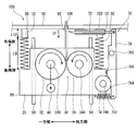
- FIG. 1 is a schematic external view of a band tensioning device 100 according to an embodiment that pulls a band portion 92 of a binding band 90.
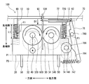
- FIG. It is a schematic plan view which shows the principal part of the band tension
- FIG. It is a schematic plan view which shows the principal part of the band tension
- FIG. 1 is a schematic external view of a band tensioning device 100 according to an embodiment that pulls a band portion 92 of a binding band 90.
- FIG.2 and FIG.3 is a schematic plan view which shows the principal part of the band tension
- FIG. 2 shows a state where the band portion 92 starts to be pulled, and
- FIG. 3 shows a state immediately after the band portion 92 is cut.
- the binding band 90 is wound around a linear member such as a wire harness 900 mounted on a vehicle such as an automobile.
- the wire harness 900 includes, for example, a plurality of electric wires. Each electric wire is a wiring material for electrically interconnecting various electric devices.
- the wire harness 900 may include a linear object other than an electric wire such as an optical cable.
- the binding band 90 includes a band portion 92 and a band fixing portion 94.
- the band portion 92 is formed in a band shape, and the base end portion is connected to the band fixing portion 94.
- a plurality of protrusions are provided on the surface of the band portion 92 along the longitudinal direction.
- the band fixing part 94 has a through hole through which the band part 92 is inserted. Locking claws that lock the plurality of protrusions of the band portion 92 are formed inside the through hole. The band portion 92 inserted through the through-hole of the band fixing portion 94 is locked and fixed by being locked by the locking claws.
- the band pulling device 100 pulls the band portion 92 extending from the band fixing portion 94 and cuts the front end side of the band portion 92.
- the band pulling device 100 may be configured to be used by being held by a hand of an operator, or may be configured to be used in a state where it is installed at a predetermined work position.
- the band tensioning device 100 includes a housing 10, a moving table 20, a band gripping unit 30, a rotation driving unit 40, a pair of guide rails 50 and 50, a pair of elastic members 60 and 60, and a cutting unit 70.
- the housing 10 is a hollow member made of resin or the like, and houses each component of the band tensioning device 100 therein.
- An insertion hole 10 ⁇ / b> H for inserting the band portion 92 is formed inside the housing 10 at the end of the housing 10.
- the end of the housing 10 where the insertion hole 10H is formed is the distal end side of the housing 10, and the opposite side is the proximal end side of the housing 10.
- the movable table 20 is provided with the one-side rotating body 32 and the other-side rotating body 34 of the band gripping unit 30, the rotation driving unit 40, and the cutting rotating body 74 of the cutting unit 70.
- a pair of elastic members 60 are connected to the movable table 20.
- the band gripping unit 30 includes a one-side rotating body 32 and the other-side rotating body 34.
- the band gripping unit 30 grips the front end side portion of the band unit 92 inserted into the housing 10 with the one side rotating body 32 and the other side rotating body 34 sandwiched therebetween.
- the one-side rotating body 32 is a roller member that rotates around the rotation shaft 320.
- the one-side rotating body 32 is disposed on one main surface side of the main surfaces on both sides of the band portion 92 inserted into the housing 10, and the outer peripheral surface thereof abuts on one main surface of the band portion 92. .
- the rotary shaft 320 is fixed to the movable table 20 via a rotary bearing (not shown).
- the side on which the one-side rotating body 32 is disposed as viewed from the band portion 92 is defined as one side of the housing 10, and the side on which the other-side rotating body 34 is disposed as viewed from the band portion 92. Is referred to as the other side of the housing 10.
- the one side rotator 32 is connected to a rotation drive unit 40 including a motor and the like.
- the one side rotator 32 receives power from the rotation drive unit 40 and actively rotates around the rotation shaft 320.
- the rotary shaft 320 may be configured to rotate together with the one-side rotary body 32. However, the rotary shaft 320 is fixed to the moving base 20 and cannot be rotated, and only the one-side rotary body 32 is rotated. You may make it rotate around.
- the operation of the rotation drive unit 40 is controlled by an operator performing a predetermined operation on an operation unit (not shown). Specifically, a switch may be provided, and the rotation driving unit 40 may be operated and stopped by an operator turning on and off the switch.
- the other-side rotating body 34 is a roller member that rotates around the rotating shaft 340.
- the other side rotating body 34 is arranged on the side of the other main surface opposite to the one main surface in the band portion 92, and the outer peripheral surface thereof is in contact with the other main surface of the band portion 92 inserted into the housing 10. Touch.
- the other side rotator 34 is a free roller that rotates passively.
- the other side rotating body 34 may actively rotate so as to synchronize with the rotation of the one side rotating body 32 by connecting a rotation driving unit to the other side rotating body 34.
- the radius of the other side rotating body 34 may be the same as or different from the radius of the one side rotating body 32.
- a plurality of protrusions are formed on the outer peripheral surfaces of the one side rotating body 32 and the other side rotating body 34 along the circumferential direction. For this reason, the leading ends of the protrusions are in contact with both main surfaces of the band portion 92. As a result, the contact area between the band portion 92 and the one-side rotating body 32 and between the band portion 92 and the other-side rotating body 34 can be reduced. Thus, the band portion 92 can be firmly grasped.
- the one side rotary body 32 and the other side rotary body 34 are formed with a plurality of protrusions, and may be omitted.
- the movable table 20 is connected to a pair of guide rails 50 fixed to the housing 10, and can reciprocate along a predetermined path along the extending direction of the pair of guide rails 50.
- the movable table 20 reciprocates on the prescribed route between the initial position P0 shown in FIG. 2 and the cutting position P1 shown in FIG.
- the band gripping unit 30, the rotation drive unit 40, and the cutting rotator 74 also reciprocate integrally in the extending direction of the guide rail 50.
- the extending direction of the pair of guide rails 50 is parallel to the direction in which the band gripping portion 30 pulls the band portion 92.
- the pair of guide rails 50 guide the movable table 20 so as to be movable along a direction (tensile direction D1) in which the band portion 92 inserted into the housing 10 is pulled. Accordingly, the pair of guide rails 50 guide the one-side rotating body 32 of the band gripping part 30 so as to be movable on a prescribed path along the direction in which the band part 92 is pulled.
- the pair of guide rails is an example of a guide portion.
- ⁇ Elastic member 60> One end of each of the pair of elastic members 60, 60 is fixed to a part of the front end side of the housing 10 via the connecting portion 12.
- the one-side rotating body 32 installed on the moving table 20 moves relative to the housing 10.
- the part of the housing 10 to which one end of the pair of elastic members 60, 60 is attached is a position fixed relative to the one-side rotating body 32.
- the other ends of the pair of elastic members 60, 60 are fixed to a surface of the movable table 20 facing the front end side of the housing 10.
- One of the pair of elastic members 60, 60 is disposed on the one main surface side of the band portion 92, and the other is disposed on the other main surface side of the band portion 92.
- the pair of elastic members 60, 60 has a natural length L0. Then, as shown in FIGS. 2 and 3, the movable base 20 moves to the distal end side of the housing 10, thereby compressing the pair of elastic members 60 and 60. That is, the pair of elastic members 60 and 60 urge the movable base 20 toward the base end side of the housing 10.
- the cutting part 70 is a part that cuts the band part 92 inserted into the casing 10 of the band pulling apparatus 100.
- the cutting unit 70 includes a cutting blade 72, a cutting rotating body 74, and a cam 76.
- the cutting blade 72 is arranged inside the housing 10 and at a position closer to the tip side of the housing 10 than the band grip portion 30.
- the cutting rotator 74 cuts the band portion 92 at a portion closer to the base end side than the portion gripped by the band gripping portion 30 in the band portion 92.
- the cutting blade 72 is arranged to extend in a direction orthogonal to the pulling direction D1.
- the cutting blade 72 is translated along a direction orthogonal to the pulling direction D1 by a cutting guide portion 720 fixed to the housing 10.
- the cutting rotator 74 is a roller member that rotates around the rotation shaft 740.
- the rotation shaft 740 is attached to the moving table 20 so that the center thereof stands upright with respect to the moving table 20.
- the outer peripheral surface of the cutting rotating body 74 is in contact with the outer peripheral surface of the cam 76.
- the cam 76 is a plate cam that converts the rotational motion of the cutting rotor 74 into the swing movement of the cutting blade 72.
- the cam 76 extends in the pulling direction D1 as a whole, and is rotatable about a rotation shaft 760 connected to an intermediate portion of the cam 76 (here, an intermediate portion of the cam 76 near the front end of the housing 10). Is provided. A base end portion of the rotation shaft 760 is fixed to the housing 10.
- the portion near the tip of the housing 10 in the cam 76 is connected in a state where the base end of the cutting blade 72 is rotatable. Further, a portion of the cam 76 near the base end of the housing 10 is connected to an elastic member 762 whose one end is fixed to the housing 10.
- the elastic member 762 is a member that urges the cam 76 in a direction to return the cam 76 to the predetermined posture shown in FIG.
- the outer peripheral surface of the cam 76 with which the outer peripheral surface of the cutting rotating body 74 abuts includes a parallel surface 764 and a convex surface 766.
- the parallel surface 764 is parallel to the pulling direction D ⁇ b> 1, and the convex surface 766 protrudes to one side of the housing 10 from the parallel surface 764.
- the distal end portion of the band portion 92 is inserted into the housing 10 through the insertion hole 10H.
- This work is performed, for example, by the operator holding the band fixing part 94, the wire harness 900, or the band part 92 itself.
- the band portion 92 is inserted into the housing 10 until the tip end portion of the band portion 92 reaches a position sandwiched between the one side rotating body 32 and the other side rotating body 34 of the band gripping portion 30.
- the one-side rotating body 32 is rotated by driving the rotation driving unit 40, so that the band unit 92 is drawn between the one-side rotating body 32 and the other-side rotating body 34. That is, the band gripping part 30 grips the band part 92 and starts pulling.
- the band portion 92 is pulled and is in a tension state
- the one-side rotating body 32 starts moving along the band portion 92 toward the distal end side of the housing 10 (the direction opposite to the pulling direction D1).
- the moving base 20 starts moving from the initial position P0 toward the cutting position P1 on the front end side of the housing 10.
- the cutting rotator 74 also moves toward the front end side of the housing 10. Further, as the moving table 20 moves, the pair of elastic members 60, 60 are gradually shortened from the natural length L0. For this reason, the urging
- the tensile force when the band gripping portion 30 pulls the band portion 92 is a force that antagonizes this urging force. For this reason, as the biasing force increases, the tensile force of the band gripping portion 30 also increases.
- the movable table 20 reaches the cutting position P1.
- the cutting rotator 74 comes into contact with the top of the convex surface 766, so that the cam 76 is rotationally displaced, and the cutting blade 72 moves in parallel to one side of the housing 10 to cut the band portion 92.
- the tension of the band portion 92 by the band gripping portion 30 is released. That is, the cutting part 70 constitutes a tension suppression mechanism that suppresses an increase in the tensile force of the band gripping part 30 that pulls the band part 92.
- the movable table 20 is returned from the cutting position P1 to the initial position P0.
- the band gripping portion 30 moves to the initial position shown in FIG. 2 while gripping the surplus portion 920 of the band portion 92 separated from the binding band 90.
- the surplus portion 920 moves between the one-side rotator 32 and the other-side rotator 34 toward the base end side of the housing 10, and from these gaps Get out.
- the surplus portion 920 that has slipped out of the gap is appropriately discharged from the inside of the housing 10 to the outside on the base end side of the housing 10 with respect to the band grip portion 30 by a discharge mechanism (not shown).
- the pair of elastic members 60, 60 also return to the natural length L0, so that the movable table 20 returns to the initial position P0.
- the band gripping unit 30, the rotation driving unit 40 and the cutting rotating body 74 installed on the movable table 20 also return to the initial positions.
- the cam 76 of the cutting portion 70 also returns to the specified posture shown in FIG.
- ⁇ About maximum tensile force> As shown in FIG. 3, the tensile force with which the band gripping portion 30 pulls the band portion 92 is maximized immediately before the band portion 92 is cut.
- the maximum tensile force (maximum tensile force) is substantially equal to “2 ⁇ F1”, which is the total value of the elastic forces F1 of the pair of elastic members 60 and 60 that have reached the specified length L1. That is, in the band tension device 100, it is possible to suppress the band portion 92 from being pulled with a tensile force exceeding “2 ⁇ F1”.
- the tension suppressing mechanism is not limited to the cutting part 70.
- the tension suppressing mechanism instead of the cutting unit 70, the tension suppressing mechanism detects whether or not the elastic member 60 has reached the specified length L1, and drives the rotation driving unit 40 based on the detection result of the detection sensor. It can be configured with a control unit to be stopped. Since the rotation of the one-side rotator 32 is stopped by stopping the driving of the rotation driving unit 40, an increase in the tensile force of the band gripping unit 30 can be suppressed.
- the one-side rotating body 32 may have a function of suppressing reverse rotation, but is not essential.
- the maximum tensile force may be changed by changing the length L12 in the tensile direction of the portion of the casing 10 (the connecting portion 12) to which one end of the elastic member 60 is connected.
- the initial position P0 of the moving base 20 is displaced toward the base end side of the housing 10.
- the initial position of the cutting rotating body 74 with respect to the cam 76 is also relatively displaced to a position near the base end of the housing 10 in the cam 76, so that the distance to the convex surface 766 of the cam 76 becomes larger.
- the specified length L1 of the pair of elastic members 60, 60 when the cutting blade 72 of the cutting unit 70 is operated becomes shorter.
- the maximum tensile force of the band holding part 30 can be increased. Conversely, when weakening the maximum tensile force, the connecting portion 12 may be shortened. Thus, the maximum tensile force of the band holding part 30 can be adjusted by making the length of the connecting part 12 in the pulling direction D1 changeable.
- the pair of elastic members 60, 60 can be replaced with a single elastic member or three or more elastic members.
- the pair of elastic members 60, 60 are arranged so as to extend in parallel with the pulling direction D1 and contract. However, it may be arranged so as to extend and contract in a direction that intersects the tensile direction D1 except for orthogonality.
- the movable table 20 is urged by the elastic force generated by contracting the pair of elastic members 60 and 60.
- the movable table 20 may be urged by an elastic force generated by extending the pair of elastic members 60 and 60.
- the elastic member 60 is extended from the natural length L ⁇ b> 0 by moving the movable base 20 toward the distal end side of the housing 10.
- the elastic member 60 can bias the movable table 20 toward the base end side of the housing 10.
- the other-side rotating body 34 is adopted as the other-side contact portion, but the present invention is not limited to this.
- the other side contact portion may be a member that is in sliding contact with the other main surface of the band portion 92. In this case, it is not essential to install the other-side contact portion on the movable table 20, and the other side contact portion may be fixed to the housing 10.
- the other-side abutting portion is in sliding contact with the band portion 92, the frictional force in the direction that prevents the tensile force is increased, which may affect the tension of the band portion 92. For this reason, since generation
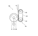
- FIG. 4 is a schematic plan view of a band holding part 30a of a modification.
- the band gripping portion 30a includes a one-side rotating body 32 and the other-side contact portion 34a.
- the other-side contact portion 34a includes a plurality of (here, two) roller portions 342 and 342 and an endless belt 344 spanned between the pair of roller portions 342 and 342.
- the plurality of roller portions 342 and 342 may be passively rotating free rollers, or the motor may be rotated so that one or both of them is actively rotated in synchronization with the rotation of the one-side rotating body 32. It may be connected.
- the band portion 92 can be gripped between the outer peripheral surface of the one side rotating body 32 and the linearly extending portion of the endless belt 344.
- the other side contact portion 34 a is installed on the movable table 20, and it may be fixed to the housing 10.
- the one-side rotating body 32 can also be constituted by two or more roller portions and an endless belt, similarly to the other-side contact portion 34a.
Landscapes
- Engineering & Computer Science (AREA)
- Mechanical Engineering (AREA)
- Basic Packing Technique (AREA)
Abstract
結束バンドのバンド部を引張する際の作業負担を軽減する。バンド引張装置100は、結束バンド90の帯状のバンド部92を引張する装置である。バンド引張装置100は、回転軸320周りに回転可能であるとともに外周面がバンド部92の一方主面に当接する一方側回転体32、及び、バンド部92の他方主面に当接する他方側回転体34を含むバンド把持部30を備える。バンド把持部30は、一方側回転体32及び他方側回転体34の間でバンド部92を挟んで把持する。また、バンド引張装置100は、一方側回転体32を回転させる回転駆動部40と、バンド把持部30の一方側回転体32を引張方向D1に沿って移動可能に案内する一対のガイドレール50,50と、一方側回転体32を、引張方向D1に付勢する一対の弾性部材60,60と、一対の弾性部材60,60が既定長L1に達すると、バンド部92を切断する切断部70を備える。
Description
この発明は、バンド引張装置に関する。
特許文献1には、結束バンドにおけるバンド尾部を緊張させて、バンド尾部をバンド頭部から切断する手持式のツールが開示されている。このツールは、ツール先端のバンド把持爪でバンドを把持し、操作者がトリガーを引く動作を複数回行うことで、バンド尾部が引き締められる。そしてバンド尾部にかかる張力が、あらかじめ設定されたレベルに達すると、バンド尾部を切断するように構成されている。
引用文献1のツールの場合、バンド尾部を引張する操作を手動で行う必要がある。このため、作業者の負担が著しく大きいという問題があった。操作回数が増大するに比例して、作業者の負担も増大してしまうため、改善が求められていた。
そこで、本発明は、結束バンドにおけるバンド部を引張する際の作業負担を軽減する技術を提供することを目的とする。
第1態様は、結束バンドにおける帯状のバンド部を引張するバンド引張装置であって、回転軸周りに回転可能であるとともに外周面が前記バンド部の一方主面に当接する一方側回転体、及び、前記バンド部の他方主面に当接する他方側当接部を含み、前記一方側回転体及び前記他方側当接部の間で前記バンド部を挟んで把持するバンド把持部と、前記一方側回転体を回転させる回転駆動部と、前記バンド把持部の前記一方側回転体を、前記バンド部を引張させる方向に沿って移動可能に案内するガイド部と、前記バンド把持部の前記一方側回転体を、前記バンド部を引張させる方向に付勢する弾性部材と、前記弾性部材が既定長に達すると、前記バンド部を引張する前記バンド把持部の引張力の増加を抑制する引張抑制機構とを備える。
第2態様は、第1態様のバンド引張装置であって、前記一方側回転体の前記外周面には、前記一方側回転体の周方向に沿って複数の突部が形成されている。
第3態様は、第1態様又は第2態様のバンド引張装置であって、前記他方側当接部は、外周面が前記バンド部の前記他方主面に当接する他方側回転体を含む。
第4態様は、第1態様から第3態様のいずれか1つのバンド引張装置であって、前記引張抑制機構は、前記バンド部における前記バンド把持部に保持される部分よりも基端側の位置で前記バンド部を切断する切断部、を含む。
第5態様は、第4態様のバンド引張装置であって、前記切断部は、前記バンド部を切断する切断刃と、前記バンド把持部とともに移動する回転軸周りに回転可能な切断用回転体と前記切断刃に連結されており、前記切断用回転体の回転運動を前記切断刃の揺動移動に変換するカムと、を含む。
第6態様は、第5態様のバンド引張装置であって、前記バンド把持部、前記回転駆動部及び前記切断用回転体が取付けられているとともに、前記弾性部材が接続されている移動台、をさらに備え、前記ガイド部は、前記移動台を、前記バンド部を引張させる方向に沿って移動可能に案内する。
第1態様のバンド引張装置によると、回転駆動部が一方側回転体を回転させることによって、バンド部を自動で引張できるため、作業者の負担を軽減できる。また、弾性部材が規定長に達した際に、バンド把持部がバンド部に及ぼす引張力の増加が抑制される。このため、バンド把持部が規定値を越える引張力でバンド部を引張することを抑制できる。これによって、バンド部の引張を好適に行える。
第2態様のバンド引張装置によると、一方側回転体の外周面に複数の突部を設けることによって、その突部の先端がバンド部に当接される。このため、バンド部と一方側回転体との間の接触面積を小さくすることができるため、相手側当接部材との間でバンド部を強固につかむことができる。
第3態様のバンド引張装置によると、バンド部を回転駆動部によって回転可能な一方側回転体とともに他方側回転体で挟むことができる。したがって、バンド把持部とバンド部の他方主面との間で引張方向とは逆の方向に摩擦力が働くことを低減できるため、バンド部を良好に引張できる。
第4態様のバンド引張装置によると、バンド部のバンド把持部に保持される部分よりも基端側の位置でバンド部を切断することによって、バンド把持部によるバンド部の引張を解除できる。
第5態様のバンド引張装置によると、バンド把持部の移動に連動させて切断刃を揺動移動させてバンド部を切断できる。このように、カム機構を用いることによって、規定値を超える引張力がバンド部にかかることを抑制できるとともに、バンド部の余剰の部分の切断もおこなうことができる。
第6態様のバンド引張装置によると、移動台に、バンド把持部、回転駆動部及び切断用回転体を設置することで、これらを一体的に移動させることができる。
以下、添付の図面を参照しながら、本発明の実施形態について説明する。なお、この実施形態に記載されている構成要素はあくまでも例示であり、本発明の範囲をそれらのみに限定する趣旨のものではない。また、図面においては、理解容易のため、必要に応じて各部の寸法や数が誇張または簡略化して図示されている場合がある。
<1. 実施形態>
図1は、結束バンド90のバンド部92を引張する実施形態のバンド引張装置100の概略外観図である。図2及び図3は、実施形態のバンド引張装置100の主要部を示す概略平面図である。図2はバンド部92が引張され始める状態を示しており、図3はバンド部92が切断された直後の状態を示す図である。
図1は、結束バンド90のバンド部92を引張する実施形態のバンド引張装置100の概略外観図である。図2及び図3は、実施形態のバンド引張装置100の主要部を示す概略平面図である。図2はバンド部92が引張され始める状態を示しており、図3はバンド部92が切断された直後の状態を示す図である。
結束バンド90は、例えば、自動車などの車両に搭載されるワイヤーハーネス900などの線状部材に巻きつけられる。ワイヤーハーネス900は、例えば、複数の電線を含む。各電線は、各種の電気機器同士を電気的に相互接続する配線材である。ワイヤーハーネス900は光ケーブルなどの電線以外の線状物を含んでいてもよい。
結束バンド90は、バンド部92及びバンド固定部94を備える。バンド部92は帯状に形成されており、基端部がバンド固定部94に連結されている。バンド部92の表面には複数の突部が長手方向に沿って設けられている。
バンド固定部94は、バンド部92が挿通される貫通孔が形成されている。この貫通孔の内側には、バンド部92の上記複数の突部を係止する係止爪が形成されている。バンド固定部94の貫通孔に挿通されたバンド部92は、この係止爪に係止されることで、抜け止め固定される。
バンド引張装置100は、バンド固定部94から延び出たバンド部92を引張するとともに、バンド部92の先端側を切断する。バンド引張装置100は、作業者が手で持って使用されるように構成されていてもよいし、あるいは、所定の作業位置に据え置かれた状態で使用されるように構成されていてもよい。
バンド引張装置100は、筐体10、移動台20、バンド把持部30、回転駆動部40、一対のガイドレール50,50、一対の弾性部材60,60及び切断部70を備える。
<筐体10>
筐体10は樹脂などで形成された中空部材であり、その内部にバンド引張装置100の各構成要素を収容している。筐体10の端部には、筐体10の内側にバンド部92を挿通するための挿通孔10Hが形成されている。以下の説明では、筐体10における挿通孔10Hが形成されている側の端部側を筐体10の先端側とし、その反対側を筐体10の基端側とする。
筐体10は樹脂などで形成された中空部材であり、その内部にバンド引張装置100の各構成要素を収容している。筐体10の端部には、筐体10の内側にバンド部92を挿通するための挿通孔10Hが形成されている。以下の説明では、筐体10における挿通孔10Hが形成されている側の端部側を筐体10の先端側とし、その反対側を筐体10の基端側とする。
<移動台20>
移動台20は、バンド把持部30の一方側回転体32及び他方側回転体34、回転駆動部40及び切断部70の切断用回転体74が取付けられている。移動台20には、一対の弾性部材60が接続されている。
移動台20は、バンド把持部30の一方側回転体32及び他方側回転体34、回転駆動部40及び切断部70の切断用回転体74が取付けられている。移動台20には、一対の弾性部材60が接続されている。
<バンド把持部30>
バンド把持部30は、一方側回転体32及び他方側回転体34を備える。バンド把持部30は、筐体10に挿入されたバンド部92の先端側部分を一方側回転体32及び他方側回転体34で挟み込んで把持する。
バンド把持部30は、一方側回転体32及び他方側回転体34を備える。バンド把持部30は、筐体10に挿入されたバンド部92の先端側部分を一方側回転体32及び他方側回転体34で挟み込んで把持する。
一方側回転体32は、回転軸320周りに回転するローラ部材である。一方側回転体32は、筐体10に挿入されたバンド部92の両側の主面のうちの一方主面の側に配されており、その外周面がバンド部92の一方主面に当接する。回転軸320は不図示の回転軸受などを介して移動台20に固定されている。
なお、以下の説明では、バンド部92から見て一方側回転体32が配されている側を筐体10の一方側とし、バンド部92から見て他方側回転体34が配されている側を筐体10の他方側と称する。
一方側回転体32は、モータなどを含む回転駆動部40に接続されている。一方側回転体32は、回転駆動部40から動力を受けて回転軸320周りに能動的に回転する。なお、回転軸320が一方側回転体32とともに回転するように構成されてもよいが、回転軸320が移動台20に固定されて回転不能とされて、一方側回転体32のみが回転軸320周りに回転するようにしてもよい。
回転駆動部40は、不図示の操作部に対して作業者が所定操作を行うことで、その動作が制御される。具体的には、スイッチを設けて、作業者がそのスイッチをオンオフ操作することで、回転駆動部40が作動及び停止が行われるようにしてもよい。
他方側回転体34は、回転軸340周りに回転するローラ部材である。他方側回転体34は、バンド部92における一方主面とは反対側の他方主面の側に配されており、その外周面が筐体10に挿入されたバンド部92の他方主面に当接する。他方側回転体34は受動的に回転するフリーローラとされている。なお、他方側回転体34に回転駆動部を接続することで、一方側回転体32の回転と同期するように他方側回転体34が能動的に回転してもよい。他方側回転体34の半径は、一方側回転体32の半径と同一でもよいし、異なっていてもよい。
一方側回転体32及び他方側回転体34の外周面には、その周方向に沿って複数の突部が形成されている。このため、バンド部92の両主面には、各突部の先端が当接する。これによって、バンド部92及び一方側回転体32、並びに、バンド部92及び他方側回転体34の間の接触面積を小さくすることができるため、一方側回転体32及び他方側回転体34の間でバンド部92を強固につかむことができる。なお、一方側回転体32及び他方側回転体34に複数の突部が形成されていることは必須ではなく、省略することも可能である。
<ガイドレール50>
移動台20は、筐体10に固定された一対のガイドレール50に接続されており、一対のガイドレール50の延在方向に沿って規定の経路上を往復移動可能とされている。ここでは、移動台20は、図2が示す初期位置P0と、図3が示す切断位置P1との間で規定経路上を往復移動する。この移動台20の往復移動に伴って、バンド把持部30、回転駆動部40及び切断用回転体74も、ガイドレール50の延在方向に一体的に往復移動する。一対のガイドレール50の延在方向は、バンド把持部30がバンド部92を引張する方向と平行となっている。一対のガイドレール50は、移動台20を、筐体10に挿入されたバンド部92を引張させる方向(引張方向D1)沿って移動可能に案内する。したがって、一対のガイドレール50は、バンド把持部30の一方側回転体32を、そのバンド部92を引張させる方向に沿った規定経路上を移動可能に案内する。一対のガイドレールは、ガイド部の一例である。
移動台20は、筐体10に固定された一対のガイドレール50に接続されており、一対のガイドレール50の延在方向に沿って規定の経路上を往復移動可能とされている。ここでは、移動台20は、図2が示す初期位置P0と、図3が示す切断位置P1との間で規定経路上を往復移動する。この移動台20の往復移動に伴って、バンド把持部30、回転駆動部40及び切断用回転体74も、ガイドレール50の延在方向に一体的に往復移動する。一対のガイドレール50の延在方向は、バンド把持部30がバンド部92を引張する方向と平行となっている。一対のガイドレール50は、移動台20を、筐体10に挿入されたバンド部92を引張させる方向(引張方向D1)沿って移動可能に案内する。したがって、一対のガイドレール50は、バンド把持部30の一方側回転体32を、そのバンド部92を引張させる方向に沿った規定経路上を移動可能に案内する。一対のガイドレールは、ガイド部の一例である。
<弾性部材60>
一対の弾性部材60,60の一端のそれぞれは、筐体10の先端側の一部分に対して連結部12を介して固定されている。移動台20に設置された一方側回転体32は、筐体10に対して相対的に移動する。このため、一対の弾性部材60,60の一端が取り付けられている筐体10の部分は、一方側回転体32に対して相対的に固定された位置である。一対の弾性部材60,60の他端は、移動台20における筐体10の先端側を向く面に固定されている。一対の弾性部材60,60のうち、一方はバンド部92の一方主面の側に配されており、他方はバンド部92の他方主面の側に配されている。
一対の弾性部材60,60の一端のそれぞれは、筐体10の先端側の一部分に対して連結部12を介して固定されている。移動台20に設置された一方側回転体32は、筐体10に対して相対的に移動する。このため、一対の弾性部材60,60の一端が取り付けられている筐体10の部分は、一方側回転体32に対して相対的に固定された位置である。一対の弾性部材60,60の他端は、移動台20における筐体10の先端側を向く面に固定されている。一対の弾性部材60,60のうち、一方はバンド部92の一方主面の側に配されており、他方はバンド部92の他方主面の側に配されている。
図2が示すように、バンド把持部30がバンド部92を把持する直前は、一対の弾性部材60,60が自然長L0とされている。そして、図2及び図3が示すように、移動台20が筐体10の先端側へ移動することで、一対の弾性部材60,60が圧縮される。つまり、一対の弾性部材60,60は、移動台20を筐体10の基端側へ付勢する。
<切断部70>
切断部70は、バンド引張装置100の筐体10に挿入されたバンド部92を切断する部分である。切断部70は、切断刃72、切断用回転体74、カム76を備える。
切断部70は、バンド引張装置100の筐体10に挿入されたバンド部92を切断する部分である。切断部70は、切断刃72、切断用回転体74、カム76を備える。
切断刃72は、筐体10の内側であって、バンド把持部30よりも筐体10の先端側の位置に配されている。切断用回転体74は、バンド部92におけるバンド把持部30で把持される部分よりも基端側の部分でバンド部92を切断する。
切断刃72は、引張方向D1に直交する方向に延びるように配されている。切断刃72は、筐体10に固定された切断ガイド部720によって引張方向D1に直交する方向に沿って平行移動する。
切断用回転体74は、回転軸740を中心に回転するローラ部材である。回転軸740は、その中心が移動台20に対して垂直に起立するように、移動台20に取り付けられている。切断用回転体74の外周面は、カム76の外周面に接している。
カム76は、切断用回転体74の回転運動を切断刃72の揺動移動に変換する板カムである。カム76は、全体として引張方向D1に延びており、カム76の中間部(ここでは、カム76における筐体10の先端寄りの中間部)に連結された回転軸760を中心に回転移動可能に設けられている。回転軸760の基端部は、筐体10に固定されている。
カム76における筐体10の先端寄りの部分は、切断刃72の基端部が回転可能な状態で連結されている。また、カム76における筐体10の基端寄りの部分は、一端が筐体10に固定されている弾性部材762に連結されている。弾性部材762は、カム76を図2に示される既定姿勢に戻す方向に付勢する部材である。
切断用回転体74の外周面が当接するカム76の外周面は、平行面764と凸状面766とを含む。カム76が図2に示される既定姿勢のとき、平行面764は引張方向D1と平行とされ、凸状面766は平行面764よりも筐体10の一方側に突出している。
図2及び図3が示すように、移動台20が筐体10の先端側へ移動すると、切断用回転体74がカム76の平行面764から凸状面766へ向けて相対的に移動する。そして、切断用回転体74の外周面が凸状面766上を移動することで、カム76が回転軸760周りに回転移動する。これによって、カム76の先端側に連結された切断刃72が筐体10の一方側へ平行移動する。このようなカム機構を用いることによって、規定値を超える引張力がバンド部92にかかることを抑制できるとともに、バンド部92の余剰の部分の切断もおこなうことができる。
<バンド引張装置100の動作>
次に、バンド引張装置100が行う引張動作について説明する。ここでは、図1が示すように、結束バンド90のバンド部92が、ワイヤーハーネス900に巻付けられ、バンド固定部94に挿通されているものとする。
次に、バンド引張装置100が行う引張動作について説明する。ここでは、図1が示すように、結束バンド90のバンド部92が、ワイヤーハーネス900に巻付けられ、バンド固定部94に挿通されているものとする。
図1及び図2が示すように、バンド部92の先端部は、挿通孔10Hを通じて筐体10の内側に挿入される。この作業は、例えば作業者が、バンド固定部94、ワイヤーハーネス900又はバンド部92自体を把持して行われる。
そして、バンド部92の先端部が、バンド把持部30の一方側回転体32及び他方側回転体34に挟まれる位置に達するまで、バンド部92が筐体10内に挿入される。
続いて、回転駆動部40の駆動によって、一方側回転体32が回転することで、バンド部92が一方側回転体32及び他方側回転体34の間に引き込まれる。すなわち、バンド把持部30がバンド部92を把持して引張を開始する。バンド部92が引張されて緊張状態となると、一方側回転体32は、バンド部92に沿って、筐体10の先端側(引張方向D1とは反対の方向)に向けて移動を開始する。この一方側回転体32の移動に伴って、移動台20が初期位置P0から筐体10の先端側の切断位置P1に向けて移動を開始する。
移動台20の移動に伴い、切断用回転体74も筐体10の先端側へ向けて移動する。また、移動台20の移動に伴い、一対の弾性部材60,60が自然長L0から徐々に縮められる。このため、移動台20が一対の弾性部材60,60から受ける引張方向D1の付勢力は次第に増加する。バンド把持部30がバンド部92を引張するときの引張力は、この付勢力に拮抗する力である。このため、付勢力が増加するに連れて、バンド把持部30の引張力も増加する。
図3が示すように、一対の弾性部材60,60各々が規定長L1に達したとき、移動台20が切断位置P1に到達する。このとき、切断用回転体74が凸状面766の頂部に当接することでカム76が回転変位し、切断刃72が筐体10の一方側へ平行移動してバンド部92を切断する。これによって、バンド把持部30によるバンド部92の引張が解除される。つまり、切断部70は、バンド部92を引張するバンド把持部30の引張力の増加を抑制する、引張抑制機構を構成している。
バンド部92が切断されると、移動台20が切断位置P1から初期位置P0に戻される。このとき、バンド把持部30は、結束バンド90から切り離されたバンド部92の余剰部分920を把持したまま、図2が示す初期位置へ移動する。そして、一方側回転体32が回転を継続することによって、余剰部分920が一方側回転体32及び他方側回転体34の間を筐体10の基端側へ向けて移動し、これらの隙間から抜け出す。隙間から抜け出した余剰部分920は、図示を省略する排出機構によって、バンド把持部30よりも筐体10の基端側で、筐体10の内側から外側へ適宜排出される。
移動台20が切断位置P1から初期位置P0へ向けて移動するのに伴い、切断用回転体74が筐体10の基端側へ移動する。これによって、弾性部材742の弾性力でカム76が図2に示される規定姿勢に戻るとともに、切断刃72が筐体10の他方側へ移動する。
以上のようにして、一対の弾性部材60,60も自然長L0に復帰することで、移動台20が初期位置P0に復帰する。これによって、移動台20に設置されたバンド把持部30、回転駆動部40及び切断用回転体74も初期位置に復帰する。また、切断用回転体74が初期位置に復帰することによって、切断部70のカム76も図2が示す規定姿勢へ復帰する。
<最大引張力について>
図3が示すように、バンド把持部30がバンド部92を引張する引張力は、バンド部92が切断される直前で最大となる。この最大となる引張力(最大引張力)は、規定長L1に到達した一対の弾性部材60,60各々の弾性力F1の合計値である「2・F1」に略等しい。すなわち、バンド引張装置100においては、「2・F1」を越える引張力でバンド部92を引張することが抑制される。
図3が示すように、バンド把持部30がバンド部92を引張する引張力は、バンド部92が切断される直前で最大となる。この最大となる引張力(最大引張力)は、規定長L1に到達した一対の弾性部材60,60各々の弾性力F1の合計値である「2・F1」に略等しい。すなわち、バンド引張装置100においては、「2・F1」を越える引張力でバンド部92を引張することが抑制される。
<効果>
以上のように、バンド引張装置100でバンド部92の引張を行うことによって、回転駆動部40の駆動により自動でバンド部92の引張を行うことができる。このため、作業者が手動で引張作業を行う場合よりも、大幅に作業負担を軽減できる。また、一対の弾性部材60,60各々が規定長L1に達するまで、それらの変形によって生じる弾性力に拮抗する引張力でバンド把持部30がバンド部92を引張する。そして、一対の弾性部材60,60が規定長L1に達すると、切断部70がバンド部92を切断することによって、バンド把持部30の引張が解除される。すなわち、バンド把持部30の引張力の増加が抑制される。したがって、バンド把持部30が規定値(=2・F1)を越える引張力でバンド部92を引張することを抑制できるため、バンド部92の引張を適切に行うことができる。これによって、ワイヤーハーネス900などの締付対象物を適度な力で締付けることができる。
以上のように、バンド引張装置100でバンド部92の引張を行うことによって、回転駆動部40の駆動により自動でバンド部92の引張を行うことができる。このため、作業者が手動で引張作業を行う場合よりも、大幅に作業負担を軽減できる。また、一対の弾性部材60,60各々が規定長L1に達するまで、それらの変形によって生じる弾性力に拮抗する引張力でバンド把持部30がバンド部92を引張する。そして、一対の弾性部材60,60が規定長L1に達すると、切断部70がバンド部92を切断することによって、バンド把持部30の引張が解除される。すなわち、バンド把持部30の引張力の増加が抑制される。したがって、バンド把持部30が規定値(=2・F1)を越える引張力でバンド部92を引張することを抑制できるため、バンド部92の引張を適切に行うことができる。これによって、ワイヤーハーネス900などの締付対象物を適度な力で締付けることができる。
<2. 変形例>
以上、実施形態について説明してきたが、本発明は上記のようなものに限定されるものではなく、様々な変形が可能である。
以上、実施形態について説明してきたが、本発明は上記のようなものに限定されるものではなく、様々な変形が可能である。
例えば、引張抑制機構は、切断部70に限定されるものではない。例えば、引張抑制機構は、切断部70の代わりとして、弾性部材60が規定長L1に達したかどうかを検出する検出センサー、及び、その検出センサーの検出結果に基づいて回転駆動部40の駆動を停止させる制御部とで構成可能である。回転駆動部40の駆動が停止されることで、一方側回転体32の回転が停止されるため、バンド把持部30の引張力が増加することを抑制できる。この変形例の場合、一方側回転体32が、逆回転することを抑制する機能を備えていてもよいが、必須ではない。なぜなら、一方側回転体32が回転力を失った場合でも、バンド部92がバンド固定部94の内側で抜け止め固定されることで、バンド部92がその基端部側に移動することが抑制されるためである。また、この変形例の場合、切断刃72を、カム76などによって移動台20の移動に連動させなくてよい。このため、切断刃72を別の機構で動作させることが可能である。
上記実施形態において、弾性部材60の一端が接続されている筐体10の部分(連結部12)の引張方向の長さL12を可変とすることで、最大引張力を変更できるようにしてもよい。例えば、長さL12をより長くすることで、移動台20の初期位置P0が筐体10の基端側に変位する。これによって、カム76に対する切断用回転体74の初期位置も、カム76における筐体10の基端寄りの位置へ相対的に変位するため、カム76の凸状面766までの距離がより大きくなる。すると、切断部70の切断刃72が作動する際の、一対の弾性部材60,60の規定長L1がより短くなる。すなわち、バンド把持部30の最大引張力を増大させることができる。逆に、最大引張力を弱める場合には、連結部12を短くすればよい。このように、連結部12の引張方向D1の長さを変更可能にすることによって、バンド把持部30の最大引張力を調整できる。
上記実施形態において、一対の弾性部材60,60を単一の弾性部材又は3つ以上の弾性部材に置き換える事も可能である。
上記実施形態において、一対の弾性部材60,60は、引張方向D1に平行に延び縮みするように配されている。しかしながら、引張方向D1に直交を除いて交差する方向に延び縮みするように配されていてもよい。
上記実施形態では、一対の弾性部材60,60を収縮させることで生じた弾性力で移動台20を付勢している。しかしながら、一対の弾性部材60,60を伸張させることで生じる弾性力で移動台20を付勢してもよい。例えば、一対の弾性部材60,60の両端のうち、一端を筐体10の基端側の部分に取り付け、他端を移動台20における筐体10の基端側を向く面に取り付けることが考えられる。この場合、移動台20が筐体10の先端側へ移動することで弾性部材60が自然長L0から引き延ばされる。これによって、弾性部材60が移動台20を筐体10の基端側へ付勢できる。
上記実施形態では、他方側当接部として他方側回転体34が採用されているが、これに限定されるものではない。例えば、他方側当接部をバンド部92の他方主面と摺接する部材としてもよい。また、この場合、他方側当接部を移動台20に設置することは必須ではなく、筐体10に固定されていてもよい。ただし、他方側当接部がバンド部92に摺接する場合、引張力を妨げる方向の摩擦力が大きくなり、バンド部92の引張に影響するおそれがある。このため、他方側当接部を他方側回転体34とすることによって、このような摩擦力の発生を低減できるため、バンド部92の引張を良好に行える。
他方側当接部は、他方側回転体34のようにローラ部材であることは必須ではない。図4は、変形例のバンド把持部30aの概略平面図である。このバンド把持部30aは、一方側回転体32及び他方側当接部34aを備えている。他方側当接部34aは、複数(ここでは2つ)ローラ部342,342と、その一対のローラ部342,342に架け渡された無端ベルト344とで構成されている。複数のローラ部342,342は、受動的に回転するフリーローラとされていてもよいし、どちらか一方または両方が一方側回転体32の回転と同期して能動的に回転するようにモータが接続されていてもよい。この他方側当接部34aの場合、一方側回転体32の外周面と、無端ベルト344における直線状に延びる部分との間でバンド部92を把持することができる。なお、他方側当接部34aは、移動台20に設置されていることは必須ではなく、筐体10に固定されていてもよい。また、一方側回転体32についても、他方側当接部34aと同様に、2つ以上のローラ部と無端ベルトとで構成することも可能である。
この発明は詳細に説明されたが、上記の説明は、すべての局面において、例示であって、この発明がそれに限定されるものではない。例示されていない無数の変形例が、この発明の範囲から外れることなく想定され得るものと解される。また、上記各実施形態及び各変形例で説明した各構成は、相互に矛盾しない限り適宜組み合わせたり、省略したりすることができる。
100 バンド引張装置
10 筐体
10H 挿通孔
20 移動台
30,30a バンド把持部
32 一方側回転体
34 他方側回転体(他方側当接部)
34a 他方側当接部
342 ローラ部
344 無端ベルト
40 回転駆動部
50 ガイドレール(ガイド部)
60 弾性部材
70 切断部
72 切断刃
74 切断用回転体
76 カム
90 結束バンド
92 バンド部
94 バンド固定部
320 回転軸
720 切断ガイド部
740 回転軸
742 弾性部材
760 回転軸
762 弾性部材
900 ワイヤーハーネス
920 余剰部分
D1 引張方向
L0 自然長
L1 規定長
P0 初期位置
P1 切断位置
10 筐体
10H 挿通孔
20 移動台
30,30a バンド把持部
32 一方側回転体
34 他方側回転体(他方側当接部)
34a 他方側当接部
342 ローラ部
344 無端ベルト
40 回転駆動部
50 ガイドレール(ガイド部)
60 弾性部材
70 切断部
72 切断刃
74 切断用回転体
76 カム
90 結束バンド
92 バンド部
94 バンド固定部
320 回転軸
720 切断ガイド部
740 回転軸
742 弾性部材
760 回転軸
762 弾性部材
900 ワイヤーハーネス
920 余剰部分
D1 引張方向
L0 自然長
L1 規定長
P0 初期位置
P1 切断位置
Claims (6)
- 結束バンドにおける帯状のバンド部を引張するバンド引張装置であって、
回転軸周りに回転可能であるとともに外周面が前記バンド部の一方主面に当接する一方側回転体、及び、前記バンド部の他方主面に当接する他方側当接部を含み、前記一方側回転体及び前記他方側当接部の間で前記バンド部を挟んで把持するバンド把持部と、
前記一方側回転体を回転させる回転駆動部と、
前記バンド把持部の前記一方側回転体を、前記バンド部を引張させる方向に沿って移動可能に案内するガイド部と、
前記バンド把持部の前記一方側回転体を、前記バンド部を引張させる方向に付勢する弾性部材と、
前記弾性部材が既定長に達すると、前記バンド部を引張する前記バンド把持部の引張力の増加を抑制する引張抑制機構と、
を備える、バンド引張装置。 - 請求項1のバンド引張装置であって、
前記一方側回転体の前記外周面には、前記一方側回転体の周方向に沿って複数の突部が形成されている、バンド引張装置。 - 請求項1又は請求項2のバンド引張装置であって、
前記他方側当接部は、外周面が前記バンド部の前記他方主面に当接する他方側回転体を含む、バンド引張装置。 - 請求項1から請求項3のいずれか1項のバンド引張装置であって、
前記引張抑制機構は、前記バンド部における前記バンド把持部に保持される部分よりも基端側の位置で前記バンド部を切断する切断部、を含む、バンド引張装置。 - 請求項4のバンド引張装置であって、
前記切断部は、
前記バンド部を切断する切断刃と、
前記バンド把持部とともに移動する回転軸周りに回転可能な切断用回転体と
前記切断刃に連結されており、前記切断用回転体の回転運動を前記切断刃の揺動移動に変換するカムと、
を含む、バンド引張装置。 - 請求項5のバンド引張装置であって、
前記バンド把持部、前記回転駆動部及び前記切断用回転体が取付けられているとともに、前記弾性部材が接続されている移動台、
をさらに備え、
前記ガイド部は、前記移動台を、前記バンド部を引張させる方向に沿って移動可能に案内する、バンド引張装置。
Applications Claiming Priority (2)
| Application Number | Priority Date | Filing Date | Title |
|---|---|---|---|
| JP2016093104A JP2017200831A (ja) | 2016-05-06 | 2016-05-06 | バンド引張装置 |
| JP2016-093104 | 2016-05-06 |
Publications (1)
| Publication Number | Publication Date |
|---|---|
| WO2017191756A1 true WO2017191756A1 (ja) | 2017-11-09 |
Family
ID=60203023
Family Applications (1)
| Application Number | Title | Priority Date | Filing Date |
|---|---|---|---|
| PCT/JP2017/015702 Ceased WO2017191756A1 (ja) | 2016-05-06 | 2017-04-19 | バンド引張装置 |
Country Status (2)
| Country | Link |
|---|---|
| JP (1) | JP2017200831A (ja) |
| WO (1) | WO2017191756A1 (ja) |
Citations (4)
| Publication number | Priority date | Publication date | Assignee | Title |
|---|---|---|---|---|
| JPH09110010A (ja) * | 1995-10-13 | 1997-04-28 | Taiton Kk | 可搬式電動結束バンド引締め装置 |
| JP2001233304A (ja) * | 2001-02-05 | 2001-08-28 | Amano Corp | 結束方法およびその装置 |
| JP2006248570A (ja) * | 2005-03-10 | 2006-09-21 | Hellermann Tyton Co Ltd | 結束工具の結束位置決め構造及び結束位置決め方法 |
| JP2007238102A (ja) * | 2006-03-06 | 2007-09-20 | Hellermann Tyton Co Ltd | 人為駆動型結束工具 |
-
2016
- 2016-05-06 JP JP2016093104A patent/JP2017200831A/ja active Pending
-
2017
- 2017-04-19 WO PCT/JP2017/015702 patent/WO2017191756A1/ja not_active Ceased
Patent Citations (4)
| Publication number | Priority date | Publication date | Assignee | Title |
|---|---|---|---|---|
| JPH09110010A (ja) * | 1995-10-13 | 1997-04-28 | Taiton Kk | 可搬式電動結束バンド引締め装置 |
| JP2001233304A (ja) * | 2001-02-05 | 2001-08-28 | Amano Corp | 結束方法およびその装置 |
| JP2006248570A (ja) * | 2005-03-10 | 2006-09-21 | Hellermann Tyton Co Ltd | 結束工具の結束位置決め構造及び結束位置決め方法 |
| JP2007238102A (ja) * | 2006-03-06 | 2007-09-20 | Hellermann Tyton Co Ltd | 人為駆動型結束工具 |
Also Published As
| Publication number | Publication date |
|---|---|
| JP2017200831A (ja) | 2017-11-09 |
Similar Documents
| Publication | Publication Date | Title |
|---|---|---|
| JP2021526875A5 (ja) | ||
| CN108454928B (zh) | 捆扎机 | |
| WO2016017597A1 (ja) | 処置具駆動装置 | |
| ATE485135T1 (de) | Roboterstruktur vom scara-typ und entsprechender roboter | |
| JP6029561B2 (ja) | 把持装置 | |
| KR102184066B1 (ko) | 핸드 기구 | |
| WO2013037075A3 (fr) | Dispositif tire-fil pour le câblage électrique | |
| WO2010111801A3 (fr) | Dispositif tire-fil pour le cablage electrique | |
| KR102032374B1 (ko) | 로봇 관절 구동 장치 및 이를 포함하는 로봇 | |
| WO2017191756A1 (ja) | バンド引張装置 | |
| CN110949279A (zh) | 扁平电缆卷绕装置和扁平电缆布设结构 | |
| JP5573892B2 (ja) | 電動ハンド | |
| US9335114B2 (en) | Self-tunable compound bow | |
| WO2018074266A1 (ja) | テープ巻付装置 | |
| EP2604395A3 (en) | Electric supply cable sheath for a power tool | |
| KR100968294B1 (ko) | 권취장치 | |
| US9333575B2 (en) | Wire electric discharge machine and wire electrode removal device | |
| KR102251348B1 (ko) | 착용식 로봇의 구동 모듈 | |
| JP5942870B2 (ja) | 電線搬送装置及び電線処理装置 | |
| FI100790B (fi) | Sovitelma puolaajan yhteydessä | |
| JP2013049129A5 (ja) | ||
| JP2010105125A (ja) | 電動ハンド | |
| JP6014296B2 (ja) | 手持ち動力工具 | |
| JP2016046947A (ja) | 防護管挿入器 | |
| JP4317891B2 (ja) | テープカッター及びカット装置 |
Legal Events
| Date | Code | Title | Description |
|---|---|---|---|
| NENP | Non-entry into the national phase |
Ref country code: DE |
|
| 121 | Ep: the epo has been informed by wipo that ep was designated in this application |
Ref document number: 17792689 Country of ref document: EP Kind code of ref document: A1 |
|
| 122 | Ep: pct application non-entry in european phase |
Ref document number: 17792689 Country of ref document: EP Kind code of ref document: A1 |