WO2017191776A1 - Procédé de fabrication de film conducteur anisotrope et film conducteur anisotrope - Google Patents
Procédé de fabrication de film conducteur anisotrope et film conducteur anisotrope Download PDFInfo
- Publication number
- WO2017191776A1 WO2017191776A1 PCT/JP2017/016255 JP2017016255W WO2017191776A1 WO 2017191776 A1 WO2017191776 A1 WO 2017191776A1 JP 2017016255 W JP2017016255 W JP 2017016255W WO 2017191776 A1 WO2017191776 A1 WO 2017191776A1
- Authority
- WO
- WIPO (PCT)
- Prior art keywords
- particle size
- conductive particles
- particles
- film
- axis
- Prior art date
- Legal status (The legal status is an assumption and is not a legal conclusion. Google has not performed a legal analysis and makes no representation as to the accuracy of the status listed.)
- Ceased
Links
Images


Classifications
-
- C—CHEMISTRY; METALLURGY
- C08—ORGANIC MACROMOLECULAR COMPOUNDS; THEIR PREPARATION OR CHEMICAL WORKING-UP; COMPOSITIONS BASED THEREON
- C08K—Use of inorganic or non-macromolecular organic substances as compounding ingredients
- C08K9/00—Use of pretreated ingredients
- C08K9/02—Ingredients treated with inorganic substances
-
- H—ELECTRICITY
- H01—ELECTRIC ELEMENTS
- H01B—CABLES; CONDUCTORS; INSULATORS; SELECTION OF MATERIALS FOR THEIR CONDUCTIVE, INSULATING OR DIELECTRIC PROPERTIES
- H01B13/00—Apparatus or processes specially adapted for manufacturing conductors or cables
-
- C—CHEMISTRY; METALLURGY
- C09—DYES; PAINTS; POLISHES; NATURAL RESINS; ADHESIVES; COMPOSITIONS NOT OTHERWISE PROVIDED FOR; APPLICATIONS OF MATERIALS NOT OTHERWISE PROVIDED FOR
- C09J—ADHESIVES; NON-MECHANICAL ASPECTS OF ADHESIVE PROCESSES IN GENERAL; ADHESIVE PROCESSES NOT PROVIDED FOR ELSEWHERE; USE OF MATERIALS AS ADHESIVES
- C09J7/00—Adhesives in the form of films or foils
- C09J7/30—Adhesives in the form of films or foils characterised by the adhesive composition
-
- C—CHEMISTRY; METALLURGY
- C09—DYES; PAINTS; POLISHES; NATURAL RESINS; ADHESIVES; COMPOSITIONS NOT OTHERWISE PROVIDED FOR; APPLICATIONS OF MATERIALS NOT OTHERWISE PROVIDED FOR
- C09J—ADHESIVES; NON-MECHANICAL ASPECTS OF ADHESIVE PROCESSES IN GENERAL; ADHESIVE PROCESSES NOT PROVIDED FOR ELSEWHERE; USE OF MATERIALS AS ADHESIVES
- C09J9/00—Adhesives characterised by their physical nature or the effects produced, e.g. glue sticks
- C09J9/02—Electrically-conducting adhesives
-
- H—ELECTRICITY
- H01—ELECTRIC ELEMENTS
- H01B—CABLES; CONDUCTORS; INSULATORS; SELECTION OF MATERIALS FOR THEIR CONDUCTIVE, INSULATING OR DIELECTRIC PROPERTIES
- H01B1/00—Conductors or conductive bodies characterised by the conductive materials; Selection of materials as conductors
- H01B1/20—Conductive material dispersed in non-conductive organic material
- H01B1/22—Conductive material dispersed in non-conductive organic material the conductive material comprising metals or alloys
-
- H—ELECTRICITY
- H01—ELECTRIC ELEMENTS
- H01B—CABLES; CONDUCTORS; INSULATORS; SELECTION OF MATERIALS FOR THEIR CONDUCTIVE, INSULATING OR DIELECTRIC PROPERTIES
- H01B13/00—Apparatus or processes specially adapted for manufacturing conductors or cables
- H01B13/34—Apparatus or processes specially adapted for manufacturing conductors or cables for marking conductors or cables
-
- H—ELECTRICITY
- H01—ELECTRIC ELEMENTS
- H01B—CABLES; CONDUCTORS; INSULATORS; SELECTION OF MATERIALS FOR THEIR CONDUCTIVE, INSULATING OR DIELECTRIC PROPERTIES
- H01B5/00—Non-insulated conductors or conductive bodies characterised by their form
- H01B5/16—Non-insulated conductors or conductive bodies characterised by their form comprising conductive material in insulating or poorly conductive material, e.g. conductive rubber
-
- H—ELECTRICITY
- H01—ELECTRIC ELEMENTS
- H01R—ELECTRICALLY-CONDUCTIVE CONNECTIONS; STRUCTURAL ASSOCIATIONS OF A PLURALITY OF MUTUALLY-INSULATED ELECTRICAL CONNECTING ELEMENTS; COUPLING DEVICES; CURRENT COLLECTORS
- H01R11/00—Individual connecting elements providing two or more spaced connecting locations for conductive members which are, or may be, thereby interconnected, e.g. end pieces for wires or cables supported by the wire or cable and having means for facilitating electrical connection to some other wire, terminal, or conductive member, blocks of binding posts
- H01R11/01—Individual connecting elements providing two or more spaced connecting locations for conductive members which are, or may be, thereby interconnected, e.g. end pieces for wires or cables supported by the wire or cable and having means for facilitating electrical connection to some other wire, terminal, or conductive member, blocks of binding posts characterised by the form or arrangement of the conductive interconnection between the connecting locations
-
- H—ELECTRICITY
- H01—ELECTRIC ELEMENTS
- H01R—ELECTRICALLY-CONDUCTIVE CONNECTIONS; STRUCTURAL ASSOCIATIONS OF A PLURALITY OF MUTUALLY-INSULATED ELECTRICAL CONNECTING ELEMENTS; COUPLING DEVICES; CURRENT COLLECTORS
- H01R4/00—Electrically-conductive connections between two or more conductive members in direct contact, i.e. touching one another; Means for effecting or maintaining such contact; Electrically-conductive connections having two or more spaced connecting locations for conductors and using contact members penetrating insulation
- H01R4/04—Electrically-conductive connections between two or more conductive members in direct contact, i.e. touching one another; Means for effecting or maintaining such contact; Electrically-conductive connections having two or more spaced connecting locations for conductors and using contact members penetrating insulation using electrically conductive adhesives
-
- H—ELECTRICITY
- H01—ELECTRIC ELEMENTS
- H01R—ELECTRICALLY-CONDUCTIVE CONNECTIONS; STRUCTURAL ASSOCIATIONS OF A PLURALITY OF MUTUALLY-INSULATED ELECTRICAL CONNECTING ELEMENTS; COUPLING DEVICES; CURRENT COLLECTORS
- H01R43/00—Apparatus or processes specially adapted for manufacturing, assembling, maintaining, or repairing of line connectors or current collectors or for joining electric conductors
-
- H—ELECTRICITY
- H10—SEMICONDUCTOR DEVICES; ELECTRIC SOLID-STATE DEVICES NOT OTHERWISE PROVIDED FOR
- H10W—GENERIC PACKAGES, INTERCONNECTIONS, CONNECTORS OR OTHER CONSTRUCTIONAL DETAILS OF DEVICES COVERED BY CLASS H10
- H10W72/00—Interconnections or connectors in packages
- H10W72/071—Connecting or disconnecting
- H10W72/073—Connecting or disconnecting of die-attach connectors
-
- C—CHEMISTRY; METALLURGY
- C08—ORGANIC MACROMOLECULAR COMPOUNDS; THEIR PREPARATION OR CHEMICAL WORKING-UP; COMPOSITIONS BASED THEREON
- C08K—Use of inorganic or non-macromolecular organic substances as compounding ingredients
- C08K3/00—Use of inorganic substances as compounding ingredients
- C08K3/02—Elements
- C08K3/08—Metals
- C08K2003/0806—Silver
-
- C—CHEMISTRY; METALLURGY
- C08—ORGANIC MACROMOLECULAR COMPOUNDS; THEIR PREPARATION OR CHEMICAL WORKING-UP; COMPOSITIONS BASED THEREON
- C08K—Use of inorganic or non-macromolecular organic substances as compounding ingredients
- C08K3/00—Use of inorganic substances as compounding ingredients
- C08K3/02—Elements
- C08K3/08—Metals
- C08K2003/0831—Gold
-
- C—CHEMISTRY; METALLURGY
- C08—ORGANIC MACROMOLECULAR COMPOUNDS; THEIR PREPARATION OR CHEMICAL WORKING-UP; COMPOSITIONS BASED THEREON
- C08K—Use of inorganic or non-macromolecular organic substances as compounding ingredients
- C08K3/00—Use of inorganic substances as compounding ingredients
- C08K3/02—Elements
- C08K3/08—Metals
- C08K2003/085—Copper
-
- C—CHEMISTRY; METALLURGY
- C08—ORGANIC MACROMOLECULAR COMPOUNDS; THEIR PREPARATION OR CHEMICAL WORKING-UP; COMPOSITIONS BASED THEREON
- C08K—Use of inorganic or non-macromolecular organic substances as compounding ingredients
- C08K3/00—Use of inorganic substances as compounding ingredients
- C08K3/02—Elements
- C08K3/08—Metals
- C08K2003/0862—Nickel
-
- C—CHEMISTRY; METALLURGY
- C08—ORGANIC MACROMOLECULAR COMPOUNDS; THEIR PREPARATION OR CHEMICAL WORKING-UP; COMPOSITIONS BASED THEREON
- C08K—Use of inorganic or non-macromolecular organic substances as compounding ingredients
- C08K2201/00—Specific properties of additives
- C08K2201/001—Conductive additives
-
- C—CHEMISTRY; METALLURGY
- C09—DYES; PAINTS; POLISHES; NATURAL RESINS; ADHESIVES; COMPOSITIONS NOT OTHERWISE PROVIDED FOR; APPLICATIONS OF MATERIALS NOT OTHERWISE PROVIDED FOR
- C09J—ADHESIVES; NON-MECHANICAL ASPECTS OF ADHESIVE PROCESSES IN GENERAL; ADHESIVE PROCESSES NOT PROVIDED FOR ELSEWHERE; USE OF MATERIALS AS ADHESIVES
- C09J2203/00—Applications of adhesives in processes or use of adhesives in the form of films or foils
- C09J2203/326—Applications of adhesives in processes or use of adhesives in the form of films or foils for bonding electronic components such as wafers, chips or semiconductors
-
- C—CHEMISTRY; METALLURGY
- C09—DYES; PAINTS; POLISHES; NATURAL RESINS; ADHESIVES; COMPOSITIONS NOT OTHERWISE PROVIDED FOR; APPLICATIONS OF MATERIALS NOT OTHERWISE PROVIDED FOR
- C09J—ADHESIVES; NON-MECHANICAL ASPECTS OF ADHESIVE PROCESSES IN GENERAL; ADHESIVE PROCESSES NOT PROVIDED FOR ELSEWHERE; USE OF MATERIALS AS ADHESIVES
- C09J2301/00—Additional features of adhesives in the form of films or foils
- C09J2301/30—Additional features of adhesives in the form of films or foils characterized by the chemical, physicochemical or physical properties of the adhesive or the carrier
- C09J2301/314—Additional features of adhesives in the form of films or foils characterized by the chemical, physicochemical or physical properties of the adhesive or the carrier the adhesive layer and/or the carrier being conductive
-
- C—CHEMISTRY; METALLURGY
- C09—DYES; PAINTS; POLISHES; NATURAL RESINS; ADHESIVES; COMPOSITIONS NOT OTHERWISE PROVIDED FOR; APPLICATIONS OF MATERIALS NOT OTHERWISE PROVIDED FOR
- C09J—ADHESIVES; NON-MECHANICAL ASPECTS OF ADHESIVE PROCESSES IN GENERAL; ADHESIVE PROCESSES NOT PROVIDED FOR ELSEWHERE; USE OF MATERIALS AS ADHESIVES
- C09J2301/00—Additional features of adhesives in the form of films or foils
- C09J2301/40—Additional features of adhesives in the form of films or foils characterized by the presence of essential components
- C09J2301/408—Additional features of adhesives in the form of films or foils characterized by the presence of essential components additives as essential feature of the adhesive layer
-
- H—ELECTRICITY
- H10—SEMICONDUCTOR DEVICES; ELECTRIC SOLID-STATE DEVICES NOT OTHERWISE PROVIDED FOR
- H10W—GENERIC PACKAGES, INTERCONNECTIONS, CONNECTORS OR OTHER CONSTRUCTIONAL DETAILS OF DEVICES COVERED BY CLASS H10
- H10W72/00—Interconnections or connectors in packages
- H10W72/01—Manufacture or treatment
- H10W72/013—Manufacture or treatment of die-attach connectors
- H10W72/01304—Manufacture or treatment of die-attach connectors using temporary auxiliary members, e.g. using sacrificial coatings or handle substrates
-
- H—ELECTRICITY
- H10—SEMICONDUCTOR DEVICES; ELECTRIC SOLID-STATE DEVICES NOT OTHERWISE PROVIDED FOR
- H10W—GENERIC PACKAGES, INTERCONNECTIONS, CONNECTORS OR OTHER CONSTRUCTIONAL DETAILS OF DEVICES COVERED BY CLASS H10
- H10W72/00—Interconnections or connectors in packages
- H10W72/071—Connecting or disconnecting
- H10W72/073—Connecting or disconnecting of die-attach connectors
- H10W72/07331—Connecting techniques
- H10W72/07332—Compression bonding, e.g. thermocompression bonding
-
- H—ELECTRICITY
- H10—SEMICONDUCTOR DEVICES; ELECTRIC SOLID-STATE DEVICES NOT OTHERWISE PROVIDED FOR
- H10W—GENERIC PACKAGES, INTERCONNECTIONS, CONNECTORS OR OTHER CONSTRUCTIONAL DETAILS OF DEVICES COVERED BY CLASS H10
- H10W72/00—Interconnections or connectors in packages
- H10W72/071—Connecting or disconnecting
- H10W72/073—Connecting or disconnecting of die-attach connectors
- H10W72/07331—Connecting techniques
- H10W72/07337—Connecting techniques using a polymer adhesive, e.g. an adhesive based on silicone or epoxy
- H10W72/07338—Connecting techniques using a polymer adhesive, e.g. an adhesive based on silicone or epoxy hardening the adhesive by curing, e.g. thermosetting
-
- H—ELECTRICITY
- H10—SEMICONDUCTOR DEVICES; ELECTRIC SOLID-STATE DEVICES NOT OTHERWISE PROVIDED FOR
- H10W—GENERIC PACKAGES, INTERCONNECTIONS, CONNECTORS OR OTHER CONSTRUCTIONAL DETAILS OF DEVICES COVERED BY CLASS H10
- H10W72/00—Interconnections or connectors in packages
- H10W72/071—Connecting or disconnecting
- H10W72/074—Connecting or disconnecting of anisotropic conductive adhesives
-
- H—ELECTRICITY
- H10—SEMICONDUCTOR DEVICES; ELECTRIC SOLID-STATE DEVICES NOT OTHERWISE PROVIDED FOR
- H10W—GENERIC PACKAGES, INTERCONNECTIONS, CONNECTORS OR OTHER CONSTRUCTIONAL DETAILS OF DEVICES COVERED BY CLASS H10
- H10W72/00—Interconnections or connectors in packages
- H10W72/20—Bump connectors, e.g. solder bumps or copper pillars; Dummy bumps; Thermal bumps
- H10W72/251—Materials
- H10W72/252—Materials comprising solid metals or solid metalloids, e.g. PbSn, Ag or Cu
-
- H—ELECTRICITY
- H10—SEMICONDUCTOR DEVICES; ELECTRIC SOLID-STATE DEVICES NOT OTHERWISE PROVIDED FOR
- H10W—GENERIC PACKAGES, INTERCONNECTIONS, CONNECTORS OR OTHER CONSTRUCTIONAL DETAILS OF DEVICES COVERED BY CLASS H10
- H10W72/00—Interconnections or connectors in packages
- H10W72/30—Die-attach connectors
- H10W72/321—Structures or relative sizes of die-attach connectors
- H10W72/325—Die-attach connectors having a filler embedded in a matrix
-
- H—ELECTRICITY
- H10—SEMICONDUCTOR DEVICES; ELECTRIC SOLID-STATE DEVICES NOT OTHERWISE PROVIDED FOR
- H10W—GENERIC PACKAGES, INTERCONNECTIONS, CONNECTORS OR OTHER CONSTRUCTIONAL DETAILS OF DEVICES COVERED BY CLASS H10
- H10W72/00—Interconnections or connectors in packages
- H10W72/30—Die-attach connectors
- H10W72/351—Materials of die-attach connectors
- H10W72/352—Materials of die-attach connectors comprising metals or metalloids, e.g. solders
-
- H—ELECTRICITY
- H10—SEMICONDUCTOR DEVICES; ELECTRIC SOLID-STATE DEVICES NOT OTHERWISE PROVIDED FOR
- H10W—GENERIC PACKAGES, INTERCONNECTIONS, CONNECTORS OR OTHER CONSTRUCTIONAL DETAILS OF DEVICES COVERED BY CLASS H10
- H10W72/00—Interconnections or connectors in packages
- H10W72/30—Die-attach connectors
- H10W72/351—Materials of die-attach connectors
- H10W72/353—Materials of die-attach connectors not comprising solid metals or solid metalloids, e.g. ceramics
- H10W72/354—Materials of die-attach connectors not comprising solid metals or solid metalloids, e.g. ceramics comprising polymers
-
- H—ELECTRICITY
- H10—SEMICONDUCTOR DEVICES; ELECTRIC SOLID-STATE DEVICES NOT OTHERWISE PROVIDED FOR
- H10W—GENERIC PACKAGES, INTERCONNECTIONS, CONNECTORS OR OTHER CONSTRUCTIONAL DETAILS OF DEVICES COVERED BY CLASS H10
- H10W90/00—Package configurations
- H10W90/701—Package configurations characterised by the relative positions of pads or connectors relative to package parts
- H10W90/731—Package configurations characterised by the relative positions of pads or connectors relative to package parts of die-attach connectors
- H10W90/734—Package configurations characterised by the relative positions of pads or connectors relative to package parts of die-attach connectors between a chip and a stacked insulating package substrate, interposer or RDL
Definitions
- the present technology relates to a method for producing an anisotropic conductive film containing conductive particles, and an anisotropic conductive film.
- This application is based on Japanese Patent Application No. 2016-092332 filed on May 2, 2016 in Japan and Japanese Patent Application No. 2017-085492 filed on April 24, 2017. This application claims priority and is incorporated herein by reference.
- anisotropic conductive films for mounting electronic components such as IC chips are known.
- ACF Anisotropic Conductive Film
- it has been studied to separate or arrange the conductive particles in the anisotropic conductive film separately from the adjacent conductive particles for example, , See Patent Document 1).
- the conductive particles used in a mold having a plurality of openings are classified so that the particle size distribution is sharp so as not to hinder anisotropic connection, and the manufacturing cost is high.
- an anisotropic conductive film in which conductive particles having greatly different particle diameters are arranged in a plane view causes insufficient conduction of the conductive particles during pressing, causing a conduction failure.
- the present technology solves the above-described problems and provides a method for manufacturing an anisotropic conductive film that can reduce manufacturing costs. Moreover, the anisotropic conductive film which can suppress generation
- the present engineer has found that the manufacturing cost can be reduced by selecting conductive particles or fillers using a member having a plurality of openings.
- the occurrence of poor conduction can be suppressed by forming a predetermined graph shape in a particle size distribution graph of conductive particles arranged in a plane view on an anisotropic conductive film.
- the method for producing an anisotropic conductive film supplies a conductive particle having a plurality of particle diameters on a member having a plurality of openings, and holds the conductive particles in the openings;
- a transfer step of transferring the conductive particles held in the opening to an adhesive film, and a particle size distribution graph of the conductive particles held in the opening (X axis: particle diameter [ ⁇ m], Y axis: particles In the number), the graph has a shape in which the slope is substantially infinite in a range equal to or larger than the particle diameter of the maximum peak.
- the anisotropic conductive film according to the present technology includes an insulating binder formed in a film shape and a plurality of conductive particles arranged in a field of view on the insulating binder, and the particle size distribution of the conductive particles
- the graph has a shape in which the slope becomes substantially infinite in a range equal to or larger than the maximum peak particle size.
- the anisotropic conductive film is wound around a winding core.
- the method for producing a filler-arranged film according to the present technology supplies a filler having a plurality of particle diameters on a member having a plurality of openings, and holds the filler in the openings, and the opening includes A transfer step of transferring the held filler to the adhesive film, and a maximum peak in a particle size distribution graph (X axis: particle diameter [ ⁇ m], Y axis: number of particles) of the filler held in the opening.
- the graph has a gradient that is substantially infinite in a range equal to or larger than the particle diameter.
- positioning film which concerns on this technique is equipped with the insulating binder formed in the film form, and the several filler arrange
- the particle diameter distribution graph (X-axis) of the said filler The particle size [ ⁇ m], Y axis: the number of particles), the graph has a shape in which the slope becomes substantially infinite in the range equal to or larger than the maximum peak particle size.
- the present technology it is possible to reduce manufacturing costs by selecting conductive particles or fillers using a member having a plurality of openings. Moreover, in the particle diameter distribution graph of the conductive particles arranged in a plane view on the anisotropic conductive film, the occurrence of poor conduction can be suppressed by having a predetermined graph shape.
- FIG. 1 is a cross-sectional view schematically showing a state where conductive particles are supplied onto a member having a plurality of openings.
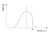
- FIG. 2A is a graph schematically showing the particle size distribution of the conductive particles supplied to the opening
- FIG. 2B is a schematic diagram showing the particle size distribution of the conductive particles held in the opening. It is a graph shown in.
- FIG. 3 is a graph schematically showing another example of the particle size distribution of the conductive particles held in the opening.
- FIG. 4 is a graph schematically showing another example of the particle size distribution of the conductive particles held in the opening.
- FIG. 5 is a graph schematically showing another example of the particle size distribution of the conductive particles held in the opening.
- FIG. 1 is a cross-sectional view schematically showing a state where conductive particles are supplied onto a member having a plurality of openings.
- FIG. 2A is a graph schematically showing the particle size distribution of the conductive particles supplied to the opening
- FIG. 2B is
- FIG. 6A is a graph schematically showing the particle size distribution of conductive particles selected from the lower limit side of the particle size supplied to the opening, and FIG. 6B shows the conductivity held in the opening. It is a graph which shows the particle size distribution of particles typically.
- FIG. 7 is a graph schematically showing another example of the particle size distribution of the conductive particles held in the opening.
- FIG. 8 is a cross-sectional view schematically showing a state in which the adhesive film is opposed to the transfer step.
- FIG. 9 is a cross-sectional view schematically showing a method for manufacturing a connection body according to the present embodiment.
- FIG. 9A shows an arrangement step (S1)
- FIG. 9B shows a curing step ( S2).
- FIG. 1 is a cross-sectional view schematically showing a state where conductive particles are supplied onto a member having a plurality of openings.
- the member 10 is a mold having an opening having an opening size S having a predetermined opening diameter or opening width.
- the mold include metal materials such as stainless steel, transparent inorganic materials such as glass, and organic materials such as poly (meth) acrylate and crystalline resin.
- the opening forming method can be formed by various known techniques. For example, it may be provided by machining, photolithography may be used, or a printing method may be used, and there is no particular limitation.
- the mold can take various shapes such as a plate shape and a roll shape, and is not particularly limited.
- the opening accommodates conductive particles therein, and examples of the shape of the opening include a columnar shape, a polygonal column shape such as a quadrangular column, and a pyramid shape such as a conical shape and a quadrangular pyramid.
- the positions of the openings on the member that is, the positions of the conductive particles arranged in a plane view on the anisotropic conductive film preferably have a specific shape and have regularity, such as a lattice shape, a staggered shape, etc.
- the lattice shape includes an orthorhombic lattice, a hexagonal lattice, a tetragonal lattice, a rectangular lattice, and a parallel lattice. Moreover, you may have regularity with the predetermined arrangement
- the opening size S can be set based on the particle size of the conductive particles arranged on the anisotropic conductive film.
- the ratio of the opening diameter to the desired particle diameter of the conductive particles is preferably 1 from the balance of the ease of accommodating the conductive particles, the ease of pushing in the insulating resin, and the like. .1 to 2.0, more preferably 1.3 to 1.8.
- the ratio of the particle diameter of the conductive particles to the depth of the opening is preferably 0.4 to 3 in view of the balance between the improvement in transferability and the conductive particle retention. 0.0, more preferably 0.5 to 1.5.
- the diameter and depth of the opening can be measured with a laser microscope.
- the average particle diameter of the conductive particles used in the production process can be measured by an image type or laser type particle size distribution meter.
- the use of an image-type particle size distribution meter is preferable because an accurate particle size (particle diameter) can be obtained.
- An example of the image type particle size distribution measuring apparatus is FPIA-3000 (Malvern).
- the opening size S is preferably such that 60% or more of all openings have the same size, more preferably 80% or more of all openings have the same size, and all of the openings have the same size. More preferably.
- the size of the opening is different, any of the plurality of conductive particle diameters is easily held, and when the size of the opening is the same, the particle diameter of the obtained anisotropic conductive film is uniform. Prone. In any case, conductive particles that are significantly larger than the opening are not substantially held in the opening.
- the slope is substantially infinite within the range of the particle size of the maximum peak or more. A graph shape can be obtained.
- the conductive particles having a relatively small size that contributes to the connection may be insufficiently pinched, but the conduction performance is expected to be improved because the conductive particles become a conduction point, and larger conductive particles are used. Since clamping can be controlled within a certain range, it can be expected that a good connection state can be easily obtained. Since this is a metal-coated resin particle, since it is compressed, the compression state can be controlled, and more effects can be expected. It is also possible to reduce the compression hardness and set relatively small conductive particles to the target size for anisotropic connection. Thus, the choice for obtaining conduction performance increases by adjusting the compression hardness of the conductive particles.
- an opening having an opening size S having an upper limit or a lower limit of the ratio of the opening diameters described above may be adjacent, and an opening having an opening size S having an upper limit or a lower limit is anisotropic.
- You may provide periodically in the direction used as the longitudinal direction of a conductive film. This repeating unit of periodicity may be set from the width of the bump and the space between the bumps (L / S). If the arrangement of the openings is set so that the conductive particles are present in the bumps in consideration of the width of the bumps and the space between the bumps, the conductive particles can be reliably arranged at the positions sandwiched by the bumps.
- the distance between the openings can be set as appropriate, but is preferably 0.5 times or more the maximum conductive particle diameter for the purpose of arrangement, and can be set to be equal to or more than the same. In consideration of the presence of relatively small conductive particles, the distance between the openings may be 1.5 times or more, preferably 2 times or more, the maximum conductive particle diameter to be arranged. This can be set as appropriate depending on the size of the conductive particles and the size of the conductive particles to be used and the proportion of the conductive particles used.
- the minimum and maximum openings may be repeated in pairs.
- a plurality of openings having a size between the maximum and minimum may be provided simultaneously.
- any size of conductive particles may be disposed on the anisotropic conductive film, and some may not be disposed. In other words, even if one of them is missing, conduction can be satisfied if the other is present.
- each is preferably 5 or more, more preferably 10 or more, and even more preferably 12 each.
- the distance between the conductive particles is preferably 0.5 times or more, more preferably equal to or more than the maximum conductive particle diameter.
- the arrangement is generally present in a direction perpendicular to the longitudinal direction of the film. This is to satisfy the supplement to one bump. If the conductive particles are arranged in this way, practically any one is supplemented at the time of connection, so that occurrence of poor conduction can be avoided. For example, if the connection surface of the terminal (for example, the connection surface of the Au bump of the IC chip) irregularly has a non-smooth irregular shape, if there is such a pair, any conductive particles will be appropriately You can expect to be supplemented. If it is acceptable that the bumps are not smooth, it is likely to receive cost merit of obtaining a connection body, such as an improvement in yield at the time of bump manufacture and an expansion of an allowable range of design quality.
- the effect of reducing the amount of Au itself can be expected.
- the terminal connection surface has irregular irregularities that are not smooth, if the conductive particles are metal-coated resin particles, they will be compressed, so it can be handled by adjusting the compression hardness Conceivable.
- the surface area increases, so if there are those with different sizes of conductive particles, the connecting surface and the conductive particles are more than those of a single size. It is assumed that the number of contacts with will increase.
- the terminal connection surface is smooth, the effects as described above can be expected by adjusting the particle diameter and the compression hardness.
- the above effects can be avoided by adjusting the arrangement position and number density of the conductive particles in addition to the difference between the maximum and minimum conductive particle diameters and the hardness (compression hardness) of the conductive particles. It is premised on being within an allowable range.
- the method for accommodating the conductive particles in the opening is not particularly limited, and a known method can be employed. For example, by spraying or applying a dried conductive particle powder or a dispersion liquid in which the conductive particle powder is dispersed in a solvent on the opening forming surface of the member 10, the surface of the opening forming surface is squeezed using a brush, a blade, or the like.
- the conductive particles can be accommodated in the opening.
- the conductive particles 20a and 20b smaller than the opening size S are accommodated in the opening, but the conductive particles 20c larger than the opening size S are accommodated in the opening. Sorting can be performed except for conductive particles which are not accommodated and have a large particle size. Thereby, manufacturing cost can be reduced. Further, the cost can be reduced by collecting and reusing the conductive particles after the squeegee.
- the conductive particles those used in known anisotropic conductive films can be appropriately selected and used. Examples thereof include metal particles such as nickel, copper, silver, gold, and palladium, and metal-coated resin particles in which the surfaces of resin particles such as polyamide and polybenzoguanamine are coated with a metal such as nickel.
- the size of the conductive particles to be disposed is preferably 0.5 to 50 ⁇ m, and more preferably 1 to 30 ⁇ m.
- the average particle size of the conductive particles supplied in the holding step (A) is preferably such that the particle size of 0.5 to 50 ⁇ m accounts for 90% or more of the total particle amount from the viewpoint of handleability during production. In addition, it is preferable that the conductive particles less than 1 ⁇ m and larger than 30 ⁇ m are removed in the holding step. As described above, the average particle diameter can be measured by an image type particle size distribution meter, and may be measured from surface observation (surface field observation) after the holding step.
- the surface of the conductive particles is covered with an insulator. Even if the opening size S is slightly larger than the conductive particles, the conductive particles have a surface coating that is easy to peel off and does not interfere with the anisotropic connection, such as an insulating coat or an insulating particle treatment. Can be easily accommodated inside the opening. Since the thickness of such a surface coating varies depending on the connection object, there is no particular limitation as long as it does not hinder the connection.
- the protrusions are preferably within 20%, preferably within 10% of the minimum conductive particle diameter.
- the protrusions are preferably within 20%, preferably within 10% of the minimum conductive particle diameter.
- the conductive particles have relatively high compressibility. That is, it is preferable to use metal-coated resin particles.
- the hardness varies depending on the connection object, and is not particularly limited.
- the compression hardness (K value) at 20% deformation may be in the range of 1000 to 8000 N / mm 2 , and 1000 to 4000 N / mm. A range of 2 is preferred.
- the conductive particles may be intentionally mixed with those having different hardness.
- the compression hardness (K value) at the time of 20% deformation is when the conductive particles are compressed by loading in one direction and the particle size of the conductive particles becomes 20% shorter than the original particle size.
- K (3 / ⁇ 2) F ⁇ S -8/2 ⁇ R -1/2 (1) (Wherein, F: load at the time of 20% compression deformation of conductive particles S: compression displacement (mm) R: radius of conductive particles (mm))
- FIG. 2A is a graph schematically showing the particle size distribution of the conductive particles supplied to the opening
- FIG. 2B is a schematic diagram showing the particle size distribution of the conductive particles held in the opening. It is a graph shown in.
- This particle size distribution graph is a number distribution obtained by measuring the maximum length (particle size) of 1000 or more, preferably 5000 or more conductive particles by surface field observation with an optical microscope or a metal microscope.
- the present method uses a particle whose lower limit side is classified because the particle size distribution of the conductive particles supplied to the opening may be wide (or broad). The effect of facilitating the balance between performance and cost, etc. can be expected, and there is an advantage that choices of availability increase.
- conductive particles having a wide particle size distribution are supplied to the openings, but as shown in FIG. 2 (B), conductive particles held in the openings.
- the particle size distribution graph (X axis: particle size [ ⁇ m], Y axis: number of particles) has a graph shape in which the slope is substantially infinite in a range equal to or larger than the maximum peak particle size.
- the threshold Da is approximately parallel to the Y-axis where the inclination is substantially infinite.
- the fact that the inclination is substantially infinite means that the particle has a straight line parallel to the Y axis, and includes those that approximate a straight line parallel to the Y axis.
- the fact that the inclination is substantially infinite can be paraphrased as having a vertical tangent.
- the particle size distribution of the conductive particles held in the opening is not limited to the graph shape shown in FIG. 2B, and for example, as shown in FIG. 3, the inclination is substantially equal to the maximum peak particle size Db. 4 may be infinite, and as shown in FIG. 4, there may be some conductive particles having a particle diameter Dc or more in which the inclination is substantially infinite.
- there is an upper limit on the particle size of the conductive particles and since the number of particles near the upper limit is relatively small, the number of conductive particles that are insufficiently pushed in is relatively reduced, so that the occurrence of poor conduction can be suppressed. .
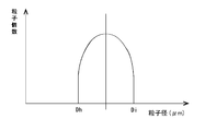
- the particle size distribution of the conductive particles held in the opening has a shape in which a plurality of peaks exist (the bottom exists between the peaks), and the inclination is substantially equal to the particle size Dd. It may be infinite.
- the case where there are a plurality of peaks includes, for example, a case where two types of metal-coated resin particles having different particle diameters are mixed, and the contact between the connection surface and the conductive particles is adjusted by adjusting the compression hardness of the metal-coated resin particles. It is possible to increase the conduction performance.
- the conductive particles to be supplied that are classified on the lower limit side of the particle diameter.
- Conductive particles with a small particle size do not contribute to the connection, so there is not much influence on the conductivity. This is a trade-off between costs, but a relatively large number of conductive particles are required.
- unnecessary superposition of conductive particles (overlap of conductive particles in the thickness direction) and the like can be suppressed.
- conductive particles having a relatively small size contributing to the connection are often held in the opening, and the size contributing to the connection is relatively large. It can be expected that the effect of a spacer that controls the holding of larger conductive particles than the smaller conductive particles in a certain range can be easily adjusted.
- a wet classification method in which vibration having an amplitude of 0.2 to 40 ⁇ m is applied to conductive particles in a liquid and a standard deviation of a short diameter is 10% or less can be cited (for example, JP-A-11-319626). For example).
- FIG. 6A is a graph schematically showing the particle size distribution of the conductive particles classified on the lower limit side of the particle size supplied to the opening, and FIG. 6B shows the conductivity held in the opening. It is a graph which shows the particle size distribution of particles typically.
- the particle size distribution graph (X axis: particle size [ ⁇ m], Y axis: particle amount) of the conductive particles supplied as shown in FIG. 6 (A)
- the inclination is substantially within the range of the maximum peak particle size or less.
- the particle diameter De is preferably infinite.
- the particle size distribution graph (X axis: particle size [ ⁇ m], Y axis: number of particles) of the conductive particles held in the opening is equal to or smaller than the maximum peak particle size.
- the particle diameter Df has a particle diameter Df in which the gradient is substantially infinite in the range, and has a particle diameter Dg in which the gradient is substantially infinite in a range equal to or larger than the particle diameter of the maximum peak.
- the particle size distribution graph (X axis: particle size [ ⁇ m], Y axis: number of particles) of the conductive particles held in the opening slopes within a range equal to or smaller than the maximum peak particle size.
- the conductive particles held in the openings are all within a range of ⁇ 30% of the average particle diameter. It is preferable that 90% or more of the number of particles is present, and it is more preferable that 90% or more of the total number of particles is present in the range of ⁇ 20% of the average particle diameter.
- the capture rate of the conductive particles captured by the bumps can be improved.
- the present technology is not limited to the shape of the particle size distribution graphs shown in FIGS. 2 to 7 and can take various shapes without departing from the gist of the present technology.
- the graph shape shown in FIG. 7 is a symmetric warhead type, but may not be symmetric.
- the adhesive film 30 a known anisotropic conductive film used as an insulating binder layer can be appropriately selected and used.
- the curing type of the adhesive film 30 include a thermosetting type, a photocuring type, and a photothermal combined curing type.
- a cationically polymerizable resin layer, a thermal anionic polymerizable resin layer containing an epoxy compound and a thermal anionic polymerization initiator, or a cured resin layer thereof can be used.
- the anion curable adhesive film contains a film-forming resin, an epoxy resin, and an anionic polymerization initiator.
- the film-forming resin corresponds to, for example, a high molecular weight resin having an average molecular weight of 10,000 or more, and preferably has an average molecular weight of about 10,000 to 80,000 from the viewpoint of film formation.
- the film-forming resin include various resins such as phenoxy resin, polyester resin, polyurethane resin, polyester urethane resin, acrylic resin, polyimide resin, and butyral resin. These may be used alone or in combination of two or more. May be used. Among these, it is preferable to use a phenoxy resin from the viewpoints of film formation state, connection reliability, and the like.
- the epoxy resin forms a three-dimensional network structure and imparts good heat resistance and adhesiveness, and it is preferable to use a solid epoxy resin and a liquid epoxy resin in combination.
- the solid epoxy resin means an epoxy resin that is solid at room temperature.
- the liquid epoxy resin means an epoxy resin that is liquid at room temperature.
- the normal temperature means a temperature range of 5 to 35 ° C. defined by JISZ 8703.
- the solid epoxy resin is not particularly limited as long as it is compatible with a liquid epoxy resin and is solid at room temperature.
- Bisphenol A type epoxy resin bisphenol F type epoxy resin, polyfunctional type epoxy resin, dicyclopentadiene type epoxy resin , Novolak phenol type epoxy resin, biphenyl type epoxy resin, naphthalene type epoxy resin, and the like.
- one kind can be used alone, or two or more kinds can be used in combination.
- the liquid epoxy resin is not particularly limited as long as it is liquid at normal temperature, and examples thereof include bisphenol A type epoxy resin, bisphenol F type epoxy resin, novolac phenol type epoxy resin, naphthalene type epoxy resin, and the like. Can be used alone or in combination of two or more. In particular, it is preferable to use a bisphenol A type epoxy resin from the viewpoint of film tackiness and flexibility.
- anionic polymerization initiator a commonly used known curing agent can be used.
- one kind can be used alone, or two or more kinds can be used in combination.
- it is preferable to use a microcapsule type latent curing agent having an imidazole-modified product as a core and a surface thereof coated with polyurethane.
- a stress relaxation agent examples include a hydrogenated styrene-butadiene block copolymer and a hydrogenated styrene-isoprene block copolymer.
- the silane coupling agent examples include epoxy, methacryloxy, amino, vinyl, mercapto sulfide, and ureido.
- the inorganic filler examples include silica, talc, titanium oxide, calcium carbonate, magnesium oxide and the like.
- This adhesive film 30 can be formed by forming a coating composition containing the above-described resin into a film by a coating method and drying it, or by further curing it, or by previously forming a film by a known method. .
- the thickness of the adhesive film 30 is preferably 1 to 30 ⁇ m, more preferably 2 to 15 ⁇ m. In addition, you may laminate
- the adhesive film 30 is preferably formed on a release film 40 such as a polyethylene terephthalate film subjected to a release treatment.
- Pressure may be applied to the adhesive film 30 from the release film 40 side, and the insulating binder layer may be pushed into the opening, or may be transferred so that the conductive particles 20 are embedded in the surface of the insulating binder layer.
- the particles may be pushed into the insulating binder layer.
- the adhesive film 30 may be laminated as described above before and after these steps. Thereby, a structure in which the conductive particles 20 are arranged in a single layer in the planar direction of the insulating binder layer is formed. In addition, it is preferable that the conductive particles are in a position close to the outermost surface of the adhesive film 30 in order to satisfy the supplement at the time of connection.
- the minimum melt viscosity of the entire insulating binder layer is preferably 100 to 10,000 Pa ⁇ s. Within this range, the conductive particles can be precisely arranged in the insulating binder layer, and it is possible to prevent the resin flow from hindering the trapping property of the conductive particles due to the pressing during anisotropic conductive connection.
- This minimum melt viscosity is determined by using a measuring plate having a diameter of 8 mm, using a rotary rheometer (manufactured by TA Instruments Inc.) as an example, keeping the heating rate constant at 10 ° C./min, measuring pressure at 5 g. Can do.
- the anisotropic conductive film according to the present embodiment includes an insulating binder formed in a film shape, and a plurality of conductive particles arranged in a field of view on the insulating binder, and a particle size distribution graph of the conductive particles ( In the X axis: particle diameter [ ⁇ m], Y axis: number of particles), the graph has a shape in which the slope is substantially infinite in a range equal to or larger than the maximum peak particle diameter.
- the particle size of the X axis is preferably in the range of 1 to 30 ⁇ m.
- This particle size distribution graph is a number distribution obtained by measuring the maximum length (particle size) of 1000 or more, preferably 5000 or more conductive particles by surface field observation with an optical microscope or a metal microscope.
- the shape of the particle size distribution graph of the conductive particles (X axis: particle size [ ⁇ m], Y axis: number of particles) is broad.
- the broad shape which means that the difference between the number cumulative 10% particle diameter D 10 and the number 90% cumulative particle diameter D 90 of from the particle diameter is smaller side is greater than 1 ⁇ m in cumulative distribution.
- the broad shape the difference between the number cumulative 10% particle diameter D 10 and the number 90% cumulative particle diameter D 90 from the side of its small particle size in cumulative distribution is greater than 25% of the average grain size Means.
- the cumulative number of 10% refers to the size (particle diameter) in the number of 10%, rearranged in the order of size (particle diameter) with the total number of particles measured as 100%.
- the conductive particles accommodated in the openings become conductive particles arranged in a plane view on the anisotropic conductive film. That is, as described with reference to the particle size distribution graphs shown in FIGS. 2 to 7, the anisotropic conductive film according to the present embodiment has conductive particles arranged on the upper limit side of the particle size, and the conductive film Since there is an upper limit in the particle size of the particles and the number of particles near the upper limit is large, the occurrence of poor conduction can be suppressed. Note that the conductive particles having a small particle diameter do not contribute to the connection and thus have little influence on the conductivity.
- conductive particles having a wide particle size distribution that is, non-classified or minimum classified conductive particles can be used, it is possible to contribute to reduction of material cost.
- the effect of improving the conduction characteristics can be expected by adjusting the size and hardness (compression hardness) of the conductive particles.
- the particle size distribution graph (X axis: particle diameter [ ⁇ m], Y axis: number of particles) of the conductive particles arranged on the anisotropic conductive film.
- X axis particle diameter [ ⁇ m]
- Y axis number of particles
- the conductive particles having different hardnesses when the conductive particles having different hardnesses are mixed, such a shape can be intentionally formed.
- the hardness is relatively small and the peak having a relatively small particle diameter is used, and the non-hardness is a peak having a relatively large particle diameter, an effect of increasing the supplementary efficiency can be expected.
- the indentation of the conductive particles can be adjusted, contributing to conduction stability.
- the particle diameters of the conductive particles may be measured in advance before the holding step, and simple selection may be performed for each to adjust to a generally appropriate peak. Or you may prepare what shows different particle diameter distribution in each, and may mix it so that it may become a suitable peak in general.
- the inclination is substantially within a range equal to or less than the maximum peak particle size. It is preferable to have an infinite particle size.
- the particle size distribution graph (X axis: particle size [ ⁇ m], Y axis: number of particles) of the conductive particles held in the opening is equal to or smaller than the maximum peak particle size.
- the particle diameter Df has a particle diameter Df in which the gradient is substantially infinite in the range, and has a particle diameter Dg in which the gradient is substantially infinite in a range equal to or larger than the particle diameter of the maximum peak. Further, in order to make the pressure of the conductive particles uniform at the time of pressure bonding, it is preferable that 90% or more of the total number of particles is present in the range of ⁇ 30% of the average particle diameter, and the entire range is within ⁇ 20% of the average particle diameter. It is preferable that 90% or more of the number of particles is present. As described above, by using the conductive particles obtained by classifying the lower limit side of the particle diameter in advance, the capture rate of the conductive particles captured by the bumps can be improved.
- the allowable range of the removal rate of the anisotropic conductive film varies depending on the bump layout of the connection object.
- the drop-off rate is the existence ratio of the number of conductive particles in the length in the width direction of the film and the length in the longitudinal direction. For example, if the bumps are arranged at a high density like COG, the missing rate needs to be small. For example, if the bump area is relatively large like FOG, the missing rate is large. There is no problem.
- this bias is required to be small for COG, and even if it is large to some extent for FOG, there is no problem.
- the use length and width of ACF per one time vary depending on the connection object, but generally the maximum is about 20 mm ⁇ 2 mm. Therefore, if the conductive particle diameter is 10 ⁇ m or less, the continuous area of 2 times, preferably 5 times, and more preferably 10 times of 40 mm 2 is defined as the total area of the anisotropic conductive film, and any of the areas is arbitrary. If there is no significant difference (bias) from the extracted 1 mm 2 , the connection will not be hindered.
- This 1 mm 2 is preferably extracted at 10 locations by extracting (not continuously) an area of 50 ⁇ m in the film longitudinal direction and 200 ⁇ m in the film width direction.
- the area to be evaluated is preferably a rectangular shape with a short longitudinal direction of the film.
- the conductive particle diameter is larger than 10 ⁇ m and not more than 30 ⁇ m, the entire area of the film is left as it is, the film longitudinal direction and the width direction of the area to be extracted are each doubled, and 10 areas that are not 100 ⁇ m ⁇ 400 ⁇ m in area are not continuous. A total of 4 mm 2 may be evaluated by extraction. When the film width is less than 400 ⁇ m, the rectangular shape may be changed as appropriate.
- Such a gap is preferably 50% or more, more preferably 60% or more, and more preferably 70% or more with respect to the maximum value of the number density at 10 locations of 50 ⁇ 200 ⁇ m or 100 ⁇ 400 ⁇ m. Even more preferably.
- the total of the arbitrarily extracted areas is preferably a difference of (1 mm 2 ) ⁇ 30% with respect to the conductive particle number density of the entire area, and may be a difference of ⁇ 20%. More preferable. Within this numerical range, it becomes easy to obtain both cost and performance.
- the anisotropic conductive film described above is preferably a film wound body wound around a roll in order to continuously connect electronic components.
- the length of the film wound body should just be 5 m or more, and it is preferable that it is 10 m or more. Although there is no particular upper limit, it is preferably 5000 m or less, more preferably 1000 m or less, and even more preferably 500 m or less from the viewpoint of handleability of the shipment.
- the film winding body may be one in which anisotropic conductive films shorter than the entire length are connected and connected with a tape. There may be a plurality of connected locations, may exist regularly, or may exist randomly.
- the thickness of the connecting tape is not particularly limited as long as it does not hinder the performance, but if it is too thick, it affects the protrusion and blocking of the resin, and is preferably 10 to 40 ⁇ m.
- the width of the film is not particularly limited, but is 0.5 to 5 mm as an example.
- a method for manufacturing a connection structure according to an embodiment of the present technology includes an insulating binder formed in a film shape and a plurality of conductive particles arranged in a planar view on the insulating binder, and a particle size distribution graph (X In the axis: particle diameter [ ⁇ m], Y axis: number of particles), the first electron passes through the anisotropic conductive film having a graph shape in which the inclination is substantially infinite in the range equal to or larger than the maximum peak particle diameter.
- Arrangement step (S1) for placing the component and the second electronic component, and a curing step (S2) for crimping the second electronic component to the first electronic component by the crimping tool and curing the anisotropic conductive film And have.
- FIG. 9 is a cross-sectional view schematically showing a method for manufacturing a connection body according to the present embodiment.
- FIG. 9A shows an arrangement step (S1)
- FIG. 9B shows a curing step ( S2).
- an anisotropic conductive adhesive film is the same as that of the above-mentioned, description is abbreviate
- the first electronic component 50 includes a first terminal row 51.
- the first electronic component 50 includes LCD (Liquid Crystal Display) panels, flat panel display (FPD) applications such as organic EL (OLED), transparent substrates for touch panel applications, printed wiring boards (PWB), and the like. It is done.
- the material of the printed wiring board is not particularly limited. For example, glass epoxy such as FR-4 base material, plastic such as thermoplastic resin, ceramic, or the like can be used.
- the transparent substrate is not particularly limited as long as it has high transparency, and examples thereof include a glass substrate and a plastic substrate.
- the second electronic component 70 includes a second terminal row 71 that faces the first terminal row 51.
- the 2nd electronic component 70 does not have a restriction
- the second electronic component 70 include an IC (IntegratedIntegrCircuit), a flexible substrate (FPC: Flexible Printed Circuits), a tape carrier package (TCP) substrate, and a COF (Chip On Film) having an IC mounted on the FPC. It is done.
- connection structure manufacturing method excellent conductivity can be obtained as in the case of using an anisotropic conductive film containing conductive particles classified in advance.
- connection structure includes a first electronic component, a second electronic component, and an adhesive film in which the first electronic component and the second electronic component are bonded.
- an insulating binder formed in a film shape, and a plurality of conductive particles arranged in a field of view on the insulating binder, and a particle size distribution graph of the conductive particles (X axis: particle diameter [ ⁇ m], Y axis) : Number of particles), the anisotropic conductive film having a graph shape in which the inclination is substantially infinite in a range equal to or larger than the maximum peak particle diameter is cured.
- connection structure excellent conductivity can be obtained as in the case of bonding using an anisotropic conductive film containing conductive particles classified in advance.
- this technique is applicable not only to the application to the manufacturing method of the connection structure mentioned above but also when stacking IC chips and wafers to make a multilayer.
- Manufacturing method of filler-arranged film and filler-arranged film> The manufacturing method of the anisotropic conductive film mentioned above can manufacture the filler arrangement
- the method for producing a filler-arranged film supplies a filler having a plurality of particle diameters on a member having a plurality of openings, and holds the filler in the openings, and the openings.
- the graph has a gradient that is substantially infinite in a range equal to or larger than the particle diameter.
- this method balances performance and cost, such as using a particle whose lower limit is classified. There is an advantage that the effect of facilitating the expectation can be expected, and the options of availability increase.
- an inorganic filler or an organic filler can be used depending on the use of the filler-arranged film.
- the inorganic filler include silica, calcium carbonate, talc, barium sulfate, aluminum hydroxide, aluminum oxide, magnesium hydroxide, magnesium oxide, titanium oxide, zinc oxide, iron oxide, mica and the like.
- organic filler well-known resin fillers, such as a silicone resin, a fluororesin, and a polybutadiene resin, rubber particles, etc. are mentioned, for example.
- examples of the filler include silica, calcium carbonate, known resin fillers, rubber particles, and the like, and the filler-arranged film is excellent because the particle diameter of the filler is uniform. Functions as a gap spacer.
- examples of the filler include titanium oxide, zinc oxide, iron oxide, or a known resin filler. Is arranged at a predetermined position in the surface field of view, so that excellent optical performance can be obtained.
- examples of the filler include colored fillers (regardless of inorganic and organic substances), and the filler-arranged film is arranged at a predetermined position in a plane view, Excellent design properties can be obtained.
- the member having a plurality of openings and the adhesive film are the same as those described in the method for manufacturing the anisotropic conductive film described above, description thereof is omitted here.
- the filler-arranged film according to the present embodiment includes an insulating binder formed in a film shape and a plurality of fillers arranged in a plane field of view on the insulating binder, and a particle size distribution graph of the filler (X axis: particles) In the diameter [ ⁇ m], the Y axis: the number of particles), the graph has a shape in which the slope is substantially infinite in a range equal to or larger than the maximum peak particle size.
- the filler particle size distribution is cut with a large particle size and arranged in a plane view.
- a conductive member other than the method of using an anisotropic conductive film known as a conductive particle It can be set as the use to be used, a gap spacer, an optical member, a design member, or the like.
- the conductive particles mixed at a predetermined ratio (number conversion) are supplied to the resin mold on which the opening array pattern is formed, the conductive particles are held in the openings, and the conductive particles held in the openings are bonded.
- An anisotropic conductive film was produced by transferring to a film. And classification evaluation of the anisotropic conductive film was performed.
- the connection structure was produced using the anisotropic conductive film, and the continuity evaluation, the supplementary evaluation, and the short evaluation of the connection structure were performed. Note that the present technology is not limited to these examples. For example, the effect similar to the result of the classification evaluation of an anisotropic conductive film is obtained also about the manufacturing method of the filler arrangement
- the height of the convex portion (that is, the depth of the opening) was 3.5 ⁇ m.
- a known transparent resin pellet was poured into this mold in a molten state, and cooled and hardened to form a resin mold having an opening array pattern.
- the opening depth of the obtained resin mold was almost the same as the height of the convex portion.
- a resin composition A having the following composition was coated on a PET film having a film thickness of 50 ⁇ m with a bar coater and dried in an oven at 80 ° C. for 5 minutes to form an insulating resin layer A having a thickness of 4 ⁇ m on the PET film. .
- Resin composition A (insulating resin layer A) Phenoxy resin (YP-50, Nippon Steel & Sumikin Chemical Co., Ltd.): 30 parts by mass, epoxy resin (jER828, Mitsubishi Chemical Co., Ltd.): 40 parts by mass, cationic curing agent (SI-60L, Sanshin Chemical Industry Co., Ltd.) ): 2 parts by mass, filler (Aerosil RX300, Nippon Aerosil Co., Ltd.): 30 parts by mass
- a resin composition B having the following composition was coated on a PET film having a film thickness of 50 ⁇ m with a bar coater and dried in an oven at 80 ° C. for 5 minutes to form an insulating resin layer B having a thickness of 14 ⁇ m on the PET film. .
- Resin composition B (insulating resin layer B) Phenoxy resin (YP-50, Nippon Steel & Sumikin Chemical Co., Ltd.): 30 parts by mass, Phenoxy resin (FX-316ATM55, Nippon Steel & Sumikin Chemical Co., Ltd.): 30 parts by mass, epoxy resin (jER828, Mitsubishi Chemical Co., Ltd.): 40 parts by mass, cationic curing agent (SI-60L, Sanshin Chemical Industry Co., Ltd.): 2 parts by mass
- 3 ⁇ m metal-coated resin particles (Sekisui Chemical Co., Ltd., AUL703, average particle diameter of 3 ⁇ m, hereinafter referred to as “3 ⁇ m diameter particles”), and 5 ⁇ m metal-coated resin particles (Sekisui Chemical Co., Ltd.) AUL705, an average particle diameter of 5 ⁇ m, and hereinafter referred to as “5 ⁇ m diameter particles”) were prepared.
- Conductive particles A were obtained by weighing into a container such that 3 ⁇ m diameter particles were 80% in terms of number and 5 ⁇ m diameter particles were 20% and mixed well. To confirm the mixing, a small amount of the mixture was taken out, spread on an adhesive film, and observed with a metal microscope. This was repeated 3 to 10 times to confirm that the mixed state was uniform.
- the conductive particles A are filled in the resin-type depressions in which the opening array pattern is formed, and the insulating resin layer A is covered thereon and pressed at 60 ° C. and 0.5 MPa, so that the conductive particles A are insulated from the resin. The layers were stuck. Then, the insulating resin layer A is peeled off from the resin mold, and the conductive particles on the insulating resin layer A are pressurized (pressing conditions: 60 to 70 ° C., 0.5 Mpa) to thereby remove the conductive particles A from the insulating resin. It pressed into the layer A and produced the conductive particle content layer.
- Conductive particles B mixed such that 3 ⁇ m diameter particles are 75% in terms of number and 5 ⁇ m diameter particles are 25%, and mixed so that 3 ⁇ m diameter particles are 50% in terms of number and 5 ⁇ m diameter particles are 50%.
- Conductive particles C, conductive particles D mixed such that 3 ⁇ m diameter particles are 40% in terms of number and 5 ⁇ m diameter particles are 60%, and conductive particles E in which 3 ⁇ m diameter particles are 100% in terms of number are also described above.
- anisotropic conductive films B to E were produced.
- the anisotropic conductive films A to D had a particle omission in the arrangement as the number ratio of 3 ⁇ m diameter particles of the used conductive particles was lower, but anisotropic using only 3 ⁇ m diameter particles as described later.
- the same performance as that of the conductive conductive film E was exhibited, and there was no practical problem.
- the particle size distribution of the conductive particles in the conductive particle-containing layers in the anisotropic conductive films A to E was measured using a particle size distribution measuring apparatus (FPIA-3000 (Malvern)).
- connection structure [Evaluation of continuity of connection structure]
- the anisotropic conductive films A to E were sandwiched between the conductivity evaluation IC and the glass substrate, and heated and pressurized (180 ° C., 60 MPa, 5 seconds) to produce a connection structure for conductivity evaluation. And the conduction resistance of each connection structure was measured after the reliability test which left still for 500 hours at the initial stage after connection, and the temperature 85 degreeC and the humidity 85% RH.
- the initial conduction resistance was less than 0.5 ⁇ , and the conduction resistance after the reliability test was less than 5 ⁇ . That is, the anisotropic conductive films A to D showed the same performance as the anisotropic conductive film E using only 3 ⁇ m diameter particles, and it was found that there is no practical problem.
- Conductivity evaluation IC Outline 1.8 ⁇ 20.0mm Thickness 0.5mm Bump specifications Size 30 ⁇ 85 ⁇ m, distance between bumps 50 ⁇ m, bump height 15 ⁇ m
- connection structure for conductivity evaluation, an indentation inspection was performed on the captured state of the conductive particles. As a result, in all of the anisotropic conductive films A to E, it was confirmed that at least three or more conductive particles per bump were independent indentations. As for the number of traps, the higher the mixing ratio of 3 ⁇ m diameter particles, the greater the number of captures, and the anisotropic conductive film E using only the 3 ⁇ m diameter had the largest number of traps.
- connection structure For each connection structure for continuity evaluation, the number of shorted channels in 100 bumps was measured and taken as the number of shorts. As a result, none of the connection structures using the anisotropic conductive films A to E were short-circuited.
- anisotropic conductive films A to E are sandwiched between a short-circuit occurrence rate evaluation IC and a glass substrate having a pattern corresponding to the evaluation IC, and are heated and pressurized (180 ° C., 60 MPa, 5 seconds) to conduct.
- a connection structure for property evaluation was prepared.
- the number of channels shorted between the bumps was defined as the number of shorts, and the short-circuit occurrence rate calculated by “number of shorts / total number of 7.5 ⁇ m spaces” was obtained.
- the occurrence rate of short circuit was less than 50 ppm. Note that there is no practical problem if the short-circuit occurrence rate is less than 50 ppm.
- IC for short-circuit incidence evaluation (comb tooth TEG (Test Element Group)) External dimensions 1.5 x 13 mm Thickness 0.5mm Bump specifications Gold plating, height 15 ⁇ m, size 25 ⁇ 140 ⁇ m, distance between bumps 7.5 ⁇ m
- the anisotropic conductive films A to D to which the present technology is applied are classified into particles having a diameter of 3 ⁇ m in any of the classification evaluation of the anisotropic conductive film, the continuity evaluation of the connection structure, the supplementary evaluation, and the short evaluation. It was equivalent to the anisotropic conductive film E used, and it was found that there was no practical problem. That is, by applying the present technology, conductive particles having a broad particle size distribution can be used, and the manufacturing cost can be reduced. Moreover, it turns out that the same effect is acquired also from a filler arrangement
- the conductive particles having a large particle diameter are removed, but the conductive particles having a small particle diameter may be removed in advance by a known method.
- a method for removing conductive particles having a small particle diameter for example, a wet classification method in which vibration having an amplitude of 0.2 to 40 ⁇ m is applied to conductive particles in a liquid and a standard deviation of a short diameter is 10% or less. Etc.
Landscapes
- Chemical & Material Sciences (AREA)
- Engineering & Computer Science (AREA)
- Manufacturing & Machinery (AREA)
- Spectroscopy & Molecular Physics (AREA)
- Physics & Mathematics (AREA)
- Dispersion Chemistry (AREA)
- Organic Chemistry (AREA)
- Health & Medical Sciences (AREA)
- Chemical Kinetics & Catalysis (AREA)
- Medicinal Chemistry (AREA)
- Polymers & Plastics (AREA)
- Non-Insulated Conductors (AREA)
- Adhesive Tapes (AREA)
Abstract
L'invention concerne un procédé de fabrication d'un film conducteur anisotrope permettant de réduire les coûts de fabrication. L'invention concerne également un film conducteur anisotrope permettant de supprimer la survenue d'une défaillance de conduction. Le procédé de fabrication du film conducteur anisotrope selon l'invention comprend : une étape de maintien destinée à acheminer des particules conductrices d'une pluralité de diamètres de particule (20a à 20c) sur un élément (10) comportant une pluralité de parties d'ouverture, et à maintenir les particules conductrices dans les parties d'ouverture ; ainsi qu'une étape de transfert destinée à transférer les particules conductrices maintenues dans les parties d'ouverture vers un film adhésif. Sur le graphique de répartition de diamètres des particules conductrices maintenues dans les parties d'ouverture (axe X : diamètre de particule [µm], axe Y : nombre de particules), la forme du graphique est telle que, sur la plage de diamètre de particule de pic maximal ou supérieur, la pente est sensiblement infinie.
Priority Applications (5)
| Application Number | Priority Date | Filing Date | Title |
|---|---|---|---|
| US16/087,526 US11004574B2 (en) | 2016-05-02 | 2017-04-25 | Method for manufacturing anisotropic conductive film, and anisotropic conductive film |
| KR1020187029867A KR102246259B1 (ko) | 2016-05-02 | 2017-04-25 | 이방성 도전 필름의 제조 방법 및 이방성 도전 필름 |
| CN201780020535.7A CN108886227B (zh) | 2016-05-02 | 2017-04-25 | 各向异性导电膜的制造方法及各向异性导电膜 |
| KR1020217012297A KR102445646B1 (ko) | 2016-05-02 | 2017-04-25 | 이방성 도전 필름의 제조 방법 및 이방성 도전 필름 |
| US17/315,862 US12014840B2 (en) | 2016-05-02 | 2021-05-10 | Method for manufacturing anisotropic conductive film, and anisotropic conductive film |
Applications Claiming Priority (4)
| Application Number | Priority Date | Filing Date | Title |
|---|---|---|---|
| JP2016-092832 | 2016-05-02 | ||
| JP2016092832 | 2016-05-02 | ||
| JP2017-085492 | 2017-04-24 | ||
| JP2017085492A JP6889020B2 (ja) | 2016-05-02 | 2017-04-24 | 異方性導電フィルムの製造方法、及び異方性導電フィルム |
Related Child Applications (2)
| Application Number | Title | Priority Date | Filing Date |
|---|---|---|---|
| US16/087,526 A-371-Of-International US11004574B2 (en) | 2016-05-02 | 2017-04-25 | Method for manufacturing anisotropic conductive film, and anisotropic conductive film |
| US17/315,862 Continuation US12014840B2 (en) | 2016-05-02 | 2021-05-10 | Method for manufacturing anisotropic conductive film, and anisotropic conductive film |
Publications (1)
| Publication Number | Publication Date |
|---|---|
| WO2017191776A1 true WO2017191776A1 (fr) | 2017-11-09 |
Family
ID=60203042
Family Applications (1)
| Application Number | Title | Priority Date | Filing Date |
|---|---|---|---|
| PCT/JP2017/016255 Ceased WO2017191776A1 (fr) | 2016-05-02 | 2017-04-25 | Procédé de fabrication de film conducteur anisotrope et film conducteur anisotrope |
Country Status (3)
| Country | Link |
|---|---|
| KR (1) | KR102445646B1 (fr) |
| TW (1) | TWI775562B (fr) |
| WO (1) | WO2017191776A1 (fr) |
Cited By (4)
| Publication number | Priority date | Publication date | Assignee | Title |
|---|---|---|---|---|
| CN110054996A (zh) * | 2018-01-18 | 2019-07-26 | 拓自达电线株式会社 | 导电性接合膜及使用该导电性接合膜的电磁波屏蔽膜 |
| WO2019188372A1 (fr) * | 2018-03-30 | 2019-10-03 | デクセリアルズ株式会社 | Matériau conducteur et procédé de fabrication de corps de connexion |
| CN117279715A (zh) * | 2021-05-11 | 2023-12-22 | 株式会社力森诺科 | 焊料粒子的分级方法、焊料粒子、焊料粒子的分级系统、黏合剂组合物及黏合剂膜 |
| WO2025105288A1 (fr) * | 2023-11-17 | 2025-05-22 | 株式会社レゾナック | Procédé de fabrication de corps enroulé de film adhésif pour connexion de circuit, et corps enroulé de film adhésif pour connexion de circuit |
Citations (8)
| Publication number | Priority date | Publication date | Assignee | Title |
|---|---|---|---|---|
| JP2007297636A (ja) * | 2007-06-14 | 2007-11-15 | Nippon Zeon Co Ltd | 異方性導電用樹脂組成物 |
| JP2008300360A (ja) * | 1995-02-07 | 2008-12-11 | Hitachi Chem Co Ltd | 電極の接続方法 |
| JP2010176910A (ja) * | 2009-01-27 | 2010-08-12 | Panasonic Electric Works Co Ltd | 導電性シート材料及び電気的接続構造 |
| WO2013005831A1 (fr) * | 2011-07-07 | 2013-01-10 | 日立化成工業株式会社 | Matière de connexion de circuits et structure de carte de circuits connectés |
| JP2013055045A (ja) * | 2011-08-05 | 2013-03-21 | Sekisui Chem Co Ltd | 接続構造体の製造方法、接続構造体及び異方性導電材料 |
| JP2013258136A (ja) * | 2012-05-14 | 2013-12-26 | Sekisui Chem Co Ltd | 導電性粒子材料、導電材料、接続構造体及び接続構造体の製造方法 |
| JP2014060151A (ja) * | 2012-08-24 | 2014-04-03 | Dexerials Corp | 異方性導電フィルムの製造方法及び異方性導電フィルム |
| JP2015135748A (ja) * | 2014-01-17 | 2015-07-27 | デクセリアルズ株式会社 | 異方性導電フィルム、接続構造体、接続構造体の製造方法、及び接続構造体の製造装置 |
Family Cites Families (11)
| Publication number | Priority date | Publication date | Assignee | Title |
|---|---|---|---|---|
| JP4016491B2 (ja) * | 1998-07-29 | 2007-12-05 | 凸版印刷株式会社 | スキージとスキージング機構およびそれを用いたスクリーン印刷方法 |
| JP2004223788A (ja) * | 2003-01-21 | 2004-08-12 | Yamaha Motor Co Ltd | スキージ及びスクリーン印刷機 |
| CN100537689C (zh) * | 2003-12-04 | 2009-09-09 | 旭化成电子材料株式会社 | 各向异性的导电粘合片材及连接结构体 |
| KR100591074B1 (ko) * | 2004-12-13 | 2006-06-19 | (주) 선양디엔티 | 칩 온 필름용 이방성 도전물 부착 시스템 |
| JP4890053B2 (ja) * | 2006-03-02 | 2012-03-07 | 旭化成イーマテリアルズ株式会社 | 微細回路検査用異方導電性フィルム |
| KR100787381B1 (ko) * | 2006-11-16 | 2007-12-24 | 한국과학기술연구원 | 미세 캡슐-도전성 입자 복합체, 이의 제조 방법 및 이를이용한 이방 도전성 접착 필름 |
| KR101570398B1 (ko) * | 2012-04-26 | 2015-11-19 | 오사카 유니버시티 | 투명 도전성 잉크 및 투명 도전 패턴형성방법 |
| JP5972844B2 (ja) * | 2012-09-18 | 2016-08-17 | デクセリアルズ株式会社 | 異方性導電フィルム、異方性導電フィルムの製造方法、接続体の製造方法、及び接続方法 |
| JP2015034279A (ja) * | 2013-04-10 | 2015-02-19 | デクセリアルズ株式会社 | 透明導電膜形成用インク組成物、透明導電膜、透明電極の製造方法、及び画像表示装置 |
| US20160155717A1 (en) * | 2013-07-31 | 2016-06-02 | Dexerials Corporation | Anisotropic conductive film and manufacturing method therefor |
| JPWO2015068654A1 (ja) * | 2013-11-05 | 2017-03-09 | 昭和電工株式会社 | 導電パターン形成方法及びこれを使用したオンセル型タッチパネルの製造方法並びにこれに使用する転写用フィルム及びオンセル型タッチパネル |
-
2017
- 2017-04-25 WO PCT/JP2017/016255 patent/WO2017191776A1/fr not_active Ceased
- 2017-04-25 KR KR1020217012297A patent/KR102445646B1/ko active Active
- 2017-05-01 TW TW110129669A patent/TWI775562B/zh active
Patent Citations (8)
| Publication number | Priority date | Publication date | Assignee | Title |
|---|---|---|---|---|
| JP2008300360A (ja) * | 1995-02-07 | 2008-12-11 | Hitachi Chem Co Ltd | 電極の接続方法 |
| JP2007297636A (ja) * | 2007-06-14 | 2007-11-15 | Nippon Zeon Co Ltd | 異方性導電用樹脂組成物 |
| JP2010176910A (ja) * | 2009-01-27 | 2010-08-12 | Panasonic Electric Works Co Ltd | 導電性シート材料及び電気的接続構造 |
| WO2013005831A1 (fr) * | 2011-07-07 | 2013-01-10 | 日立化成工業株式会社 | Matière de connexion de circuits et structure de carte de circuits connectés |
| JP2013055045A (ja) * | 2011-08-05 | 2013-03-21 | Sekisui Chem Co Ltd | 接続構造体の製造方法、接続構造体及び異方性導電材料 |
| JP2013258136A (ja) * | 2012-05-14 | 2013-12-26 | Sekisui Chem Co Ltd | 導電性粒子材料、導電材料、接続構造体及び接続構造体の製造方法 |
| JP2014060151A (ja) * | 2012-08-24 | 2014-04-03 | Dexerials Corp | 異方性導電フィルムの製造方法及び異方性導電フィルム |
| JP2015135748A (ja) * | 2014-01-17 | 2015-07-27 | デクセリアルズ株式会社 | 異方性導電フィルム、接続構造体、接続構造体の製造方法、及び接続構造体の製造装置 |
Cited By (8)
| Publication number | Priority date | Publication date | Assignee | Title |
|---|---|---|---|---|
| CN110054996A (zh) * | 2018-01-18 | 2019-07-26 | 拓自达电线株式会社 | 导电性接合膜及使用该导电性接合膜的电磁波屏蔽膜 |
| CN110054996B (zh) * | 2018-01-18 | 2021-09-14 | 拓自达电线株式会社 | 导电性接合膜及使用该导电性接合膜的电磁波屏蔽膜 |
| WO2019188372A1 (fr) * | 2018-03-30 | 2019-10-03 | デクセリアルズ株式会社 | Matériau conducteur et procédé de fabrication de corps de connexion |
| JP2019179647A (ja) * | 2018-03-30 | 2019-10-17 | デクセリアルズ株式会社 | 導電材料、及び接続体の製造方法 |
| JP2022173197A (ja) * | 2018-03-30 | 2022-11-18 | デクセリアルズ株式会社 | 導電フィルム、接続体の製造方法及び接続体 |
| JP7420883B2 (ja) | 2018-03-30 | 2024-01-23 | デクセリアルズ株式会社 | 導電フィルム、接続体の製造方法及び接続体 |
| CN117279715A (zh) * | 2021-05-11 | 2023-12-22 | 株式会社力森诺科 | 焊料粒子的分级方法、焊料粒子、焊料粒子的分级系统、黏合剂组合物及黏合剂膜 |
| WO2025105288A1 (fr) * | 2023-11-17 | 2025-05-22 | 株式会社レゾナック | Procédé de fabrication de corps enroulé de film adhésif pour connexion de circuit, et corps enroulé de film adhésif pour connexion de circuit |
Also Published As
| Publication number | Publication date |
|---|---|
| KR102445646B1 (ko) | 2022-09-21 |
| KR20210048602A (ko) | 2021-05-03 |
| TWI775562B (zh) | 2022-08-21 |
| TW202147351A (zh) | 2021-12-16 |
Similar Documents
| Publication | Publication Date | Title |
|---|---|---|
| US11794444B2 (en) | Anisotropic conductive film | |
| KR102149964B1 (ko) | 이방성 도전 필름 | |
| US10899949B2 (en) | Filler-containing film | |
| JP7315878B2 (ja) | フィラー含有フィルム | |
| US10854571B2 (en) | Anisotropic conductive film with conductive particles forming repeating units of polygons | |
| KR20210158875A (ko) | 필러 함유 필름 | |
| KR20190038603A (ko) | 필러 함유 필름 | |
| US12365772B2 (en) | Filler-containing film | |
| KR102445646B1 (ko) | 이방성 도전 필름의 제조 방법 및 이방성 도전 필름 | |
| JP7332956B2 (ja) | フィラー含有フィルム | |
| JP2022126655A (ja) | フィラー含有フィルム | |
| KR20210046827A (ko) | 이방성 도전 필름 | |
| JP7194229B2 (ja) | 異方性導電フィルムの製造方法、及び異方性導電フィルム | |
| HK1260569A1 (en) | Method for manufacturing anisotropic conductive film, and anisotropic conductive film | |
| HK1260569B (en) | Method for manufacturing anisotropic conductive film, and anisotropic conductive film |
Legal Events
| Date | Code | Title | Description |
|---|---|---|---|
| DPE1 | Request for preliminary examination filed after expiration of 19th month from priority date (pct application filed from 20040101) | ||
| ENP | Entry into the national phase |
Ref document number: 20187029867 Country of ref document: KR Kind code of ref document: A |
|
| NENP | Non-entry into the national phase |
Ref country code: DE |
|
| 121 | Ep: the epo has been informed by wipo that ep was designated in this application |
Ref document number: 17792709 Country of ref document: EP Kind code of ref document: A1 |
|
| 122 | Ep: pct application non-entry in european phase |
Ref document number: 17792709 Country of ref document: EP Kind code of ref document: A1 |