WO2017191972A2 - Appareil de charge automatique de téléphone intelligent - Google Patents
Appareil de charge automatique de téléphone intelligent Download PDFInfo
- Publication number
- WO2017191972A2 WO2017191972A2 PCT/KR2017/004644 KR2017004644W WO2017191972A2 WO 2017191972 A2 WO2017191972 A2 WO 2017191972A2 KR 2017004644 W KR2017004644 W KR 2017004644W WO 2017191972 A2 WO2017191972 A2 WO 2017191972A2
- Authority
- WO
- WIPO (PCT)
- Prior art keywords
- smartphone
- charging
- self
- coil
- frame
- Prior art date
- Legal status (The legal status is an assumption and is not a legal conclusion. Google has not performed a legal analysis and makes no representation as to the accuracy of the status listed.)
- Ceased
Links
Images


Classifications
-
- H—ELECTRICITY
- H04—ELECTRIC COMMUNICATION TECHNIQUE
- H04M—TELEPHONIC COMMUNICATION
- H04M19/00—Current supply arrangements for telephone systems
- H04M19/08—Current supply arrangements for telephone systems with current supply sources at the substations
-
- H—ELECTRICITY
- H02—GENERATION; CONVERSION OR DISTRIBUTION OF ELECTRIC POWER
- H02J—ELECTRIC POWER NETWORKS; CIRCUIT ARRANGEMENTS OR SYSTEMS FOR SUPPLYING OR DISTRIBUTING ELECTRIC POWER; SYSTEMS FOR STORING ELECTRIC ENERGY
- H02J7/00—Circuit arrangements for charging or discharging batteries or for supplying loads from batteries
- H02J7/14—Circuit arrangements for charging or discharging batteries or for supplying loads from batteries for charging batteries from dynamo-electric generators driven at varying speed, e.g. on vehicle
- H02J7/1415—Circuit arrangements for charging or discharging batteries or for supplying loads from batteries for charging batteries from dynamo-electric generators driven at varying speed, e.g. on vehicle with a generator driven by a prime mover other than the motor of a vehicle
-
- H—ELECTRICITY
- H01—ELECTRIC ELEMENTS
- H01M—PROCESSES OR MEANS, e.g. BATTERIES, FOR THE DIRECT CONVERSION OF CHEMICAL ENERGY INTO ELECTRICAL ENERGY
- H01M10/00—Secondary cells; Manufacture thereof
- H01M10/42—Methods or arrangements for servicing or maintenance of secondary cells or secondary half-cells
- H01M10/46—Accumulators structurally combined with charging apparatus
- H01M10/465—Accumulators structurally combined with charging apparatus with solar battery as charging system
-
- H—ELECTRICITY
- H02—GENERATION; CONVERSION OR DISTRIBUTION OF ELECTRIC POWER
- H02J—ELECTRIC POWER NETWORKS; CIRCUIT ARRANGEMENTS OR SYSTEMS FOR SUPPLYING OR DISTRIBUTING ELECTRIC POWER; SYSTEMS FOR STORING ELECTRIC ENERGY
- H02J7/00—Circuit arrangements for charging or discharging batteries or for supplying loads from batteries
- H02J7/14—Circuit arrangements for charging or discharging batteries or for supplying loads from batteries for charging batteries from dynamo-electric generators driven at varying speed, e.g. on vehicle
-
- H—ELECTRICITY
- H02—GENERATION; CONVERSION OR DISTRIBUTION OF ELECTRIC POWER
- H02J—ELECTRIC POWER NETWORKS; CIRCUIT ARRANGEMENTS OR SYSTEMS FOR SUPPLYING OR DISTRIBUTING ELECTRIC POWER; SYSTEMS FOR STORING ELECTRIC ENERGY
- H02J7/00—Circuit arrangements for charging or discharging batteries or for supplying loads from batteries
- H02J7/34—Parallel operation in networks using both storage and other DC sources, e.g. providing buffering
- H02J7/35—Parallel operation in networks using both storage and other DC sources, e.g. providing buffering with light sensitive cells
-
- H—ELECTRICITY
- H02—GENERATION; CONVERSION OR DISTRIBUTION OF ELECTRIC POWER
- H02K—DYNAMO-ELECTRIC MACHINES
- H02K7/00—Arrangements for handling mechanical energy structurally associated with dynamo-electric machines, e.g. structural association with mechanical driving motors or auxiliary dynamo-electric machines
- H02K7/18—Structural association of electric generators with mechanical driving motors, e.g. with turbines
- H02K7/1807—Rotary generators
- H02K7/1853—Rotary generators driven by intermittent forces
-
- H—ELECTRICITY
- H02—GENERATION; CONVERSION OR DISTRIBUTION OF ELECTRIC POWER
- H02S—GENERATION OF ELECTRIC POWER BY CONVERSION OF INFRARED RADIATION, VISIBLE LIGHT OR ULTRAVIOLET LIGHT, e.g. USING PHOTOVOLTAIC [PV] MODULES
- H02S40/00—Components or accessories in combination with PV modules, not provided for in groups H02S10/00 - H02S30/00
- H02S40/30—Electrical components
- H02S40/38—Energy storage means, e.g. batteries, structurally associated with PV modules
-
- H—ELECTRICITY
- H04—ELECTRIC COMMUNICATION TECHNIQUE
- H04M—TELEPHONIC COMMUNICATION
- H04M1/00—Substation equipment, e.g. for use by subscribers
- H04M1/02—Constructional features of telephone sets
-
- H—ELECTRICITY
- H04—ELECTRIC COMMUNICATION TECHNIQUE
- H04M—TELEPHONIC COMMUNICATION
- H04M1/00—Substation equipment, e.g. for use by subscribers
- H04M1/02—Constructional features of telephone sets
- H04M1/0202—Portable telephone sets, e.g. cordless phones, mobile phones or bar type handsets
- H04M1/0279—Improving the user comfort or ergonomics
- H04M1/0283—Improving the user comfort or ergonomics for providing a decorative aspect, e.g. customization of casings, exchangeable faceplate
-
- Y—GENERAL TAGGING OF NEW TECHNOLOGICAL DEVELOPMENTS; GENERAL TAGGING OF CROSS-SECTIONAL TECHNOLOGIES SPANNING OVER SEVERAL SECTIONS OF THE IPC; TECHNICAL SUBJECTS COVERED BY FORMER USPC CROSS-REFERENCE ART COLLECTIONS [XRACs] AND DIGESTS
- Y02—TECHNOLOGIES OR APPLICATIONS FOR MITIGATION OR ADAPTATION AGAINST CLIMATE CHANGE
- Y02E—REDUCTION OF GREENHOUSE GAS [GHG] EMISSIONS, RELATED TO ENERGY GENERATION, TRANSMISSION OR DISTRIBUTION
- Y02E10/00—Energy generation through renewable energy sources
- Y02E10/50—Photovoltaic [PV] energy
-
- Y—GENERAL TAGGING OF NEW TECHNOLOGICAL DEVELOPMENTS; GENERAL TAGGING OF CROSS-SECTIONAL TECHNOLOGIES SPANNING OVER SEVERAL SECTIONS OF THE IPC; TECHNICAL SUBJECTS COVERED BY FORMER USPC CROSS-REFERENCE ART COLLECTIONS [XRACs] AND DIGESTS
- Y02—TECHNOLOGIES OR APPLICATIONS FOR MITIGATION OR ADAPTATION AGAINST CLIMATE CHANGE
- Y02E—REDUCTION OF GREENHOUSE GAS [GHG] EMISSIONS, RELATED TO ENERGY GENERATION, TRANSMISSION OR DISTRIBUTION
- Y02E60/00—Enabling technologies; Technologies with a potential or indirect contribution to GHG emissions mitigation
- Y02E60/10—Energy storage using batteries
-
- Y—GENERAL TAGGING OF NEW TECHNOLOGICAL DEVELOPMENTS; GENERAL TAGGING OF CROSS-SECTIONAL TECHNOLOGIES SPANNING OVER SEVERAL SECTIONS OF THE IPC; TECHNICAL SUBJECTS COVERED BY FORMER USPC CROSS-REFERENCE ART COLLECTIONS [XRACs] AND DIGESTS
- Y02—TECHNOLOGIES OR APPLICATIONS FOR MITIGATION OR ADAPTATION AGAINST CLIMATE CHANGE
- Y02E—REDUCTION OF GREENHOUSE GAS [GHG] EMISSIONS, RELATED TO ENERGY GENERATION, TRANSMISSION OR DISTRIBUTION
- Y02E70/00—Other energy conversion or management systems reducing GHG emissions
- Y02E70/30—Systems combining energy storage with energy generation of non-fossil origin
Definitions
- the present invention relates to a self-charging device for a smart phone, and more particularly, a structure and a function are improved to accommodate a smart phone to protect it from an external shock and at the same time to charge and use a smart phone in an emergency. It relates to a self-charging device for a smartphone.
- auxiliary batteries have been introduced to extend the usage time of smartphones.
- auxiliary batteries are configured separately from smartphones. Therefore, the user must carry the smartphone and the auxiliary battery, respectively.
- the user may charge the battery by connecting the auxiliary battery to the smartphone.
- Such a general auxiliary battery also has a problem in that charging is performed through an external power supply when the remaining battery amount is exhausted.
- the general auxiliary battery has a problem that the user has to be carried separately from the smartphone, and the smartphone and the auxiliary battery must be detached each time the battery is charged, thereby having low portability and convenience.
- the prior art is a secondary battery combined charging cradle of Korean Patent No. 10-1561069.
- an object of the present invention is to provide a self-powered device for a smartphone that can charge the smartphone through self-power at any time or emergency while protecting the smartphone.
- Self-powered device for a smartphone for achieving the above object is used to be coupled to one surface to form the appearance of the smartphone, is coupled to one surface of the smartphone, the circuit board is accommodated therein Filling cover having a receiving space that can be; And a rotatable frame rotatably installed in the cover for charging and provided with a magnet for inducing magnetic induction with the coil so as to generate electric power by interacting with a coil installed in the receiving space.
- the coil is disposed in an annular shape so as to face the magnet at intervals, and is installed on the charging cover in a form surrounding the rotating frame, and the rotating frame is installed to be relatively rotatable. It may be made by further comprising a fixed frame.
- the rotary frame employed in one embodiment of the present invention preferably comprises a receiving groove for allowing a rotary knob for rotating the rotary frame is accommodated.
- the rotation handle accommodated in the said receiving groove part is provided so that it can be folded with respect to the said rotation frame.
- the solar cell module in the form of a film to enable the energy self-generation by sunlight; it may be further comprises a.
- the smartphone by converting light energy and bio-energy kinetic energy into electrical energy through an energy harvest, the smartphone is always charged to increase the energy efficiency of the smartphone, even in an emergency Charging effect is possible.
- FIG. 1 is an exploded perspective view of a self charging device for a smartphone according to an embodiment of the present invention.
- Figure 2 is a partial perspective view for explaining the main part of the self-charging device for a smartphone according to an embodiment of the present invention.
- Figure 3 is a perspective view of the self-charging device for a smartphone according to an embodiment of the present invention.
- Figure 4 is a state of use of the self-charging device for a smartphone according to an embodiment of the present invention.
- FIG. 5 is a view showing a state through the self-charging device for a smartphone according to an embodiment of the present invention.
- FIG. 6 is an exploded perspective view of a self-charging device for a smartphone according to another embodiment of the present invention.
- FIG. 7 is a partial perspective view for explaining a part of a self charging device for a smartphone according to another embodiment of the present invention.
- FIG. 8 is a cross-sectional view of VII-VII of FIG. 7.
- Self-powered device for a smart phone is used to be coupled to one surface to form the appearance of the smartphone, coupled to one surface of the smart phone, there is an accommodation space that can accommodate a circuit board therein A cover for filling; And a rotatable frame rotatably installed in the cover for charging and provided with a magnet for inducing magnetic induction with the coil so as to generate electric power by interacting with a coil installed in the receiving space. It features.
- FIG. 1 is an exploded perspective view of a self-charging device for a smartphone according to an embodiment of the present invention
- Figure 2 is a partial perspective view for explaining the main part of the self-charging device for a smartphone according to an embodiment of the present invention
- Figure 3 is 4 is a perspective view of a self-charging device for a smart phone according to an embodiment of the present invention
- FIG. 4 is a state diagram of a self-charging device for a smart phone according to an embodiment of the present invention
- FIG. 5 is according to an embodiment of the present invention.
- the self-charging device for a smart phone is used to be coupled to one surface forming the appearance of the smart phone, the charging cover 100, the rotating frame 200 It is made, including.
- the charging cover 100 is coupled to one surface of the smartphone 1 and has an accommodation space 120 in which the circuit board 110 can be accommodated, and a rotating frame on the surface that supports the smartphone 1. 200 is provided.
- the charging cover 100 employed in the embodiment of the present invention is preferably provided with a frame insertion hole 130 so that the rotary frame 200 can be inserted.
- the circuit board 110 is electrically connected to the rotating frame 200, it is preferable that the charging projection (not shown) for insertion into the charging port (not shown) of the smart phone (1).
- the rotation frame 200 is rotatably installed in the cover 100 for charging, and the coil 211 to generate power by interaction with the coil 211 installed in the accommodation space 120. And a magnet 212 for causing magnetic induction is provided.
- Self-charging device for a smartphone further includes a fixed frame 210.
- the fixing frame 210 is arranged in an annular shape so that the coil 211 may face the magnet 212 at intervals, and surrounds the rotating frame 200. It is installed on the charging cover 100, the rotation frame 200 is installed to be relatively rotatable. Coil 211 employed in one embodiment of the present invention is installed through a fixing frame 210 in the receiving space of the cover 100 for charging.
- the fixing frame 210 may be further provided with an anti-separation protrusion (not shown) outside the fixing frame 210 so as not to be separated from the frame insertion hole 130, the frame insertion hole 130 in the fixing frame 210 ) May be provided on the outer circumferential surface that can be inserted.
- the coil 211 and the rotating frame 200 to produce power through the actual magnetic induction in the form of a single module, the charging cover 100 By inserting into the frame insertion hole 130, there is an advantage of simplifying the production and assembly process of the product.
- the rotary frame 200 employed in the embodiment of the present invention may accommodate the rotary knob 230 for rotating the rotary frame 200.
- the receiving groove 240 may be provided.
- the rotary knob 230 is further provided with a coupling protrusion 232
- the receiving groove 240 may be further provided with a coupling groove 231 into which the coupling protrusion 232 is inserted.
- the receiving groove 240 is provided in the rotating frame 200, the user can manually rotate the rotating frame 200 by taking out the rotating handle 230 from the receiving groove 240 during manual charging. Power generation allows the smartphone to be charged manually.
- the rotary knob 230 accommodated in the receiving groove 240 of the rotary frame 200 employed in an embodiment of the present invention may be installed to be foldable with respect to the rotary frame 200.
- the rotary knob 230 since the rotary knob 230 is installed to be foldable with respect to the rotary frame 200, as shown in FIG. 5, the rotary knob 230 may be used as a support of the smartphone 1. have.
- the solar cell module 300 may be further provided.
- the solar cell module 300 is detachably coupled to the outer side of the cover for charging 100 in the form of a film, and self-generates electrical energy by sunlight.
- an insertion groove (not shown) may be provided on the outside of the charging cover 100 so that the solar cell module 300 is detachable.
- the solar cell module 300 and the circuit board 110 are preferably electrically connected.
- the solar cell module 300 is further provided in one embodiment of the present invention, and there is an advantage in that the smart phone 1 can always be charged through the solar cell module 300 while there is light.
- a support plate 400 may be further provided between the smartphone 1 and the charging cover 100 to protect the circuit board 110 and the rotation frame 200. That is, by preventing direct contact between the smartphone 1 accommodated in the charging cover 100 and the circuit board 110, the smartphone 1 may be grounded or the circuit board 110 may be connected to the smartphone 1. Can be prevented from being damaged.
- Figure 6 is an exploded perspective view of a self-charging device for a smartphone according to another embodiment of the present invention.
- the guide from the frame insertion hole 130 to the annular The rib 131 is formed to protrude inward.
- the rotation frame 500 is rotatably installed in the cover 100 for charging, so as to generate power by interaction with the coil 211 installed in the receiving space, the coil 211 and the magnetic A magnet 212 causing induction is provided.
- the coil 211 is wound around the guide rib 131 formed in the cover 100 for filling, and the rotation frame 500 is installed in the state inserted into the frame insertion hole 130.
- FIG. 7 is a partial perspective view for explaining a part of a self-charging device for a smartphone according to another embodiment of the present invention
- Figure 8 is a cross-sectional view of VII-VII of FIG.
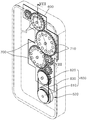
- the self-charging device for a smartphone according to another embodiment of the present invention may further include a coil pattern substrate 600 and a plurality of gears 700.
- the coil pattern substrate 600 is disposed in the accommodation space 120 of the charging cover 100, and a plurality of coils 610 are formed. In the coil pattern substrate 600, a plurality of coils may be formed to correspond to the plurality of gears 700. Coil 610 employed in another embodiment of the present invention is also preferably electrically connected to the circuit board 110.
- the plurality of gears 700 are disposed on the coil 610 of the coil pattern substrate 600 in the receiving space 120 of the charging cover 100, respectively, and are electrically connected to the rotating frame 520.
- a coil 610 and a magnet 710 for generating magnetic induction are provided and connected to each other to enable power transmission.
- the coil 610 of the coil pattern substrate 600 may be provided at the bottom of each gear 700 so as to interact with the magnet 710 provided in the gear 700. That is, when there are a plurality of gears 700, it is preferable that the coil 610 is also formed in a plurality.
- the power transmission means 800 may be provided in the rotating frame 520 and the neighboring gear 700.
- Power transmission means 800 is provided in the first rotating plate 810 is rotated provided in the rotating frame 520 and the gear provided in the gear 700 adjacent to the rotating frame 520
- the two rotating plates 820 are dynamically connected to each other by the cable 830.
- another power transmission means in another embodiment of the present invention is further provided with a gear 700 in the rotating frame 520, the gear of the rotating frame 520 may be connected to the adjacent gear 700 is powered dynamically have.
- the adjacent gear when the user rotates the rotating frame, the adjacent gear also rotates together, thereby producing electric power using the magnet and coil of the rotating frame and at the same time the magnet and coil pattern of the gear. Since power is simultaneously produced through the interaction between the coils of the substrate, there is an effect that can increase the power production efficiency.
Landscapes
- Engineering & Computer Science (AREA)
- Power Engineering (AREA)
- Signal Processing (AREA)
- Manufacturing & Machinery (AREA)
- Chemical & Material Sciences (AREA)
- Chemical Kinetics & Catalysis (AREA)
- Electrochemistry (AREA)
- General Chemical & Material Sciences (AREA)
- Life Sciences & Earth Sciences (AREA)
- Sustainable Development (AREA)
- Sustainable Energy (AREA)
- Charge And Discharge Circuits For Batteries Or The Like (AREA)
Abstract
La présente invention concerne un appareil de charge automatique de téléphone intelligent qui est utilisé en étant couplé à un côté formant l'extérieur d'un téléphone intelligent et qui est caractérisé en ce qu'il comprend : un couvercle de charge qui est couplé à un côté d'un téléphone intelligent et qui contient un espace de réception dans lequel peut être accueillie une carte de circuit imprimé ; et un cadre rotatif monté rotatif sur le couvercle de charge, et pourvu d'un aimant, qui provoque l'induction magnétique avec une bobine, de façon à pouvoir générer de l'énergie électrique par interaction avec la bobine installée dans l'espace de réception.
Applications Claiming Priority (2)
| Application Number | Priority Date | Filing Date | Title |
|---|---|---|---|
| KR1020160055564A KR101734319B1 (ko) | 2016-05-04 | 2016-05-04 | 스마트폰용 자가 충전 장치 |
| KR10-2016-0055564 | 2016-05-04 |
Publications (2)
| Publication Number | Publication Date |
|---|---|
| WO2017191972A2 true WO2017191972A2 (fr) | 2017-11-09 |
| WO2017191972A3 WO2017191972A3 (fr) | 2018-08-02 |
Family
ID=58739684
Family Applications (1)
| Application Number | Title | Priority Date | Filing Date |
|---|---|---|---|
| PCT/KR2017/004644 Ceased WO2017191972A2 (fr) | 2016-05-04 | 2017-05-02 | Appareil de charge automatique de téléphone intelligent |
Country Status (2)
| Country | Link |
|---|---|
| KR (1) | KR101734319B1 (fr) |
| WO (1) | WO2017191972A2 (fr) |
Cited By (1)
| Publication number | Priority date | Publication date | Assignee | Title |
|---|---|---|---|---|
| CN112290657A (zh) * | 2020-10-16 | 2021-01-29 | 歌尔科技有限公司 | 一种应急自发电的控制系统、智能穿戴设备、控制方法 |
Families Citing this family (1)
| Publication number | Priority date | Publication date | Assignee | Title |
|---|---|---|---|---|
| KR101966357B1 (ko) * | 2017-12-01 | 2019-04-05 | 남지현 | 휴대용 피젯 자가 발전기 |
Family Cites Families (5)
| Publication number | Priority date | Publication date | Assignee | Title |
|---|---|---|---|---|
| US20040204180A1 (en) * | 2002-11-05 | 2004-10-14 | Ming-Zhen Liao | Cellular phone with built-in generator |
| KR20060030663A (ko) * | 2004-10-06 | 2006-04-11 | 삼성전자주식회사 | 휴대 단말기의 배터리팩 자가충전장치 |
| US7608933B2 (en) * | 2005-10-31 | 2009-10-27 | Xiao (Charles) Yang | Method and structure for kinetic energy based generator for portable electronic devices |
| KR101626044B1 (ko) * | 2014-02-11 | 2016-06-08 | 이세현 | 자가 충전 기능을 구비한 모바일 기기 케이스 |
| KR101554109B1 (ko) * | 2014-08-21 | 2015-09-18 | 동양대학교 산학협력단 | 무선충전과 자가발전을 겸비한 모바일용 보호케이스 |
-
2016
- 2016-05-04 KR KR1020160055564A patent/KR101734319B1/ko not_active Expired - Fee Related
-
2017
- 2017-05-02 WO PCT/KR2017/004644 patent/WO2017191972A2/fr not_active Ceased
Cited By (2)
| Publication number | Priority date | Publication date | Assignee | Title |
|---|---|---|---|---|
| CN112290657A (zh) * | 2020-10-16 | 2021-01-29 | 歌尔科技有限公司 | 一种应急自发电的控制系统、智能穿戴设备、控制方法 |
| CN112290657B (zh) * | 2020-10-16 | 2022-04-26 | 歌尔科技有限公司 | 一种应急自发电的控制系统、智能穿戴设备、控制方法 |
Also Published As
| Publication number | Publication date |
|---|---|
| KR101734319B1 (ko) | 2017-05-15 |
| WO2017191972A3 (fr) | 2018-08-02 |
Similar Documents
| Publication | Publication Date | Title |
|---|---|---|
| JP3139151U (ja) | 携帯電話ケース | |
| JP5813135B2 (ja) | 移動充電器 | |
| WO2020067665A1 (fr) | Ensemble d'éléments de batterie, module de batterie comprenant ledit ensemble, bloc-batterie comprenant ledit module, et automobile comprenant ledit bloc-batterie | |
| WO2013129816A1 (fr) | Boîtier de terminal portable | |
| WO2015194714A1 (fr) | Batterie équipée d'une borne usb | |
| WO2017191972A2 (fr) | Appareil de charge automatique de téléphone intelligent | |
| WO2011155672A1 (fr) | Appareil d'éclairage portatif | |
| WO2026014891A1 (fr) | Berceau de dispositif de coloration capillaire | |
| WO2018070745A1 (fr) | Appareil de production d'énergie hybride de secours | |
| WO2022234938A1 (fr) | Dispositif d'alimentation électrique portable ayant une batterie amovible/remplaçable | |
| CN220510812U (zh) | 光伏太阳能充电宝 | |
| CN208548739U (zh) | 电磁感应式带双向无线充电的移动电源 | |
| WO2020122508A1 (fr) | Boîtier de stockage de terminal prenant en charge une fonction de charge sans fil | |
| WO2024019385A1 (fr) | Mini-générateur solaire hybride d'urgence | |
| CN208062892U (zh) | 一种无线充电移动电源 | |
| CN201663212U (zh) | 一种usb接头充电器 | |
| CN113036854A (zh) | 一种可拆卸电池的充放电装置 | |
| CN204835605U (zh) | 一种便携式户外太阳能电源 | |
| WO2017191971A2 (fr) | Appareil de charge automatique de téléphone intelligent | |
| CN206349770U (zh) | 一种充电装置及智能充电设备 | |
| TWM557478U (zh) | 行動電源 | |
| CN205319767U (zh) | 一种可以太阳能充电的移动电源 | |
| WO2015072590A1 (fr) | Générateur transportable | |
| WO2016021826A1 (fr) | Chargeur intégré pour téléphone mobile | |
| CN209001605U (zh) | 折叠共享充电装置 |
Legal Events
| Date | Code | Title | Description |
|---|---|---|---|
| NENP | Non-entry into the national phase |
Ref country code: DE |
|
| 121 | Ep: the epo has been informed by wipo that ep was designated in this application |
Ref document number: 17792874 Country of ref document: EP Kind code of ref document: A2 |
|
| 122 | Ep: pct application non-entry in european phase |
Ref document number: 17792874 Country of ref document: EP Kind code of ref document: A2 |