WO2017194500A2 - Appareil électroménager comprenant un bouton fermement monté sur le panneau - Google Patents
Appareil électroménager comprenant un bouton fermement monté sur le panneau Download PDFInfo
- Publication number
- WO2017194500A2 WO2017194500A2 PCT/EP2017/060991 EP2017060991W WO2017194500A2 WO 2017194500 A2 WO2017194500 A2 WO 2017194500A2 EP 2017060991 W EP2017060991 W EP 2017060991W WO 2017194500 A2 WO2017194500 A2 WO 2017194500A2
- Authority
- WO
- WIPO (PCT)
- Prior art keywords
- bearing
- insert
- handle
- household appliance
- shaft
- Prior art date
- Legal status (The legal status is an assumption and is not a legal conclusion. Google has not performed a legal analysis and makes no representation as to the accuracy of the status listed.)
- Ceased
Links
Images



Classifications
-
- G—PHYSICS
- G05—CONTROLLING; REGULATING
- G05G—CONTROL DEVICES OR SYSTEMS INSOFAR AS CHARACTERISED BY MECHANICAL FEATURES ONLY
- G05G1/00—Controlling members, e.g. knobs or handles; Assemblies or arrangements thereof; Indicating position of controlling members
- G05G1/08—Controlling members for hand actuation by rotary movement, e.g. hand wheels
- G05G1/10—Details, e.g. of discs, knobs, wheels or handles
- G05G1/12—Means for securing the members on rotatable spindles or the like
Definitions
- the present invention relates to a household appliance comprising a knob that is safely mounted to the panel.
- Household appliances for example cooking devices, dishwashers and in particular washers/dryers, comprise a panel, a control unit and one or more than one knob that enable the functions thereof to be monitored and controlled by the user.
- the knobs are directly attached to the shafts that are mechanically fastened to the switches on the control unit behind the panel by means of the housings on the panel or by means of an insert from the front of the panel.
- the shafts that are connected to the knobs also move and the functions at predetermined positions depending on the user preferences, for example functions like in which program the laundries should be washed, at which rpm the spin-drying should be performed or at which temperature the wash water should be used, are enabled to be selected.
- the knobs are mounted on the shaft that is connected to the control unit behind the panel from the front side of the panel for ease of production.
- the knob is mounted on the panel by means of clawed structures, some tolerances are needed to be taken into consideration so that the shaft and the knob can be easily borne to each other. Therefore, a gap should be left around the clawed structures. While facilitating the rotation of the knob, these gaps weaken the resistance of the knob against exterior impacts and cause the knob to be operated in a loose manner. According to the international standards, the knob should pass the impact test, therefore, it should be ensured that the knob does not dislodge due to the impact imparted.
- the aim of the present invention is the realization of a household appliance comprising a knob that is easily mounted and safely fixed onto the panel.
- the household appliance realized in order to attain the aim of the present invention, explicated in the first claim and the respective claims thereof, comprises a shaft that is borne by both an insert and a handle and that is mechanically connected to a control unit. Since the shaft fixes/locks the insert and the handle to each other, the insert and the handle cannot be separated without dislodging the shaft.
- a first bearing and a second bearing that are configured so as to allow the shaft to pass therethrough are provided, and the shaft is configured so as not to rotate in both bearings independently of the bearings.
- the insert and the handle are attached to each other so that the panel remains therebetween, as locking claws and locking protrusions engage with each other.
- the first bearing and the second bearing are positioned to be end to end and allow the shaft to pass therethrough. After passing through the bearings, the shaft prevents the insert and the handle from moving relative to each other.
- the shaft provides that the components interlock in an undetachable manner.
- the knob cannot be detached from the household appliance unless the shaft is dislodged from inside the knob.
- the dislodging of the knob under a load is prevented and both the perceptional quality is improved and the safety risk is eliminated.
- Figure 1 - is the general front view of the panel of a household appliance.
- Figure 2 – is the exploded cross-sectional view of the panel, the control unit, the shaft, the knob, the insert and the handle.
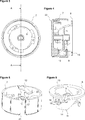
- Figure 3 — is the front view of the insert and the handle when attached to each other.
- Figure 4 is the view of the cross-section A– A in Figure 3.
- Figure 5 — is the perspective view of the handle.
- Figure 6 — is the perspective view of the insert.
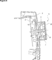
- Figure 7 — is the cross-sectional view of the insert and the handle that are fixed on the panel.
- Figure 8 — is the cross-sectional view of the insert, the handle and the shaft that are fixed on the panel.
- Figure 9 – is the front view of the handle when seated onto the insert.
- Figure 10 — is the front view of the insert and the handle when attached to each other.
- the household appliance (1) comprises a panel (2) enabling the user to monitor and control the functions of the household appliance (1); a control unit (3) disposed behind the panel (2); a shaft (4) that is connected to the control unit (3) and that enables user preferences to be transmitted to the control unit (3); a knob (5) that actuates the shaft (4); a handle (7) that is disposed on the knob (5); a housing (6) that is disposed on the panel (2) and wherein the knob (5) is placed,
- the knob (5) is mounted to the household appliance (1) in the following manner. First, the insert (8) is inserted into the housing (6) from behind the panel (2) and then, the handle (7) is pushed from the front of the panel (2) towards the part of the insert (8) projecting out of the housing (6) and the insert (8) and the handle (7) are mounted to each other so that the panel (2) remains therebetween. After the assembly, the insert (8) and the handle (7) are attached to each other by being rotated around the bearing axis. In this case, the first bearing (9) and the second bearing (10) complement each other ( Figure 3 and Figure 4). The shaft (4) is borne by being passed through the first bearing (9) and the second bearing (10). The second bearing (10) both bears the free end of the shaft (4) and surrounds the end thereof. By means of the shaft, the knob (5) cannot be dislodged from the panel without displacing the shaft (4) and the assembly of the knob (5) to the household appliance (1) is completed.
- the household appliance (1) comprises one or more than one locking claw (11) that is disposed on the insert (8) and that passes through the housing (6) when the insert (8) is fitted into the housing (6), and one or more than locking protrusion (12) that is disposed on the face of the handle (7) facing the panel (2) and with which the locking claws (11) engage.
- the handle (7) and the insert (8) engage with each other so that the panel (2) remains therebetween
- the handle (7) and the insert (8) are rotated around the bearing axis.
- the locking claws (11) on the insert (8) engage with the locking protrusion (12) on the handle (7) and thus the insert (8) and the handle (7) are attached to each other so that the panel (2) remains therebetween.
- the shaft (4) is not a full cylinder but in the form of a circle of which the cross-section is delimited by the diameter or the chord.
- the first bearing (9) and the second bearing (10) have forms corresponding to the form of the shaft (4).
- the shaft (4) when the shaft (4) is passed through the first and second bearings (9, 10) to be borne, the first bearing (9) and the second bearing (10) prevent the shaft (4) from rotating therein, thus the shaft (4) does not allow the insert (8) and the handle (7) to rotate relative to each other, hence does not allow the insert (8) and the handle (7) to move in opposite directions so as to be separated from each other.
- the household appliance (1) comprises a base (13) on the insert (8), that has a hole through which the shaft (4) passes, and at least two locking claws (11) that extend from the edge of the base (13) perpendicularly to the base (13) and that surround the first bearing (9), the length of the locking claws (11) being greater than the length of the first bearing (9).
- the first bearing (9) is located on a platform parallel to the base (13) while the first bearing (9) and the hole are coaxial.
- the household appliance (1) furthermore comprises an arm (14) that is disposed on the locking claw (11), that is almost L-shaped and that bears against the locking protrusion (12) when the insert (8) and the handle (7) are attached to each other, and a protrusion (15) that is disposed at the end of the arm (14).
- the household appliance (1) comprises a first inclined surface (16) and a recess (18) that are disposed on the locking claw (11) and that extend between the base (13) and the arm (14) ( Figure 6).
- the household appliance (1) furthermore comprises a skirt (21) that is disposed on the handle (7) and that surrounds the second bearing (10) located at the center of the handle (7).
- the household appliance (1) comprises a barrier (19) that is disposed on the locking protrusion (12) and that enters the recess (18) on the locking claw (11); a second inclined surface (17) that overlaps with the first inclined surface (16) on the locking claw (11), and a stopper (20) that goes over the protrusion (15) on the arm (14) and bears against the arm (14) ( Figure 5).
- first inclined surface (16) and the second inclined surface (17) are inclined at the same angle.
- first and second inclined surfaces (16 and 17) are seated onto each other in a flush manner.
- the insert (8) and the handle (7) cannot separate from each other without making a linear movement.
- the knob (5) is mounted to the household appliance (1) in the following manner.
- the insert (8) is inserted into the housing (6) from behind the panel (2).
- the insert (8) is moved inside the housing (6) until the base (13) bears against the rear wall of the panel (2) and the insert (8) is fixed onto the panel (2) such that the insert (8) can move only radially.
- the base (13) remains behind the panel (2) and the locking claws (11) are partially at the front side of the panel (2).
- the handle (7) is placed onto the insert (8) from the front of the panel (2).
- the locking claws (11) pass over the locking protrusions (12) and thus the handle (7) is seated onto the insert (8).
- first bearing (9) and the second bearing (10) abut to each other; however, both bearings (9, 10) does not fully overlap although the said components are coaxial.
- the chord of the first bearing (9) and the chord of the second bearing (10) are positioned so as to create an angle therebetween, thus preventing the shaft (4) from passing to the second bearing (10) from the first bearing (9) ( Figure 9). Since the first bearing (9) and the second bearing (10) do not overlap in this position, if the shaft (4) is inserted, the shaft (4) cannot be fully inserted into the first and second bearings (9 and 10) and be borne.
- the insert (8) and the handle (7) are rotated around the horizontal axis, thus enabling the locking claw (11) to be fully seated onto the locking protrusion (12).
- the locking protrusion (12) moves until the barrier (19) bears against the recess (18) on the locking claw (11).
- the barrier (19) bears against the recess (18) the first inclined surface (16) and the second inclined surface (17) bear against each other and the protrusion (15) goes over the stopper (20) and bears against the stopper (20).
- the locking claw (11) and the locking protrusion (12) prevent the insert (8) and the handle (7) from moving perpendicularly to the panel (2).
- the first bearing (9) and the second bearing (10) are aligned in an axial and end-to-end manner so as to allow the shaft (4) to pass therethrough.
- the first bearing (9) and the second bearing (10) complement each other ( Figure 10).
- the shaft (4) is borne by being smoothly passed through the first bearing (9) and the second bearing (10) and the assembly of the knob (5) onto the household appliance (1) is completed.
- the knob (5) is mounted on the part of the insert (8) that passes through the housing (6) to the front side of the panel (2) and the assembly of the knob (5) on the insert (8), hence on the panel (2) of the household appliance (1) is completed.
- the shaft (4) prevents the insert (8) and the handle (7) from rotating.
- the insert (8) and the handle (7) are prevented from rotating in opposite directions and being separated from each other.
- the shaft (4) borne by the first and second bearings (9 and 10) enables the insert (8) and the handle (7) to be locked to each other in an undetachable manner.
- the knob (5) cannot be detached from the panel (2) unless the shaft (4) is dislodged from the bearings (9 and 10).
- the household appliance (1) comprises a decorative element (22) mounted on the knob (5).
- the decorative element (22) can be produced as a single piece with the knob (5) or can be produced separately. In the case being produced separately, the decorative element (22) is mounted on the knob (5) by using various mechanical methods.
Landscapes
- Physics & Mathematics (AREA)
- General Physics & Mathematics (AREA)
- Engineering & Computer Science (AREA)
- Automation & Control Theory (AREA)
- Cookers (AREA)
- Mechanical Control Devices (AREA)
Abstract
La présente invention concerne un appareil électroménager (1) qui comprend un panneau (2) permettant à l'utilisateur de surveiller et de commander les fonctions de l'appareil électroménager (1) ; une unité de commande (3) disposée derrière le panneau (2) ; un arbre (4) qui est relié à l'unité de commande (3) et qui permet de transmettre les préférences de l'utilisateur à l'unité de commande (3) ; un bouton (5) qui actionne l'arbre (4) ; un boîtier (6) qui est disposé sur le panneau (2) et dans lequel est placé le bouton (5), et une pièce rapportée (8) et une poignée (7) qui sont fixées l'une à l'autre de façon que le panneau (2) reste entre celles-ci.
Applications Claiming Priority (2)
| Application Number | Priority Date | Filing Date | Title |
|---|---|---|---|
| TRA2016/06043 | 2016-05-09 | ||
| TR201606043 | 2016-05-09 |
Publications (2)
| Publication Number | Publication Date |
|---|---|
| WO2017194500A2 true WO2017194500A2 (fr) | 2017-11-16 |
| WO2017194500A3 WO2017194500A3 (fr) | 2018-01-04 |
Family
ID=58772851
Family Applications (1)
| Application Number | Title | Priority Date | Filing Date |
|---|---|---|---|
| PCT/EP2017/060991 Ceased WO2017194500A2 (fr) | 2016-05-09 | 2017-05-09 | Appareil électroménager comprenant un bouton fermement monté sur le panneau |
Country Status (1)
| Country | Link |
|---|---|
| WO (1) | WO2017194500A2 (fr) |
Cited By (1)
| Publication number | Priority date | Publication date | Assignee | Title |
|---|---|---|---|---|
| WO2020126468A1 (fr) * | 2018-12-19 | 2020-06-25 | Arcelik Anonim Sirketi | Appareil électroménager comprenant un élément décoratif pouvant être attaché/détaché par rapport au bouton |
Citations (2)
| Publication number | Priority date | Publication date | Assignee | Title |
|---|---|---|---|---|
| GB2040396A (en) | 1979-01-26 | 1980-08-28 | Breter Spa | Securing a control knob to a shaft |
| EP1829071A1 (fr) | 2004-12-24 | 2007-09-05 | Arçelik Anonim Sirketi | Appareil menager |
Family Cites Families (3)
| Publication number | Priority date | Publication date | Assignee | Title |
|---|---|---|---|---|
| DE2636920C3 (de) * | 1976-08-17 | 1981-11-05 | Agfa-Gevaert Ag, 5090 Leverkusen | Rastvorrichtung |
| NL177356C (nl) * | 1981-05-08 | 1985-09-02 | Nieaf Smitt B V | Knop voor een instelbaar apparaat. |
| DE29516875U1 (de) * | 1995-10-25 | 1996-05-30 | Siemens AG, 80333 München | Betätigungselement |
-
2017
- 2017-05-09 WO PCT/EP2017/060991 patent/WO2017194500A2/fr not_active Ceased
Patent Citations (2)
| Publication number | Priority date | Publication date | Assignee | Title |
|---|---|---|---|---|
| GB2040396A (en) | 1979-01-26 | 1980-08-28 | Breter Spa | Securing a control knob to a shaft |
| EP1829071A1 (fr) | 2004-12-24 | 2007-09-05 | Arçelik Anonim Sirketi | Appareil menager |
Cited By (1)
| Publication number | Priority date | Publication date | Assignee | Title |
|---|---|---|---|---|
| WO2020126468A1 (fr) * | 2018-12-19 | 2020-06-25 | Arcelik Anonim Sirketi | Appareil électroménager comprenant un élément décoratif pouvant être attaché/détaché par rapport au bouton |
Also Published As
| Publication number | Publication date |
|---|---|
| WO2017194500A3 (fr) | 2018-01-04 |
Similar Documents
| Publication | Publication Date | Title |
|---|---|---|
| EP3516103B1 (fr) | Appareil électroménager comprenant un bouton | |
| GB2130438A (en) | Rotary knob | |
| KR20160084073A (ko) | 의류처리장치 및 도어 | |
| KR20150005060A (ko) | 세탁기 | |
| WO2017152945A1 (fr) | Bouton rotatif à intégrité structurelle améliorée | |
| EP3037579B1 (fr) | Dispositif de verrouillage pour la porte de fermeture d'appareils électroménagers | |
| US10704177B2 (en) | Washing machine lid attachment | |
| WO2013098063A1 (fr) | Appareil domestique comprenant un panneau | |
| CN107849788B (zh) | 滚筒式洗衣机 | |
| EP3188880A1 (fr) | Verrouillage de sécurité pour appareils de cuisine | |
| WO2017044059A1 (fr) | Appareil électroménager comprenant un élément décoratif qui peut être attaché au bouton et détaché de celui-ci | |
| US10066334B2 (en) | Washing machine appliance with a door lock assembly | |
| US6422047B1 (en) | Washing machine with unbalance detection and control system | |
| WO2013098243A2 (fr) | Appareil électroménager | |
| EP3139394B1 (fr) | Appareil électroménager comprenant un bouton monté solidement sur le panneau | |
| EP3155160B1 (fr) | Appareil domestique comprenant une carte de circuits imprimés | |
| EP3447182B1 (fr) | Appareil ménager et procédé de fonctionnement associé | |
| WO2020126468A1 (fr) | Appareil électroménager comprenant un élément décoratif pouvant être attaché/détaché par rapport au bouton | |
| EP2764524B1 (fr) | Appareil électroménager | |
| RU2413043C2 (ru) | Стиральная или стиральная/сушильная машина с заградительным устройством | |
| EP3334320B1 (fr) | Appareil électroménager comprenant un bouton monté sur le panneau de commande | |
| WO2017134222A1 (fr) | Appareil électroménager comprenant un bouton transparent | |
| WO2014161793A1 (fr) | Appareil électroménager comprenant un verrou | |
| EP3347517B1 (fr) | Appareil électroménager dans lequel une fuite de liquide dans l'unité de commande est empêchée | |
| EP3440254B1 (fr) | Appareil électroménager à sécurité améliorée |
Legal Events
| Date | Code | Title | Description |
|---|---|---|---|
| NENP | Non-entry into the national phase in: |
Ref country code: DE |
|
| 121 | Ep: the epo has been informed by wipo that ep was designated in this application |
Ref document number: 17725887 Country of ref document: EP Kind code of ref document: A2 |
|
| 122 | Ep: pct application non-entry in european phase |
Ref document number: 17725887 Country of ref document: EP Kind code of ref document: A2 |