WO2017195301A1 - Dispositif de commande de moteur - Google Patents
Dispositif de commande de moteur Download PDFInfo
- Publication number
- WO2017195301A1 WO2017195301A1 PCT/JP2016/064039 JP2016064039W WO2017195301A1 WO 2017195301 A1 WO2017195301 A1 WO 2017195301A1 JP 2016064039 W JP2016064039 W JP 2016064039W WO 2017195301 A1 WO2017195301 A1 WO 2017195301A1
- Authority
- WO
- WIPO (PCT)
- Prior art keywords
- motor
- heat generation
- factor
- unit
- determination
- Prior art date
- Legal status (The legal status is an assumption and is not a legal conclusion. Google has not performed a legal analysis and makes no representation as to the accuracy of the status listed.)
- Ceased
Links
Images



Classifications
-
- H—ELECTRICITY
- H02—GENERATION; CONVERSION OR DISTRIBUTION OF ELECTRIC POWER
- H02P—CONTROL OR REGULATION OF ELECTRIC MOTORS, ELECTRIC GENERATORS OR DYNAMO-ELECTRIC CONVERTERS; CONTROLLING TRANSFORMERS, REACTORS OR CHOKE COILS
- H02P29/00—Arrangements for regulating or controlling electric motors, appropriate for both AC and DC motors
- H02P29/60—Controlling or determining the temperature of the motor or of the drive
-
- H—ELECTRICITY
- H02—GENERATION; CONVERSION OR DISTRIBUTION OF ELECTRIC POWER
- H02P—CONTROL OR REGULATION OF ELECTRIC MOTORS, ELECTRIC GENERATORS OR DYNAMO-ELECTRIC CONVERTERS; CONTROLLING TRANSFORMERS, REACTORS OR CHOKE COILS
- H02P29/00—Arrangements for regulating or controlling electric motors, appropriate for both AC and DC motors
- H02P29/60—Controlling or determining the temperature of the motor or of the drive
- H02P29/62—Controlling or determining the temperature of the motor or of the drive for raising the temperature of the motor
Definitions
- the present invention relates to a motor control device that controls a motor with a cooling device.
- Motors are widely used in industrial devices in general, and a method of forced cooling by a cooling device is used in many motors in order to suppress the heat generation of the motors.
- a method of forcibly cooling the motor by attaching a cooling fan to the motor and sending cooling air to the motor.
- the motor is forcibly cooled by forming a refrigerant flow path in the motor body and circulating the refrigerant in the flow path with a pump while cooling the refrigerant with an oil cooler.
- the devices associated with the motor for forcibly cooling the motor are collectively referred to as a cooling device.
- the operating conditions of the motor are set to conditions that place a high load on the motor for the purpose of maximizing the production efficiency, and therefore operating conditions that apply a higher load than the cooling capacity of the cooling device are set.
- the motor may generate heat.
- dust adheres to the cooling device or the flow path is clogged, the cooling capacity is reduced, and the motor may generate heat even under operating conditions that are not inherently a problem. If the motor suddenly generates heat or the temperature of the motor after heat generation remains high, the original performance of the motor cannot be exhibited. Furthermore, the life of the motor is shortened, causing unexpected failures. For this reason, when the motor generates heat, it is necessary to detect the heat generation at an early stage and take appropriate countermeasures according to the heat generation factor.
- Patent Document 1 discloses a temperature rise amount caused by acceleration / deceleration of the spindle motor and a temperature rise amount caused by cutting during constant rotation, respectively. A method for changing the operating conditions is also described.
- the method of Patent Document 1 is a method for determining heat generation due to incompatibility of motor operating conditions, and when the heat is generated by factors other than motor operating conditions, the factors cannot be determined. Specifically, even when the motor is not properly cooled due to a decrease in the cooling capacity of the cooling device and the motor temperature rises, the method of Patent Document 1 performs the same operation as when the cooling device is normal. Originally, it is necessary to change the operation of the apparatus in accordance with a decrease in the cooling capacity of the cooling apparatus, but in the method of Patent Document 1, all the heat generation factors are regarded as nonconformity of the operating conditions.
- the method of Patent Document 1 determines a heat generation factor after fixing the heat generation factor to one in advance, and performs a process of changing the operation. Yes. That is, the determination assuming a plurality of heat generation factors is not performed. Examples of countermeasures when the motor generates heat include changing operating conditions, cleaning the cooling device, and replacing the motor, but these work differently and have different effects for each motor heat factor. . For this reason, if a measure is taken without specifying a factor, there is a possibility that another measure will be taken because the measure is not effective even though work time has been spent. In this case, there is a problem that work for searching for a heat generation factor and work for examining countermeasures against the heat generation factor are newly required, resulting in a decrease in work efficiency.
- This invention is made in view of the above, Comprising: It aims at obtaining the motor control apparatus which can determine a several factor with respect to the heat_generation
- the present invention provides a motor control device that controls a motor with a cooling device, an acquisition unit that acquires the temperature of the motor, a motor that is driven, A drive control unit that outputs the operation condition as an operation information signal.
- the present invention further includes a factor determination unit that determines that one or more of the plurality of heat generation factors are the motor heat generation factors based on the motor temperature and the operation information signal.
- the motor control device has an effect that a plurality of factors can be determined for the heat generation of the motor with the cooling device.
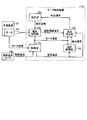
- FIG. 1 is a block diagram showing a configuration of a motor control device according to a first embodiment of the present invention.
- FIG. 6 is a diagram showing an example of display on the display device according to the first embodiment.
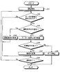
- 1 is a flowchart showing processing executed by the motor control device according to the first embodiment;
- FIG. 3 is a block diagram showing a configuration of a motor control device according to a second embodiment of the present invention.
- 10 is a flowchart showing processing executed by the motor control device according to the third embodiment.
- 10 is a flowchart showing processing executed by the motor control device according to the fourth embodiment.
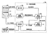
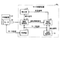
- FIG. 1 is a block diagram showing a configuration of a motor control device 10 according to the first embodiment of the present invention.
- the motor control device 10 is connected to the motor 20 provided with the cooling device 21 and the display device 30 to control the motor 20. Further, the motor control device 10 acquires the motor temperature, which is the temperature of the motor 20, and displays information related to the determination of the cause of the heat generation of the motor 20 on the display device 30 when the heat generation of the motor 20 is detected.
- specific examples of the cooling device 21 are a cooling fan, an oil cooler for water cooling or oil cooling, and a pump.
- the cooling device 21 always operates to cool the motor 20 regardless of the rotation or stop of the motor 20.
- a specific example of the display device 30 is a screen display device installed near the motor control device 10 or an information terminal such as a personal computer or a tablet that exists in a remote place via a communication line.
- the motor control device 10 supplies a current to the motor 20 to drive the motor 20 and acquires a driving state including the current, output, speed, and position of the motor 20 and the motor temperature.
- the motor control device 10 includes an acquisition unit 11 that acquires a motor temperature, a drive control unit 12 that drives the motor 20, a temperature monitoring unit 13 that monitors the motor temperature, and a factor determination unit that determines a factor of heat generation of the motor 20. 14 and a display unit 15 that outputs a display signal to the display device 30.
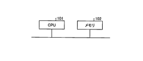
- FIG. 2 is a diagram illustrating a hardware configuration when the functions of the motor control device according to the first to fourth embodiments are realized by a computer.
- the function of the motor control device 10 is realized by a computer
- the function of the motor control device 10 is realized by a CPU (Central Processing Unit) 101 and a memory 102 as shown in FIG.
- the function of the motor control device 10 is realized by software, firmware, or a combination of software and firmware.
- Software or firmware is described as a program and stored in the memory 102.
- the CPU 101 reads out and executes a program stored in the memory 102, thereby realizing functions of each unit of the motor control device 10.
- the motor control device 10 includes a memory 102 for storing a program in which the step of executing the operation of the motor control device 10 is executed as a result when the function of each unit is executed by the computer. .
- These programs can also be said to cause a computer to execute the procedure or method of the motor control device 10.
- the memory 102 also stores an operation program for the motor 20.
- the memory 102 is a RAM (Random Access Memory), a ROM (Read Only Memory), a flash memory, an EPROM (Erasable Programmable Read Only Memory), an EEPROM (Electrically Erasable Programmable Memory).
- Discs, flexible discs, optical discs, compact discs, mini discs, DVDs (Digital Versatile Disks) are applicable.
- the acquisition unit 11 is connected to a sensor that measures the temperature of the motor 20, and acquires the motor temperature at each time.
- the acquisition unit 11 outputs the acquired motor temperature to the temperature monitoring unit 13 and the factor determination unit 14.
- the drive control unit 12 is connected to the motor 20 and drives the motor 20.
- operating conditions of the motor 20 are set in advance by an operating program.
- the drive control unit 12 controls the motor 20 so that the motor 20 is operated based on the set operation condition.
- the drive control unit 12 monitors the driving state of the motor 20.
- the drive control unit 12 outputs the drive state of the motor 20 and the operation conditions of the motor 20 set in the drive control unit 12 to the factor determination unit 14 as an operation information signal.
- the operation of the motor 20 represents a series of operations of the motor 20 including driving and temporary stop of the motor 20. Therefore, the operating conditions of the motor 20 represent conditions such as output, current, acceleration, acceleration / deceleration time constant, and operating time determined by a series of drive commands and stop commands for causing the motor 20 to perform a target operation.
- the temperature monitoring unit 13 monitors the motor temperature of the operating motor 20 acquired by the acquiring unit 11 and outputs a detection signal to the factor determining unit 14 when heat generation of the motor 20 is detected.
- a heat generation detection threshold is set in the temperature monitoring unit 13.
- the heat generation detection threshold is a value for detecting the possibility of abnormal heat generation of the motor 20, and is a value set on the basis of heat generation during a reference operation that is considered to be normal.
- the temperature monitoring unit 13 calculates an increase amount from the start of operation of the motor temperature of the motor 20 during operation, and compares it with the heat generation detection threshold value. When the change amount of the motor temperature exceeds the heat generation detection threshold, the temperature monitoring unit 13 determines that the motor 20 has generated heat, and outputs a detection signal to the factor determination unit 14.
- the heat generation detection of the motor 20 it may be detected in comparison with a threshold value by using a time change rate of the motor temperature in addition to the increase amount of the motor temperature. Further, as a determination method other than the above, there is a method of determining that the heat generation of the motor 20 is caused when the temperature variation with respect to the temperature of the motor 20 during the reference operation exceeds a predetermined amount.
- the factor determination unit 14 determines a factor of heat generation of the motor 20 based on the motor temperature and the operation information signal, and information on the internal state of the factor determination unit 14. Is output to the display unit 15.
- the internal state of the factor determination unit 14 includes countermeasures according to the determination status, determination result, and heat generation factor in the factor determination unit 14.
- the factor determination unit 14 determines the factor of heat generation of the motor 20 detected by the temperature monitoring unit 13 based on the operation information signal output from the drive control unit 12 and the motor temperature acquired by the acquisition unit 11. Below, the determination method for every determination result in the factor determination part 14 is described.
- the factor determination unit 14 determines whether or not the operation condition set by the drive control unit 12 is incompatible with the specification of the motor 20 based on the driving state of the motor 20 during operation.
- the factor determination unit 14 calculates a driving condition determination time width based on the driving information signal.
- the operation condition determination time width is a time width for determining an operation condition for the motor 20, and is a value obtained by estimating the time for the motor 20 to execute the operation described in the operation program based on the operation condition. A fixed value may be set for the operating condition determination time width.
- the operating condition determination threshold is preset in the factor determination unit 14.
- the operation condition determination threshold is a reference value for determining whether or not the operation of the motor 20 in the operation condition determination time width is incompatible with the specification of the motor 20.
- the factor determination unit 14 sets the cause of heat generation of the motor 20 by the drive control unit 12 “ It is determined that the operation condition is not met.
- the output of the motor 20 is a physical quantity corresponding to the product of the rotation speed and torque of the motor 20.
- a plurality of sets of operating condition determination time widths and operating condition determination threshold values can be set. In this case, when the average value of the output of the motor 20 calculated from any one of the operating condition determination time widths is equal to or greater than the operating condition determination threshold corresponding to the operating condition determination time width, it is determined as “nonconformity of operating conditions”. To do. Note that torque current during operation of the motor 20 may be used for determination instead of the output of the motor 20.
- the factor determination unit 14 determines whether or not the cooling capacity of the cooling device 21 has decreased based on the motor temperature when the motor 20 is stopped.
- a cooling device determination time width and a cooling device determination threshold are set in advance.
- the cooling device determination time width is a time width required for determining a decrease in cooling capacity.
- the cooling device determination threshold value is a reference value for determining whether or not the cooling capacity of the cooling device 21 is lowered from the temperature change of the motor 20 in the cooling device determination time width.
- the factor determining unit 14 When the motor 20 is in a temporarily stopped state or the operation end state, the factor determining unit 14 generates heat generated by the motor 20 if the amount of decrease in the motor temperature when the cooling device determination time has elapsed is equal to or less than the cooling device determination threshold. It is determined that the factor is “decrease in cooling capacity” of the cooling device 21.
- the time change rate of the motor temperature may be determined by comparing with a threshold value.
- a determination method may be used as a determination method other than the above.
- the factor determination unit 14 determines that the cause of the heat generation of the motor 20 is “other factors” when the cause of the heat generation of the motor 20 is neither “nonconformity of operating conditions” nor “decrease in cooling capacity” of the cooling device 21.
- the display unit 15 outputs information related to the determination of the heat generation factor of the motor 20 to the display device 30 as a display signal based on the determination signal input from the factor determination unit 14.
- the display signal includes information indicating that the detection signal is input from the temperature monitoring unit 13.
- the display signal is a signal including at least one of information on the determination status in the factor determination unit 14, information on the determination result in the factor determination unit 14, and information on countermeasures according to the heat generation factor.
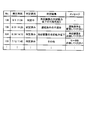
- FIG. 3 is a diagram illustrating an example of display on the display device 30 according to the first embodiment.
- the heat generation detection number “No.”, the heat generation detection “occurrence time”, the factor “judgment status”, the factor “judgment result”, and the “message” indicating the countermeasures for each factor Is displayed.
- the “occurrence time” of heat generation detection is the time when the factor determination unit 14 receives the detection signal from the temperature monitoring unit 13.
- the “determination status” of the factor is a determination status inside the factor determination unit 14, and is a state of whether the determination is “determined” or the determination is “determined”. Represents.
- the “determination result” of the factor represents the result of the factor determination determined by the factor determination unit 14.
- the “message” indicating the countermeasure for each factor represents a countermeasure to be taken by the worker according to the result determined by the factor determination unit 14.
- “determination status” of “No. 136”, which is the latest heat generation, is displayed as “determining”. Therefore, the “determination result” may be “the cooling capacity of the cooling device may be reduced. Is displayed. Since the determination is not finalized, the “message” is not displayed. Before “No. 135”, “Determined” is displayed as “Decision status”, so “Decision result” is displayed as “Non-conformance of operating conditions”, “Cooling capacity of cooling device” or “Other” Has been.
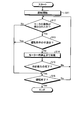
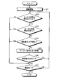
- FIG. 4 is a flowchart illustrating processing executed by the motor control device 10 according to the first embodiment.
- step S11 the drive control unit 12 causes the motor 20 to start operation based on the operation conditions.
- step S12 the temperature monitoring unit 13 determines whether or not heat generation of the motor 20 during operation is detected.
- step S12: Yes the process proceeds to step S13.
- step S12: No the process proceeds to step S16.
- step S ⁇ b> 13 the factor determination unit 14 determines whether or not the cause of heat generation of the motor 20 is incompatibility with the operation condition in the drive control unit 12 based on the driving state of the motor 20.
- step S13: Yes the process proceeds to step S16.
- step S13: No the factor determination part 14 determines that it is not non-conformity of driving conditions.
- step S14 the factor determination unit 14 waits until the motor 20 temporarily stops to determine whether or not the cooling capacity of the cooling device 21 has decreased.
- step S15 the factor determination unit 14 determines whether the cause of heat generation of the motor 20 is a decrease in the cooling capacity of the cooling device 21 based on the motor temperature while the motor 20 is temporarily stopped.
- step S15: Yes the process proceeds to step S16.
- step S15: No it is determined that the cause of heat generation of the motor 20 is another factor, and the process returns to step S12. The presence or absence of heat generation is determined again.
- step S16 the drive control unit 12 determines whether or not to end the operation of the motor 20.
- step S16: Yes the motor control apparatus 10 complete
- step S16: No the process returns to step S12, and the temperature monitoring unit 13 determines again whether or not the motor 20 generates heat.
- step S15 the factor determination unit 14 determines whether or not the cooling capacity of the cooling device 21 has decreased during the temporary stop of the motor 20, but the motor 20 is temporarily stopped longer than the cooling device determination time width during operation. If not, the next process is performed without determining in step S15. That is, a branch is provided before step S15. In this branch, when the motor 20 does not pause for a longer time than the cooling device determination time width during operation, the factor determination unit 14 performs a process of determining a decrease in cooling capacity after the operation in step S16. When the motor 20 is temporarily stopped longer than the cooling device determination time width during operation, the factor determination unit 14 performs a process of determining a decrease in cooling capacity during the temporary stop according to FIG.
- the factor determination unit 14 determines the heat generation factor of the motor 20.
- the factor determination unit 14 outputs to the display device 30 a “message” indicating the “determination status”, “determination result”, and “measurement result” of the factor based on the analysis. That is, when the heat generation of the motor 20 is detected, the motor control device 10 determines that the heat generation of the motor 20 has been detected, the determination status and determination result related to the factor determination, and the countermeasure measures according to the heat generation factor. To present.
- the motor control device 10 when the heat generation of the motor 20 is detected, one or more of the plurality of heat generation factors are determined based on the temperature information or the operation information. Since it can determine as a heat_generation
- the time required for searching for the heat generation factor and the time for examining the countermeasure for the heat generation factor can be reduced, so that the operator can take appropriate measures according to the heat generation factor. Can be taken immediately. Therefore, the work efficiency of the worker can be improved.
- information related to factor determination is centrally displayed in a table format, but the display method is not limited to the format shown in FIG.
- the display method of the determination result of the factor may be in a form of arranging by the determination result.
- the display unit 15 also shows the motor control device 10, the motor 20, and the cooling device 21 on the screen of the display device 30, and when the heat generation of the motor 20 is detected and the factor determination is completed, the heat generation factor A method may be used in which a message is written with emphasis on the elements that have become.
- the countermeasure message for the determined heat generation factor is not limited to the message content of FIG. 3, and a different message may be displayed as appropriate according to the heat generation factor.
- the currently set operating conditions and the recommended operating conditions may be displayed together.
- a message “Replace the cooling device” may be displayed.
- a message “Please replace the motor” may be displayed.
- the process of determining the factors in the order of determining whether or not the operating conditions are incompatible first and then determining whether or not the cooling capacity is reduced is shown.
- the determination of the heat generation factor by the motor control device 10 according to the first embodiment is not limited to the order shown in FIG. 4, and the order of determination may be reversed.
- the determination result of the heat generation factor does not need to be one, and the process proceeds to step S14 regardless of the determination result in step S13, and it is also determined whether or not the cooling capacity is reduced. It may be determined that a plurality of heat generation factors such as “decrease in cooling capacity” have occurred.
- FIG. FIG. 5 is a block diagram showing a configuration of the motor control device 10b according to the second embodiment of the present invention.
- symbol is attached
- an ambient temperature sensor 40 is added compared to FIG.
- the ambient temperature sensor 40 is connected to the motor control device 10b.
- the ambient temperature sensor 40 is a sensor for measuring the ambient temperature of the motor 20.
- the acquisition unit 11b is connected to a sensor that measures the temperature of the motor 20 and the ambient temperature sensor 40, and acquires the motor temperature and ambient temperature at each time.
- the acquisition unit 11b outputs the acquired motor temperature to the temperature monitoring unit 13 and the factor determination unit 14b. Furthermore, the acquisition unit 11b outputs the acquired ambient temperature to the factor determination unit 14b.
- the factor determination unit 14b determines a factor of heat generation of the motor 20 based on the motor temperature, the ambient temperature, and the operation information signal, and the factor determination unit 14b A determination signal including information on the internal state is output to the display unit 15b.
- the internal state of the factor determination unit 14b includes countermeasures according to the determination status, determination result, and heat generation factor in the factor determination unit 14b.
- the factor determination unit 14b determines a factor of heat generation of the motor 20 detected by the temperature monitoring unit 13 based on the operation information signal output from the drive control unit 12 and the motor temperature acquired by the acquisition unit 11b. Below, the determination method corresponding to each determination result in the factor determination part 14b is described.
- the factor determination unit 14b determines whether the ambient environment of the motor 20 has changed based on the input ambient temperature.
- an ambient environment determination threshold value that is a reference for determining that the ambient temperature is a factor of heat generation of the motor 20 is set in advance.
- the factor determination unit 14b performs “incompatibility of operating conditions” for the motor 20 and the “decrease in cooling capacity” of the cooling device 21 executed by the factor determination unit 14 in the first embodiment, “Change” and “deterioration” of the main body of the motor 20 are determined. If the ambient temperature is equal to or higher than the ambient environment determination threshold, it is determined that the cause of heat generation of the motor 20 is an increase in ambient temperature due to the “change in ambient environment” of the motor 20.
- the factor determination unit 14 b Judged to be “deteriorated”.
- the display unit 15b outputs information related to the determination of the cause of heat generation of the motor 20 to the display device 30 as a display signal based on the determination signal input from the factor determination unit 14b.
- the display signal includes the fact that the temperature monitoring unit 13 detects the heat generation of the motor 20, the determination status in the factor determination unit 14b, the determination result in the factor determination unit 14b, and a countermeasure measure corresponding to the heat generation factor. .
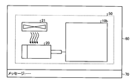
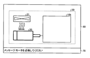
- FIGS. 6 to 8 are diagrams illustrating examples of display on the display device 30 according to the second embodiment.
- the schematic diagram column 60 showing the outline of the motor control device 10b, the main body of the motor 20, the cooling device 21, and the motor ambient environment 50, which are the main causes of the heat generation of the motor 20, and the determination status And a message column 70 for displaying a message for the worker according to the determination result.
- FIG. 6 is a diagram illustrating an example of a display when the heat generation of the motor 20 is not detected
- FIG. 7 is a diagram illustrating an example of a display during the factor determination when the heat generation of the motor 20 is detected
- FIG. 8 is a diagram illustrating an example of a display when the heat generation of the motor 20 is detected and the factor has been determined.
- the main body of the motor 20 in the schematic diagram column 60 Is displayed with emphasis, and a message “Please check the motor” is displayed in the message column 70, which is a measure to be taken when the heat generation factor is deterioration of the main body of the motor 20.
- the message displayed when the factor determination is completed depends on the factor determination result.
- FIG. 9 is a flowchart illustrating processing executed by the motor control device 10b according to the second embodiment.
- step S21 the drive control unit 12 causes the motor 20 to start operation based on the operation conditions.
- step S22 the temperature monitoring unit 13 determines whether or not heat generation of the motor 20 during operation is detected.
- step S22: Yes the process proceeds to step S23.
- step S22: No the process proceeds to step S27.
- step S23 the factor determination unit 14b determines whether the cause of heat generation of the motor 20 is a change in the ambient environment of the motor 20 based on the ambient temperature.
- step S23: Yes the process proceeds to step S27.
- step S24 the process proceeds to step S24.
- step S ⁇ b> 24 the factor determination unit 14 b determines whether the cause of heat generation of the motor 20 is incompatibility with the operation conditions in the drive control unit 12 based on the driving state of the motor 20.
- step S24: Yes the process proceeds to step S27.
- step S24: No the process proceeds to step S25.
- step S25 the factor determination unit 14b waits until the motor 20 is temporarily stopped in order to determine whether or not the cooling capacity of the cooling device 21 has decreased.
- step S26 the factor determination unit 14b determines whether the cause of heat generation of the motor 20 is a decrease in the cooling capacity of the cooling device 21 based on the motor temperature while the motor 20 is temporarily stopped.
- step S26: Yes the process proceeds to step S27.
- step S26: No the factor determination unit 14b determines that the cause of heat generation of the motor 20 is “deterioration” of the main body of the motor 20, and step S22.
- step S5 it is determined again whether the motor 20 is generating heat.
- step S27 the drive control unit 12 determines whether or not to end the operation of the motor 20.
- step S27: Yes the process ends.
- step S27: No the drive control part 12 continues the driving
- step S26 the factor determination unit 14b determines whether or not the cooling capacity of the cooling device 21 has decreased during the temporary stop of the motor 20, but the motor 20 is temporarily stopped longer than the cooling device determination time width during operation. If not, the next process is performed without determining in step S26. That is, a branch is provided before step S26. In this branch, when the motor 20 does not pause for a longer time than the cooling device determination time width during operation, the factor determination unit 14b executes processing for determining a decrease in cooling capacity after the operation in step S27. When the motor 20 is temporarily stopped longer than the cooling device determination time width during operation, the factor determination unit 14b performs a process of determining a decrease in cooling capacity during the temporary stop according to FIG.
- the motor control device 10b according to the second embodiment is configured to acquire the ambient temperature from the ambient temperature sensor 40 in addition to the configuration of the motor control device 10 according to the first embodiment. For this reason, the motor control device 10b according to the second embodiment has the following effects.
- the motor control device 10b acquires the ambient temperature, in addition to the determination result obtained by the factor determination performed in the first embodiment, the “change in ambient environment” of the motor 20 and the “deterioration” of the main body of the motor 20 are obtained.
- the determination can be made by including the determination result of the cause of the heat generation of the motor 20. As a result, more detailed determination can be made as compared with the motor control device 10 according to the first embodiment. Therefore, the worker can take more appropriate countermeasures based on the display on the display device 30.
- the factor determination unit 14b performs the determination of the heat generation factor of the motor 20 from the heat generation factor that is easy to determine without stopping the motor 20 being operated unnecessarily. The time required for the entire determination can be made as short as possible.
- the display method is not limited to the formats in FIG. 6 to FIG.
- the display method may be a table format as shown in FIG. 3 described in the first embodiment.
- the countermeasure message for the determined heat generation factor is not limited to the content of the message shown in FIG. 8, and a different message may be displayed as appropriate according to the heat generation factor. Specifically, instead of displaying “Please check the motor”, the message “Replace the motor” may be used. Further, instead of displaying “Please check the surrounding environment”, a message “Please improve the cooling capacity of the cooling device” may be used.
- the factors are determined in the order of first determining whether or not the ambient environment of the motor 20 has changed, then determining whether or not the operating condition is incompatible, and then determining whether or not the cooling capacity has decreased.
- the process of judging was shown.
- the determination of the heat generation factor by the motor control device 10b according to the second embodiment is not limited to the order shown in FIG. 9, and the determination order may be changed.
- the determination result of the heat generation factor is not necessarily one, and it may be determined that a plurality of heat generation factors are generated by executing step S24 regardless of the determination result in step S23. That is, the cause of the heat generation of the motor 20 is any one or more of “change in ambient environment”, “nonconformity of operating conditions” and “decrease in cooling capacity”, or “deterioration” of the main body of the motor 20. You may judge.
- FIG. 10 is a block diagram showing a configuration of a motor control device 10c according to the third embodiment of the present invention.
- symbol is attached
- a correction unit 16 is provided instead of the display unit 15 as a component in the motor control device 10 c. Therefore, the display device 30 is not shown in FIG.
- the function of the motor control device 10c is realized by a computer
- the function of the motor control device 10c is realized by the CPU 101 and the memory 102 as shown in FIG.
- the operations of the acquisition unit 11c and the drive control unit 12c are different from those in the first embodiment, and a correction unit 16 is newly added. Therefore, the following description will focus on the portions related to these operations. To do.
- the acquisition unit 11c is connected to a sensor that measures the temperature of the motor 20, and acquires the motor temperature at each time.
- the acquisition unit 11c outputs the acquired motor temperature to the temperature monitoring unit 13, the factor determination unit 14, and the drive control unit 12c.
- the drive control unit 12 c is connected to the motor 20 and drives the motor 20.
- the operation condition of the motor 20 is set in advance by an operation program, and the drive control unit 12c controls the motor 20 so that the motor 20 operates based on the operation condition.
- the drive control unit 12c monitors the drive state of the motor 20 and the motor temperature.
- An overload determination threshold and an overheat determination threshold are set in the drive control unit 12c.
- the overload determination threshold and the overheat determination threshold are values determined by the specifications of the motor 20 regardless of the operating conditions, and are thresholds for protecting the motor 20 from overload and overheating.
- the drive control unit 12c determines that the motor 20 is overloaded and outputs a signal for stopping the motor 20.
- the motor temperature exceeds the overheat determination threshold
- the drive control unit 12c determines that the motor 20 is overheated and outputs a signal for stopping the motor 20.
- the drive control unit 12c determines the overload using the instantaneous value of the output of the motor 20, but the time width for the overload determination is preset in the drive control unit 12c from the specifications of the motor 20.
- the drive control unit 12c may obtain an average value or an accumulated value of the output of the motor 20 in this time width and use it for the determination. Further, the drive control unit 12 c may use the current of the motor 20 for determination instead of the output of the motor 20.
- the overload determination and overheat determination determined by the drive control unit 12c are determinations for protecting the motor 20 from overload and overheat regardless of the operation conditions. Therefore, the determination purpose is different from the determination of heat generation that the temperature monitoring unit 13 performs based on the comparison with the reference operation.
- the drive state monitored by the drive control unit 12c and the operation conditions set in the drive control unit 12c are output to the factor determination unit 14 as an operation information signal. Furthermore, when the correction signal is input from the correction unit 16, the drive control unit 12c changes at least one of the operation condition, the overload determination threshold value, or the overheat determination threshold value.
- the correction unit 16 outputs a correction signal to the drive control unit 12 c based on the determination signal input from the factor determination unit 14.
- the content of the correction signal varies depending on the determination result of the factor determination unit 14, that is, the heat generation factor of the motor 20.
- the correction signal is a signal for changing the operating conditions. Specifically, it is a signal for instructing at least one of processing for reducing output, processing for reducing current, processing for reducing acceleration, and processing for increasing the acceleration / deceleration time constant.
- the correction signal decreases the overload determination threshold or the overheat determination threshold set in the drive control unit 12c to the drive control unit 12c. Signal.
- the correction signal is a signal for causing the drive control unit 12 c to stop the motor 20.
- FIG. 11 is a flowchart illustrating processing executed by the motor control device 10c according to the third embodiment.
- step S31 the drive control unit 12c causes the motor 20 to start operation based on the operation conditions.
- step S32 the temperature monitoring unit 13 determines whether or not heat generation of the motor 20 during operation is detected.
- step S32: Yes the process proceeds to step S33.
- step S32: No the process proceeds to step S39.
- step S33 the factor determination unit 14 determines whether or not the cause of heat generation of the motor 20 is an incompatibility with the operation condition in the drive control unit 12c based on the driving state of the motor 20.
- step S33: Yes the process proceeds to step S34.
- step S33: No the process proceeds to step S35.
- step S34 since it was determined in step S33 that the heat generation factor of the motor 20 is incompatible with the operating conditions, the correction unit 16 outputs a correction signal for changing the driving conditions to the drive control unit 12c, and the drive control unit 12c changes an operating condition based on a correction signal. After step S34 ends, the process proceeds to step S39.
- step S35 the factor determination unit 14 waits until the motor 20 temporarily stops to determine whether or not the cooling capacity of the cooling device 21 has decreased.
- step S36 the factor determination unit 14 determines whether the cause of heat generation of the motor 20 is a decrease in the cooling capacity of the cooling device 21 based on the motor temperature while the motor 20 is temporarily stopped.
- step S36: Yes the process proceeds to step S37.
- step S36: No the process proceeds to step S38.
- step S37 since it is determined in step S36 that the heat generation factor of the motor 20 is a decrease in the cooling capacity of the cooling device 21, the correction unit 16 drives a correction signal for changing the overload determination threshold value or the overheat determination threshold value.
- the output to the control unit 12c, and the drive control unit 12c changes at least one of both thresholds based on the correction signal.
- step S38 since it is determined that the heat generation factor of the motor 20 is not “nonconformity of operating conditions” and “decrease in cooling capacity” of the cooling device 21, it is determined that it is “other factors”. 20 is stopped and driving
- step S39 the drive control unit 12c determines whether or not to end the operation of the motor 20.
- step S39: Yes the process ends.
- step S39: No the drive control part 12c continues the driving
- step S36 the factor determination unit 14 determines whether or not the cooling capacity of the cooling device 21 has decreased during the temporary stop of the motor 20, but the motor 20 is temporarily stopped longer than the cooling device determination time width during operation. If not, the next process is performed without determining in step S36. That is, a branch is provided before step S36. In this branch, when the motor 20 does not pause for a longer time than the cooling device determination time width during operation, the factor determination unit 14 performs a process for determining a decrease in cooling capacity after the operation in step S39, and further the cooling capacity In the case where it is determined that the value is lower, the drive control unit 12c executes a process of changing the threshold value.
- the factor determination unit 14 performs a process of determining a decrease in cooling capacity during the temporary stop according to FIG.
- the drive control unit 12c decreases the overload determination threshold or the overheat determination threshold in advance during the next operation. Start operation in the state.
- the factor determination unit 14 determines the heat generation factor of the motor 20, and the determination result. This is a configuration for outputting a correction corresponding to the drive control unit 12c.
- the motor control device 10c When it is determined that the heat generation factor of the motor 20 is “nonconformity of operation conditions”, the motor control device 10c according to the third embodiment suppresses the heat generation of the motor 20 itself because the operation conditions of the motor 20 are changed. it can.
- the drive control unit 12 c decreases the overload determination threshold value or the overheat determination threshold value. That is, the drive control unit 12c can perform an operation for protecting the motor 20 in accordance with a decrease in cooling capacity.
- the motor control device 10c can determine the heat generation factor of the motor 20, and can automatically change the operation according to the determined heat generation factor.
- the correction signal is not limited to the signal described in the description of the correction unit 16, but is a signal for appropriately changing the operation of the drive control unit 12c according to the heat generation factor. If it is.
- the factor determination unit 14 determines that the heat generation factor of the motor 20 is a decrease in the cooling capacity of the cooling device 21, the correction unit 16 instructs to decrease the overload determination threshold value or the overheat determination threshold value.
- the correction signal is output, a correction signal having other contents, specifically, a correction signal instructing to extend the pause time during operation may be output.
- the process of determining the factors in the order of determining whether or not the operating conditions are incompatible first and then determining whether or not the cooling capacity is decreased is shown.
- the determination of the heat generation factor by the motor control device 10c according to the third embodiment is not limited to the order shown in FIG. 11, and the correction order is generated by reversing the determination order. Even if it does so, there can exist an equivalent effect.
- the determination result of the heat generation factor does not need to be one, and regardless of the determination result in step S33, the process proceeds to step S35 to determine whether or not the cooling capacity has been reduced. It may be determined that there are a plurality of heat generation factors such as “decrease in” and a plurality of countermeasures may be executed.
- FIG. 12 is a block diagram showing a configuration of a motor control device 10d according to the fourth embodiment of the present invention.
- the same reference numerals are given to the same or equivalent components as those of the motor control device 10b according to the second embodiment shown in FIG. 5 and the motor control device 10c according to the third embodiment shown in FIG. It is attached.
- An ambient temperature sensor 40 is added to the motor control device 10d of FIG. 12 as compared to the motor control device 10c shown in FIG.
- the ambient temperature sensor 40 is connected to the motor control device 10d.
- the function of the motor control device 10d is realized by a computer, the function of the motor control device 10d is realized by the CPU 101 and the memory 102 as shown in FIG.
- the operations of the acquisition unit 11d, the temperature monitoring unit 13d, and the correction unit 16d are different from those in the second and third embodiments. Therefore, the following description will focus on portions related to these operations.
- the acquisition unit 11d is connected to a sensor that measures the temperature of the motor 20 and the ambient temperature sensor 40, and acquires the motor temperature and ambient temperature at each time.
- the acquisition unit 11d outputs the acquired motor temperature to the drive control unit 12c, the temperature monitoring unit 13d, and the factor determination unit 14b. Furthermore, the acquisition unit 11d outputs the acquired ambient temperature to the temperature monitoring unit 13d and the factor determination unit 14b.
- the temperature monitoring unit 13d monitors the motor temperature and the ambient temperature of the operating motor 20 acquired by the acquisition unit 11d, and outputs a detection signal to the factor determination unit 14b when heat generation of the motor 20 is detected.
- a heat generation detection threshold is set in the temperature monitoring unit 13d.
- the temperature monitoring unit 13d calculates the difference between the ambient temperature and the motor temperature and compares it with the heat generation detection threshold. When the difference between the ambient temperature and the motor temperature exceeds the heat generation detection threshold, the temperature monitoring unit 13d determines that the motor 20 has generated heat, and outputs a detection signal to the factor determination unit 14b.
- the temperature monitoring unit 13d may detect the temperature using a time change rate of the difference in addition to the difference between the ambient temperature and the motor temperature.
- the correction unit 16d outputs a correction signal to the drive control unit 12c based on the determination signal input from the factor determination unit 14b.
- the contents of the correction signal include the following types according to the determination result of the factor determination unit 14b described in the second embodiment, that is, the heat generation factor of the motor 20.
- a correction signal is added. If the result of the factor determination is “change in ambient environment” of the motor 20, the correction signal is a signal that instructs the drive control unit 12c to limit the output or current maximum value of the motor 20. When the result of the factor determination is “deterioration” of the main body of the motor 20, the correction signal is a signal that instructs the drive control unit 12 c to stop the motor 20.
- FIG. 13 is a flowchart illustrating processing executed by the motor control device 10d according to the fourth embodiment.
- step S41 the drive control unit 12c causes the motor 20 to start operation based on the operation conditions.
- step S42 the temperature monitoring unit 13d determines whether or not heat generation of the motor 20 during operation is detected.
- step S42: Yes the process proceeds to step S43.
- step S42: No the process proceeds to step S51.
- step S43 the factor determination unit 14b determines whether the cause of heat generation of the motor 20 is a change in the ambient environment of the motor 20 based on the ambient temperature.
- step S43: Yes the process proceeds to step S44.
- step S43: No the process proceeds to step S45.
- step S44 since it is determined in step S43 that the heat generation factor of the motor 20 is a change in the ambient environment of the motor 20, the correction unit 16d restricts the output of the motor 20 or the maximum value of the current to the drive control unit 12c. A signal indicating that is output. After step S44 ends, the process proceeds to step S51.
- step S45 the factor determination unit 14b determines whether or not the cause of heat generation of the motor 20 is incompatibility with the operation condition in the drive control unit 12c based on the driving state of the motor 20.
- step S45: Yes the process proceeds to step S46.
- step S45: No the process proceeds to step S47.
- step S46 since it was determined in step S45 that the heat generation factor of the motor 20 is incompatible with the operating conditions, the correction unit 16d outputs a correction signal for changing the driving conditions to the drive control unit 12c, and the drive control unit 12c changes an operating condition based on a correction signal. After step S46 ends, the process proceeds to step S51.
- step S47 the factor determination unit 14b waits until the motor 20 temporarily stops in order to determine whether or not the cooling capacity of the cooling device 21 has decreased.
- step S48 the factor determination unit 14b determines whether the cause of heat generation of the motor 20 is a decrease in the cooling capacity of the cooling device 21 based on the motor temperature while the motor 20 is temporarily stopped.
- step S48: Yes the process proceeds to step S49.
- step S48: No the process proceeds to step S50.
- step S49 since it is determined in step S48 that the heat generation factor of the motor 20 is a decrease in the cooling capacity of the cooling device 21, the correction unit 16d drives a correction signal for changing the overload determination threshold value or the overheat determination threshold value.
- the output to the control unit 12c, and the drive control unit 12c changes at least one of both thresholds based on the correction signal.
- step S50 it is determined that the heat generation factor of the motor 20 is not “change in ambient environment”, “non-conformance of operating conditions”, “decrease in cooling capacity” of the cooling device 21, and “deterioration” of the main body of the motor 20. Therefore, the drive control unit 12c stops the motor 20 and ends the operation.
- step S51 the drive control unit 12c determines whether or not to end the operation of the motor 20.
- step S51: Yes the motor control device 10d ends the process.
- step S51: No the process returns to step S42, and the temperature monitoring unit 13d determines again whether or not the motor 20 generates heat.
- step S48 the factor determination unit 14b determines whether or not the cooling capacity of the cooling device 21 is reduced during the temporary stop of the motor 20, but the motor 20 is temporarily stopped longer than the cooling device determination time width during operation. If not, the next process is performed without determining in step S48. That is, a branch is provided before step S48. In this branch, when the motor 20 does not pause for a longer time than the cooling device determination time width during operation, the factor determination unit 14b executes a process for determining a decrease in cooling capacity after the end of the operation in step S51, and further the cooling capacity In the case where it is determined that the value is lower, the drive control unit 12c executes a process of changing the threshold value.
- the factor determination unit 14b performs a process of determining a decrease in cooling capacity during the temporary stop according to FIG.
- the drive control unit 12c decreases the overload determination threshold or the overheat determination threshold in advance during the next operation. Start operation in the state.
- the motor control device 10d according to the fourth embodiment is configured to acquire the ambient temperature from the ambient temperature sensor 40 in addition to the configuration of the motor control device 10c according to the third embodiment. For this reason, the motor control apparatus 10d according to the fourth embodiment has the following effects.
- the motor control device 10d acquires the ambient temperature, in addition to the determination result obtained by the factor determination performed in the third embodiment, the “change in ambient environment” of the motor 20 and the “deterioration” of the main body of the motor 20 are obtained.
- the determination can be made by including the determination result of the cause of the heat generation of the motor 20. Thereby, a more detailed determination can be made as compared with the motor control device 10c according to the third embodiment. Therefore, the motor control device 10d can change the operation more appropriately according to the heat generation factor of the motor 20.
- the factor determination unit 14b performs the determination of the heat generation factor of the motor 20 from the heat generation factor that is easy to determine without stopping the motor 20 being operated unnecessarily. The time required for the entire determination can be made as short as possible.
- the temperature monitoring unit 13d is configured to use the ambient temperature in addition to the motor temperature to detect the heat generation of the motor 20.
- the temperature monitoring unit 13d uses the temperature monitoring unit 13d.
- the monitoring unit 13d may detect the heat generation of the motor 20 by monitoring only the motor temperature.
- the correction signal is not limited to the signal described in the description of the correction unit 16d, and is a signal that appropriately changes the operation of the drive control unit 12c according to the heat generation factor. If it is.
- the factor determination unit 14b determines that the heat generation factor of the motor 20 is a change in the ambient environment of the motor 20, the correction unit 16d instructs to limit the maximum value of the output or current of the motor 20.
- the correction signal is output, another correction signal, specifically, a correction signal instructing to decrease the control gain of the motor 20 may be output.
- the factors are determined in the order of determining whether there is a change in the surrounding environment of the motor 20 first, then determining whether the operating condition is incompatible, and then determining whether there is a decrease in cooling capacity.
- the process of judging was shown.
- the determination of the heat generation factor by the motor control device 10d according to the fourth embodiment is not limited to the order shown in FIG. 13, and the order of determination may be changed.
- the determination result of the heat generation factor does not need to be one.
- the cause of the heat generation of the motor 20 is any one or more of “change in ambient environment”, “nonconformity of operating conditions” and “decrease in cooling capacity”, or “deterioration” of the main body of the motor 20. It may be determined and a plurality of countermeasures may be executed.
- the factor of heat generation of the motor 20 is determined for the single motor 20, but the motor temperature is acquired while driving the plurality of motors 20, You may make it the structure which determines the heat_generation
- the configurations of the first to fourth embodiments can be applied regardless of the form of the cooling device 21 or the cooling method.
- the configuration described in the above embodiment shows an example of the contents of the present invention, and can be combined with another known technique, and can be combined with other configurations without departing from the gist of the present invention. It is also possible to omit or change the part.
Landscapes
- Engineering & Computer Science (AREA)
- Power Engineering (AREA)
- Control Of Electric Motors In General (AREA)
Abstract
Priority Applications (4)
| Application Number | Priority Date | Filing Date | Title |
|---|---|---|---|
| US15/525,091 US10090797B2 (en) | 2016-05-11 | 2016-05-11 | Motor control apparatus |
| PCT/JP2016/064039 WO2017195301A1 (fr) | 2016-05-11 | 2016-05-11 | Dispositif de commande de moteur |
| JP2016570115A JP6116778B1 (ja) | 2016-05-11 | 2016-05-11 | モータ制御装置 |
| CN201680003966.8A CN107615645A (zh) | 2016-05-11 | 2016-05-11 | 电动机控制装置 |
Applications Claiming Priority (1)
| Application Number | Priority Date | Filing Date | Title |
|---|---|---|---|
| PCT/JP2016/064039 WO2017195301A1 (fr) | 2016-05-11 | 2016-05-11 | Dispositif de commande de moteur |
Publications (1)
| Publication Number | Publication Date |
|---|---|
| WO2017195301A1 true WO2017195301A1 (fr) | 2017-11-16 |
Family
ID=58666884
Family Applications (1)
| Application Number | Title | Priority Date | Filing Date |
|---|---|---|---|
| PCT/JP2016/064039 Ceased WO2017195301A1 (fr) | 2016-05-11 | 2016-05-11 | Dispositif de commande de moteur |
Country Status (4)
| Country | Link |
|---|---|
| US (1) | US10090797B2 (fr) |
| JP (1) | JP6116778B1 (fr) |
| CN (1) | CN107615645A (fr) |
| WO (1) | WO2017195301A1 (fr) |
Cited By (1)
| Publication number | Priority date | Publication date | Assignee | Title |
|---|---|---|---|---|
| WO2019244370A1 (fr) * | 2018-06-21 | 2019-12-26 | 株式会社日立産機システム | Procédé de surveillance de surchauffe de moteur électrique à induction, dispositif de surveillance de moteur électrique à induction et système de commande de moteur électrique à induction |
Families Citing this family (1)
| Publication number | Priority date | Publication date | Assignee | Title |
|---|---|---|---|---|
| CN116510853A (zh) * | 2023-03-22 | 2023-08-01 | 琥崧智能装备(太仓)有限公司 | 双转子砂磨机 |
Citations (3)
| Publication number | Priority date | Publication date | Assignee | Title |
|---|---|---|---|---|
| JP2001129522A (ja) * | 1999-11-01 | 2001-05-15 | Matsushita Electric Ind Co Ltd | モータ駆動装置及びそれを用いた生ゴミ処理機 |
| JP2002345147A (ja) * | 2001-05-15 | 2002-11-29 | Hitachi Ltd | モータ制御装置 |
| JP2006254549A (ja) * | 2005-03-09 | 2006-09-21 | Ckd Corp | モータ制御装置 |
Family Cites Families (16)
| Publication number | Priority date | Publication date | Assignee | Title |
|---|---|---|---|---|
| JPH0471379A (ja) | 1990-07-09 | 1992-03-05 | Fujitsu Ltd | モータの制御回路 |
| JPH05284692A (ja) | 1992-03-30 | 1993-10-29 | Toshiba Corp | 回転電機のコイル温度監視装置 |
| JPH08223938A (ja) | 1995-02-17 | 1996-08-30 | Toyo Electric Mfg Co Ltd | インバータの過負荷保護装置 |
| US6122153A (en) * | 1999-03-15 | 2000-09-19 | Eaton Corporation | Temperature protection control for a motor starter |
| US6330806B1 (en) * | 2000-03-03 | 2001-12-18 | York International Corporation | System and method for controlling an HVAC system using a flash mini-card |
| JP2003009563A (ja) | 2001-06-22 | 2003-01-10 | Murata Mach Ltd | サーボモータ制御装置 |
| JP4362110B2 (ja) | 2005-01-27 | 2009-11-11 | 株式会社スギノマシン | モータ過熱防止システムおよびその方法 |
| JP5617211B2 (ja) | 2008-11-04 | 2014-11-05 | 富士電機株式会社 | インバータ装置の冷却能力測定方法 |
| JP5287365B2 (ja) | 2009-01-22 | 2013-09-11 | 富士電機株式会社 | 電力変換装置およびそのファン故障検出方法 |
| JP5575205B2 (ja) | 2012-11-01 | 2014-08-20 | 三菱電機株式会社 | 電動パワーステアリング制御装置および電動パワーステアリング制御方法 |
| JP2014187789A (ja) | 2013-03-22 | 2014-10-02 | Fanuc Ltd | 異常検出機能を備えたモータ駆動装置 |
| JP5727572B2 (ja) | 2013-10-10 | 2015-06-03 | ファナック株式会社 | モータ温度に応じて動作を変更する工作機械の制御装置及び制御方法 |
| JP5770321B2 (ja) | 2014-02-04 | 2015-08-26 | ファナック株式会社 | ファンモータを備えた電子機器 |
| JP5877856B2 (ja) * | 2014-03-03 | 2016-03-08 | ファナック株式会社 | 放熱特性推定部を備えた数値制御装置 |
| US10322644B2 (en) * | 2015-09-11 | 2019-06-18 | Hyundai Motor Company | Apparatus and method for controlling cooling fan of battery of vehicle |
| CN105207569B (zh) * | 2015-10-26 | 2018-01-30 | 重庆长安汽车股份有限公司 | 一种电动车的电机过温保护方法、装置及电动车 |
-
2016
- 2016-05-11 WO PCT/JP2016/064039 patent/WO2017195301A1/fr not_active Ceased
- 2016-05-11 CN CN201680003966.8A patent/CN107615645A/zh active Pending
- 2016-05-11 JP JP2016570115A patent/JP6116778B1/ja active Active
- 2016-05-11 US US15/525,091 patent/US10090797B2/en active Active
Patent Citations (3)
| Publication number | Priority date | Publication date | Assignee | Title |
|---|---|---|---|---|
| JP2001129522A (ja) * | 1999-11-01 | 2001-05-15 | Matsushita Electric Ind Co Ltd | モータ駆動装置及びそれを用いた生ゴミ処理機 |
| JP2002345147A (ja) * | 2001-05-15 | 2002-11-29 | Hitachi Ltd | モータ制御装置 |
| JP2006254549A (ja) * | 2005-03-09 | 2006-09-21 | Ckd Corp | モータ制御装置 |
Cited By (6)
| Publication number | Priority date | Publication date | Assignee | Title |
|---|---|---|---|---|
| WO2019244370A1 (fr) * | 2018-06-21 | 2019-12-26 | 株式会社日立産機システム | Procédé de surveillance de surchauffe de moteur électrique à induction, dispositif de surveillance de moteur électrique à induction et système de commande de moteur électrique à induction |
| JP2019221084A (ja) * | 2018-06-21 | 2019-12-26 | 株式会社日立産機システム | 誘導電動機の過熱監視方法、誘導電動機監視装置、および誘導電動機の制御システム |
| CN111801885A (zh) * | 2018-06-21 | 2020-10-20 | 株式会社日立产机系统 | 感应电动机的过热监视方法、感应电动机监视装置和感应电动机的控制系统 |
| JP7033505B2 (ja) | 2018-06-21 | 2022-03-10 | 株式会社日立産機システム | 誘導電動機の過熱監視方法、誘導電動機監視装置、および誘導電動機の制御システム |
| US11303236B2 (en) | 2018-06-21 | 2022-04-12 | Hitachi Industrial Equipment Systems Co., Ltd. | Induction motor overheat monitoring method, induction motor monitoring device, and induction motor control system |
| CN111801885B (zh) * | 2018-06-21 | 2023-07-04 | 株式会社日立产机系统 | 感应电动机的过热监视方法、感应电动机监视装置和感应电动机的控制系统 |
Also Published As
| Publication number | Publication date |
|---|---|
| US10090797B2 (en) | 2018-10-02 |
| JPWO2017195301A1 (ja) | 2018-05-24 |
| CN107615645A (zh) | 2018-01-19 |
| US20180198402A1 (en) | 2018-07-12 |
| JP6116778B1 (ja) | 2017-04-19 |
Similar Documents
| Publication | Publication Date | Title |
|---|---|---|
| EP2544353B1 (fr) | Onduleur et procédé de protection contre les surcharges | |
| US10876537B2 (en) | Fan motor control device | |
| CN107533326A (zh) | 显示装置 | |
| JP6116778B1 (ja) | モータ制御装置 | |
| JP2015146715A (ja) | ファンモータを備えた電子機器 | |
| JP7431206B2 (ja) | データストレージデバイスの温度を制御するための方法及びシステム | |
| US9753456B2 (en) | Device for detecting decrease in rotational speed of cooling fan of machine tool | |
| JP7391605B2 (ja) | 制御装置、電動圧縮機、リップル電圧異常の原因判別方法及びプログラム | |
| JP2019158309A (ja) | 空気調和機、及び、空気調和機における運転データ処理方法 | |
| CN104298280B (zh) | 一种工程机械停机控制方法及装置 | |
| JP6996524B2 (ja) | モータ状態判定装置、モータ状態判定方法、およびプログラム | |
| JP2012145315A (ja) | 空気調和機 | |
| CN101303393B (zh) | 马达运行的监控系统及其监控方法 | |
| JPWO2020096007A1 (ja) | 電力変換装置、圧送装置、制御方法、診断装置及び診断方法 | |
| JP2016065679A (ja) | 空調装置の動力伝達ベルト用異常検知装置及び動力伝達ベルト用異常検知方法 | |
| KR100652874B1 (ko) | 건설기계의 냉각팬 회전수 제어장치 및 그 제어방법 | |
| CN111026179A (zh) | 超声系统及其温度控制方法 | |
| JP7318340B2 (ja) | モータシステム | |
| JP2013024150A (ja) | 空気調和装置 | |
| CN118074602A (zh) | 一种电机堵转故障的检测方法、装置、水泵及其车辆 | |
| CN116316437A (zh) | 一种电机堵转的保护方法、保护装置及计算机可读介质 | |
| JP2013083361A (ja) | 冷凍サイクル装置 | |
| JP2018025841A (ja) | ファン監視システム,監視方法,監視プログラム | |
| JP6642033B2 (ja) | 真空ポンプ用電源装置 | |
| JP5901366B2 (ja) | ヒートポンプ給湯機の制御装置 |
Legal Events
| Date | Code | Title | Description |
|---|---|---|---|
| ENP | Entry into the national phase |
Ref document number: 2016570115 Country of ref document: JP Kind code of ref document: A |
|
| WWE | Wipo information: entry into national phase |
Ref document number: 15525091 Country of ref document: US |
|
| NENP | Non-entry into the national phase |
Ref country code: DE |
|
| 121 | Ep: the epo has been informed by wipo that ep was designated in this application |
Ref document number: 16901649 Country of ref document: EP Kind code of ref document: A1 |
|
| 122 | Ep: pct application non-entry in european phase |
Ref document number: 16901649 Country of ref document: EP Kind code of ref document: A1 |