WO2017195360A1 - Structure de cadre de maison - Google Patents
Structure de cadre de maison Download PDFInfo
- Publication number
- WO2017195360A1 WO2017195360A1 PCT/JP2016/064334 JP2016064334W WO2017195360A1 WO 2017195360 A1 WO2017195360 A1 WO 2017195360A1 JP 2016064334 W JP2016064334 W JP 2016064334W WO 2017195360 A1 WO2017195360 A1 WO 2017195360A1
- Authority
- WO
- WIPO (PCT)
- Prior art keywords
- wall
- house
- foundation
- housing structure
- block
- Prior art date
- Legal status (The legal status is an assumption and is not a legal conclusion. Google has not performed a legal analysis and makes no representation as to the accuracy of the status listed.)
- Ceased
Links
Images




Classifications
-
- E—FIXED CONSTRUCTIONS
- E04—BUILDING
- E04B—GENERAL BUILDING CONSTRUCTIONS; WALLS, e.g. PARTITIONS; ROOFS; FLOORS; CEILINGS; INSULATION OR OTHER PROTECTION OF BUILDINGS
- E04B1/00—Constructions in general; Structures which are not restricted either to walls, e.g. partitions, or floors or ceilings or roofs
- E04B1/02—Structures consisting primarily of load-supporting, block-shaped, or slab-shaped elements
- E04B1/04—Structures consisting primarily of load-supporting, block-shaped, or slab-shaped elements the elements consisting of concrete, e.g. reinforced concrete, or other stone-like material
- E04B1/06—Structures consisting primarily of load-supporting, block-shaped, or slab-shaped elements the elements consisting of concrete, e.g. reinforced concrete, or other stone-like material the elements being prestressed
-
- E—FIXED CONSTRUCTIONS
- E04—BUILDING
- E04C—STRUCTURAL ELEMENTS; BUILDING MATERIALS
- E04C5/00—Reinforcing elements, e.g. for concrete; Auxiliary elements therefor
- E04C5/01—Reinforcing elements of metal, e.g. with non-structural coatings
- E04C5/06—Reinforcing elements of metal, e.g. with non-structural coatings of high bending resistance, i.e. of essentially three-dimensional [3D] extent, e.g. lattice girders
Definitions
- the present invention relates to a housing structure of a house, and more particularly to a housing structure of a house constructed by assembling concrete blocks.
- the reinforced concrete frame has a problem that it is difficult to avoid the occurrence of cracks due to an earthquake or other disaster.
- the present invention has been proposed in order to achieve the above object, and the invention according to claim 1 is a housing structure of a house constructed by assembling concrete blocks, and a plurality of foundations having grooves on the surface.
- a housing structure including a foundation formed by tensioning a block with a wire and a wall formed by tensioning a plurality of wall blocks fitted in the groove with a wire.
- a disaster-resistant house can be constructed in a short period of time by adopting a precast concrete frame (hereinafter referred to as “PC frame”) for the foundation and walls.
- PC frame precast concrete frame
- the wall is positioned by being fitted into the groove of the foundation, it is possible to further reduce the work time required for building the housing.
- the invention according to claim 2 provides a housing structure of a house in which, in addition to the configuration of the invention according to claim 1, a gap between the groove and the wall is filled with non-shrink mortar.
- the invention according to claim 3 provides a housing structure of a house provided with a floor fixed to the wall in addition to the configuration of the invention according to claim 1 or 2.
- a house having a frame structure with a desired number of floors can be constructed in a short period of time.
- a roof is provided which is attached to the wall and is formed by fastening a plurality of roof blocks with PC steel bars.
- a housing structure of a house in which a heat exchange pipe through which a heat medium passes is embedded in the wall provide.
- the heat exchange pipe is buried in the wall, so that the house can be constructed in a short period of time.
- the present invention can build a disaster-resistant house in a short period of time by building a house with a PC housing.
- the wall is positioned by being fitted into the groove of the foundation, it is possible to further reduce the work time required for building the housing.
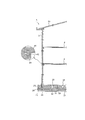
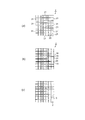
- the longitudinal cross-sectional view and partial enlarged view of the house shown in FIG. It is a top view of a foundation, (a) is a figure showing the state where the foundation block was juxtaposed, (b) is a figure showing the state where the foundation block was tensioned with PC steel materials, (c) is a groove in the foundation It is a figure which shows the state which inserted the wall. The elements on larger scale which show the corner of the foundation of Drawing 3 (b).
- the longitudinal cross-sectional view which shows a connection part between a wall and a roof.
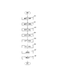
- the flowchart which shows the construction procedure of the house shown in FIG.
- the housing structure according to the present invention is a housing structure constructed of concrete blocks in order to achieve the purpose of building a disaster-resistant house in a short period of time.
- the foundation block is tensioned with a wire rod
- the wall is formed by tensioning a plurality of wall blocks fitted in the groove with the wire rod
- the plurality of roof blocks attached to the wall are fastened with a PC steel rod. This is realized by having a roof made up of
- FIG. 1 is a side view showing the house 1
- FIG. 2 is a longitudinal sectional view of the house 1 and a partially enlarged view of a connecting portion between the wall 3 and the floor 4.
- FIG. 3 is a plan view of the foundation 2.
- FIG. 4 is an enlarged view of a main part showing a corner portion of the foundation 2.
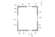
- FIG. 5 is a lateral end view showing a state in which the wall 3 is tensioned.
- FIG. 6 is a side view showing the heat exchange pipe 35 embedded in the wall 3.
- FIG. 7 is a plan view showing the floor 4.
- FIG. 8 is a longitudinal sectional view showing a portion where the wall 3 and the roof 5 are connected.
- House 1 is built on ground G lower than the surroundings.
- the house 1 includes a foundation 2 laid on the ground G, a wall 3 erected on the foundation 2, a floor 4 laid between the walls 3, a roof 5 disposed above the wall 3, It has.
- the foundation 2 is integrally connected by tensioning nine concrete blocks 21 made of concrete laid on the ground G with seven PC steel wires 22 in the longitudinal direction and the lateral direction, respectively.
- the wire rod which tensions the foundation block 21 may be a strand of PC steel in addition to the PC steel wire.
- the base block 21 is formed in a square shape in plan view with a thickness of 500 mm and a side of 2.5 m.
- Convex portions 23 and concave portions 24 are formed on the side surfaces of the base block 21, and adjacent base blocks 21 are connected with the convex portions 23 and the concave portions 24 engaged.
- Grooves 25 are formed in the surface of the base block 21 in the vertical direction and the horizontal direction. The width of the groove 25 is set to 200 mm.
- symbol 26 in FIG.3, 4 is a fixing tool holding the tension
- the wall 3 is integrally connected by tensioning the wall block 31 with six PC steel wires 32 in the vertical and horizontal directions.
- the wire rod that tensions the wall block 31 may be a PC steel wire in addition to the PC steel wire.
- Each basic block 31 is formed in an arbitrary shape according to the layout of the house 1 or the like.
- the foundation block 31 is disposed in the groove 25 corresponding to the desired installation position, and the non-shrink mortar 33 is filled in the gap between the foundation block 21 and the groove 25.
- the wall block 31 is formed with a thickness of 80 mm.
- On the inner side surface of the wall block 31, a support convex portion 34 that supports the floor 4 is provided.
- a heat exchange pipe 35 is embedded in the wall 3.
- the heat exchange pipe 35 passes a heat medium (cold water, hot air) through a zigzag path.
- the heat exchange pipe 35 is connected to a cold water supply source and a hot air supply source (not shown).
- the heat exchange pipe 35 is cooled by water cooling in the summer and heated by the hot air in the winter, thereby cooling and heating the interior of the house 1 at a low cost. it can.
- symbol 36 in FIG. 5 is a watertight door
- symbol 37 is a watertight sash.
- the floor 4 is configured by arranging a plurality of floor blocks 41 supported at both ends by the support convex portions 34 of the wall 3.
- the floor block 41 has a length of 5 m and a width of 2 m.
- the floor block 41 is connected to the support convex portion 34 via a chuck pin 42 formed in a drum shape.
- the roof 5 is tightly connected by a PC steel bar 52 to the eaves portion of the half-sized large roof block 51.
- FIG. 9 is a flowchart showing the construction procedure of the house 1.
- the foundation block 21 is placed on the ground G (S1), the PC steel wire 22 in the foundation block 21 is tensioned with a jack (not shown), and held by the fixing tool 26, whereby the foundation blocks 21 are connected to each other with the PC steel wire 22.
- the wall block 31 is fitted into the groove 25 (S3), and the PC steel wire 32 in the wall block 31 is tensioned with a jack (not shown) to construct the wall 3 (S4).
- the non-shrinkable mortar 33 is filled in the gap between the wall 3 and the groove 25 so that the foundation 2 and the wall 3 are integrated.
- the floor block 41 is dropped between the walls 3 and placed at a predetermined position (S5), and the floor block 41 and the wall 3 are connected by the chuck pins 42 (S6).
- the roof block 51 is placed on the top of the wall 3 (S7), and the eaves portion of the roof block 51 is fastened with the PC steel rod 52 (S8).
- the building structure of the house 1 is constructed according to the above procedure. After that, interior work in the house 1 is performed. Specifically, a rib-shaped heat insulating material unit is installed on the inner side surface of the wall 3 to improve the heat insulating property in the room. In addition, a floor type unit is arranged on the floor 4. Furthermore, the interior of the house 1 can be freely laid out by installing a partition in which the mortar is sprayed on the front and back of the heat insulating material anchored to the upper and lower floors 4 in the house 1.
- the present invention it is possible to build a disaster-resistant house in a short period of time by constructing the house 1 with a PC housing.
- the wall 3 is positioned by being fitted in the groove 25 of the foundation 2, the work time required for building the frame can be further shortened.
Landscapes
- Engineering & Computer Science (AREA)
- Architecture (AREA)
- Civil Engineering (AREA)
- Structural Engineering (AREA)
- Physics & Mathematics (AREA)
- Electromagnetism (AREA)
- Load-Bearing And Curtain Walls (AREA)
Abstract
La présente invention vise à fournir une structure de cadre pour une maison, avec laquelle il est possible de construire rapidement une maison qui résiste aux catastrophes. À cet effet, l'invention concerne une maison (1) qui comprend les éléments suivants : une fondation (2) obtenue par application d'une tension, à l'aide d'un fil d'acier PC (22), à une pluralité de blocs de fondation (21) qui ont des rainures (25) formées dans la surface de ces derniers ; et des parois (3) obtenues par application d'une tension, à l'aide du fil d'acier PC (22), à une pluralité de blocs de paroi (31) qui sont montés dans les rainures (25).
Priority Applications (1)
| Application Number | Priority Date | Filing Date | Title |
|---|---|---|---|
| PCT/JP2016/064334 WO2017195360A1 (fr) | 2016-05-13 | 2016-05-13 | Structure de cadre de maison |
Applications Claiming Priority (1)
| Application Number | Priority Date | Filing Date | Title |
|---|---|---|---|
| PCT/JP2016/064334 WO2017195360A1 (fr) | 2016-05-13 | 2016-05-13 | Structure de cadre de maison |
Publications (1)
| Publication Number | Publication Date |
|---|---|
| WO2017195360A1 true WO2017195360A1 (fr) | 2017-11-16 |
Family
ID=60267142
Family Applications (1)
| Application Number | Title | Priority Date | Filing Date |
|---|---|---|---|
| PCT/JP2016/064334 Ceased WO2017195360A1 (fr) | 2016-05-13 | 2016-05-13 | Structure de cadre de maison |
Country Status (1)
| Country | Link |
|---|---|
| WO (1) | WO2017195360A1 (fr) |
Citations (9)
| Publication number | Priority date | Publication date | Assignee | Title |
|---|---|---|---|---|
| US2883764A (en) * | 1955-12-12 | 1959-04-28 | Douglas W Stephens | Means for designing and laying out plans for buildings |
| US4358035A (en) * | 1979-07-02 | 1982-11-09 | Hanns Heidecker | Systems for holding small articles in a load compartment |
| JPS6199061A (ja) * | 1984-10-20 | 1986-05-17 | Taisei Corp | 建築物の温水蓄熱槽 |
| JPS61266748A (ja) * | 1985-05-17 | 1986-11-26 | 中岡 栄三 | 多階建築物の躯体構築工法 |
| JPS6216643U (fr) * | 1985-07-15 | 1987-01-31 | ||
| JP2000248614A (ja) * | 1999-03-02 | 2000-09-12 | Ando Corp | 壁式プレキャストコンクリート造建物の接合部構造 |
| WO2005010292A1 (fr) * | 2003-07-24 | 2005-02-03 | Tama Home Co., Ltd. | Parpaing, panneau de construction elabore au moyen de ce parpaing et procede pour mouler un panneau de construction |
| JP2006328805A (ja) * | 2005-05-26 | 2006-12-07 | Jsd:Kk | プレキャストコンクリート体を用いる外断熱プレストレスト建物の構築方法 |
| JP2011064001A (ja) * | 2009-09-17 | 2011-03-31 | Motoo Shoten:Kk | 建築用中空板材とその製造方法 |
-
2016
- 2016-05-13 WO PCT/JP2016/064334 patent/WO2017195360A1/fr not_active Ceased
Patent Citations (9)
| Publication number | Priority date | Publication date | Assignee | Title |
|---|---|---|---|---|
| US2883764A (en) * | 1955-12-12 | 1959-04-28 | Douglas W Stephens | Means for designing and laying out plans for buildings |
| US4358035A (en) * | 1979-07-02 | 1982-11-09 | Hanns Heidecker | Systems for holding small articles in a load compartment |
| JPS6199061A (ja) * | 1984-10-20 | 1986-05-17 | Taisei Corp | 建築物の温水蓄熱槽 |
| JPS61266748A (ja) * | 1985-05-17 | 1986-11-26 | 中岡 栄三 | 多階建築物の躯体構築工法 |
| JPS6216643U (fr) * | 1985-07-15 | 1987-01-31 | ||
| JP2000248614A (ja) * | 1999-03-02 | 2000-09-12 | Ando Corp | 壁式プレキャストコンクリート造建物の接合部構造 |
| WO2005010292A1 (fr) * | 2003-07-24 | 2005-02-03 | Tama Home Co., Ltd. | Parpaing, panneau de construction elabore au moyen de ce parpaing et procede pour mouler un panneau de construction |
| JP2006328805A (ja) * | 2005-05-26 | 2006-12-07 | Jsd:Kk | プレキャストコンクリート体を用いる外断熱プレストレスト建物の構築方法 |
| JP2011064001A (ja) * | 2009-09-17 | 2011-03-31 | Motoo Shoten:Kk | 建築用中空板材とその製造方法 |
Similar Documents
| Publication | Publication Date | Title |
|---|---|---|
| US9523201B2 (en) | Construction components having embedded internal support structures to provide enhanced structural reinforcement for, and improved ease in construction of, walls comprising same | |
| KR101182536B1 (ko) | 용도와 기능에 맞는 표면재와 구조용 철근을 적용하고 조립식 구조를 갖는 더블월 피씨패널 | |
| US20090113820A1 (en) | Prefabricated wall panel system | |
| US20120031031A1 (en) | Modular building block building system | |
| KR101776129B1 (ko) | 슬래브 및 벽체 겸용 조립형 프리캐스트 이중 구조물 및 이를 이용한 이중 구조 pc 벽체의 시공 방법 | |
| JP5574328B2 (ja) | 戸境耐震壁およびその構築方法 | |
| JP2009035998A (ja) | 外断熱・隣地空き無しrc建築工法 | |
| KR101460559B1 (ko) | 텐던체어 기능의 연결 전단보강 철물을 이용한 프리캐스트 기둥과 현장타설 슬래브의 접합부 구조 및 접합부 시공방법 | |
| KR101670553B1 (ko) | Pc벽체가 기존 건축물 외면에 접합되는 내진보강구조 | |
| KR20200075599A (ko) | 피씨 더블월을 이용한 건축물의 복수층 시공방법 | |
| EA013175B1 (ru) | Наружная стена многоэтажного каркасного здания системы аркос и способ ее возведения | |
| CN204401844U (zh) | 易于安装的叠合楼板 | |
| RU2519314C1 (ru) | Несъемная опалубка | |
| KR101326008B1 (ko) | 주택시공용 콘크리트 구조체 | |
| CN114737694A (zh) | 一种复合整体保温装配大墙板及其制作方法 | |
| KR101043454B1 (ko) | 건축 지하구조물의 마감 조립체 | |
| TR201808337T4 (tr) | Duvar elemanı, bir duvar elemanının üretilmesine yönelik yöntem ve bir duvar elemanına yönelik bir ankraj elemanı. | |
| KR101870087B1 (ko) | 피씨 트러스 벽체 구조물 및 이를 이용한 지하 구조물 시공방법 | |
| KR100521647B1 (ko) | 거푸집 겸용 건축용 패널 어셈블리 및 이를 이용한 벽체구조물 | |
| KR102507299B1 (ko) | 프리캐스트 프리스트레스 콘크리트 벽 패널을 이용한 지상 pc 주차장 및 그 시공방법 | |
| KR101086058B1 (ko) | 건축용 바닥 유닛 및 이를 이용한 바닥시공방법 | |
| JP6634259B2 (ja) | 柱梁架構 | |
| KR100255380B1 (ko) | 콘크리트 옹벽의 치장벽돌 조적구조 | |
| ES2942925A1 (es) | Módulo, sistema y método de fabricación y montaje de un forjado modular integrado postensado de hormigón de ultra alto rendimiento reforzado con fibra (UHPFRC) | |
| KR101241302B1 (ko) | 경량 기포콘크리트 블록을 사용한 벽체의 동절기 시공방법 |
Legal Events
| Date | Code | Title | Description |
|---|---|---|---|
| NENP | Non-entry into the national phase |
Ref country code: DE |
|
| 121 | Ep: the epo has been informed by wipo that ep was designated in this application |
Ref document number: 16901708 Country of ref document: EP Kind code of ref document: A1 |
|
| 122 | Ep: pct application non-entry in european phase |
Ref document number: 16901708 Country of ref document: EP Kind code of ref document: A1 |
|
| NENP | Non-entry into the national phase |
Ref country code: JP |