WO2017195467A1 - Lève-vitre - Google Patents
Lève-vitre Download PDFInfo
- Publication number
- WO2017195467A1 WO2017195467A1 PCT/JP2017/011219 JP2017011219W WO2017195467A1 WO 2017195467 A1 WO2017195467 A1 WO 2017195467A1 JP 2017011219 W JP2017011219 W JP 2017011219W WO 2017195467 A1 WO2017195467 A1 WO 2017195467A1
- Authority
- WO
- WIPO (PCT)
- Prior art keywords
- grease
- guide rail
- vehicle
- sliding surface
- sliding
- Prior art date
- Legal status (The legal status is an assumption and is not a legal conclusion. Google has not performed a legal analysis and makes no representation as to the accuracy of the status listed.)
- Ceased
Links
Images


Classifications
-
- E—FIXED CONSTRUCTIONS
- E05—LOCKS; KEYS; WINDOW OR DOOR FITTINGS; SAFES
- E05F—DEVICES FOR MOVING WINGS INTO OPEN OR CLOSED POSITION; CHECKS FOR WINGS; WING FITTINGS NOT OTHERWISE PROVIDED FOR, CONCERNED WITH THE FUNCTIONING OF THE WING
- E05F11/00—Man-operated mechanisms for operating wings, including those which also operate the fastening
- E05F11/38—Man-operated mechanisms for operating wings, including those which also operate the fastening for sliding windows, e.g. vehicle windows, to be opened or closed by vertical movement
- E05F11/382—Man-operated mechanisms for operating wings, including those which also operate the fastening for sliding windows, e.g. vehicle windows, to be opened or closed by vertical movement for vehicle windows
-
- E—FIXED CONSTRUCTIONS
- E05—LOCKS; KEYS; WINDOW OR DOOR FITTINGS; SAFES
- E05F—DEVICES FOR MOVING WINGS INTO OPEN OR CLOSED POSITION; CHECKS FOR WINGS; WING FITTINGS NOT OTHERWISE PROVIDED FOR, CONCERNED WITH THE FUNCTIONING OF THE WING
- E05F11/00—Man-operated mechanisms for operating wings, including those which also operate the fastening
- E05F11/38—Man-operated mechanisms for operating wings, including those which also operate the fastening for sliding windows, e.g. vehicle windows, to be opened or closed by vertical movement
- E05F11/48—Man-operated mechanisms for operating wings, including those which also operate the fastening for sliding windows, e.g. vehicle windows, to be opened or closed by vertical movement operated by cords or chains or other flexible elongated pulling elements, e.g. tapes
- E05F11/481—Man-operated mechanisms for operating wings, including those which also operate the fastening for sliding windows, e.g. vehicle windows, to be opened or closed by vertical movement operated by cords or chains or other flexible elongated pulling elements, e.g. tapes for vehicle windows
- E05F11/483—Man-operated mechanisms for operating wings, including those which also operate the fastening for sliding windows, e.g. vehicle windows, to be opened or closed by vertical movement operated by cords or chains or other flexible elongated pulling elements, e.g. tapes for vehicle windows by cables
- E05F11/488—Man-operated mechanisms for operating wings, including those which also operate the fastening for sliding windows, e.g. vehicle windows, to be opened or closed by vertical movement operated by cords or chains or other flexible elongated pulling elements, e.g. tapes for vehicle windows by cables with two cable connections to the window glass
-
- E—FIXED CONSTRUCTIONS
- E05—LOCKS; KEYS; WINDOW OR DOOR FITTINGS; SAFES
- E05F—DEVICES FOR MOVING WINGS INTO OPEN OR CLOSED POSITION; CHECKS FOR WINGS; WING FITTINGS NOT OTHERWISE PROVIDED FOR, CONCERNED WITH THE FUNCTIONING OF THE WING
- E05F15/00—Power-operated mechanisms for wings
- E05F15/60—Power-operated mechanisms for wings using electrical actuators
- E05F15/603—Power-operated mechanisms for wings using electrical actuators using rotary electromotors
- E05F15/665—Power-operated mechanisms for wings using electrical actuators using rotary electromotors for vertically-sliding wings
- E05F15/689—Power-operated mechanisms for wings using electrical actuators using rotary electromotors for vertically-sliding wings specially adapted for vehicle windows
-
- E—FIXED CONSTRUCTIONS
- E05—LOCKS; KEYS; WINDOW OR DOOR FITTINGS; SAFES
- E05Y—INDEXING SCHEME ASSOCIATED WITH SUBCLASSES E05D AND E05F, RELATING TO CONSTRUCTION ELEMENTS, ELECTRIC CONTROL, POWER SUPPLY, POWER SIGNAL OR TRANSMISSION, USER INTERFACES, MOUNTING OR COUPLING, DETAILS, ACCESSORIES, AUXILIARY OPERATIONS NOT OTHERWISE PROVIDED FOR, APPLICATION THEREOF
- E05Y2201/00—Constructional elements; Accessories therefor
- E05Y2201/60—Suspension or transmission members; Accessories therefor
- E05Y2201/606—Accessories therefor
- E05Y2201/61—Cooperation between suspension or transmission members
- E05Y2201/612—Cooperation between suspension or transmission members between carriers and rails
-
- E—FIXED CONSTRUCTIONS
- E05—LOCKS; KEYS; WINDOW OR DOOR FITTINGS; SAFES
- E05Y—INDEXING SCHEME ASSOCIATED WITH SUBCLASSES E05D AND E05F, RELATING TO CONSTRUCTION ELEMENTS, ELECTRIC CONTROL, POWER SUPPLY, POWER SIGNAL OR TRANSMISSION, USER INTERFACES, MOUNTING OR COUPLING, DETAILS, ACCESSORIES, AUXILIARY OPERATIONS NOT OTHERWISE PROVIDED FOR, APPLICATION THEREOF
- E05Y2201/00—Constructional elements; Accessories therefor
- E05Y2201/60—Suspension or transmission members; Accessories therefor
- E05Y2201/622—Suspension or transmission members elements
- E05Y2201/658—Members cooperating with flexible elongated pulling elements
-
- E—FIXED CONSTRUCTIONS
- E05—LOCKS; KEYS; WINDOW OR DOOR FITTINGS; SAFES
- E05Y—INDEXING SCHEME ASSOCIATED WITH SUBCLASSES E05D AND E05F, RELATING TO CONSTRUCTION ELEMENTS, ELECTRIC CONTROL, POWER SUPPLY, POWER SIGNAL OR TRANSMISSION, USER INTERFACES, MOUNTING OR COUPLING, DETAILS, ACCESSORIES, AUXILIARY OPERATIONS NOT OTHERWISE PROVIDED FOR, APPLICATION THEREOF
- E05Y2201/00—Constructional elements; Accessories therefor
- E05Y2201/60—Suspension or transmission members; Accessories therefor
- E05Y2201/622—Suspension or transmission members elements
- E05Y2201/684—Rails; Tracks
-
- E—FIXED CONSTRUCTIONS
- E05—LOCKS; KEYS; WINDOW OR DOOR FITTINGS; SAFES
- E05Y—INDEXING SCHEME ASSOCIATED WITH SUBCLASSES E05D AND E05F, RELATING TO CONSTRUCTION ELEMENTS, ELECTRIC CONTROL, POWER SUPPLY, POWER SIGNAL OR TRANSMISSION, USER INTERFACES, MOUNTING OR COUPLING, DETAILS, ACCESSORIES, AUXILIARY OPERATIONS NOT OTHERWISE PROVIDED FOR, APPLICATION THEREOF
- E05Y2800/00—Details, accessories and auxiliary operations not otherwise provided for
- E05Y2800/40—Physical or chemical protection
- E05Y2800/412—Physical or chemical protection against friction
-
- E—FIXED CONSTRUCTIONS
- E05—LOCKS; KEYS; WINDOW OR DOOR FITTINGS; SAFES
- E05Y—INDEXING SCHEME ASSOCIATED WITH SUBCLASSES E05D AND E05F, RELATING TO CONSTRUCTION ELEMENTS, ELECTRIC CONTROL, POWER SUPPLY, POWER SIGNAL OR TRANSMISSION, USER INTERFACES, MOUNTING OR COUPLING, DETAILS, ACCESSORIES, AUXILIARY OPERATIONS NOT OTHERWISE PROVIDED FOR, APPLICATION THEREOF
- E05Y2900/00—Application of doors, windows, wings or fittings thereof
- E05Y2900/50—Application of doors, windows, wings or fittings thereof for vehicles
- E05Y2900/53—Type of wing
- E05Y2900/55—Windows
Definitions
- This invention relates to the window regulator which raises / lowers the window glass of a vehicle.
- a slider base (glass carrier) to which a window glass is fixed is supported so as to be movable in the longitudinal direction of the guide rail, and the slider base is pulled by a wire and slid with respect to the guide rail.
- Those that cause the glass to move up and down are widely used.
- grease is applied to the sliding contact portion between the guide rail and the slider base in order to smoothly slide the slider base relative to the guide rail.
- Patent Document 1 a closed space that can accommodate grease and a through hole that communicates the closed space with the outside are provided in the slider base, and the slider base is slid in a state in which grease is injected into the closed space from the through hole.
- a window regulator has been proposed in which grease is applied to the sliding surface of the guide rail. According to this structure, the effort which apply
- the window regulator of Patent Document 1 has a U-shaped cross-sectional shape with the guide rail opening toward the slider base, and the slider base has a plate-like portion facing the open side of the guide rail, A pair of shoes projecting from the plate-like portion and slidably inserted into the guide rail are provided. A space surrounded by the plate-like portion of the slider base, the pair of shoes, and the inner surface of the guide rail is the closed space, and the through-hole is formed in the plate-like portion of the slider base. Since all the sliding surfaces of the guide rail (the surface on which the slider base shoe slides) face the inside of the U-shaped cross section of the guide rail, simply apply grease into the closed space through the through hole in the slider base. By simply injecting, grease can be applied to all sliding surfaces of the guide rail.
- the slider base as in Patent Document 1 is used. Even if the through hole is formed, simply injecting grease from the through hole causes a problem that grease is not applied to the sliding surface of the guide rail opposite to the side facing the through hole (back side). Therefore, in addition to the grease injection from the through hole, a step of applying the grease to the sliding surface on the back side of the guide rail is required, resulting in an increase in work man-hours and a complicated device for applying the grease.
- the present invention has been made in view of the above problems, and an object of the present invention is to provide a window regulator that can easily and reliably supply grease to the sliding portion between the sliding contact surface of the front and back surfaces of the guide rail and the slider base. To do.
- the present invention includes a guide rail that is fixed to a vehicle door panel, and a slider base that supports the window glass and is slidably supported in the longitudinal direction of the guide rail.
- the slider base In a window regulator having a first sliding surface and a second sliding surface facing one and the other in the vehicle interior / exterior direction, the slider base is provided with a grease injection portion, and the grease injection portion And an injection space in which the first sliding surface of the guide rail is located inside and a grease receiving portion that is positioned opposite to the second sliding surface of the guide rail and receives the grease injected into the injection space It is characterized by having. With this configuration of the grease injecting portion, it is possible to easily and reliably supply the grease to both the first sliding surface and the second sliding surface of the guide rail.
- the grease receiving part is preferably an elastically deformable protrusion that protrudes from the inner surface of the injection space.
- the grease receiving portion has an inclined shape that proceeds in a direction away from the second sliding surface in the vehicle interior / exterior direction as it proceeds from the proximal end portion connected to the inner surface of the injection space toward the distal end side.
- the guide rail has an edge facing in the vehicle front-rear direction between the first sliding surface and the second sliding surface, and the edge is located inside the injection space, so that the first sliding surface It becomes easy to distribute the grease in the space on the side and the space on the second sliding surface side.
- the slider base includes a pair of guide portions that are slidable with respect to the first sliding surface and the second sliding surface at different positions in the longitudinal direction of the guide rail. It is preferable that the grease injection part is located between the pair of guide parts. With this configuration, the grease injected into the grease injection portion can be efficiently applied to the guide rail by each guide portion. Further, it is difficult for excess grease to remain outside the sliding range of the slider base in the guide rail.
- an anti-sway portion that is slidable with respect to the first sliding surface may be provided. Further, if a pair of steady rests are provided in the injection space in different positions in the longitudinal direction of the guide rail, and the grease receiving part is positioned between the pair of steady rests, the second sliding It becomes easy to guide grease to the surface side.
- the grease injecting portion configured to be able to guide the grease to both the first sliding surface and the second sliding surface of the guide rail by injecting the grease into the injecting opening is provided with the slider base. Therefore, simple and reliable supply of grease to the guide rail and the sliding portion of the slider base in the window regulator can be realized.
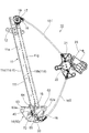
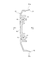
- the window regulator 10 shown in FIG.1 and FIG.2 has the guide rail 11 which is a elongate member, and illustration is abbreviate
- the guide rail 11 is arranged in a state in which the guide rail 11 is attached to the door panel of the vehicle so that the longitudinal direction thereof is substantially in the vertical direction (height direction) of the vehicle.
- the door panel to which the window regulator 10 is attached is a side door of the vehicle, and in the completed state of the vehicle, the left-right direction in FIGS. 1 and 2 is the vehicle front-rear direction.
- the window regulator 10 has a slider base (glass carrier) 14 that is supported so as to be movable up and down along the guide rail 11 in the vertical direction of the vehicle and supports a window glass (not shown).
- a slider base glass carrier
- One end of each of the pair of drive wires 15 and 16 is connected to the slider base 14.
- a pulley bracket 17 is fixed in the vicinity of the upper end of the guide rail 11 in the longitudinal direction, and a guide pulley 18 is rotatably supported on the pulley bracket 17 via a pulley support shaft 19.
- the drive wire 15 extends upward from the slider base 14 along the guide rail 11 and is supported by a wire guide groove formed on the outer peripheral surface of the guide pulley 18. As the drive wire 15 advances and retreats, the guide pulley 18 rotates about the pulley support shaft 19.
- a wire guide member 20 is provided near the lower end of the guide rail 11 in the longitudinal direction.
- the drive wire 16 extends downward from the slider base 14 along the guide rail 11 and is guided by the wire guide member 20.
- the wire guide member 20 is fixed to the guide rail 11, and the drive wire 16 is supported so as to be able to advance and retract along a wire guide groove formed in the wire guide member 20.
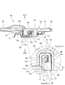
- the drive wire 15 coming out of the guide pulley 18 is inserted into a tubular outer tube 15T and wound around a drive drum 22 provided in a drum housing 21 to which the outer tube 15T is connected.
- the drive wire 16 coming out of the wire guide member 20 is inserted into a tubular outer tube 16T and wound around a drive drum 22 provided in a drum housing 21 to which the outer tube 16T is connected.
- a spiral groove around which the drive wire 15 and the drive wire 16 are wound is formed on the outer peripheral surface of the drive drum 22.
- the drive drum 22 is rotated by a motor 23.
- the drum housing 20 is fixed to a door panel (inner panel).
- the driving drum 21 rotates forward and backward by the driving force of the motor 22, one of the driving wire 15 and the driving wire 16 increases the winding amount of the driving drum 22 into the spiral groove, and the other from the spiral groove of the winding drum.
- the slider base 14 is moved along the guide rail 11 by the relationship of pulling and relaxation of the driving wire 15 and the driving wire 16. As the slider base 14 moves, the window glass moves up and down.
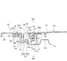
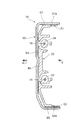
- the guide rail 11 protrudes toward the vehicle outer side on one side of a plate-like portion 11a having surfaces facing the vehicle inner side and the vehicle outer side (vehicle width direction).
- the support flange 11c protrudes laterally from the side wall 11b. Sliding surfaces 11d and 11e are formed on the front and back of the side wall 11b and the support flange 11c.
- the sliding surface 11d in the support flange 11c is a first sliding surface 11d-1
- the sliding surface 11e in the support flange 11c is a second sliding surface 11e-1 (see FIGS. 4 and 6).
- the first sliding surface 11d-1 is a surface facing the vehicle outer side
- the sliding surface 11e is a surface facing the vehicle inner side.
- the support flange 11c further has an edge surface 11f formed between the first sliding surface 11d-1 and the second sliding surface 11e-1.
- the edge surface 11f is located at one edge in the vehicle front-rear direction, and the edge surface 11f faces the front or rear of the vehicle with the guide rail 11 attached to the door panel.
- the guide rail 11 further has a U-shaped projecting portion 11g projecting toward the vehicle outer side with respect to the plate-like portion 11a on the side opposite to the side on which the side wall 11b and the support flange 11c are provided. have.
- the slider base 14 is configured by combining a sliding member 30 made of synthetic resin and a holder member 60 made of metal.
- FIG. 5 shows the sliding member 30 as a single unit.
- the sliding member 30 has a guide shoe 31 (guide portion) at the upper end in the vehicle vertical direction of the slider base 14 and a guide shoe 32 (guide portion) at the lower end.
- the guide shoe 31 includes a side wall 80 and a side wall 81 that are separated in the vehicle front-rear direction, a bottom wall 82 that connects the side wall 80 and the side wall 81, and a part of the side wall 81 on the side wall 80 side.
- a narrow groove portion 84 is formed between the side wall 80 and the convex portion 83, and the wide groove portion wider than the narrow groove portion 84 is formed between the side wall 80 and the side wall 81. 85 is formed.
- a narrowed portion 86 for partially narrowing the width of the guide shoe 31 is formed on both sides of the side wall 80 and the side wall 81.
- the narrowed portion 86 is formed in a partial region near the bottom wall 82 of the side wall 80 and the side wall 81.
- the guide shoe 31 can be elastically deformed, and in particular, is easily elastically deformed in the vehicle front-rear direction in which the distance between the side wall 80 and the side wall 81 (projection 83) is changed.
- FIG. 11 shows the guide shoe 31 in a free state.
- the guide shoe 31 in the free state has a shape in which the distance between the side wall 80 and the side wall 81 increases as the distance from the bottom wall 82 increases.
- the detailed structure of the guide shoe 32 is omitted, but it has the same configuration as the guide shoe 31 and can be elastically deformed. Parts common to the guide shoe 31 in the guide shoe 32 are denoted by the same reference numerals as the guide shoe 31.
- the sliding member 30 has a pair of wire guide grooves 33 and 34 positioned between the guide shoe 31 and the guide shoe 32 in the vehicle vertical direction.
- the wire guide grooves 33 and 34 have wire introduction ports 33 a and 34 a that open on one side of the sliding member 30, respectively, and wire end storage portions 35 and 36 are formed on the other side of the sliding member 30.
- the wire guide groove 33 is a groove portion that communicates the wire introduction port 33 a and the wire end storage portion 35.
- the wire introduction port 33 a is located above the wire end storage portion 35, and the wire guide groove 33 extends obliquely downward from the wire introduction port 33 a toward the wire end storage portion 35.
- the wire guide groove 34 is a groove portion that communicates the wire introduction port 34 a and the wire end storage portion 36.
- the wire introduction port 34 a is located below the wire end storage portion 36, and the wire guide groove 34 extends obliquely upward from the wire introduction port 34 a toward the wire end storage portion 36.
- the wire guide groove 33 and the wire guide groove 34 intersect at a crossing portion 37 in the vicinity of the wire introduction port 33a and the wire introduction port 34a.
- the wire end storage portions 35 and 36 are concave portions wider than the groove widths of the wire guide grooves 33 and 34, respectively.
- the wire end storage portion 35 is positioned on the extension of the wire guide groove 33 and protrudes obliquely downward from the side portion of the sliding member 30, and the wire end storage portion 36 is positioned on the extension of the wire guide groove 34 and slides. It protrudes obliquely upward from the side of the moving member 30.
- an insertion groove 38 that intersects the wire guide groove 33 and an insertion groove 39 that intersects the wire guide groove 34 are formed on the sliding member 30, an insertion groove 38 that intersects the wire guide groove 33 and an insertion groove 39 that intersects the wire guide groove 34 are formed.
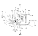
- the sliding member 30 has a grease injection portion 40 in a fan-shaped region surrounded by the wire guide grooves 33 and 34 and the insertion grooves 38 and 39 and having an intersection portion 37 as a vertex. Is formed.
- the grease injection part 40 has an injection space 55 penetrating the sliding member 30 in the vehicle interior / exterior direction, and the injection space 55 has an opening 56 on the vehicle exterior side and an opening 57 on the vehicle interior side.
- a pair of steady-state projections 41 (stabilization portions) and a grease-receiving projection 42 (grease-receiving portions) are provided in the injection space 55.
- the pair of steady rest protrusions 41 are provided at different positions in the vehicle vertical direction.
- the steady-state protrusion 41 is a cantilever-like protrusion whose base end portion is connected to a position near the opening 56 on the vehicle outside of the inner surface of the injection space 55, and is separated from the base end portion. It has an inclined shape toward the inside of the vehicle as it advances toward the tip side.
- the steady rest protrusion 41 can be elastically deformed in the vehicle interior / exterior direction with the base end as a fulcrum.
- the grease receiving protrusion 42 is located between the pair of steady rest protrusions 41 in the vehicle vertical direction.
- the grease receiving protrusion 42 is a cantilevered protrusion whose base end is connected to a position near the opening 57 on the vehicle inner side of the inner surface of the injection space 55, and is separated from the base end. It has the inclination part 42b which goes to a vehicle inner side as it advances to a front end side, and the front-end
- the steady rest protrusion 41 can be elastically deformed in the vehicle interior and exterior directions with the base end of the inclined portion 42b as a fulcrum.
- the sliding member 30 is provided with fastening seats 43 and fastening seats 44 on both sides of the vehicle in the vertical direction across the intersection 37, and the side of the insertion groove 38 and the insertion groove 39 (
- a fastening seat 45 is provided on the side opposite to the grease injection portion 40.
- the fastening seats 43, 44 and 45 are formed with insertion holes 43a, 44a and 45a penetrating in the vehicle interior / exterior direction.
- the sliding member 30 further has two fixed support portions 46 and 47 and seven elastic support portions 48, 49, 50, 51, 52, 53 and 54.
- the fixed support portion 46 is located on the side of the fastening seat 43
- the fixed support portion 47 is located on the side of the fastening seat 44, and has support surfaces 46a and 47a that face the outside of the vehicle.
- the elastic support portions 48, 49, 50, 51, 52, 53, and 54 are portions that can be elastically deformed in respective directions described later
- the fixed support portions 45 and 46 are respectively elastic support portions 48, 49, 50, 51. , 52, 53, and 54, it is a part having a fixed shape that is less likely to cause elastic deformation.
- the elastic support portion 48 is located on the side of the intersecting portion 37 and is located between the fixed support portion 45 and the fixed support portion 46 in the vehicle vertical direction.
- the elastic support portion 48 is a cantilevered protruding piece whose base end portion is connected to the vehicle outer surface of the sliding member 30, and has a contact surface 48 a facing the vehicle outer side, It can be elastically deformed in and out of the vehicle.
- FIG. 6 shows the free state of the elastic support portion 47, and the elastic support portion 48 in the free state increases the amount of protrusion to the vehicle outer side as it proceeds from the base end portion to the distal end side.
- the elastic support portion 49 is a cantilevered protruding piece that protrudes obliquely upward from the wire end storage portion 35, and has a contact surface 49 a facing the vehicle outer side.
- the elastic support portion 50 is a cantilevered protruding piece that protrudes obliquely downward from the wire end storage portion 36, and has an abutment surface 50a that faces the outside of the vehicle. Similar to the elastic support portion 48, the elastic support portions 49 and 50 can be elastically deformed in the vehicle interior and exterior directions, respectively, and the elastic support portions 49 and 50 in the free state move outward from the base end portion toward the front end side. The protruding amount is increased.
- the elastic support portion 51 is located between the guide shoe 31 and the wire end storage portion 36 in the vehicle front-rear direction
- the elastic support portion 52 is located between the guide shoe 32 and the wire end storage portion 35 in the vehicle front-rear direction.
- the elastic support portion 51 is a cantilevered protruding piece that protrudes from the upper edge of the sliding member 30 toward the inside of the vehicle, and has a contact surface 51 a that faces upward.
- the elastic support portion 52 is a cantilevered protruding piece that protrudes from the lower edge of the sliding member 30 toward the inside of the vehicle, and has a contact surface 52a that faces downward.
- the elastic support portions 51 and 52 can be elastically deformed in the vehicle vertical direction, respectively, and FIGS. 5 and 7 show the free states of the elastic support portions 51 and 52.
- the elastic support portion 51 in the free state has a curved shape in which the protruding amount of the contact surface 51a upward increases as it advances toward the front end side (inside the vehicle). ), The amount of protrusion of the downward contact surface 52a increases.
- the elastic support portions 51 and 52 gradually widen the distance in the vertical direction of the vehicle as they advance toward the front end side (the vehicle inner side).
- the elastic support portion 53 is located on the opposite side of the elastic support portion 51 (above the fastening seat 43) across the guide shoe 31 in the vehicle front-rear direction. Similar to the elastic support portion 51, the elastic support portion 53 is a cantilevered protruding piece that protrudes from the upper edge of the sliding member 30 toward the inside of the vehicle, and a contact surface 53a that faces upward (obliquely upward).
- the elastic support portion 54 is a cantilevered protruding piece that protrudes from the lower edge portion of the fixed support portion 47 toward the inside of the vehicle, and has a contact surface 54a that faces downward.
- the elastic support portions 53 and 54 can be elastically deformed in the vehicle vertical direction, respectively, and FIG.
- the elastic support portion 53 in the free state has a curved shape in which the protruding amount of the contact surface 53a upward increases as it advances toward the front end side (inside the vehicle), and the elastic support portion 54 in the free state has a front end side (inside the vehicle interior). ), The amount of protrusion of the downward contact surface 54a increases.
- the elastic support portions 53 and 54 gradually increase the distance in the vertical direction of the vehicle as they advance toward the front end side (the vehicle inner side).
- the holder member 60 includes a plate-like cover portion 61 and glass attachment portions 62 and 63 located on both sides of the cover portion 61.
- the glass attachment portion 62 and the glass attachment portion 63 are formed with bolt insertion holes 62a and 63a into which bolts (not shown) for fastening and fixing the window glass are inserted.
- a clamping part 64 is provided on the upper end side, and a clamping part 65 is provided on the lower end side.
- the sandwiching portion 64 is a U-shaped cross-section having a pair of side walls 87 and 88 that face each other in the longitudinal direction of the vehicle and a bottom wall 89 that connects the pair of side walls 87 and 88. Yes, the inside of the vehicle opposite to the bottom wall 89 is open.
- the sandwiching part 65 has the same configuration as the sandwiching part 64, and portions common to the sandwiching part 64 in the sandwiching part 65 are denoted by the same reference numerals as the sandwiching part 64.
- a flange 66 that extends to the glass attachment portion 62 continuously to the side wall 87 of the holding portion 64, and a flange portion 67 that extends to the glass attachment portion 63 continuously to the side wall 88 of the holding portion 64. Is formed.
- a flange 68 that extends to the glass mounting portion 62 continuously from the side wall 87 of the holding portion 65 and a flange 69 that extends to the glass mounting portion 63 continuously from the side wall 88 of the holding portion 65 are formed.
- Each of the flanges 66, 67, 68 and 69 has a shape in which the periphery of the cover portion 61 is bent inward of the vehicle (see FIG. 10).
- an insertion piece 70 and an insertion piece 71 which are paired with different positions in the vehicle vertical direction.
- the insertion piece 70 and the insertion piece 71 are bifurcated protrusions that are formed by cutting and raising a part of the cover portion 61 toward the vehicle interior side, and having a groove at the tip.
- a through hole 72 is formed in the cover portion 61 by cutting and raising when the insertion piece 70 and the insertion piece 71 are formed.
- fastening holes 73, 74, and 75 are formed in the cover portion 61 at positions surrounding the through hole 72.
- the fastening holes 73, 74 and 75 are arranged in a positional relationship corresponding to the insertion holes 43 a, 44 a and 45 a of the sliding member 30.
- the driving wire 15 and the driving wire 16 are assembled to the sliding member 30.
- the end of the drive wire 15 is provided with a wire end 76 having a diameter larger than that of the drive wire 15.
- the wire end 76 is inserted into the wire end storage portion 35, and the drive wire 15 is Insert into the wire guide groove 33.
- a wire end 77 having a diameter larger than that of the drive wire 16 is provided at the end of the drive wire 16, and the wire end 77 is inserted into the wire end housing portion 36 and the drive wire 16 is inserted into the wire guide groove 34. .
- the drive wire 15 inserted into the wire guide groove 33 and the drive wire 16 inserted into the wire guide groove 34 pass through the intersection 37 and pass through the wire introduction port 33a and the wire introduction port 34a, respectively. Pulled out. As shown in FIGS. 6 and 9, the driving wire 15 and the driving wire 16 are arranged at different positions in the vehicle interior and exterior directions at the intersection 37, and the driving wire 15 and the driving wire 16 do not interfere with each other.
- the fixed support portion 46 of the sliding member 30 is drawn from the wire introduction port 33 a to the outside of the sliding member 30, and from the arrangement position of the drive wire 15 heading upward (guide pulley 18 side). Also, the shape protrudes to the side of the sliding member 30.
- the fixed support portion 47 is pulled out to the outside of the sliding member 30 from the wire introduction port 34a and protrudes to the side of the sliding member 30 from the arrangement position of the drive wire 16 directed downward (to the wire guide member 20 side). It has a shape to do.
- the holder member 60 is assembled by covering the sliding member 30 with the cover 61 from the outside with the side from which the flanges 66, 67, 68 and 69 and the insertion pieces 70, 71 protrude facing inward.
- the guide shoe 31 and the guide of the sliding member 30 are placed inside the clamping portion 64 and the clamping portion 65 provided on the holder member 60.
- the shoe 32 is inserted.
- the guide shoe 31 is inserted into the holding portion 64, thereby changing from the free state shown in FIG. 11 to the elastically deformed state shown in FIG.
- the side wall 87 and the side wall 81 are elastically deformed so as to approach each other.
- a gap in the vehicle front-rear direction exists with respect to the side wall 87 and the side wall 88 of the sandwiching portion 64 at the portion where the narrowed portion 86 is formed in the guide shoe 31.
- the guide shoe 32 is inserted into the holding portion 65, and is in an elastically deformed state in which the side wall 80 and the side wall 81 are brought close to each other.
- a gap in the vehicle front-rear direction is present with respect to the side wall 87 and the side wall 88 of the sandwiching portion 65 at the portion where the narrowed portion 86 is formed in the guide shoe 32.
- the contact surfaces 48a, 49a and 50a of the elastic support portions 48, 49 and 50 of the sliding member 30 are in contact with and supported by the cover portion 61 of the holder member 60.
- the elastic support portion 48 is elastically deformed toward the vehicle inner side in a state where the contact surface 48 a is in contact with the cover portion 61.
- the elastic support portions 49 and 50 similarly contact the contact surfaces 49 a and 50 a with the cover portion 61 while being elastically deformed toward the vehicle interior side.
- the contact surfaces 51a, 52a, 53a and 54a of the elastic support portions 51, 52, 53 and 54 are respectively flanges 66, 67, 68 and 69 of the holder member 60.
- FIG. 10 the elastic support portion 51 is brought into contact with the flange 67 while being elastically deformed downward, and the elastic support portion 52 is elastically deformed upward. Then, the contact surface 52a is brought into contact with the flange 69.
- the elastic support portion 53 causes the contact surface 53 a to contact the flange 66 in a state where it is elastically deformed downward, and the elastic support portion 54.
- the contact surface 54a is brought into contact with the flange 68 while being elastically deformed upward.
- the position of the sliding member 30 in the vehicle front-rear direction with respect to the holder member 60 is determined, and the contact surfaces 48a, 49a of the elastic support portions 48, 49 and 50 and
- the position of the sliding member 30 in the vehicle interior / exterior direction with respect to the holder member 60 is determined by the contact of the cover member 61 with the cover 50a, and the contact surfaces 51a, 52a, 53a and 54a of the elastic support portions 51, 52, 53 and 54 are flanged.
- the position of the sliding member 30 in the vertical direction of the vehicle with respect to the holder member 60 is determined by contacting with 66, 67, 68 and 69. In each of these portions, the abutting portion on the sliding member 30 side abuts in an elastically deformed state, so that variations in component accuracy and assembly accuracy between the sliding member 30 and the holder member 60 can be absorbed.
- the support surfaces 46 a and 47 a of the fixed support portions 46 and 47 of the slide member 30 face the cover portion 61 of the holder member 60 and the top of the fixed support portion 46.
- the edge portion faces the flange 66
- the lower edge portion of the fixed support portion 47 faces the flange 68 (FIG. 8).
- the insertion piece 70 is inserted into the insertion groove 38 and the insertion piece 71 is inserted into the insertion groove 39.
- Each of the insertion pieces 70, 71 has a groove at the tip, and the drive wire 15 is inserted into the groove of the insertion piece 70, and the drive wire 16 is inserted into the groove of the insertion piece 71.
- the sliding member 30 and the holder member 60 are fastened by three caulking pins 78.
- the caulking pin 78 has a head portion 78a, an intermediate diameter portion 78b, and a small diameter portion 78c.
- the small diameter portion 78c is inserted into the fastening holes 73, 74 and 75 of the holder member 60
- the intermediate diameter portion 78b is inserted into the insertion holes 43a, 44a and 45a of the sliding member 30, and the head portion 78a is inserted.
- FIG. 9 shows the fastening by the caulking pin 78 at the place of the fastening seat 45 and the fastening hole 75, but also at the place of the fastening seat 43 and the fastening hole 73 and the place of the fastening seat 44 and the fastening hole 74. Similarly, the fastening by the caulking pin 78 is performed.
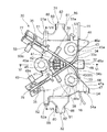
- the slider base 14 configured as described above is assembled to the guide rail 11.
- the upper and lower guide shoes 31, 32, and the pair of anti-shake projections 41 and the grease receiving projections 42 located in the middle thereof can slidably contact the guide rail 11.
- the side wall 11 b is fitted into the narrow groove portion 84, and the support flange 11 c is inserted into the wide groove portion 85.
- the wide groove 85 is sized to allow the support flange 11c to be inserted with sufficient margin in the vehicle interior / exit direction.
- the support flange 11c and the side wall 11b of the guide rail 11 are in the injection space 55 of the grease injection portion 40.
- the side wall 11b and the support flange 11c of the guide rail 11 are located substantially at the center of the injection space 55 in the vehicle longitudinal direction.
- the entire support flange 11 c is located in the injection space 55, and most of the side wall 11 b is located in the injection space 55, and a part projects from the opening 57 to the vehicle interior side.
- the first sliding surface 11d-1 of the support flange 11c faces the opening 56 side of the injection space 55
- the second sliding surface 11e-1 faces the opening 57 side of the injection space 55.
- the edge surface 11f of the guide rail 11 is opposed to the inner surface of the injection space 55 with a gap.
- the pair of steady stop protrusions 41 abut against the first sliding surface 11d-1 on the vehicle outer side of the support flange 11c in an elastically deformed state.
- the support flange 11c is positioned in the wide groove portion 85 in a state where the second sliding surface 11e-1 on the vehicle inner side is brought closer to the convex portion 83 side of the guide shoe 31 (32). Accordingly, the slider base 14 has the first sliding surface 11d-1 and the second sliding surface formed by the guide shoe 31 (32) convex portion 83 and the pair of anti-rest projections 41 arranged at different positions in the vehicle vertical direction.
- the slider base 14 can be moved in the longitudinal direction of the guide rail 11 while sliding the guide shoes 31 and 32 and the pair of anti-rest projections 41 with respect to the side wall 11b and the support flange 11c.
- the grease receiving projection 42 of the slider base 14 has an inclined portion 42a on the vehicle interior side of the second sliding surface 11e-1 of the support flange 11c.
- the distal end bent part 42b is located opposite to the sliding surface 11e of the side wall 11b.
- FIG 1 and 2 show a completed state of the window regulator 10 in which the routing of the drive wire 15 and the drive wire 16 is completed and the slider base 14 is slidably supported with respect to the guide rail 11.
- the drive drum 22 in the drum housing 21 is rotated in this completed state, one of the drive wire 15 and the drive wire 16 is pulled and the other is relaxed according to the rotation direction.
- the wire ends 76 and 77 transmit force to the corresponding end surfaces of the wire end storage portions 35 and 36 (end portions on the side connected to the wire guide grooves 33 and 34).
- the insertion piece 70 is positioned on the extension of the direction of application of the load applied from the wire end 76 to the end surface of the wire end storage portion 35 when the drive wire 15 is pulled, and the insertion piece 71 is pulled by the drive wire 16. When this is done, it is located on an extension of the direction of action of the load applied from the wire end 77 to the end face of the wire end storage portion 36.
- the load in the pulling direction applied by the drive wires 15 and 16 is received by the insertion pieces 70 and 71 that are part of the metal holder member 60, thereby contributing to an improvement in the load bearing performance of the slider base 14.
- the loosened drive wires 15 and 16 are pressed in a direction away from the end surfaces of the wire ends 70 and 72 by the force of a spring (not shown) disposed in the wire end storage portions 35 and 36 to remove the slack.
- 1 and 2 show a state in which the slider base 14 is located at the lowermost part of the movable range along the longitudinal direction of the guide rail 11.
- the injection space 55 of the grease injection portion 40 in the sliding member 30 is passed through the through hole 72 of the holder member 60. Visible from the outside of the vehicle. Then, lubricating grease is injected into the injection space 55 of the grease injection portion 40. The grease is injected into the injection space 55 from the outside of the vehicle through the through hole 72 and the opening 56.
- the side wall 11 b and the support flange 11 c of the guide rail 11 are located substantially in the center in the vehicle front-rear direction (see FIGS. 6 and 9). The injected grease is stored around the side wall 11b and the support flange 11c.
- a pair of steady-state projections 41 and a grease receiving projection 42 are provided inside the injection space 55, and the arrow lines G 1 and G 2 in FIG. 6 correspond to the steady-state projection 41 and the grease receiving projection 42 in the injection space 55.
- the flow of grease along is shown schematically.
- the steady-state projection 41 has a proximal end connected to the vicinity of the opening 56 on the vehicle exterior side of the grease injecting portion 40 and is inclined toward the distal end contacting the sliding surface 11d of the support flange 11c.
- the grease (G1) flowing along the steady-state protrusion 41 is stored in a space facing the support flange 11c and the sliding surface 11d of the side wall 11b.
- the grease injected from the opening 56 is stored on the first sliding surface 11d-1 of the support flange 11c.
- the grease receiving projection 42 has a base end connected to the inner surface of the injection space 55 positioned on the vehicle inner side than the support flange 11 c and is inclined from the base end toward the vehicle inner side.
- the support flange 11c extends to the back of the sliding surface 11e (the position inside the vehicle). Therefore, the grease (G2) flowing along the grease receiving projection 42 passes between the edge surface 11f of the guide rail 11 and the inner surface of the injection space 55 and advances to the vehicle inner side than the flange 11c, and the second of the support flange 11c. It is stored in a space facing the sliding surface 11e-1 and the sliding surface 11e of the side wall 11b (hereinafter referred to as a back side storage space).
- the grease receiving projection 42 has the inclined portion 42a, the second sliding surface 11e-1 of the support flange 11c and the inclined portion 42a as it advances toward the back side (in the direction of the side wall 11b) of the back side storage space. , And the grease easily flows into the back side storage space along the inclined portion 42a.
- the grease receiving protrusion 42 has the bent end portion 42 b close to the sliding surface 11 e of the side wall 11 b, and the grease does not easily flow out from the back side storage space to the vehicle interior side.
- the injection space 55 penetrates the sliding member 30 in the vehicle interior / exterior direction. However, as shown in FIG. 5, most of the injection space 55 and the pair of steady-state projections 41 are seen from the vehicle exterior (opening 56 side). Since the grease receiving projection 42 occupies, the grease injected from the outside of the vehicle is effectively stored in the injection space 55, and there is little risk of the grease leaking out to the inside of the vehicle. Further, since the grease receiving protrusion 42 is located between the pair of steady rest protrusions 41, the grease easily flows toward the grease receiving protrusion 42, and it is easy to efficiently supply the grease to the back side storage space.
- the first sliding of the support flange 11c facing the injection-side opening 56 by injecting grease from one direction (the vehicle outer side) into the injection space 55 of the grease injection portion 40 provided in the slider base 14.
- the region along the surface 11d-1 and the region along the sliding surface 11d of the side wall 11b continuous to the first sliding surface 11d-1 but also the back-side storage space at a position that cannot be directly seen from the outside of the vehicle ( The grease can be reliably distributed to the second sliding surface 11e-1 of the support flange 11c and the space on the sliding surface 11e side of the side wall 11b.
- the grease receiving projection 42 of the slider base 14 can be elastically deformed in the vehicle interior / exterior direction, when the grease receiving projection 42 comes into contact with the support flange 11c due to a swing of the slider base 14 in the vehicle interior / exterior direction with respect to the guide rail 11 or the like.
- the grease receiving projections 42 are appropriately elastically deformed to absorb the load and keep the slider base 14 from sliding smoothly.
- the grease receiving protrusion 42 that is elastically deformable and has excellent followability with respect to the guide rail 11 is used to apply grease to the back side storage space (the sliding surface 11e and the second sliding surface 11e-1 side) of the guide rail 11. The grease can be supplied to the sliding portion with the guide rail 11 more reliably.
- the grease injection part 40 is located between the guide shoe 31 and the guide shoe 32 in the vehicle vertical direction of the slider base 14. Therefore, when the slider base 14 reaches the moving end in the vertical direction of the vehicle, excess grease that does not contribute to improving the smoothness of sliding of the slider base 14 is unlikely to remain in the vicinity of the upper end or the lower end of the guide rail 11. The grease can be supplied to the sliding portion between the guide rail 11 and the slider base 14 without waste.
- the window glass is applied from the outside of the vehicle to the glass mounting portion 62 and the glass mounting portion 63 of the holder member 60, and a glass fastening bolt is inserted through the bolt insertion holes 62a and 63a to fix the window glass. Then, the slider base 14 is brought into a state of supporting the window glass.
- the slider base 14 is configured by combining the sliding member 30 made of synthetic resin and the holder member 60 made of metal. What is a combination of such a plurality of members? Different slider bases can be applied to the present invention.
- the window regulator 10 of the embodiment is configured to inject grease from the opening 56 on the vehicle exterior side of the injection space 55
- the present invention does not limit the grease injection direction in the vehicle interior / exterior direction.
- the window regulator according to the present invention supplies grease easily and reliably to the sliding portion of the slider base with respect to both the first sliding surface and the second sliding surface of the guide rail. This contributes to improving the productivity and operability of the window regulator.
Landscapes
- Window Of Vehicle (AREA)
- Engineering & Computer Science (AREA)
- Mechanical Engineering (AREA)
- Power-Operated Mechanisms For Wings (AREA)
Abstract
L'invention concerne un lève-vitre comprenant un rail de guidage qui est fixé à un panneau de porte de véhicule, et une base de curseur qui supporte une vitre de fenêtre et est soutenue de façon à pouvoir coulisser, dans une direction de longueur du rail de guidage, le long de surfaces de glissement avant et arrière du rail de guidage, ledit lève-vitre ayant, sur le rail de guidage, une première surface de glissement et une seconde surface de glissement, leurs sections de glissement faisant face vers l'une et l'autre des directions intérieure/extérieure de véhicule, lesdites sections de glissement se trouvant à l'endroit où un glissement se produit avec la base de curseur, une section d'injection de graisse étant située sur la base de curseur, ladite section d'injection de graisse ayant un espace d'injection qui s'ouvre dans une direction intérieure/extérieure de véhicule et a la première surface de glissement du rail de guidage positionnée à l'intérieur de ce dernier, et ayant une section de réception de graisse qui est positionnée en regard de la seconde surface de glissement du rail de guidage et reçoit la graisse injectée dans l'espace d'injection. Au moyen de cette section d'injection de graisse, la graisse peut être fournie de manière simple et fiable aux sections de glissement où un glissement se produit entre la base de curseur et les première et seconde surfaces de glissement du rail de guidage.
Priority Applications (2)
| Application Number | Priority Date | Filing Date | Title |
|---|---|---|---|
| CN201780015159.2A CN108779655B (zh) | 2016-05-12 | 2017-03-21 | 车窗调节器 |
| US16/082,450 US10753137B2 (en) | 2016-05-12 | 2017-03-21 | Window regulator |
Applications Claiming Priority (2)
| Application Number | Priority Date | Filing Date | Title |
|---|---|---|---|
| JP2016-096215 | 2016-05-12 | ||
| JP2016096215A JP6682345B2 (ja) | 2016-05-12 | 2016-05-12 | ウインドレギュレータ |
Publications (1)
| Publication Number | Publication Date |
|---|---|
| WO2017195467A1 true WO2017195467A1 (fr) | 2017-11-16 |
Family
ID=60267546
Family Applications (1)
| Application Number | Title | Priority Date | Filing Date |
|---|---|---|---|
| PCT/JP2017/011219 Ceased WO2017195467A1 (fr) | 2016-05-12 | 2017-03-21 | Lève-vitre |
Country Status (5)
| Country | Link |
|---|---|
| US (1) | US10753137B2 (fr) |
| JP (1) | JP6682345B2 (fr) |
| CN (1) | CN108779655B (fr) |
| TW (1) | TWI738742B (fr) |
| WO (1) | WO2017195467A1 (fr) |
Families Citing this family (13)
| Publication number | Priority date | Publication date | Assignee | Title |
|---|---|---|---|---|
| JP6846116B2 (ja) * | 2016-04-12 | 2021-03-24 | シロキ工業株式会社 | 車両用開閉体駆動装置 |
| JP6985892B2 (ja) * | 2017-11-06 | 2021-12-22 | シロキ工業株式会社 | ウインドレギュレータ |
| JP6989353B2 (ja) * | 2017-11-06 | 2022-01-05 | シロキ工業株式会社 | ウインドレギュレータ |
| DE102018213172A1 (de) * | 2018-08-07 | 2020-02-13 | Brose Fahrzeugteile Gmbh & Co. Kommanditgesellschaft, Bamberg | Schienengleiter für einen Fensterheber eines Kraftfahrzeugs |
| JP7187981B2 (ja) * | 2018-10-29 | 2022-12-13 | 株式会社アイシン | ウインドレギュレータ及びその組付方法 |
| JP7187980B2 (ja) * | 2018-10-29 | 2022-12-13 | 株式会社アイシン | ウインドレギュレータ及びその組付方法 |
| JP7238338B2 (ja) * | 2018-10-29 | 2023-03-14 | 株式会社アイシン | ウインドレギュレータ及びその組付方法 |
| US11499361B2 (en) * | 2019-02-05 | 2022-11-15 | Magna Closures Inc. | Lightweight lifter plate assembly for vehicle window |
| JP6954956B2 (ja) * | 2019-06-27 | 2021-10-27 | 株式会社ハイレックスコーポレーション | 対象物移動装置 |
| CN111372414B (zh) * | 2020-02-25 | 2022-05-24 | 北京全路通信信号研究设计院集团有限公司 | 一种铁路信号系统通用电源接口层模块 |
| JP7351237B2 (ja) * | 2020-02-26 | 2023-09-27 | 株式会社アイシン | ウインドレギュレータ |
| JP7416541B2 (ja) * | 2022-03-18 | 2024-01-17 | 株式会社城南製作所 | ウインドレギュレータ及びガイドレールの取付け方法 |
| JP7789635B2 (ja) * | 2022-07-28 | 2025-12-22 | 株式会社ハイレックスコーポレーション | キャリアプレートおよびウインドレギュレータ |
Citations (3)
| Publication number | Priority date | Publication date | Assignee | Title |
|---|---|---|---|---|
| JPS5864777U (ja) * | 1981-10-27 | 1983-05-02 | 日本ケ−ブル・システム株式会社 | 窓開閉装置 |
| JPS58181885U (ja) * | 1982-05-31 | 1983-12-05 | ダイキヨ−・ペパスト株式会社 | 車両用ウインドガラス開閉装置のガイド装置 |
| JPH084411A (ja) * | 1994-06-21 | 1996-01-09 | Aisin Seiki Co Ltd | ウインドレギユレータ装置 |
Family Cites Families (26)
| Publication number | Priority date | Publication date | Assignee | Title |
|---|---|---|---|---|
| US2379923A (en) * | 1941-01-02 | 1945-07-10 | Marvel Equipment Corp | Window guide |
| DE2904292C2 (de) * | 1979-02-05 | 1986-10-30 | Brose Fahrzeugteile GmbH & Co KG, 8630 Coburg | Fensterheber |
| DE3023641C2 (de) * | 1980-06-24 | 1984-04-05 | Brose Fahrzeugteile GmbH & Co KG, 8630 Coburg | Fensterheber, insbesondere Kraftfahrzeugfensterheber |
| US4502247A (en) * | 1982-02-23 | 1985-03-05 | Nippon Cable System Inc. | Guide rail for a window regulator and slide guide mechanism employing the same |
| JPS60131315A (ja) * | 1983-12-20 | 1985-07-13 | Johnan Seisakusho Co Ltd | 自動車用ウインドレギユレ−タ |
| JP3269259B2 (ja) * | 1994-05-24 | 2002-03-25 | 日産自動車株式会社 | ワイヤドラム式レギュレータのキャリアプレート構造 |
| US6401867B1 (en) * | 1998-04-16 | 2002-06-11 | Thk Co., Ltd. | Lubricant supply system |
| US20040111970A1 (en) * | 2002-04-18 | 2004-06-17 | Fenelon Paul J. | Window lift mechanism |
| DE102005008437A1 (de) * | 2005-02-24 | 2006-08-31 | Brose Fahrzeugteile Gmbh & Co. Kommanditgesellschaft, Coburg | Fensterheber für ein Kraftfahrzeug |
| US7690155B2 (en) * | 2007-12-11 | 2010-04-06 | Aisin Seiki Kabushiki Kaisha | Window regulator for vehicle |
| US10208529B2 (en) * | 2009-06-23 | 2019-02-19 | Higher Power Hydraulic Doors, Llc | Tilt-up door |
| US20110067311A1 (en) * | 2009-09-18 | 2011-03-24 | Thomas Peter Corden | Window Regulator Lifter Plate With Integrated Lubrication System |
| JP4947322B2 (ja) * | 2009-09-29 | 2012-06-06 | アイシン精機株式会社 | ウィンドレギュレータ装置 |
| EP2639392A1 (fr) * | 2010-11-08 | 2013-09-18 | Yachiyo Industry Co., Ltd. | Lève-vitre |
| US20130111816A1 (en) * | 2011-11-07 | 2013-05-09 | Shiroki Corporation | Window regulator for vehicle |
| US8943665B2 (en) * | 2012-12-07 | 2015-02-03 | Ford Global Technologies, Llc | Motor vehicle window regulator with low friction guide rails |
| CN203846924U (zh) * | 2014-05-26 | 2014-09-24 | 泰安晟泰汽车零部件有限公司 | 一体绳轮式汽车门窗玻璃升降器 |
| US10604991B2 (en) * | 2014-06-26 | 2020-03-31 | Sorrel Quarters, Llc | Overhead door and frame assembly |
| US9682389B2 (en) * | 2014-12-29 | 2017-06-20 | Yong Lee | Automotive, electric window servicing apparatus and kit, and method for using same |
| CN105551862B (zh) * | 2016-01-11 | 2018-02-23 | 乐星汽车电子(无锡)有限公司 | 一种汽车车窗用玻璃升降器开关 |
| JP6846116B2 (ja) * | 2016-04-12 | 2021-03-24 | シロキ工業株式会社 | 車両用開閉体駆動装置 |
| JP6723801B2 (ja) * | 2016-04-12 | 2020-07-15 | シロキ工業株式会社 | 車両用開閉体駆動装置の組付判定方法 |
| US20200071981A1 (en) * | 2018-08-31 | 2020-03-05 | Brose Fahrzeugteile Gmbh & Co. Kommanditgesellschaft, Bamberg | Window lifter assembly for adjusting a window pane |
| JP7187981B2 (ja) * | 2018-10-29 | 2022-12-13 | 株式会社アイシン | ウインドレギュレータ及びその組付方法 |
| JP7238338B2 (ja) * | 2018-10-29 | 2023-03-14 | 株式会社アイシン | ウインドレギュレータ及びその組付方法 |
| JP7187980B2 (ja) * | 2018-10-29 | 2022-12-13 | 株式会社アイシン | ウインドレギュレータ及びその組付方法 |
-
2016
- 2016-05-12 JP JP2016096215A patent/JP6682345B2/ja not_active Expired - Fee Related
-
2017
- 2017-03-15 TW TW106108500A patent/TWI738742B/zh not_active IP Right Cessation
- 2017-03-21 US US16/082,450 patent/US10753137B2/en active Active
- 2017-03-21 WO PCT/JP2017/011219 patent/WO2017195467A1/fr not_active Ceased
- 2017-03-21 CN CN201780015159.2A patent/CN108779655B/zh not_active Expired - Fee Related
Patent Citations (3)
| Publication number | Priority date | Publication date | Assignee | Title |
|---|---|---|---|---|
| JPS5864777U (ja) * | 1981-10-27 | 1983-05-02 | 日本ケ−ブル・システム株式会社 | 窓開閉装置 |
| JPS58181885U (ja) * | 1982-05-31 | 1983-12-05 | ダイキヨ−・ペパスト株式会社 | 車両用ウインドガラス開閉装置のガイド装置 |
| JPH084411A (ja) * | 1994-06-21 | 1996-01-09 | Aisin Seiki Co Ltd | ウインドレギユレータ装置 |
Also Published As
| Publication number | Publication date |
|---|---|
| JP6682345B2 (ja) | 2020-04-15 |
| JP2017203312A (ja) | 2017-11-16 |
| US10753137B2 (en) | 2020-08-25 |
| TW201740007A (zh) | 2017-11-16 |
| TWI738742B (zh) | 2021-09-11 |
| CN108779655B (zh) | 2020-07-31 |
| CN108779655A (zh) | 2018-11-09 |
| US20190100953A1 (en) | 2019-04-04 |
Similar Documents
| Publication | Publication Date | Title |
|---|---|---|
| WO2017195467A1 (fr) | Lève-vitre | |
| JP7187981B2 (ja) | ウインドレギュレータ及びその組付方法 | |
| JP7187980B2 (ja) | ウインドレギュレータ及びその組付方法 | |
| JP7238338B2 (ja) | ウインドレギュレータ及びその組付方法 | |
| CN105209275B (zh) | 用于护套的枢转护套止挡、托座、导轨、组件、车门玻璃升降器和相应安装方法 | |
| JP7176529B2 (ja) | 車両ドアのガラス昇降装置、ドアフレームアッセンブリ、車両ドアの開閉体駆動装置及び車両ドアの開閉体駆動装置の組立方法 | |
| US20170292312A1 (en) | Window regulator for vehicle | |
| JP4560478B2 (ja) | スライド構造体用の給電装置 | |
| US9341012B2 (en) | Window regulator | |
| CN1312372C (zh) | 重量轻的车用窗调节器 | |
| WO2017195468A1 (fr) | Lève-glace | |
| CN108026749B (zh) | 车辆用开闭体的驱动装置 | |
| JP5101861B2 (ja) | スライド構造体用の給電装置 | |
| JP7238339B2 (ja) | ウインドレギュレータ | |
| JP6815941B2 (ja) | ローラユニットおよび車両用開閉体駆動装置 | |
| JP2015063839A (ja) | ワイヤ式ウインドウレギュレータ | |
| KR200478024Y1 (ko) | 차량용 암레스트 지지장치 | |
| JP2008087728A (ja) | スライドコンソールボックス装置 | |
| JP2007135263A (ja) | ハーネス配索構造とそれを備えた給電装置 | |
| JP2020079519A (ja) | 車両ドアの開閉体アッセンブリ、開閉体駆動装置、ドアフレームアッセンブリ及び車両ドアの開閉体アッセンブリの組立方法 | |
| EP3165386A1 (fr) | Dispositif de limitation | |
| JP2002127845A (ja) | スライドドア用給電装置 | |
| JP6343483B2 (ja) | ウインドレギュレータ | |
| JP2009013667A (ja) | キャリアプレートおよびそれを用いたウインドレギュレータ |
Legal Events
| Date | Code | Title | Description |
|---|---|---|---|
| NENP | Non-entry into the national phase |
Ref country code: DE |
|
| 121 | Ep: the epo has been informed by wipo that ep was designated in this application |
Ref document number: 17795828 Country of ref document: EP Kind code of ref document: A1 |
|
| 122 | Ep: pct application non-entry in european phase |
Ref document number: 17795828 Country of ref document: EP Kind code of ref document: A1 |