WO2017195490A1 - Dispositif utilisateur et procédé de mesure - Google Patents
Dispositif utilisateur et procédé de mesure Download PDFInfo
- Publication number
- WO2017195490A1 WO2017195490A1 PCT/JP2017/013215 JP2017013215W WO2017195490A1 WO 2017195490 A1 WO2017195490 A1 WO 2017195490A1 JP 2017013215 W JP2017013215 W JP 2017013215W WO 2017195490 A1 WO2017195490 A1 WO 2017195490A1
- Authority
- WO
- WIPO (PCT)
- Prior art keywords
- base station
- user apparatus
- time interval
- reference signal
- transmitted
- Prior art date
- Legal status (The legal status is an assumption and is not a legal conclusion. Google has not performed a legal analysis and makes no representation as to the accuracy of the status listed.)
- Ceased
Links
Images











Classifications
-
- H—ELECTRICITY
- H04—ELECTRIC COMMUNICATION TECHNIQUE
- H04L—TRANSMISSION OF DIGITAL INFORMATION, e.g. TELEGRAPHIC COMMUNICATION
- H04L5/00—Arrangements affording multiple use of the transmission path
- H04L5/003—Arrangements for allocating sub-channels of the transmission path
- H04L5/0048—Allocation of pilot signals, i.e. of signals known to the receiver
-
- H—ELECTRICITY
- H04—ELECTRIC COMMUNICATION TECHNIQUE
- H04W—WIRELESS COMMUNICATION NETWORKS
- H04W24/00—Supervisory, monitoring or testing arrangements
- H04W24/10—Scheduling measurement reports ; Arrangements for measurement reports
-
- H—ELECTRICITY
- H04—ELECTRIC COMMUNICATION TECHNIQUE
- H04B—TRANSMISSION
- H04B17/00—Monitoring; Testing
- H04B17/30—Monitoring; Testing of propagation channels
- H04B17/309—Measuring or estimating channel quality parameters
-
- H—ELECTRICITY
- H04—ELECTRIC COMMUNICATION TECHNIQUE
- H04W—WIRELESS COMMUNICATION NETWORKS
- H04W16/00—Network planning, e.g. coverage or traffic planning tools; Network deployment, e.g. resource partitioning or cells structures
- H04W16/24—Cell structures
- H04W16/28—Cell structures using beam steering
-
- H—ELECTRICITY
- H04—ELECTRIC COMMUNICATION TECHNIQUE
- H04W—WIRELESS COMMUNICATION NETWORKS
- H04W72/00—Local resource management
- H04W72/04—Wireless resource allocation
Definitions
- the present invention relates to a user device and a measurement method.
- LTE Long Term Evolution
- 5G Long Term Evolution
- 3GPP a radio network that supports 5G is referred to as a new radio network (NewRAT: New Radio Access Network). Distinguished from the network.
- NewRAT New Radio Access Network
- Massive MIMO Multi Input Multi Output
- Massive MIMO is a large-scale MIMO in which a large number (eg, 100 elements) of antenna elements are installed on the base station side, and the strength of the electric field can be concentrated in a narrow area by beam forming, so that coverage can be ensured. Is possible.
- the base station needs to select a beam in the direction in which the user apparatus exists from among a plurality of beam candidates. Therefore, in order to enable the base station to appropriately perform beam selection, a reference signal configuration (reference signal mapping method, transmission cycle, etc.) different from LTE is specified, and the reference signal is transmitted from the user apparatus. It is considered necessary to feed back the measurement results appropriately.
- a reference signal configuration reference signal mapping method, transmission cycle, etc.
- the disclosed technique has been made in view of the above, and an object thereof is to provide a technique that allows a user apparatus to measure a reference signal and feed back the measurement result to a base station.
- a user apparatus is a user apparatus in a wireless communication system having a base station and a user apparatus, and is transmitted in a time interval that is set periodically among radio frames divided in a predetermined time interval.
- a first measurement unit that measures reception quality or channel information using a first reference signal, and an arbitrary radio frame that is divided by the predetermined time interval other than the periodically set time interval
- a second measurement unit that measures reception quality or channel information using a second reference signal transmitted in a time interval, reception quality or channel information measured using the first reference signal, and
- a reporting unit that reports the reception quality or channel information measured using the second reference signal to the base station.
- a technique in which a user apparatus can measure a reference signal and feed back a measurement result to a base station.
- LTE corresponds to not only a communication method corresponding to Release 8 or 9 of 3GPP but also Release 10, 11, 12, 13, or Release 14 or later of 3GPP. It is used in a broad sense including the fifth generation communication system.
- one antenna port may correspond to any one beam formed by beam forming. In that sense, the beam may be called an antenna port.
- a Massive MIMO base station includes the same number of DACs (Digital Analog Converter) and up-converters as the number of transmission antenna elements, and inserts IFFT (Inverse Fast Fourier Transform) and CP (Cyclic Prefix) in baseband signal processing. For the number of transmitting antenna elements.
- DACs Digital Analog Converter
- CP Cyclic Prefix
- FIG. 1A Such a Massive MIMO base station is referred to as a fully digital Massive MIMO base station (FIG. 1A).
- a fully digital Massive MIMO base station is expensive because the number of radio circuits is enormous. Therefore, only a beam forming (BF: Beam ⁇ Forming) process is realized by a variable phase shifter in an RF (Radio Frequency) circuit, and a wireless circuit is configured so that BF processing is shared by all subcarriers.
- Massive MIMO base stations (FIG. 1B) are being considered. Since a hybrid Massive MIMO base station performs BF processing with an analog circuit, it is sufficient to prepare as many beams as the number of DACs and up-converters to be transmitted simultaneously. In baseband signal processing by a digital circuit, IFFT and CP insertion are also performed. Just do it for minutes. Therefore, the hybrid Massive MIMO base station can reduce the cost compared to the full digital Massive MIMO base station.
- An analog Massive MIMO base station does not require digital precoding processing, and thus has the advantage of simplifying a circuit for performing baseband processing. However, only one beam can be formed at a certain time.
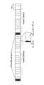
- Radio frame configuration studied in 5G Next, a radio frame configuration studied in 5G will be described. 5G is also assumed to use a radio frame configuration in which the time axis is divided by a predetermined time interval (subframe), as in LTE. In 5G, introduction of a flexible subframe that supports dynamic TDD and can change the usage of subframes (for DL, UL, etc.) in various ways is being studied.
- FIG. 2 is a diagram illustrating an example of a radio frame configuration that is being studied in 5G.
- the flexible subframe has information indicating the use of the subframe (DL data / UL data / reference signal / D2D data, etc.) in the DL control channel (DL Control) mapped at the head of the subframe.
- DL Control DL control channel
- the flexible subframe is mainly considered on the assumption that it is used for transmitting / receiving a signal or a data signal for a specific user apparatus UE (unicast / multicast).
- a predetermined cycle as a periodic subframe for transmitting (broadcasting) a signal that the user apparatus UE should receive in common for initial connection or the like, such as a synchronization signal and broadcast information, etc. It is under consideration to set a fixed subframe (Fixed DL subframe).
- the fixed subframe has been studied on the assumption that it is set with a relatively longer period than the flexible subframe.
- Radio parameters being studied in 5G will be described.
- 5G in order to realize a transmission rate of 10 Gbps or higher, a high frequency will be supported in addition to a wide band from several hundred MHz to 1 GHz or more. Therefore, as shown in FIG. 3, it has been studied that various radio parameters such as the subcarrier interval and the symbol length can be changed.
- the example on the right side of FIG. 3 is assumed to be applied to a carrier having a higher frequency than the example on the left side of FIG. 3, and the tolerance to phase noise is increased by widening the subcarrier spacing, and instead an OFDM symbol.
- the length can be shortened.
- FIG. 4 is a diagram illustrating an example of a configuration of the wireless communication system according to the embodiment.
- the radio communication system according to the embodiment includes a base station 1 and a user apparatus UE. Although one base station 1 and one user apparatus UE are shown in FIG. 4, this is an example, and there may be a plurality of each.
- the user apparatus UE has a function of communicating with the base station 1 and uses a reference signal transmitted from the base station 1 (hereinafter referred to as “RS (Reference Signal)”) and / or DL reception quality and / or Alternatively, it has a function of measuring channel information and reporting it to the base station 1.
- RS Reference Signal
- the base station 1 supports Massive MIMO and has a function of communicating with the user apparatus UE by performing beamforming. Further, the base station 1 has a function of selecting an appropriate beam used for communication based on the reception quality and / or channel information reported from the user apparatus UE.
- the base station 1 may be the above-described full digital Massive MIMO base station, a hybrid Massive MIMO base station, or an analog Massive MIMO base station. Note that the base station 1 according to the present embodiment is not necessarily required to support Massive MIMO. This embodiment may be a base station that does not support Massive MIMO.
- the base station 1 and the user apparatus UE may support both LTE and 5G NewRAT, or may support only 5G NewRAT.
- the base station 1 and the user apparatus UE support the radio frame configuration described in FIG. 2, and the base station 1 and the user apparatus UE can perform communication using a flexible subframe and a fixed subframe. . Moreover, the base station 1 and the user apparatus UE can support various radio parameters described with reference to FIG.
- FIG. 5 is a sequence diagram illustrating an example of a processing procedure performed by the wireless communication system according to the embodiment.
- the first RS and the second RS are used as the RS.
- the first RS and the second RS may be generated using different sequences, or may be generated using the same sequence.
- the base station 1 transmits the first RS in a fixed subframe (S11).
- the first RS is an RS group in which each of the RSs associated with different antenna ports is time-multiplexed (TDM) and transmitted.
- TDM time-multiplexed
- each RS included in the RS group may also be referred to as a “first RS”.
- the user apparatus UE measures the DL reception quality and / or channel state using the first RS received in the fixed subframe and reports it to the base station 1 (S12). More specifically, the user apparatus UE measures the DL reception quality and / or channel state for each first RS associated with each antenna port and reports it to the base station 1. Note that the user apparatus UE has the position of the radio resource to which the first RS is mapped (mapping pattern of the first RS) and the explicit notification from the base station 1 or by the implicit method according to the standard definition. This is a premise of grasping the first RS series and the like.
- the base station 1 transmits the second to be transmitted to the user apparatus UE based on the reception quality and / or channel state for each first RS associated with each antenna port reported from the user apparatus UE.
- the RS is selected, and the selected second RS is transmitted in a flexible subframe (S13).
- the second RS is an RS group associated with an antenna port different from the antenna port associated with the first RS.
- each RS included in the RS group may also be referred to as a “second RS”.
- the second RS is transmitted after being variously multiplexed using frequency multiplexing (FDM), code multiplexing (CDM), or time multiplexing (TDM).
- FDM frequency multiplexing
- CDM code multiplexing
- TDM time multiplexing
- the user apparatus UE measures the DL reception quality and / or channel state using the second RS received in the flexible subframe, and reports it to the base station 1 (S14). More specifically, the user apparatus UE measures the DL reception quality and / or channel state for each second RS associated with each antenna port and reports it to the base station 1.
- the user apparatus UE according to the standard definition, by the explicit notification from the base station 1 or by the implicit method, the position of the radio resource to which the second RS is mapped (mapping pattern of the second RS) and This is a premise that the second RS series or the like is known in advance.
- the base station 1 is used for communication with the user apparatus UE based on the reception quality and / or channel state of each second RS associated with each antenna port reported from the user apparatus UE.
- An appropriate beam is selected, and communication with the user apparatus UE is performed using the selected beam.
- the mapping pattern of the first RS that indicates the position of the radio resource to which the first RS corresponding to each antenna port is mapped will be described in detail.
- the first RS is transmitted in a fixed subframe. That is, the first RS is transmitted (broadcast) in common to all user apparatuses UE in the cell.
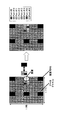
- FIG. 6 is a diagram showing a mapping example of the first RS.
- One grid shown in FIG. 6 (the same applies to FIGS. 7 to 9) is intended for radio resources (corresponding to LTE resource elements) composed of one subcarrier and one symbol. Not limited.
- the time axis of one grid shown in FIG. 6 may be a plurality of symbols or one subframe.
- the first RS is continuously transmitted in a plurality of subframes. Therefore, the fixed subframe is also continuously transmitted in a plurality of subframes. become.
- the frequency axis of one grid shown in FIG. 6 may be a plurality of subcarriers, one or a plurality of RBs (resource blocks), or another unit.
- the first RS is transmitted by time-multiplexing (TDM) the RS corresponding to each antenna port (antenna ports # 1 to # 8 in the example of FIG. 6). That is, the base station 1 transmits the first RS while sequentially switching the antenna ports as time passes. This is because it is assumed that the base station 1 transmits the first RS corresponding to each beam while sequentially switching the beam direction (phase) transmitted by analog beam forming according to the passage of time. is there. Note that in the case of a hybrid Massive MIMO base station and a full digital Massive MIMO base station, a plurality of beams can be generated at a certain time.
- TDM time-multiplexing
- the first RS is not limited to the case where it is completely time-multiplexed and transmitted for each antenna port, and RSs corresponding to a plurality of antenna ports may be frequency-multiplexed at a certain time.
- each user apparatus UE does not need to recognize which form the form of beam forming is.
- FIG. 6A shows an example in which RSs corresponding to the same antenna port are frequency-multiplexed and mapped to the upper and lower resources of the synchronization signal, and in the example of FIG. 6B, the same antenna is used.
- the RS corresponding to the port is mapped to the upper and lower resources of the synchronization signal by being frequency-multiplexed at a position shifted by a predetermined frequency from the synchronization signal.
- the synchronization signal is assumed to be transmitted at the center of the system bandwidth as in LTE, but is not necessarily limited thereto. This embodiment can also be applied to the case where the synchronization signal is transmitted at a position shifted from the center of the system bandwidth.
- the antenna port to which the synchronization signal is transmitted and the antenna port to which the first RS is transmitted may be the same at the same time.
- the synchronization signal transmitted at the time when the first RS is transmitted at antenna port # 1 may be a synchronization signal transmitted from antenna port # 1.
- the mapping pattern of the first RS may change (shift) every transmission cycle.
- the order in which the first RS is mapped in each transmission cycle can be realized by calculating from a predetermined index value that changes (shifts) for each transmission cycle.
- the predetermined index value may be, for example, a subframe number and / or SFN (System Frame Number).
- the mapping pattern of the first RS may be the same or different between cells.
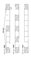
- An example in which the mapping pattern of the first RS is different between cells is shown in FIG. FIG. 7A shows an example of mapping in cell # 1, and FIG. 7B shows an example of mapping in cell # 2.
- the mapping pattern of the first RS different between cells at a certain time, for example, the position of the radio resource to which the first RS is mapped in each transmission cycle changes (shifts) for each transmission cycle. It can be realized by making it possible to calculate from a predetermined index value and cell ID.
- the resource to which the first RS is not mapped may be blank (that is, a resource to which no radio signal is transmitted).
- the base station 1 may boost the transmission power of the first RS by using the remaining transmission power for transmission of the first RS by providing a blank resource.
- the user apparatus UE may perform interference wave estimation with a blank resource. By setting blank resources at different positions between cells, the user apparatus UE can measure interference waves from other cells in the blank cells.
- the first RS may also serve as a synchronization signal.
- a mapping example of the first RS in this case is shown in FIG. In this case, the first RS can be mapped to the center of the system bandwidth, and it is not necessary to transmit both the synchronization signal and the first RS mainly on the base station 1 side. Side processing overhead can be reduced.
- the transmission cycle of the first RS may be defined in the standard specification, or notified (set) from the base station 1 to the user apparatus UE using broadcast information or a signaling message (for example, RRC message) specific to the user apparatus UE. You may be made to do. Further, notification (setting) may be made from the base station 1 to the user apparatus UE by MAC signaling or PHY (physical layer) signaling.
- the base station 1 may change the transmission period of the first RS by transmitting the first RS with only a part of the fixed subframe instead of the whole, or change the transmission interval of the fixed subframe. By doing so, you may make it change the transmission period of 1st RS.
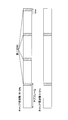
- the transmission period of the first RS may be set according to the carrier frequency, the subcarrier interval, and / or the average moving speed of the user apparatus UE assumed for the carrier.
- FIG. 10 shows an example in which different transmission periods are set for a carrier with a carrier frequency of 30 GHz and a carrier with a carrier frequency of 6 GHz.
- the user apparatus UE may recognize the transmission cycle of the first RS by notification (setting) from the base station 1, or implicitly recognize based on the system bandwidth, the carrier frequency, or the like. You may do it.
- the base station 1 may dynamically change the transmission cycle of the first RS, for example, 10 ms in one period and 5 ms in the next period, or a predetermined trigger may be set. You may make it change semi-statically with an opportunity. In this case, the base station 1 may notify the user apparatus UE in advance which transmission cycle is applied in which period, and the changed transmission cycle may be broadcast information or individual user apparatus UE. May be set in the user apparatus UE using a signaling message (for example, RRC message).
- a signaling message for example, RRC message
- a plurality of periodic patterns are defined in advance as the transmission period of the first RS, and the base station 1 may transmit the first RS with any periodic pattern.
- the first RS uses a different sequence for each of the plurality of periodic patterns so that the user apparatus UE can perform blind detection on which periodic pattern the first RS is transmitted. May be transmitted. Thereby, the user apparatus UE can blind-detect which periodic pattern is transmitting 1st RS by specifying the series of 1st RS.
- the mapping pattern of the first RS may be defined in the standard specification, and is notified (set) from the base station 1 to the user apparatus UE using broadcast information or a signaling message specific to the user apparatus UE (for example, RRC message). You may be made to do. Further, notification (setting) may be made from the base station 1 to the user apparatus UE by MAC signaling or PHY (physical layer) signaling. The first RS sequence may also be defined in the standard specification, and notified (set) from the base station 1 to the user apparatus UE using broadcast information or a signaling message specific to the user apparatus UE (for example, an RRC message). You may be made to do. Further, notification (setting) may be made from the base station 1 to the user apparatus UE by MAC signaling or PHY (physical layer) signaling.
- mapping pattern a different mapping pattern may be set according to the carrier frequency, the subcarrier interval, and / or the average moving speed of the user apparatus UE assumed for the carrier.
- the base station 1 may change the mapping pattern dynamically, for example, mapping pattern A in a certain period and mapping pattern B in the next period, or triggered by a predetermined trigger. You may make it change semi-statically. In this case, the base station 1 may notify the user apparatus UE in advance which mapping pattern is applied in which period, or the changed mapping pattern may be broadcast information or individual user apparatus UE. May be set in the user apparatus UE using a signaling message (for example, RRC message).
- a signaling message for example, RRC message
- a plurality of mapping patterns may be defined in advance as the mapping pattern of the first RS, and the base station 1 may transmit the first RS with any mapping pattern.
- the first RS uses a different sequence for each of the plurality of mapping patterns so that the user apparatus UE can perform blind detection on which mapping pattern the first RS is transmitted. May be transmitted. Accordingly, the user apparatus UE can blind detect which mapping pattern is used to transmit the first RS by specifying the first RS sequence.
- the user apparatus UE measures the DL reception quality and / or channel state for each first RS associated with each antenna port, and determines an uplink control channel (uplink control information). ) To the base station 1.
- the user apparatus UE may collectively report the measurement results for all antenna ports to the base station 1 or may appropriately report for each antenna port for which measurement has been completed.
- the reception quality may be RSRQ, RSRP, RSSI, SINR, or a part or all of these.
- the user apparatus UE may report only measurement results corresponding to some antenna ports to the base station 1 instead of reporting all measurement results corresponding to all antenna ports to the base station 1. Good.
- the antenna port to be reported may be explicitly instructed to the user apparatus UE from the base station 1, or the antenna port to be reported may be selected by the user apparatus UE itself. In the latter case, the user apparatus UE may report the reception quality by focusing on the antenna port whose reception quality is equal to or higher than a predetermined threshold.
- the user apparatus UE may report the average value of the measurement results in a predetermined time interval to the base station 1. For example, when the first RS is transmitted at a period of 10 ms and the predetermined time interval is 30 ms, the user apparatus UE receives the DL reception quality for each first RS associated with each antenna port and The channel state is measured over three periods, and the measured reception quality and / or average value of the channel state for each antenna port is reported to the base station 1 for each antenna port.
- the length of the predetermined time interval may be defined in the standard specification, or notified (set) from the base station 1 to the user apparatus UE using broadcast information or a signaling message specific to the user apparatus UE (for example, an RRC message). You may be made to do. Further, notification (setting) may be made from the base station 1 to the user apparatus UE by MAC signaling or PHY (physical layer) signaling.
- the length of the predetermined time interval may be set to a different time interval according to the carrier frequency, the subcarrier interval, the average moving speed of the user apparatus UE assumed for the carrier, and the like. .
- the length of the predetermined time interval may be dynamically changed, for example, “30 ms” in a certain period and “50 ms” in the next period, or may be semi-statically triggered by a predetermined trigger. You may make it change to.
- a plurality of patterns may be defined in advance as the length of the predetermined time interval, and the user apparatus UE may be able to perform blind detection on which pattern the measurement result is averaged and reported.
- the first RS may be transmitted using a different sequence for each of the plurality of patterns. Thereby, the user apparatus UE can perform blind detection on which pattern the measurement result is averaged and reported by specifying the first RS sequence.
- the user apparatus UE may select the length of a predetermined time interval in which the measurement results are averaged.
- the antenna that measures the first RS by measuring the reception quality using the synchronization signal transmitted in the fixed subframe. You may make it throttle a port beforehand. In this case, the synchronization signal needs to be transmitted in association with each antenna port.
- the mapping pattern of the second RS that indicates the position of the radio resource to which the second RS corresponding to each antenna port is mapped will be specifically described.
- the second RS is transmitted in a flexible subframe.
- the second RS may be individually transmitted (unicast) to each user apparatus UE, or may be commonly transmitted (broadcast) to all user apparatuses UE in the cell.
- FIG. 12 is a diagram illustrating a mapping example of the second RS.
- the RS corresponding to each antenna port (antenna ports # 9 to # 16 in the example of FIG. 12) different from the first RS is frequency multiplexed (FDM) and code multiplexed (CDM). ) And / or time multiplexed (TDM).
- the unit region is assumed to be a region surrounded by 1 RB in the frequency direction and 1 TTI in the time direction. However, the unit region is not limited to this, and there may be a plurality of RBs in the frequency direction and a plurality of TTIs in the time direction.
- FIG. 12A shows a case where the second RS is frequency-multiplexed
- FIG. 12B shows a case where the second RS is frequency-multiplexed and code-multiplexed
- FIG. FIG. 12D shows a case where the second RS shown in FIG. 12C is multiplexed for a plurality of times.
- the mapping pattern of the second RS may change (shift) every transmission cycle.
- the order in which the second RS is mapped in each transmission cycle can be realized by calculating from a predetermined index value that changes (shifts) for each transmission cycle.
- the predetermined index value may be, for example, a subframe number and / or SFN (System Frame Number).
- the mapping pattern of the second RS may be the same or different between cells.
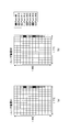
- An example in which the order in which the second RS corresponding to each antenna port is mapped in each transmission period differs between cells is shown in FIG.
- FIG. 13A shows an example of mapping in cell # 1
- FIG. 13B shows an example of mapping in cell # 2.
- the mapping pattern of the second RS may be common within the cell, or may be different for each user apparatus UE.
- FIG. 14 shows a case where the mapping pattern of the second RS is common in the cell, and FIG. 14A shows the mapping pattern of the second RS for the user apparatus UE # 1, FIG. Indicates a mapping pattern of the second RS for user apparatus UE # 2.
- FIG. 15 shows a case where the mapping pattern of the second RS is different for each user apparatus UE, and FIG. 15A shows the mapping pattern of the second RS for the user apparatus UE # 1, FIG. Is the second RS mapping pattern for user apparatus UE # 2, and
- FIG. 15C shows the second RS mapping pattern for user apparatus UE # 3.
- the second RS and the downlink data channel may be multiplexed.
- the symbol to which the data channel is mapped and the symbol to which the second RS is mapped are clearly defined. They may be distinguished or may be mixed as shown in FIG.
- the second RS and the downlink data channel are multiplexed, the second RS is mapped to the second half of the plurality of symbols in the unit area, for example, at least the last symbol. It may be.
- the user apparatus UE can decode the data channel prior to the measurement of the second RS, and can shorten the DL transmission delay.
- the resource position of the demodulation RS (DMRS) mapped to the downlink data channel and the resource to which the second RS is mapped It is assumed that the position overlaps. Therefore, in the present embodiment, the resource position of the demodulation RS and the resource position of the second RS may be defined separately so that no duplication occurs in the first place.
- the RS mapping method may be changed according to a predetermined rule.
- the change rule at the time of duplication may be prescribed
- the signaling may be a method of indexing a plurality of change rules and notifying their values.
- FIG. 17 shows an example in which the position of the second RS is shifted when the resource position of the demodulation RS and the resource position of the second RS overlap.
- FIG. 18 illustrates an example in which the position of the demodulation RS is shifted when the resource position of the demodulation RS and the resource position of the second RS overlap.
- FIG. 19 shows an example in which when the resource position of the demodulation RS and the resource position of the second RS overlap, priority is given to the transmission of the second RS and the demodulation RS is not transmitted (dropped). Yes. Note that, when the resource position of the demodulation RS and the resource position of the second RS overlap, priority may be given to transmission of the demodulation RS, and the second RS may not be transmitted (dropped). Further, when performing the process of dropping the demodulation RS or the second RS, the base station 1 may perform the puncturing.
- a resource to which the second RS is not mapped may be blank (that is, a resource to which no radio signal is transmitted).
- the base station 1 may boost the transmission power of the second RS by using the remaining transmission power for transmission of the second RS by providing a blank resource, or the data channel. May be assigned.
- the user apparatus UE may perform interference wave estimation with a blank resource. By setting blank resources at different positions between cells, the user apparatus UE can measure interference waves from other cells in the blank cells.
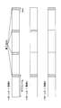
- the transmission cycle of the second RS may be common (broadcast transmission) in the cell as shown in FIG. 21, or may be different (unicast transmission) in each user apparatus UE as shown in FIG. It may be.
- the transmission period of the second RS may be defined in the standard specification, or notified (set) from the base station 1 to the user apparatus UE using broadcast information or a signaling message specific to the user apparatus UE (for example, an RRC message). You may be made to do. Further, notification (setting) may be made from the base station 1 to the user apparatus UE by MAC signaling or PHY (physical layer) signaling.
- the transmission period of the second RS may be set according to the carrier frequency, the subcarrier interval, the average moving speed of the user apparatus UE assumed for the carrier, and the like.
- FIG. 23 shows an example in which different transmission periods are set for a carrier with a carrier frequency of 30 GHz and a carrier with a carrier frequency of 6 GHz.
- the user apparatus UE may recognize the transmission period of the second RS by notification (setting) from the base station 1, or implicitly recognize based on the system bandwidth, the carrier frequency, or the like. You may do it.
- implicitly recognizing it is possible to increase frequency utilization efficiency by reducing signaling.
- the base station 1 may dynamically change the transmission cycle of the second RS, for example, 10 ms in a certain period and 5 ms in the next period, or a predetermined trigger may be set. You may make it change semi-statically with an opportunity. In this case, the base station 1 may notify the user apparatus UE in advance which transmission cycle is applied in which period, and the changed transmission cycle may be broadcast information or individual user apparatus UE. May be set in the user apparatus UE using a signaling message (for example, RRC message).
- a signaling message for example, RRC message
- a plurality of periodic patterns are defined in advance as the transmission period of the second RS, and the base station 1 may transmit the second RS with any periodic pattern.
- the second RS uses a different sequence for each of the plurality of periodic patterns so that the user apparatus UE can blindly detect which periodic pattern is used to transmit the second RS. May be transmitted. Thereby, the user apparatus UE can blind-detect which periodic pattern is transmitting 2nd RS by specifying the series of 2nd RS.
- the base station 1 may transmit the second RS when the user apparatus UE measures the second RS.
- the base station 1 sets information for specifying the mapping pattern of the second RS corresponding to each antenna port in a predetermined bit of downlink control information (DL Control Information) transmitted in the flexible subframe.
- DL Control Information downlink control information
- the mapping pattern may be notified to the user apparatus UE.
- the user apparatus UE may report the measurement result to the base station 1 at a predetermined timing, or may transmit the measurement result when the uplink data channel is scheduled by the UL grant.
- the mapping pattern of the second RS may be defined in the standard specification, and is notified (set) from the base station 1 to the user apparatus UE using broadcast information or a signaling message specific to the user apparatus UE (for example, RRC message). You may be made to do. Further, notification (setting) may be made from the base station 1 to the user apparatus UE by MAC signaling or PHY (physical layer) signaling. The second RS sequence may also be defined in the standard specification, and notified (set) from the base station 1 to the user apparatus UE using broadcast information or a signaling message (for example, RRC message) specific to the user apparatus UE. You may be made to do. Further, notification (setting) may be made from the base station 1 to the user apparatus UE by MAC signaling or PHY (physical layer) signaling.
- mapping pattern a different mapping pattern may be set according to the carrier frequency, the subcarrier interval, the average moving speed of the user apparatus UE assumed for the carrier, and the like. This makes it possible to perform desired measurement while suppressing deterioration of frequency utilization efficiency even under various conditions.
- the base station 1 may change the mapping pattern dynamically, for example, mapping pattern A in a certain period and mapping pattern B in the next period, or triggered by a predetermined trigger. You may make it change semi-statically. In this case, the base station 1 may notify the user apparatus UE in advance which mapping pattern is applied in which period, or the changed mapping pattern may be broadcast information or individual user apparatus UE. May be set in the user apparatus UE using a signaling message (for example, RRC message).
- a signaling message for example, RRC message
- a plurality of mapping patterns may be defined in advance as the mapping pattern of the second RS, and the base station 1 may transmit the second RS with any mapping pattern.
- the second RS uses a different sequence for each of the plurality of mapping patterns so that the user apparatus UE can perform blind detection on which mapping pattern the second RS is transmitted. May be transmitted. Accordingly, the user apparatus UE can blind detect which mapping pattern is used to transmit the second RS by specifying the second RS sequence.
- the user apparatus UE measures the DL reception quality and / or channel state for each second RS associated with each antenna port, and determines an uplink control channel (uplink control information). ) To the base station 1.
- the user apparatus UE may collectively report the measurement results for all antenna ports to the base station 1 or may appropriately report for each antenna port for which measurement has been completed.
- the reception quality may be RSRQ, RSRP, RSSI, SINR, or a part or all of these.
- the user apparatus UE may report only measurement results corresponding to some antenna ports to the base station 1 instead of reporting all measurement results corresponding to all antenna ports to the base station 1. Good.
- the antenna port to be reported may be explicitly instructed to the user apparatus UE from the base station 1, or the antenna port to be reported may be selected by the user apparatus UE itself. In the latter case, the user apparatus UE may report the reception quality by focusing on the antenna port whose reception quality is equal to or higher than a predetermined threshold.
- the user apparatus UE may report the average value of the measurement results in a predetermined time interval to the base station 1. For example, when the second RS is transmitted at a period of 10 ms and the predetermined time interval is 30 ms, the user apparatus UE receives the DL reception quality for each second RS associated with each antenna port and The channel state is measured over three periods, and the measured reception quality and / or average value of the channel state for each antenna port is reported to the base station 1 for each antenna port.
- the length of the predetermined time interval may be defined in the standard specification, or notified (set) from the base station 1 to the user apparatus UE using broadcast information or a signaling message specific to the user apparatus UE (for example, an RRC message). You may be made to do. Further, notification (setting) may be made from the base station 1 to the user apparatus UE by MAC signaling or PHY (physical layer) signaling.
- the length of the predetermined time interval may be set to a different time interval according to the carrier frequency, the subcarrier interval, the average moving speed of the user apparatus UE assumed for the carrier, and the like. .
- the length of the predetermined time interval may be dynamically changed, for example, “30 ms” in a certain period and “50 ms” in the next period, or may be semi-statically triggered by a predetermined trigger. You may make it change to.
- a plurality of patterns may be defined in advance as the length of the predetermined time interval, and the user apparatus UE may be able to perform blind detection on which pattern the measurement result is averaged and reported.
- the second RS may be transmitted using a different series in each of the plurality of patterns. Thereby, the user apparatus UE can perform blind detection on which pattern the measurement result is averaged and reported by specifying the second RS sequence.
- the user apparatus UE may select the length of a predetermined time section by itself.
- the reception quality is measured using the synchronization signal transmitted in the fixed subframe, or the reception of the first RS You may make it narrow down beforehand the antenna port which measures 2nd RS using the measurement result of quality.
- the mapping pattern of the first RS “the transmission period of the first RS”, “the sequence of the first RS”, “the predetermined time interval in which the measurement results of the first RS are averaged” “Length”, “second RS mapping pattern”, “second RS transmission period”, “second RS sequence”, or “predetermined time interval for averaging the measurement results of the second RS”
- the base station 1 to the user apparatus UE by broadcast information, RRC signaling, MAC signaling or PHY signaling, so that the setting value itself is notified (set) from the base station 1 to the user apparatus UE.
- an index value associated in advance for each set value pattern may be notified (set) from the base station 1 to the user apparatus UE. As a result, the amount of signaling can be reduced.
- the base station 1 uses the first RS mapping pattern described with reference to FIGS. 6 to 8 (that is, the pattern in which the synchronization signal and the first RS are transmitted in a fixed subframe) and FIG.
- the first RS mapping pattern described above (the pattern in which the first RS also serves as a synchronization signal) may be used in combination.
- the base station 1 applies the mapping pattern of the first RS described with reference to FIGS. 6 to 8 in a certain time zone, and maps the first RS described with reference to FIG. 9 in other time zones.
- a pattern may be applied.
- the base station 1 sets the mapping pattern of the 1st RS applied for every time slot
- the user apparatus UE may use the first RS or the second RS when performing the synchronization process (time synchronization and frequency synchronization).
- the base station 1 uses the analog beam forming to set the first RS associated with five beams (for example, antenna ports # 1 to # 5) in a fixed subframe. Send. Note that the base station 1 does not transmit the five beams at the same time but transmits the beams while sequentially switching the beams as time passes.
- five beams for example, antenna ports # 1 to # 5
- the user apparatus UE reports the measurement result to the base station 1 for each first RS associated with the antenna ports # 1 to # 5.
- the base station 1 roughly determines the beam direction based on the measurement result (for example, received power) for each first RS reported from the user apparatus UE.
- the base station 1 uses a combination of analog beam forming and digital beam forming in the vicinity of the determined rough beam direction.
- the second RS associated with the beam (for example, antenna ports # 11 to 15) is transmitted in the flexible subframe. Note that the base station 1 notifies the user apparatus UE in advance of which flexible subframe to transmit the second RS using RRC signaling or the like.
- the user apparatus UE reports the measurement result to the base station 1 for each second RS associated with the antenna ports # 10 to # 15. Subsequently, the base station 1 determines the final beam direction based on the measurement result (for example, received power) for each second RS reported from the user apparatus UE. Note that the base station 1 may instruct the user apparatus UE to periodically report measurement results for the first RS and the second RS. Thereby, even if it is a case where the user apparatus UE moves, the direction of a beam can be made to follow.
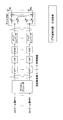
- FIG. 26 is a diagram illustrating an example of a functional configuration of the base station according to the embodiment.
- the base station 1 includes a signal transmission unit 101, a signal reception unit 102, a setting unit 103, and a control unit 104.
- FIG. 26 shows only functional units particularly related to the embodiment of the present invention in the base station 1, and also has a function (not shown) for performing an operation based on at least 5G (including LTE). It is.
- the functional configuration illustrated in FIG. 26 is merely an example. As long as the operation according to the present embodiment can be executed, the function classification and the name of the function unit may be anything.
- the signal transmission unit 101 includes a function of generating various physical layer signals from the upper layer signal to be transmitted from the base station 1 and wirelessly transmitting the signals. Moreover, the signal transmission part 101 has a function which transmits 1st RS and 2nd RS.
- the signal receiving unit 102 includes a function of receiving various radio signals from the user apparatus UE and acquiring a higher layer signal from the received physical layer signal.
- the setting unit 103 has a function of setting various information used for the user apparatus UE to perform the operation according to the present embodiment in the user apparatus UE using broadcast information or RRC signaling.
- the various information includes, for example, “first RS mapping pattern”, “first RS transmission cycle”, “first RS sequence”, “predetermined average of first RS measurement results” The time interval of “second”, “mapping pattern of second RS”, “transmission period of second RS”, “sequence of second RS”, and / or “measurement result of second RS” The length of a predetermined time interval to be averaged.
- the control unit 104 has a function of controlling the beam direction based on the measurement result reported from the user apparatus UE. Moreover, the control part 104 has a function which determines and changes the period which transmits 1st RS and 2nd RS, and the mapping pattern of 1st RS and 2nd RS.
- FIG. 27 is a diagram illustrating an example of a functional configuration of the user apparatus according to the embodiment.
- the user apparatus UE includes a signal transmission unit 201, a signal reception unit 202, an RS configuration management unit 203, a measurement unit 204, and a report unit 205.
- FIG. 27 shows only the functional units particularly related to the embodiment of the present invention in the user apparatus UE, and also has a function (not shown) for performing an operation based on at least 5G (including LTE). It is.
- the functional configuration illustrated in FIG. 27 is merely an example. As long as the operation according to the present embodiment can be executed, the function classification and the name of the function unit may be anything.
- the signal transmission unit 201 includes a function of generating various types of physical layer signals from a higher layer signal to be transmitted from the user apparatus UE and wirelessly transmitting the signals.
- the signal receiving unit 202 includes a function of wirelessly receiving various signals from the base station 1 and acquiring higher layer signals from the received physical layer signals.
- the RS configuration management unit 203 is defined in the standard specifications, or is set by broadcast information, RRC signaling, MAC signaling or PHY signaling, “first RS mapping pattern”, “first RS transmission cycle” , “First RS sequence”, “the length of a predetermined time interval in which the measurement results of the first RS are averaged”, “mapping pattern of the second RS”, “transmission cycle of the second RS”, It has a function of managing “second RS series” and “the length of a predetermined time interval in which the measurement results of the second RS are averaged”.
- the measurement unit 204 manages the “first RS mapping pattern”, “first RS transmission cycle”, “first RS sequence”, “second RS management” managed by the RS configuration management unit 203. Based on the “mapping pattern”, “transmission cycle of the second RS”, and “sequence of the second RS”, the radio resource to which the first RS is transmitted and the radio resource to which the second RS is transmitted Recognizing and measuring the reception quality and / or channel condition.
- the measurement unit 204 includes a first measurement unit 2041 and a second measurement unit 2042.
- the first measurement unit 2041 uses the first RS transmitted in a periodically set time interval (fixed subframe) among radio frames divided by a predetermined time interval, and / or reception quality and / or It has a function to measure the channel state.
- the second measurement unit 2042 transmits the first frame transmitted in an arbitrary time interval (flexible subframe) other than the periodically set time interval (fixed subframe) among the radio frames divided by the predetermined time interval.
- the second RS has a function of measuring reception quality and / or channel state.
- the reporting unit 205 has a function of reporting the reception quality or channel information measured using the first RS and the reception quality or channel information measured using the second RS to the base station 1.
- each functional block may be realized by one device physically and / or logically coupled, and two or more devices physically and / or logically separated may be directly and / or indirectly. (For example, wired and / or wireless) and may be realized by these plural devices.
- the base station 1 and the user apparatus UE in an embodiment of the present invention may function as a computer that performs processing of the measurement method of the present invention.
- FIG. 28 is a diagram illustrating an example of a hardware configuration of the base station 1 and the user apparatus UE according to the embodiment.
- the base station 1 and the user apparatus UE described above may be physically configured as a computer apparatus including a processor 1001, a memory 1002, a storage 1003, a communication apparatus 1004, an input apparatus 1005, an output apparatus 1006, a bus 1007, and the like. .
- the term “apparatus” can be read as a circuit, a device, a unit, or the like.
- the hardware configuration of the base station 1 and the user apparatus UE may be configured to include one or a plurality of the apparatuses illustrated in the figure, or may be configured not to include some apparatuses.
- Each function in the base station 1 and the user apparatus UE is obtained by reading predetermined software (program) on hardware such as the processor 1001 and the memory 1002, so that the processor 1001 performs calculation, communication by the communication apparatus 1004, and memory This is realized by controlling reading and / or writing of data in the storage 1003.
- the processor 1001 controls the entire computer by operating an operating system, for example.
- the processor 1001 may be configured by a central processing unit (CPU) including an interface with peripheral devices, a control device, an arithmetic device, a register, and the like.
- CPU central processing unit
- the measurement unit 204 and the report unit 205 may be realized by the processor 1001.
- the processor 1001 reads a program (program code), software module, or data from the storage 1003 and / or the communication device 1004 to the memory 1002, and executes various processes according to these.
- a program program that causes a computer to execute at least a part of the operations described in the above embodiments is used.
- the measurement unit 204 and the report unit 205 may be realized by a control program stored in the memory 1002 and operated by the processor 1001, and may be realized similarly for other functional blocks.
- processor 1001 may be executed simultaneously or sequentially by two or more processors 1001.
- the processor 1001 may be implemented by one or more chips. Note that the program may be transmitted from a network via a telecommunication line.
- the memory 1002 is a computer-readable recording medium, and includes, for example, at least one of ROM (Read Only Memory), EPROM (Erasable Programmable ROM), EEPROM (Electrically Erasable Programmable ROM), RAM (Random Access Memory), and the like. May be.
- the memory 1002 may be called a register, a cache, a main memory (main storage device), or the like.
- the memory 1002 can store programs (program codes), software modules, and the like that can be executed to implement the measurement method according to the embodiment of the present invention.
- the storage 1003 is a computer-readable recording medium such as an optical disk such as a CD-ROM (Compact Disc ROM), a hard disk drive, a flexible disk, a magneto-optical disk (for example, a compact disk, a digital versatile disk, a Blu-ray). (Registered trademark) disk, smart card, flash memory (for example, card, stick, key drive), floppy (registered trademark) disk, magnetic strip, and the like.
- the storage 1003 may be referred to as an auxiliary storage device.
- the storage medium described above may be, for example, a database, server, or other suitable medium including the memory 1002 and / or the storage 1003.
- the communication device 1004 is hardware (transmission / reception device) for performing communication between computers via a wired and / or wireless network, and is also referred to as a network device, a network controller, a network card, a communication module, or the like.
- a network device for example, the signal transmission unit 101 and the signal reception unit 102 of the base station 1 and the signal transmission unit 201 and the signal reception unit 202 of the user apparatus UE may be realized by the communication device 1004.
- the input device 1005 is an input device (for example, a keyboard, a mouse, a microphone, a switch, a button, a sensor, etc.) that accepts an input from the outside.
- the output device 1006 is an output device (for example, a display, a speaker, an LED lamp, etc.) that performs output to the outside.
- the input device 1005 and the output device 1006 may have an integrated configuration (for example, a touch panel).
- each device such as the processor 1001 and the memory 1002 is connected by a bus 1007 for communicating information.
- the bus 1007 may be configured with a single bus or may be configured with different buses between apparatuses.
- the base station 1 and the user equipment UE include hardware such as a microprocessor, a digital signal processor (DSP), an application specific integrated circuit (ASIC), a programmable logic device (PLD), and a field programmable gate array (FPGA). Hardware may be configured, and a part or all of each functional block may be realized by the hardware.
- the processor 1001 may be implemented by at least one of these hardware.
- a user apparatus in a radio communication system having a base station and a user apparatus, and transmitted in a time interval that is set periodically among radio frames divided in a predetermined time interval.
- a first measurement unit that measures reception quality or channel information using the first reference signal, and a radio frame that is divided by the predetermined time interval other than the periodically set time interval
- a second measurement unit that measures reception quality or channel information using a second reference signal transmitted in an arbitrary time interval; reception quality or channel information measured using the first reference signal;
- a user apparatus comprising: a report unit that reports reception quality or channel information measured using the second reference signal to the base station.
- a technique is provided in which the user apparatus can measure the reference signal and feed back the measurement result to the base station.
- the first reference signal may be transmitted by time-multiplexing each of the reference signals associated with different antenna ports. Thereby, the base station 1 can transmit 1st RS, switching a beam in order according to progress of time.
- the first reference signal may be transmitted in any one of a plurality of periodic patterns, and transmitted using a different sequence in each of the plurality of periodic patterns.
- the user apparatus UE can blind detect the cycle in which the first RS is transmitted.
- the second reference signal is transmitted by frequency multiplexing, code multiplexing or time multiplexing of a reference signal associated with a different antenna port, and the antenna port associated with the second reference signal is It may be different from the antenna port associated with one reference signal.
- the base station 1 can transmit the second RS by various multiplexing methods.
- the radio resource to which the second reference signal is transmitted in the arbitrary time interval may be notified by downlink control information transmitted from the base station in the arbitrary time interval. Accordingly, the base station 1 can dynamically notify the user apparatus UE of the second RS mapping pattern in units of subframes.
- the measurement method is performed by a user apparatus in a radio communication system having a base station and a user apparatus, and is set periodically among radio frames separated by a predetermined time interval.
- a step of measuring reception quality or channel information using a first reference signal transmitted in a predetermined time interval, and a radio frame delimited by the predetermined time interval other than the periodically set time interval Measuring reception quality or channel information using a second reference signal transmitted in an arbitrary time interval, receiving quality or channel information measured using the first reference signal, and the second Reporting reception quality or channel information measured using the reference signal to the base station.
- a technique is provided in which the user apparatus can measure the reference signal and feed back the measurement result to the base station.
- 1 RB in the frequency direction is 12 subcarriers and 1 TTI is 14 symbols, but the present invention is not limited to this.
- One RB in the frequency direction may have a number of subcarriers other than 12 subcarriers as a unit, or may have a number of symbols other than 14 symbols as a unit.
- the present embodiment has been described on the assumption that the number of first RS antenna ports and the number of antenna ports of the second RS are 8, respectively, the present invention is not limited to this.
- a value greater than 8 such as 16 may be used, and a value less than 8 such as 4 may be used.
- the subframe may be called a time interval.
- the fixed subframe may be referred to as a subframe or a time interval in which either one or both of the synchronization signal and the broadcast information are mapped.
- the flexible subframe may be referred to as a subframe or time interval in which a data signal is mapped.
- the beam may be referred to as an antenna port.
- Digital beam may be a general term for a collection of one or more antenna ports.
- the RS associated with the analog beam may be the first RS (first RS group), and the RS associated with the digital beam may be the second RS (second RS group).
- the PDSCH may be referred to as a downlink shared channel or a downlink data channel.
- the DMRS may be referred to as a data demodulation reference signal.
- the cell ID may be referred to as a cell specific index.
- the RB may be called a resource unit, a subband, a scheduling unit, or a frequency unit.
- the TTI may be referred to as a time unit or a subframe.
- PSS / SSS may be referred to as a first / second synchronization signal, or may be referred to as a synchronization signal without distinguishing between them.
- UCI Uplink Control Information
- the PUSCH may be referred to as a physical uplink shared channel or an uplink data channel.
- the PUCCH may be referred to as a physical uplink control channel or an uplink control channel.
- 1 RB has been described on the assumption that it is composed of 12 subcarriers based on an example of LTE.
- the present invention is not limited to this, and an RB composed of the number of subcarriers defined by 5G NewRAT. including.
- 1TTI has been described on the assumption that it is composed of 14 symbols based on the LTE example, but is not limited thereto, and includes a TTI length composed of a number of symbols defined by 5G NewRAT.
- information notification includes physical layer signaling (for example, DCI, UCI), upper layer signaling (for example, RRC signaling, MAC signaling, broadcast information (MIB (Master Information Block), SIB (System Information Block))), etc. Or a combination thereof.
- RRC signaling may be referred to as an RRC message, and may be, for example, an RRC connection setup (RRC Connection Setup) message, an RRC connection reconfiguration (RRC Connection Reconfiguration) message, or the like.
- Each aspect / embodiment described in this specification includes LTE, LTE-A (LTE-Advanced), SUPER 3G, IMT-Advanced, 4G, 5G, FRA (Future Radio Access), W-CDMA (registered trademark), GSM (registered trademark), CDMA2000, UMB (Ultra Mobile Broadband), IEEE 802.11 (Wi-Fi), IEEE 802.16 (WiMAX), IEEE 802.20, UWB (Ultra-WideBand), Bluetooth (registered trademark)
- the present invention may be applied to a system using other appropriate systems and / or a next-generation system extended based on these systems.
- the specific operation assumed to be performed by the base station in the present specification may be performed by the upper node in some cases.
- various operations performed for communication with the terminal may be performed by the base station and / or other network nodes other than the base station (e.g., Obviously, this can be done by MME or S-GW, but not limited to these.
- MME Mobility Management Entity
- S-GW Packet Control Function
- the input / output information or the like may be stored in a specific place (for example, a memory) or may be managed by a management table. Input / output information and the like can be overwritten, updated, or additionally written. The output information or the like may be deleted. The input information or the like may be transmitted to another device.
- the reference signal may be referred to as a pilot depending on the standard applied.
- the phrase “based on” does not mean “based only on”, unless expressly specified otherwise. In other words, the phrase “based on” means both “based only on” and “based at least on.”
- any reference to an element using a designation such as “first”, “second”, etc. as used herein does not generally limit the amount or order of those elements. These designations can be used herein as a convenient way to distinguish between two or more elements. Thus, a reference to the first and second elements does not mean that only two elements can be employed there, or that in some way the first element must precede the second element.
- the radio frame may be composed of one or a plurality of frames in the time domain. Each frame or frames in the time domain may be referred to as a subframe. A subframe may further be composed of one or more slots in the time domain. A slot may further be composed of one or more symbols (OFDM symbols, SC-FDMA symbols, etc.) in the time domain.
- the radio frame, subframe, slot, and symbol all represent a time unit when transmitting a signal. Radio frames, subframes, slots, and symbols may be called differently corresponding to each.
- the base station performs scheduling for allocating radio resources (frequency bandwidth and transmission power that can be used in each mobile station) to each mobile station.
- the minimum scheduling unit may be called TTI.
- TTI For example, one subframe may be called a TTI, a plurality of consecutive subframes may be called a TTI, and one slot may be called a TTI.
- a resource block is a resource allocation unit in the time domain and the frequency domain, and may include one or a plurality of continuous subcarriers in the frequency domain.
- one or a plurality of symbols may be included, and one slot, one subframe, or a length of 1 TTI may be included.
- One TTI and one subframe may each be composed of one or a plurality of resource blocks.
- the structure of the radio frame described above is merely an example, and the number of subframes included in the radio frame, the number of slots included in the subframe, the number of symbols and resource blocks included in the slots, and the subframes included in the resource block The number of carriers can be variously changed.
- the determination or determination may be performed by a value represented by 1 bit (0 or 1), may be performed by a true value (Boolean: true or false), or may be performed by comparing numerical values (for example, (Comparison with a predetermined value).
- the channel and / or symbol may be a signal.
- the signal may be a message.
- UE is a subscriber station, mobile unit, subscriber unit, wireless unit, remote unit, mobile device, wireless device, wireless communication device, remote device, mobile subscriber station, access terminal, mobile terminal, wireless terminal by those skilled in the art , Remote terminal, handset, user agent, mobile client, client, or some other appropriate terminology.
- notification of predetermined information is not limited to explicitly performed, but is performed implicitly (for example, notification of the predetermined information is not performed). Also good.
- determining may encompass a wide variety of actions.
- “Judgment”, “decision” can be, for example, calculating, computing, processing, deriving, investigating, looking up (eg, table, database or another (Searching in the data structure), and confirming (ascertaining) what has been confirmed may be considered as “determining” or “determining”.
- “determination” and “determination” include receiving (for example, receiving information), transmitting (for example, transmitting information), input (input), output (output), and access. (accessing) (e.g., accessing data in a memory) may be considered as “determined” or "determined”.
- determination and “decision” means that “resolving”, “selecting”, “choosing”, “establishing”, and “comparing” are regarded as “determining” and “deciding”. May be included. In other words, “determination” and “determination” may include considering some operation as “determination” and “determination”.
- the notification of the predetermined information is not limited to explicitly performed, and may be performed implicitly (for example, notification of the predetermined information is not performed). .
Landscapes
- Engineering & Computer Science (AREA)
- Signal Processing (AREA)
- Computer Networks & Wireless Communication (AREA)
- Quality & Reliability (AREA)
- Physics & Mathematics (AREA)
- Electromagnetism (AREA)
- Mobile Radio Communication Systems (AREA)
Abstract
L'invention concerne un dispositif utilisateur dans un système de communication sans fil comprenant une station de base et le dispositif utilisateur, le dispositif utilisateur comprenant : une première unité de mesure qui mesure la qualité de réception ou les informations de canal au moyen d'un premier signal de référence transmis dans un intervalle de temps défini périodiquement dans une trame sans fil divisée en intervalles de temps prescrits ; une seconde unité de mesure qui mesure la qualité de réception ou les informations de canal au moyen d'un second signal de référence transmis dans un intervalle de temps arbitraire différent de l'intervalle de temps défini périodiquement dans une trame sans fil divisée en intervalles de temps prescrits ; et une unité de notification qui notifie à la station de base la qualité de réception ou les informations de canal mesurées, au moyen du premier signal de référence et la qualité de réception ou les informations de canal mesurées, au moyen du second signal de référence.
Priority Applications (5)
| Application Number | Priority Date | Filing Date | Title |
|---|---|---|---|
| EP17795851.9A EP3457736A4 (fr) | 2016-05-12 | 2017-03-30 | Dispositif utilisateur et procédé de mesure |
| MX2018013645A MX2018013645A (es) | 2016-05-12 | 2017-03-30 | Equipo de usuario y metodo de medicion. |
| CN201780028585.XA CN109155928B (zh) | 2016-05-12 | 2017-03-30 | 用户装置以及方法 |
| US16/300,018 US11290901B2 (en) | 2016-05-12 | 2017-03-30 | User equipment and measurement method |
| JP2018516383A JP6979944B2 (ja) | 2016-05-12 | 2017-03-30 | 端末、測定方法及び無線通信システム |
Applications Claiming Priority (2)
| Application Number | Priority Date | Filing Date | Title |
|---|---|---|---|
| JP2016-096571 | 2016-05-12 | ||
| JP2016096571 | 2016-05-12 |
Publications (1)
| Publication Number | Publication Date |
|---|---|
| WO2017195490A1 true WO2017195490A1 (fr) | 2017-11-16 |
Family
ID=60266499
Family Applications (1)
| Application Number | Title | Priority Date | Filing Date |
|---|---|---|---|
| PCT/JP2017/013215 Ceased WO2017195490A1 (fr) | 2016-05-12 | 2017-03-30 | Dispositif utilisateur et procédé de mesure |
Country Status (6)
| Country | Link |
|---|---|
| US (1) | US11290901B2 (fr) |
| EP (1) | EP3457736A4 (fr) |
| JP (1) | JP6979944B2 (fr) |
| CN (1) | CN109155928B (fr) |
| MX (1) | MX2018013645A (fr) |
| WO (1) | WO2017195490A1 (fr) |
Cited By (3)
| Publication number | Priority date | Publication date | Assignee | Title |
|---|---|---|---|---|
| WO2019159750A1 (fr) * | 2018-02-13 | 2019-08-22 | 三菱電機株式会社 | Système et procédé de communication |
| CN114391266A (zh) * | 2019-09-20 | 2022-04-22 | 株式会社Ntt都科摩 | 终端 |
| JP2023115526A (ja) * | 2022-02-08 | 2023-08-21 | 日本電信電話株式会社 | 無線通信システム、制御装置、無線通信方法及びプログラム |
Families Citing this family (8)
| Publication number | Priority date | Publication date | Assignee | Title |
|---|---|---|---|---|
| US10779179B2 (en) | 2016-03-08 | 2020-09-15 | Aurora Insight Inc. | System and method for large-scale radio frequency signal collection and processing |
| US10582401B2 (en) * | 2016-03-08 | 2020-03-03 | Aurora Insight Inc. | Large scale radio frequency signal information processing and analysis system |
| US11950117B2 (en) | 2017-05-02 | 2024-04-02 | Aurora Insight Inc. | Large scale radio frequency signal information processing and analysis system |
| US11284409B2 (en) * | 2018-04-30 | 2022-03-22 | Qualcomm Incorporated | Supporting multiple beams in wireless transmissions |
| US10638475B2 (en) * | 2018-09-12 | 2020-04-28 | Verizon Patent And Licensing Inc. | Systems and methods for dynamically adjusting subframes |
| EP3911061A1 (fr) * | 2019-01-10 | 2021-11-17 | Ntt Docomo, Inc. | Dispositif utilisateur et procédé de réduction de puissance |
| US10840995B1 (en) * | 2019-11-04 | 2020-11-17 | Qualcomm Incorporated | Diversity techniques in true wireless stereo (TWS) shadowing |
| US20230275630A1 (en) * | 2020-07-14 | 2023-08-31 | Beijing Xiaomi Mobile Software Co., Ltd. | Methods for information transmission, and communication device |
Citations (5)
| Publication number | Priority date | Publication date | Assignee | Title |
|---|---|---|---|---|
| WO2014186456A1 (fr) * | 2013-05-17 | 2014-11-20 | Qualcomm Incorporated | Mesurage d'informations d'état de canal (csi), et création de rapport correspondante, pour une atténuation de brouillage améliorée et une adaptation du trafic (eimta) dans un système lte |
| JP2015514349A (ja) * | 2012-03-19 | 2015-05-18 | サムスン エレクトロニクス カンパニー リミテッド | キャリア集積のための移動通信システムにおけるパワーヘッドルーム報告のための方法及び装置 |
| WO2015088046A1 (fr) * | 2013-12-12 | 2015-06-18 | Sharp Kabushiki Kaisha | Appareil terminal et appareil de station de base |
| WO2015115376A1 (fr) * | 2014-01-31 | 2015-08-06 | 株式会社Nttドコモ | Dispositif utilisateur, station de base et procédé de communication |
| WO2016052019A1 (fr) * | 2014-09-29 | 2016-04-07 | シャープ株式会社 | Dispositif terminal et dispositif station de base |
Family Cites Families (20)
| Publication number | Priority date | Publication date | Assignee | Title |
|---|---|---|---|---|
| CN101541085B (zh) * | 2009-04-27 | 2015-06-03 | 中兴通讯股份有限公司 | 一种测量参考信号的发送及使用方法 |
| WO2010143911A2 (fr) * | 2009-06-11 | 2010-12-16 | 엘지전자 주식회사 | Dispositif et procédé de rapport de mesures et dispositif dans un système de communication sans fil |
| EP3070872B1 (fr) * | 2010-04-02 | 2018-06-13 | Interdigital Patent Holdings, Inc. | Configuration et transmission de signaux de référence de sondage de liaison montante |
| US9185570B2 (en) * | 2010-05-18 | 2015-11-10 | Lg Electronics Inc. | Method and apparatus for performing channel measurement in a distributed multi-node system |
| KR20120063586A (ko) * | 2010-12-08 | 2012-06-18 | 삼성전자주식회사 | 분산 안테나를 적용하는 이동 통신 시스템에서 채널상태 정보 송수신 방법 및 장치 |
| US20120182895A1 (en) * | 2011-01-13 | 2012-07-19 | Electronics And Telecommunications Research Institute | Apparatus and method for transmitting and receiving channel state information |
| JP5906529B2 (ja) * | 2011-08-02 | 2016-04-20 | シャープ株式会社 | 基地局、端末、通信システムおよび通信方法 |
| US10009785B2 (en) * | 2012-03-05 | 2018-06-26 | Lg Electronics Inc. | Method and apparatus for carrying out measurement report in wireless communication system |
| US9729273B2 (en) * | 2012-03-30 | 2017-08-08 | Sharp Kabushiki Kaisha | Collision resolution among transmission schedules of uplink control information (UCI) |
| CN103781092B (zh) * | 2012-10-19 | 2019-08-16 | 北京三星通信技术研究有限公司 | 测量信道参考信号的方法及设备 |
| EP2938118B1 (fr) * | 2013-01-18 | 2017-04-26 | Huawei Technologies Co., Ltd. | Procédé, appareil et noeud de communication pour mesure |
| US20150382205A1 (en) * | 2013-01-25 | 2015-12-31 | Interdigital Patent Holdings, Inc. | Methods and apparatus for vertical beamforming |
| US10193665B2 (en) * | 2013-03-21 | 2019-01-29 | Texas Instruments Incorporated | Reference signal for 3D MIMO in wireless communication systems |
| WO2014165711A1 (fr) * | 2013-04-03 | 2014-10-09 | Interdigital Patent Holdings, Inc. | Mécanismes améliorés de coordination d'interférences pour un faible déploiement de cellules |
| US10027395B2 (en) * | 2013-10-24 | 2018-07-17 | Lg Electronics Inc. | Method and device for reporting channel state information in wireless communication system |
| US10050756B2 (en) * | 2014-04-09 | 2018-08-14 | Lg Electronics Inc. | Method for tranceiving signal in wireless communication system and apparatus therefor |
| WO2016006886A1 (fr) * | 2014-07-07 | 2016-01-14 | 엘지전자 주식회사 | Procédé d'émission de signal de référence dans une bande non autorisée dans un système de communication sans fil, et appareil correspondant |
| EP3219140B1 (fr) * | 2014-11-14 | 2020-07-08 | Interdigital Patent Holdings, Inc. | Procédés et procédures pour des mesures de canal et des mécanismes de rapport |
| JP2018509080A (ja) * | 2015-02-16 | 2018-03-29 | 富士通株式会社 | チャネル状態測定方法、装置及び通信システム |
| CN108293252B (zh) * | 2016-03-31 | 2023-08-01 | 索尼公司 | 终端装置、基站装置和通信方法 |
-
2017
- 2017-03-30 WO PCT/JP2017/013215 patent/WO2017195490A1/fr not_active Ceased
- 2017-03-30 CN CN201780028585.XA patent/CN109155928B/zh active Active
- 2017-03-30 EP EP17795851.9A patent/EP3457736A4/fr not_active Withdrawn
- 2017-03-30 US US16/300,018 patent/US11290901B2/en active Active
- 2017-03-30 MX MX2018013645A patent/MX2018013645A/es unknown
- 2017-03-30 JP JP2018516383A patent/JP6979944B2/ja active Active
Patent Citations (5)
| Publication number | Priority date | Publication date | Assignee | Title |
|---|---|---|---|---|
| JP2015514349A (ja) * | 2012-03-19 | 2015-05-18 | サムスン エレクトロニクス カンパニー リミテッド | キャリア集積のための移動通信システムにおけるパワーヘッドルーム報告のための方法及び装置 |
| WO2014186456A1 (fr) * | 2013-05-17 | 2014-11-20 | Qualcomm Incorporated | Mesurage d'informations d'état de canal (csi), et création de rapport correspondante, pour une atténuation de brouillage améliorée et une adaptation du trafic (eimta) dans un système lte |
| WO2015088046A1 (fr) * | 2013-12-12 | 2015-06-18 | Sharp Kabushiki Kaisha | Appareil terminal et appareil de station de base |
| WO2015115376A1 (fr) * | 2014-01-31 | 2015-08-06 | 株式会社Nttドコモ | Dispositif utilisateur, station de base et procédé de communication |
| WO2016052019A1 (fr) * | 2014-09-29 | 2016-04-07 | シャープ株式会社 | Dispositif terminal et dispositif station de base |
Non-Patent Citations (3)
| Title |
|---|
| "5G radio access technology", January 2016, NTT DOCOMO, INC. NTT DOCOMO TECHNICAL JOURNAL |
| "Docomo 5G White Paper", September 2014, NTT DOCOMO, INC. |
| See also references of EP3457736A4 |
Cited By (5)
| Publication number | Priority date | Publication date | Assignee | Title |
|---|---|---|---|---|
| WO2019159750A1 (fr) * | 2018-02-13 | 2019-08-22 | 三菱電機株式会社 | Système et procédé de communication |
| JPWO2019159750A1 (ja) * | 2018-02-13 | 2021-02-12 | 三菱電機株式会社 | 通信システム及び通信方法 |
| CN114391266A (zh) * | 2019-09-20 | 2022-04-22 | 株式会社Ntt都科摩 | 终端 |
| JP2023115526A (ja) * | 2022-02-08 | 2023-08-21 | 日本電信電話株式会社 | 無線通信システム、制御装置、無線通信方法及びプログラム |
| JP7686199B2 (ja) | 2022-02-08 | 2025-06-02 | 日本電信電話株式会社 | 無線通信システム、制御装置、無線通信方法及びプログラム |
Also Published As
| Publication number | Publication date |
|---|---|
| JPWO2017195490A1 (ja) | 2019-03-14 |
| CN109155928B (zh) | 2022-06-03 |
| MX2018013645A (es) | 2019-03-01 |
| US20190150019A1 (en) | 2019-05-16 |
| JP6979944B2 (ja) | 2021-12-15 |
| US11290901B2 (en) | 2022-03-29 |
| CN109155928A (zh) | 2019-01-04 |
| EP3457736A1 (fr) | 2019-03-20 |
| EP3457736A4 (fr) | 2020-01-01 |
Similar Documents
| Publication | Publication Date | Title |
|---|---|---|
| JP6979944B2 (ja) | 端末、測定方法及び無線通信システム | |
| JP6721786B2 (ja) | 端末、無線通信方法及び基地局 | |
| US11777775B2 (en) | User terminal and radio communication method | |
| WO2017195793A1 (fr) | Terminal d'utilisateur, station de base sans fil et procédé de communication sans fil | |
| JP6802296B2 (ja) | 端末、無線通信方法及び基地局 | |
| JP7039571B2 (ja) | 端末 | |
| JP7078532B2 (ja) | 端末、無線通信方法、基地局及びシステム | |
| EP3522641A1 (fr) | Terminal utilisateur et procédé de communications sans fil | |
| US20240267916A1 (en) | Terminal, communication method, and system | |
| JPWO2018021204A1 (ja) | ユーザ端末、無線基地局及び無線通信方法 | |
| WO2018030417A1 (fr) | Terminal utilisateur et procédé de communication sans fil | |
| WO2018043559A1 (fr) | Équipement utilisateur et procédé de communication sans fil | |
| JPWO2019073862A1 (ja) | ユーザ端末、基地局及び無線通信方法 | |
| WO2017195488A1 (fr) | Dispositif utilisateur et procédé de mesure | |
| EP4096311A1 (fr) | Terminal | |
| WO2018124031A1 (fr) | Terminal utilisateur et procédé de communication sans fil | |
| JP7227410B2 (ja) | 基地局、無線通信方法及びシステム | |
| EP4401482A1 (fr) | Terminal et procédé de communication sans fil | |
| HK40004721A (en) | User device and measurement method | |
| WO2022085196A1 (fr) | Terminal |
Legal Events
| Date | Code | Title | Description |
|---|---|---|---|
| ENP | Entry into the national phase |
Ref document number: 2018516383 Country of ref document: JP Kind code of ref document: A |
|
| NENP | Non-entry into the national phase |
Ref country code: DE |
|
| 121 | Ep: the epo has been informed by wipo that ep was designated in this application |
Ref document number: 17795851 Country of ref document: EP Kind code of ref document: A1 |
|
| ENP | Entry into the national phase |
Ref document number: 2017795851 Country of ref document: EP Effective date: 20181212 |