WO2017195539A1 - Récipient en verre, procédé et dispositif pour sa fabrication - Google Patents
Récipient en verre, procédé et dispositif pour sa fabrication Download PDFInfo
- Publication number
- WO2017195539A1 WO2017195539A1 PCT/JP2017/015566 JP2017015566W WO2017195539A1 WO 2017195539 A1 WO2017195539 A1 WO 2017195539A1 JP 2017015566 W JP2017015566 W JP 2017015566W WO 2017195539 A1 WO2017195539 A1 WO 2017195539A1
- Authority
- WO
- WIPO (PCT)
- Prior art keywords
- glass
- container
- glass container
- film
- container body
- Prior art date
- Legal status (The legal status is an assumption and is not a legal conclusion. Google has not performed a legal analysis and makes no representation as to the accuracy of the status listed.)
- Ceased
Links
Images







Classifications
-
- C—CHEMISTRY; METALLURGY
- C03—GLASS; MINERAL OR SLAG WOOL
- C03C—CHEMICAL COMPOSITION OF GLASSES, GLAZES OR VITREOUS ENAMELS; SURFACE TREATMENT OF GLASS; SURFACE TREATMENT OF FIBRES OR FILAMENTS MADE FROM GLASS, MINERALS OR SLAGS; JOINING GLASS TO GLASS OR OTHER MATERIALS
- C03C17/00—Surface treatment of glass, not in the form of fibres or filaments, by coating
- C03C17/001—General methods for coating; Devices therefor
- C03C17/003—General methods for coating; Devices therefor for hollow ware, e.g. containers
- C03C17/005—Coating the outside
-
- A—HUMAN NECESSITIES
- A47—FURNITURE; DOMESTIC ARTICLES OR APPLIANCES; COFFEE MILLS; SPICE MILLS; SUCTION CLEANERS IN GENERAL
- A47G—HOUSEHOLD OR TABLE EQUIPMENT
- A47G19/00—Table service
-
- A—HUMAN NECESSITIES
- A47—FURNITURE; DOMESTIC ARTICLES OR APPLIANCES; COFFEE MILLS; SPICE MILLS; SUCTION CLEANERS IN GENERAL
- A47G—HOUSEHOLD OR TABLE EQUIPMENT
- A47G19/00—Table service
- A47G19/02—Plates, dishes or the like
-
- A—HUMAN NECESSITIES
- A47—FURNITURE; DOMESTIC ARTICLES OR APPLIANCES; COFFEE MILLS; SPICE MILLS; SUCTION CLEANERS IN GENERAL
- A47G—HOUSEHOLD OR TABLE EQUIPMENT
- A47G19/00—Table service
- A47G19/12—Vessels or pots for table use
-
- A—HUMAN NECESSITIES
- A47—FURNITURE; DOMESTIC ARTICLES OR APPLIANCES; COFFEE MILLS; SPICE MILLS; SUCTION CLEANERS IN GENERAL
- A47G—HOUSEHOLD OR TABLE EQUIPMENT
- A47G19/00—Table service
- A47G19/22—Drinking vessels or saucers used for table service
-
- A—HUMAN NECESSITIES
- A47—FURNITURE; DOMESTIC ARTICLES OR APPLIANCES; COFFEE MILLS; SPICE MILLS; SUCTION CLEANERS IN GENERAL
- A47G—HOUSEHOLD OR TABLE EQUIPMENT
- A47G19/00—Table service
- A47G19/22—Drinking vessels or saucers used for table service
- A47G19/2205—Drinking glasses or vessels
-
- B—PERFORMING OPERATIONS; TRANSPORTING
- B65—CONVEYING; PACKING; STORING; HANDLING THIN OR FILAMENTARY MATERIAL
- B65D—CONTAINERS FOR STORAGE OR TRANSPORT OF ARTICLES OR MATERIALS, e.g. BAGS, BARRELS, BOTTLES, BOXES, CANS, CARTONS, CRATES, DRUMS, JARS, TANKS, HOPPERS, FORWARDING CONTAINERS; ACCESSORIES, CLOSURES, OR FITTINGS THEREFOR; PACKAGING ELEMENTS; PACKAGES
- B65D1/00—Rigid or semi-rigid containers having bodies formed in one piece, e.g. by casting metallic material, by moulding plastics, by blowing vitreous material, by throwing ceramic material, by moulding pulped fibrous material or by deep-drawing operations performed on sheet material
- B65D1/02—Bottles or similar containers with necks or like restricted apertures, designed for pouring contents
- B65D1/0207—Bottles or similar containers with necks or like restricted apertures, designed for pouring contents characterised by material, e.g. composition, physical features
- B65D1/0215—Bottles or similar containers with necks or like restricted apertures, designed for pouring contents characterised by material, e.g. composition, physical features multilayered
-
- B—PERFORMING OPERATIONS; TRANSPORTING
- B65—CONVEYING; PACKING; STORING; HANDLING THIN OR FILAMENTARY MATERIAL
- B65D—CONTAINERS FOR STORAGE OR TRANSPORT OF ARTICLES OR MATERIALS, e.g. BAGS, BARRELS, BOTTLES, BOXES, CANS, CARTONS, CRATES, DRUMS, JARS, TANKS, HOPPERS, FORWARDING CONTAINERS; ACCESSORIES, CLOSURES, OR FITTINGS THEREFOR; PACKAGING ELEMENTS; PACKAGES
- B65D23/00—Details of bottles or jars not otherwise provided for
- B65D23/08—Coverings or external coatings
-
- B—PERFORMING OPERATIONS; TRANSPORTING
- B65—CONVEYING; PACKING; STORING; HANDLING THIN OR FILAMENTARY MATERIAL
- B65D—CONTAINERS FOR STORAGE OR TRANSPORT OF ARTICLES OR MATERIALS, e.g. BAGS, BARRELS, BOTTLES, BOXES, CANS, CARTONS, CRATES, DRUMS, JARS, TANKS, HOPPERS, FORWARDING CONTAINERS; ACCESSORIES, CLOSURES, OR FITTINGS THEREFOR; PACKAGING ELEMENTS; PACKAGES
- B65D23/00—Details of bottles or jars not otherwise provided for
- B65D23/08—Coverings or external coatings
- B65D23/0807—Coatings
- B65D23/0814—Coatings characterised by the composition of the material
-
- C—CHEMISTRY; METALLURGY
- C03—GLASS; MINERAL OR SLAG WOOL
- C03B—MANUFACTURE, SHAPING, OR SUPPLEMENTARY PROCESSES
- C03B23/00—Re-forming shaped glass
- C03B23/0086—Heating devices specially adapted for re-forming shaped glass articles in general, e.g. burners
-
- C—CHEMISTRY; METALLURGY
- C03—GLASS; MINERAL OR SLAG WOOL
- C03B—MANUFACTURE, SHAPING, OR SUPPLEMENTARY PROCESSES
- C03B25/00—Annealing glass products
-
- C—CHEMISTRY; METALLURGY
- C03—GLASS; MINERAL OR SLAG WOOL
- C03B—MANUFACTURE, SHAPING, OR SUPPLEMENTARY PROCESSES
- C03B32/00—Thermal after-treatment of glass products not provided for in groups C03B19/00, C03B25/00 - C03B31/00 or C03B37/00, e.g. crystallisation, eliminating gas inclusions or other impurities; Hot-pressing vitrified, non-porous, shaped glass products
-
- C—CHEMISTRY; METALLURGY
- C03—GLASS; MINERAL OR SLAG WOOL
- C03C—CHEMICAL COMPOSITION OF GLASSES, GLAZES OR VITREOUS ENAMELS; SURFACE TREATMENT OF GLASS; SURFACE TREATMENT OF FIBRES OR FILAMENTS MADE FROM GLASS, MINERALS OR SLAGS; JOINING GLASS TO GLASS OR OTHER MATERIALS
- C03C17/00—Surface treatment of glass, not in the form of fibres or filaments, by coating
- C03C17/22—Surface treatment of glass, not in the form of fibres or filaments, by coating with other inorganic material
- C03C17/23—Oxides
-
- C—CHEMISTRY; METALLURGY
- C03—GLASS; MINERAL OR SLAG WOOL
- C03C—CHEMICAL COMPOSITION OF GLASSES, GLAZES OR VITREOUS ENAMELS; SURFACE TREATMENT OF GLASS; SURFACE TREATMENT OF FIBRES OR FILAMENTS MADE FROM GLASS, MINERALS OR SLAGS; JOINING GLASS TO GLASS OR OTHER MATERIALS
- C03C17/00—Surface treatment of glass, not in the form of fibres or filaments, by coating
- C03C17/22—Surface treatment of glass, not in the form of fibres or filaments, by coating with other inorganic material
- C03C17/23—Oxides
- C03C17/245—Oxides by deposition from the vapour phase
-
- C—CHEMISTRY; METALLURGY
- C03—GLASS; MINERAL OR SLAG WOOL
- C03C—CHEMICAL COMPOSITION OF GLASSES, GLAZES OR VITREOUS ENAMELS; SURFACE TREATMENT OF GLASS; SURFACE TREATMENT OF FIBRES OR FILAMENTS MADE FROM GLASS, MINERALS OR SLAGS; JOINING GLASS TO GLASS OR OTHER MATERIALS
- C03C17/00—Surface treatment of glass, not in the form of fibres or filaments, by coating
- C03C17/22—Surface treatment of glass, not in the form of fibres or filaments, by coating with other inorganic material
- C03C17/23—Oxides
- C03C17/245—Oxides by deposition from the vapour phase
- C03C17/2453—Coating containing SnO2
-
- C—CHEMISTRY; METALLURGY
- C03—GLASS; MINERAL OR SLAG WOOL
- C03C—CHEMICAL COMPOSITION OF GLASSES, GLAZES OR VITREOUS ENAMELS; SURFACE TREATMENT OF GLASS; SURFACE TREATMENT OF FIBRES OR FILAMENTS MADE FROM GLASS, MINERALS OR SLAGS; JOINING GLASS TO GLASS OR OTHER MATERIALS
- C03C17/00—Surface treatment of glass, not in the form of fibres or filaments, by coating
- C03C17/22—Surface treatment of glass, not in the form of fibres or filaments, by coating with other inorganic material
- C03C17/23—Oxides
- C03C17/245—Oxides by deposition from the vapour phase
- C03C17/2456—Coating containing TiO2
-
- C—CHEMISTRY; METALLURGY
- C03—GLASS; MINERAL OR SLAG WOOL
- C03C—CHEMICAL COMPOSITION OF GLASSES, GLAZES OR VITREOUS ENAMELS; SURFACE TREATMENT OF GLASS; SURFACE TREATMENT OF FIBRES OR FILAMENTS MADE FROM GLASS, MINERALS OR SLAGS; JOINING GLASS TO GLASS OR OTHER MATERIALS
- C03C17/00—Surface treatment of glass, not in the form of fibres or filaments, by coating
- C03C17/22—Surface treatment of glass, not in the form of fibres or filaments, by coating with other inorganic material
- C03C17/23—Oxides
- C03C17/25—Oxides by deposition from the liquid phase
-
- C—CHEMISTRY; METALLURGY
- C03—GLASS; MINERAL OR SLAG WOOL
- C03C—CHEMICAL COMPOSITION OF GLASSES, GLAZES OR VITREOUS ENAMELS; SURFACE TREATMENT OF GLASS; SURFACE TREATMENT OF FIBRES OR FILAMENTS MADE FROM GLASS, MINERALS OR SLAGS; JOINING GLASS TO GLASS OR OTHER MATERIALS
- C03C17/00—Surface treatment of glass, not in the form of fibres or filaments, by coating
- C03C17/34—Surface treatment of glass, not in the form of fibres or filaments, by coating with at least two coatings having different compositions
- C03C17/3411—Surface treatment of glass, not in the form of fibres or filaments, by coating with at least two coatings having different compositions with at least two coatings of inorganic materials
- C03C17/3417—Surface treatment of glass, not in the form of fibres or filaments, by coating with at least two coatings having different compositions with at least two coatings of inorganic materials all coatings being oxide coatings
-
- C—CHEMISTRY; METALLURGY
- C03—GLASS; MINERAL OR SLAG WOOL
- C03C—CHEMICAL COMPOSITION OF GLASSES, GLAZES OR VITREOUS ENAMELS; SURFACE TREATMENT OF GLASS; SURFACE TREATMENT OF FIBRES OR FILAMENTS MADE FROM GLASS, MINERALS OR SLAGS; JOINING GLASS TO GLASS OR OTHER MATERIALS
- C03C2217/00—Coatings on glass
- C03C2217/20—Materials for coating a single layer on glass
- C03C2217/21—Oxides
- C03C2217/211—SnO2
-
- C—CHEMISTRY; METALLURGY
- C03—GLASS; MINERAL OR SLAG WOOL
- C03C—CHEMICAL COMPOSITION OF GLASSES, GLAZES OR VITREOUS ENAMELS; SURFACE TREATMENT OF GLASS; SURFACE TREATMENT OF FIBRES OR FILAMENTS MADE FROM GLASS, MINERALS OR SLAGS; JOINING GLASS TO GLASS OR OTHER MATERIALS
- C03C2217/00—Coatings on glass
- C03C2217/20—Materials for coating a single layer on glass
- C03C2217/21—Oxides
- C03C2217/212—TiO2
-
- C—CHEMISTRY; METALLURGY
- C03—GLASS; MINERAL OR SLAG WOOL
- C03C—CHEMICAL COMPOSITION OF GLASSES, GLAZES OR VITREOUS ENAMELS; SURFACE TREATMENT OF GLASS; SURFACE TREATMENT OF FIBRES OR FILAMENTS MADE FROM GLASS, MINERALS OR SLAGS; JOINING GLASS TO GLASS OR OTHER MATERIALS
- C03C2217/00—Coatings on glass
- C03C2217/20—Materials for coating a single layer on glass
- C03C2217/21—Oxides
- C03C2217/22—ZrO2
-
- C—CHEMISTRY; METALLURGY
- C03—GLASS; MINERAL OR SLAG WOOL
- C03C—CHEMICAL COMPOSITION OF GLASSES, GLAZES OR VITREOUS ENAMELS; SURFACE TREATMENT OF GLASS; SURFACE TREATMENT OF FIBRES OR FILAMENTS MADE FROM GLASS, MINERALS OR SLAGS; JOINING GLASS TO GLASS OR OTHER MATERIALS
- C03C2217/00—Coatings on glass
- C03C2217/70—Properties of coatings
- C03C2217/71—Photocatalytic coatings
-
- C—CHEMISTRY; METALLURGY
- C03—GLASS; MINERAL OR SLAG WOOL
- C03C—CHEMICAL COMPOSITION OF GLASSES, GLAZES OR VITREOUS ENAMELS; SURFACE TREATMENT OF GLASS; SURFACE TREATMENT OF FIBRES OR FILAMENTS MADE FROM GLASS, MINERALS OR SLAGS; JOINING GLASS TO GLASS OR OTHER MATERIALS
- C03C2217/00—Coatings on glass
- C03C2217/70—Properties of coatings
- C03C2217/72—Decorative coatings
-
- C—CHEMISTRY; METALLURGY
- C03—GLASS; MINERAL OR SLAG WOOL
- C03C—CHEMICAL COMPOSITION OF GLASSES, GLAZES OR VITREOUS ENAMELS; SURFACE TREATMENT OF GLASS; SURFACE TREATMENT OF FIBRES OR FILAMENTS MADE FROM GLASS, MINERALS OR SLAGS; JOINING GLASS TO GLASS OR OTHER MATERIALS
- C03C2217/00—Coatings on glass
- C03C2217/70—Properties of coatings
- C03C2217/78—Coatings specially designed to be durable, e.g. scratch-resistant
-
- C—CHEMISTRY; METALLURGY
- C03—GLASS; MINERAL OR SLAG WOOL
- C03C—CHEMICAL COMPOSITION OF GLASSES, GLAZES OR VITREOUS ENAMELS; SURFACE TREATMENT OF GLASS; SURFACE TREATMENT OF FIBRES OR FILAMENTS MADE FROM GLASS, MINERALS OR SLAGS; JOINING GLASS TO GLASS OR OTHER MATERIALS
- C03C2218/00—Methods for coating glass
- C03C2218/10—Deposition methods
- C03C2218/15—Deposition methods from the vapour phase
- C03C2218/152—Deposition methods from the vapour phase by cvd
-
- C—CHEMISTRY; METALLURGY
- C03—GLASS; MINERAL OR SLAG WOOL
- C03C—CHEMICAL COMPOSITION OF GLASSES, GLAZES OR VITREOUS ENAMELS; SURFACE TREATMENT OF GLASS; SURFACE TREATMENT OF FIBRES OR FILAMENTS MADE FROM GLASS, MINERALS OR SLAGS; JOINING GLASS TO GLASS OR OTHER MATERIALS
- C03C2218/00—Methods for coating glass
- C03C2218/30—Aspects of methods for coating glass not covered above
- C03C2218/31—Pre-treatment
-
- Y—GENERAL TAGGING OF NEW TECHNOLOGICAL DEVELOPMENTS; GENERAL TAGGING OF CROSS-SECTIONAL TECHNOLOGIES SPANNING OVER SEVERAL SECTIONS OF THE IPC; TECHNICAL SUBJECTS COVERED BY FORMER USPC CROSS-REFERENCE ART COLLECTIONS [XRACs] AND DIGESTS
- Y02—TECHNOLOGIES OR APPLICATIONS FOR MITIGATION OR ADAPTATION AGAINST CLIMATE CHANGE
- Y02P—CLIMATE CHANGE MITIGATION TECHNOLOGIES IN THE PRODUCTION OR PROCESSING OF GOODS
- Y02P40/00—Technologies relating to the processing of minerals
- Y02P40/50—Glass production, e.g. reusing waste heat during processing or shaping
-
- Y—GENERAL TAGGING OF NEW TECHNOLOGICAL DEVELOPMENTS; GENERAL TAGGING OF CROSS-SECTIONAL TECHNOLOGIES SPANNING OVER SEVERAL SECTIONS OF THE IPC; TECHNICAL SUBJECTS COVERED BY FORMER USPC CROSS-REFERENCE ART COLLECTIONS [XRACs] AND DIGESTS
- Y02—TECHNOLOGIES OR APPLICATIONS FOR MITIGATION OR ADAPTATION AGAINST CLIMATE CHANGE
- Y02P—CLIMATE CHANGE MITIGATION TECHNOLOGIES IN THE PRODUCTION OR PROCESSING OF GOODS
- Y02P40/00—Technologies relating to the processing of minerals
- Y02P40/50—Glass production, e.g. reusing waste heat during processing or shaping
- Y02P40/57—Improving the yield, e-g- reduction of reject rates
-
- Y—GENERAL TAGGING OF NEW TECHNOLOGICAL DEVELOPMENTS; GENERAL TAGGING OF CROSS-SECTIONAL TECHNOLOGIES SPANNING OVER SEVERAL SECTIONS OF THE IPC; TECHNICAL SUBJECTS COVERED BY FORMER USPC CROSS-REFERENCE ART COLLECTIONS [XRACs] AND DIGESTS
- Y10—TECHNICAL SUBJECTS COVERED BY FORMER USPC
- Y10T—TECHNICAL SUBJECTS COVERED BY FORMER US CLASSIFICATION
- Y10T428/00—Stock material or miscellaneous articles
- Y10T428/13—Hollow or container type article [e.g., tube, vase, etc.]
- Y10T428/131—Glass, ceramic, or sintered, fused, fired, or calcined metal oxide or metal carbide containing [e.g., porcelain, brick, cement, etc.]
Definitions
- the present invention relates to a glass container having a film excellent in scratch resistance and alkali resistance and capable of preventing the glass container from being damaged, a method for manufacturing the glass container, and a manufacturing apparatus.
- the glass surface is scratched to impair the appearance of the glass, and the glass containers are easily chipped or broken due to the scratches.
- many glass containers for business use are often carried at the same time. For this reason, the glass containers collide with each other, causing scratches on the glass containers, and the glass containers are further damaged by repeated use. Often leads to chipping or breakage.
- the scratch may be a starting point for damage, leading to the damage of the glass container.
- glass strengthening technology has been developed.
- chemical strengthening such as a method of replacing the alkali ions in the glass with other alkali ions to form a compressive stress layer on the glass surface is known.
- chemical strengthening is a secondary process performed after a molded and slowly cooled product, the treatment requires a long time and costs.
- the compressive stress layer on the surface of the glass product formed by chemical strengthening is thin, so that the expected hardness and scratch strength cannot be obtained, and sufficient scratch resistance cannot be obtained.
- a technique for improving the scratch resistance effect by forming a tin oxide or titanium oxide film on the glass surface of a glass bottle is already known.
- an oxide film such as tin oxide or titanium oxide having a thickness of about 12 nm to 15 nm is formed on the surface of the glass immediately after the plate making and before slow cooling.
- a polyethylene-based resin film is further formed on the film after slow cooling to impart scratch resistance.
- the material treated in this way has insufficient alkali resistance, and in particular, the polyethylene resin component is immediately peeled off with an alkaline cleaning solution. It itself is easy to peel off, and the iris phenomenon and the whitening phenomenon occur.
- Patent Document 1 Japanese Patent Laid-Open No. 3-131547.
- the glass bottles prepared by this method have improved alkali resistance, when they are repeatedly washed using a dishwasher, the alkali resistance is not yet sufficient and the scratch resistance is not sufficient. Further, the glass bottle produced by this method is not suitable for a glass container in which aesthetics are important because an iris is likely to be formed when the film is thick.
- Patent Document 2 Japanese Patent Laid-Open No. 2000-302483
- Patent Document 3 Japanese Patent Laid-Open No. 2001-146438
- Patent Document 2 discloses a glass bottle in which a tin oxide or titanium oxide film having a thickness of 8 to 40 nm is formed
- Patent Document 3 discloses a glass bottle in which a tin oxide film having a thickness of 10 to 40 nm is formed.
- Patent Document 4 Japanese Patent Laid-Open No. 8-133786 discloses a glass tableware having an oxide film with a thickness of 1 to 30 nm.
- the film hardness and scratch strength required in practice cannot be obtained, so that sufficient scratch resistance as a glass container cannot be obtained. Also, sufficient alkali resistance that can withstand repeated washing is not obtained.
- the purpose of the present invention is to form an oxide film that is excellent in scratch resistance and alkali resistance and that does not generate an iris color, and thus does not impair the aesthetics of the glass container, and further does not whiten even after repeated use of a dishwasher, And it is providing the high intensity
- the glass container according to the present invention is A container body made of glass, and a coating formed on the surface of the container body;
- the coating consists of tin oxide or titanium oxide,
- the film thickness is 40 nm or more and 50 nm or less,
- XPS X-ray photoelectron spectroscopy
- the coating film may have a surface hardness of 7000 N / mm 2 or more and 8500 N / mm 2 or less according to an ultra-micro load hardness test based on JIS Z 2255: 2003.
- the coating film may have a surface roughness (Rms) measured by an atomic force microscope (AFM) of 15 nm or less.
- the coating film may have a scratch strength of 8 kg or more.
- the coating film may be formed on at least the outer side surface of the container body.
- the glass container may be a mug, a tumbler, a ball, a dish, a stem (a glass with legs), a mug or a bottle.
- the method for producing a glass container according to the present invention includes: A first step of forming a container body made of glass; Performing a heat treatment in a state where the container body is maintained at a temperature of 580 ° C. or higher, and desorbing sodium from the surface region of the container body; A third step of forming a film of tin oxide or titanium oxide having a thickness of 40 nm to 50 nm on the surface of the container body; including.
- the temperature of the container body in the second step, may be 600 ° C. or higher and 770 ° C. or lower.
- the heat treatment in the second step can be a flame treatment.
- the flame temperature in the method for producing a glass container according to the present invention, may be 1250 ° C. or more and 1600 ° C. or less, and the flame contact time may be 0.5 seconds or more and 2 seconds or less. Further, in the flame treatment, the flame temperature may be 1290 ° C. or more and 1580 ° C. or less, and the flame contact time may be 0.8 seconds or more and 2 seconds or less.
- the apparatus for manufacturing a glass container comprises: A molding device for molding a container body made of glass; A heating device that heats the container body formed by the molding device in a rotated state; A film forming apparatus for forming a film of tin oxide or titanium oxide on the surface of the container body heat-treated by the heating apparatus; And a slow cooling device for slowly cooling the glass container on which the coating film is formed.
- the heating device may be a burner.
- the heating device and the film forming device are provided along a conveying device,
- the transport device has a plurality of tables on which the container main body and the glass container can be placed and which can rotate in a predetermined direction, and the plurality of tables are arranged in a loop shape and are continuously movable in a predetermined direction. Can be.
- the present invention by forming an oxide film that is excellent in scratch resistance and alkali resistance and does not generate an iris color, it does not impair the aesthetics of the glass container, and also does not whiten even when used repeatedly in a dishwasher, Moreover, it is possible to provide a high-strength glass container that can prevent damage and reduce breakage of the glass container. Moreover, according to this invention, the manufacturing method and manufacturing apparatus which can manufacture this glass container can be provided.
- FIG. 1 is a perspective view schematically illustrating a glass container manufacturing apparatus according to an embodiment.
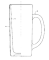
- Drawing 2 is a fracture view showing typically an example of the glass container concerning an embodiment.
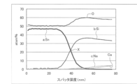
- FIG. 3 is a diagram illustrating a depth profile according to an embodiment by XPS analysis.
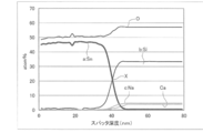
- FIG. 4 is a diagram illustrating a depth profile according to a comparative example by XPS analysis.
- FIG. 5 is a diagram showing the relationship between the flame temperature and flame treatment time of samples according to Examples and Comparative Examples.
- FIG. 6 is a diagram showing the relationship between the flame temperature and flame treatment time of a sample according to a comparative example.
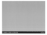
- FIG. 7 is an electron micrograph of the surface of the coating according to the example.
- FIG. 8 is an electron micrograph of the surface of the coating according to the comparative example.
- FIG. 1 is a perspective view schematically illustrating a glass container manufacturing apparatus according to an embodiment.
- Drawing 2 is a fracture view showing typically an example of the glass container concerning an embodiment.
- FIG. 3
- FIG. 9 is an image obtained by an atomic force microscope according to the example.
- FIG. 10 is an image obtained by an atomic force microscope according to the example.
- FIG. 11 is an image obtained by an atomic force microscope according to the example.
- FIG. 12 is an image obtained by an atomic force microscope according to the example.
- FIG. 13 is an image obtained by an atomic force microscope according to a comparative example.
- FIG. 14 is an image obtained by an atomic force microscope according to a comparative example.
- FIG. 15 is a diagram illustrating a method for measuring scratch strength.
- FIG. 16 is a diagram showing the relationship between the film thickness of the coating film and the scratch generation load in the scratch strength.
- FIG. 17 is a diagram showing the relationship between the temperature of the container body and the flaw generation load in the heating process in the scratch strength.
- FIG. 1 is a diagram schematically illustrating an example of a manufacturing apparatus 1000 according to the present embodiment.
- the manufacturing apparatus 1000 includes a forming apparatus 100 for forming a container body 12 made of glass, a heating apparatus 200 for heating the container body 12, and tin oxide or A film forming apparatus 300 for forming a titanium oxide film and a slow cooling apparatus 500 for gradually cooling the glass container 10 on which the film is formed are included.
- the heating device 200 and the film forming device 300 are provided along the transport device 400.
- the molding apparatus 100 includes a table 120 rotatably provided on the support unit 110 and a plurality of molds 130 disposed on the table 120. Above the table 120, a cylinder 140 capable of moving up and down and a cutter 150 for cutting molten glass are provided. The cylinder 140 can form the molten glass in the mold 130 by moving downward.
- the conveying apparatus 400 has a plurality of tables 410 on which the container body 12 and the glass container 10 can be placed. These tables 410 are arranged adjacent to each other in a loop shape, and each table 410 is provided to be rotatable in a predetermined direction. Further, the plurality of tables 410 arranged in a loop form continuously move in the direction indicated by the symbol A (counterclockwise in FIG. 1) by a driving device (not shown).
- a transfer device 160 for transferring the container body 12 from the molding device 100 to the transfer device 400 is provided between the forming device 100 and the transfer device 400.
- the transfer device 160 has a grip 162. By moving the grip 162, the container body 12 can be transferred while being held.
- the heating device 200 is disposed at a position where the container body 12 on the table 410 can be heated.
- the heating device 200 includes a plurality of burners 210 arranged along the transfer direction of the container body 12. Since the container main body 12 is rotated by the rotation of the table 410, the flame generated by the heating device 200 is uniformly applied to the outer surface of the container main body 12.
- the film forming apparatus 300 is provided adjacent to the heating apparatus 200.
- the inside of the film forming apparatus 300 is kept at a predetermined temperature, and has a raw material gas supply means (not shown).
- the source gas is supplied toward at least the outer side surface of the container body 12.
- the slow cooling device 500 has a slow cooling means by gas or electric heating (not shown).
- a first conveyor 510 and a second conveyor 520 are provided between the transport device 400 and the slow cooling device 500.
- a transfer device 430 for transferring the glass container 10 on which the film is formed from the transfer device 400 to the first conveyor 510 is provided between the transfer device 400 and the first conveyor 510.
- the transfer device 430 has a grip 432. By moving the grip 432, the glass container 10 can be transferred while being held.
- the glass container 10 disposed on the first conveyor 510 can be moved to the second conveyor 520 by the pusher 540.
- the manufacturing method of the glass container concerning this embodiment can manufacture the glass container 10 using the said manufacturing apparatus.
- the manufacturing method according to the present embodiment includes a first step of forming a container body 12 made of glass, and heat treatment in a state where the container body 12 is kept at a temperature of 580 ° C. or higher, so that sodium in the surface region of the container body 12 is obtained. And a third step of forming a film of tin oxide or titanium oxide having a film thickness of 40 nm or more and 50 nm or less on the surface of the container main body 12.
- the container body 12 is molded using the molding apparatus 100.
- the molding apparatus is not limited to the molding apparatus 100 described above, and a known glass molding machine can be used.
- the container main body 12 is transferred to the table 410 of the transfer device 400 by the transfer means 160.
- the container body 12 is transferred to the heating device 200.
- the container body 12 is subjected to heat treatment in a state where it is maintained at a temperature of 580 ° C. or higher, preferably 600 ° C. or higher and 770 ° C. or lower.
- the burner is used as the heating apparatus 200, flame treatment by oxyfuel combustion can be used.
- the flame temperature is preferably 1250 ° C. or higher and 1600 ° C.
- the contact time between the flame and the container body 12 is preferably 0.5 seconds or more and 2 seconds or less, more preferably 0.8 seconds or more and 2 seconds or less.
- the surface of the glass of the container body 12 is maintained by maintaining the temperature of the container body 12 in a predetermined range and heating the container body 12 under a predetermined condition by flame treatment.
- the concentration of sodium can be reduced by removing the sodium in the region, and as a result, a glass container excellent in alkali resistance and scratch resistance can be formed. The reason for this will be described in detail later.
- the container body 12 is transferred to the film forming apparatus 300 by the transport device 400, and a tin oxide or titanium oxide film having a film thickness of 40 nm or more and 50 nm or less is formed on the surface of the container body 12.
- These films are formed by, for example, a known hot end coating method.
- the following raw material and film formation method can be used as the method for producing the coating.
- the raw material material for the coating is not particularly limited as long as it is a material that can be thermally decomposed and / or hydrolyzed to form tin oxide or titanium oxide.
- tin tetrachloride, monobutyltin trichloride, dimethyltin dichloride and the like can be used as the tin compound
- titanium tetrachloride and the like can be used as the titanium compound.
- other metal compounds can be added within the scope of the object of the present invention.
- the method for forming the film is not particularly limited as long as the film is formed by contacting the raw material gas with the surface of the container body 12 set to a desired temperature range. Examples of the film forming method include chemical vapor deposition.
- the temperature of the source gas is preferably 130 to 150 ° C.
- the treatment time is preferably 2 to 4 seconds, although it depends on the temperature of the source gas and the film thickness.
- the source gas can be supplied according to the film formation region. For example, when it is desired to form a film on the side surface of the glass container (beer mug) shown in FIG. 2, a raw material gas is sprayed on the outer side surface of the container body 12, and a gas not containing the raw material gas is supplied to the inside of the container body 12. can do.
- FIG. 2 is a cutaway view schematically showing the glass container 10 according to the present embodiment.
- the glass container 10 is a beer mug, but the glass container 10 is not limited to this.
- the glass container 10 has a container body 12 made of glass and a coating 14 formed on the surface of the container body 12, and the coating 14 is made of tin oxide or titanium oxide,
- the film 14 has a thickness of 40 nm to 50 nm, and in the depth profile obtained by X-ray photoelectron spectroscopy (XPS) analysis, the atomic% of sodium at the point where the tin or titanium profile and the silicon profile intersect is 2%. It is as follows.
- the container body 12 is a container obtained by molding glass, and the glass is not particularly limited, such as soda lime glass.
- the coating 14 is made of tin oxide or titanium oxide, and the film thickness is 40 nm or more and 50 nm or less. When the film thickness of the coating film 14 is within this range, an iris color is not generated and the aesthetic appearance of the glass container 10 is not impaired while ensuring sufficient alkali resistance and scratch resistance.
- the coating 14 can be preferably formed on the entire surface of the container body 12 except the bottom surface, but can be formed on a part of the surface of the container body 12, particularly on at least the outer side surface of the container body 12. As described above, the coating 14 is formed on at least the outer side surface of the container body 12, so that it is possible to effectively prevent the generation of scratches due to the contact between the glass containers 10.
- the atomic% of sodium at the point where the tin or titanium profile and the silicon profile intersect is 2% or less.
- a depth profile obtained by performing XPS analysis using a sample of a glass container 10 sodium at a point X where a tin Sn profile a and a silicon Si profile b intersect.
- the atomic% (atom%) of the profile c is 2% or less, preferably 1% or less.
- FIG. 4 shows a depth profile obtained by performing the XPS analysis according to the comparative example.
- the atomic% (atom%) of the sodium profile c at the point X where the tin Sn profile a and the silicon Si profile b cross each other exceeds 2%.
- the data shown in FIGS. 3 and 4 will be described in detail later in the examples.
- the coating film 14 is dense and has high strength without the occurrence of pinholes due to the sodium salt.
- the glass container 10 according to the present invention has the following physical properties.
- the coating film 14 preferably has a surface hardness of 7000 N / mm 2 or more and 8500 N / mm 2 or less according to an ultra micro load hardness test based on JIS Z 2255: 2003.
- the coating film 14 has a surface roughness measured by an atomic force microscope (AFM) of preferably 15 nm or less. The measurement conditions for the surface roughness will be described in detail in Examples.
- AFM atomic force microscope
- the coating film 14 has a scratch strength of preferably 8 kg or more, more preferably 9 kg or more.
- the measurement conditions for the scratch strength will be described in detail in the examples.
- the scratch strength is greatly influenced by the surface hardness and surface roughness of the coating 14, and it is important that both take values in the above range.
- the container body (cylinder for beer mug) was molded by the molding apparatus 100 using soda lime glass. Next, heat treatment was performed using an oxygen flame with a heating device (burner 210) while maintaining the container body at a predetermined temperature, and sodium in the outer surface area of the container body was desorbed. Subsequently, a 40 nm-thick tin oxide film was formed on the outer surface of the container body using the film forming apparatus 300 at a source gas temperature of 130 ° C. and a film formation time of 2 seconds.
- samples of Examples 1 to 9 and Comparative Examples 1 to 10 were formed by changing the flame temperature, the flame treatment time, and the temperature of the container body.
- Table 1 shows the flame temperature, the flame treatment time, and the temperature of the sample container body, together with the results of the dishwasher resistance described later.
- 5 and 6 show the results of flame temperature, flame treatment time, and dishwasher resistance.
- Comparative Examples 11 and 12 were formed as comparative examples in which no flame treatment was performed. Specifically, in Comparative Example 11, a sample was formed in the same manner as in Example 1 except that the flame treatment was not performed and the film thickness of the film was 12.5 nm. In Comparative Example 12, a sample was formed in the same manner as in Example 1 except that the flame treatment was not performed and the film thickness was set to 80 nm. Comparative Example 12 is in accordance with the coating film manufacturing method described in JP-A-3-131547.
- Comparative Examples 1 to 12 a “bad” result was obtained and whitening was observed.
- a silver-white iris was observed. This is because, in the sample of Comparative Example 12, an iris is originally observed because the film is as thick as 80 nm. However, a pinhole is formed on the surface of the film by repeated cleaning by a dishwasher, and silver white due to irregular reflection of light on the surface. This is thought to be due to the more emphasized iris.
- the temperature of the container main body is 580 ° C. or more, the flame temperature is preferably about 1,250 ° C. to 1,600 ° C., and the flame treatment time is preferably about 0.5 seconds to 2 seconds. In the following, it was confirmed that the time was more preferably 0.8 seconds or more and 2 seconds or less. In Example 5, since the flame temperature was high, a “slightly good” result was obtained even if the flame treatment time was short.
- Example 10 a container body (a cylinder of a beer mug) was molded by a molding apparatus 100 using soda lime glass. Next, with the container body kept at 700 ° C., the heating device (burner 210) is heated using an oxygen flame at a flame temperature of 1420 ° C. and a flame treatment time of 1 second to remove sodium from the outer surface area of the container body. Released. Subsequently, a coating film of tin oxide having a film thickness of 40 nm was formed on the outer surface of the container body using the film forming apparatus 300 at a raw material gas temperature of 140 ° C. and a film forming time of 2 seconds. In this way, a sample of Example 10 was obtained.
- Example 10 A sample of Comparative Example 13 was obtained in the same manner as Example 10 except that no flame treatment was performed. In this case, the temperature of the container body at the time of film formation was 580 ° C.
- the production conditions for Example 10 and Comparative Example 13 are shown in Table 2.
- Example 10 Comparative Example 13
- Example 10 Comparative Example 13
- FIGS. The magnification of the micrograph was 5000 times.
- Example 10 Surface hardness of the coating
- Example 11 a sample was prepared in the same manner as in Example 10 except that the film thickness of 40 nm in Example 10 was changed to 48 nm.
- Comparative Examples 11 and 12 and Comparative Example 14 were used.
- Comparative Example 14 a sample was prepared in the same manner as in Example 10 except that the film thickness of 40 nm in Example 10 was changed to 64 nm.
- Apparatus Elionix Co., Ltd. ultra-fine indentation hardness tester ENT-1100a Test condition: Test load 0.1mN Pushing condition 500step / step interval 20msec Test temperature 25 °C ⁇ 1 °C (3) Measurement results Table 3 shows the measurement results.
- the surface hardness of this example is preferably approximately 7000 N / mm 2 or more and 8500 N / mm 2 or less.
- Example 9 and 12 Surface roughness of coating
- Example 12 a sample was prepared by setting the flame temperature in the flame treatment to 1420 ° C., the flame treatment time to 2 seconds, and the temperature of the container body in the flame treatment to 720 ° C. For comparison, the sample of Comparative Example 12 was used. Table 4 shows the production conditions for the samples of Example 12 and Comparative Example 12.
- the surface roughness of the coating was measured with an atomic force microscope (AFM) under the following conditions. In the measurement, a sample piece of about 10 mm square was created by cutting out from approximately the center of the sample glass container. The surface roughness was measured by scanning the surface of the sample piece for irregularities on an area of 1 ⁇ m or 10 ⁇ m on any side.
- Apparatus Digital Instruments Corporation Nanoscope (stylus type AFM) Test condition: Scan rate 1.001 Hz Scan size 1 ⁇ m or 10 ⁇ m
- Example 12 (3) Measurement Results
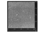
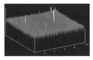
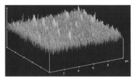
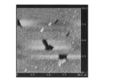
- the results of Example 12 are shown in FIGS. 9 and 10, the results of Example 9 are shown in FIGS. 11 and 12, and the results of Comparative Example 12 are shown in FIGS. From these results, the sample of Example 12 had a surface roughness (Rms) of 13.68 nm, and the sample of Example 9 had a surface roughness (Rms) of 14.34 nm. From this, it was confirmed that the higher the temperature of the container body during the heat treatment, the smaller the surface roughness and the smaller the crystals of the film.
- sample A is placed on a weighing machine (automatic balance) and the weight is reset to zero.
- sample B is brought into contact with sample A, and as indicated by arrow Z, while maintaining a state of being pressed with an arbitrary load from above, as shown by arrow X, from the body part of sample A toward the mouth part Rub sample B. If no scratch was generated, the same test was repeated while increasing the load to be pressed by 1 kg, and the load at which the surface of sample A was scratched was determined.
- FIGS. 16 and 17 show the measurement results.
- FIG. 16 shows the relationship between the film thickness of the coating film and the scratch generation load
- FIG. 17 shows the relationship between the temperature of the container body and the scratch generation load in the heat treatment.
- the symbol indicated by “e” is the result of the example
- the symbol indicated by “c” is the result of the comparative example.
- the alkali resistance by removing or reducing sodium in the surface region of the container body, the alkali resistance, the smoothness of the coating surface, the surface hardness, the surface roughness, and the scratch are obtained. Very good results were obtained in strength. As a result, according to the glass container of the present invention, it is excellent in scratch resistance, alkali resistance, dishwasher resistance, etc., and is excellent in aesthetic appearance without generation of iris.
- the present invention is not limited to the embodiment described above, and various modifications are possible.
- the present invention includes substantially the same configuration (for example, a configuration having the same function, method, and result, or a configuration having the same purpose and effect) as the configuration described in the embodiment.
- the invention includes a configuration in which a non-essential part of the configuration described in the embodiment is replaced.
- the present invention includes a configuration that achieves the same effect as the configuration described in the embodiment or a configuration that can achieve the same object.
- the invention includes a configuration in which a known technique is added to the configuration described in the embodiment.
Landscapes
- Chemical & Material Sciences (AREA)
- Engineering & Computer Science (AREA)
- Materials Engineering (AREA)
- Organic Chemistry (AREA)
- General Chemical & Material Sciences (AREA)
- Life Sciences & Earth Sciences (AREA)
- Chemical Kinetics & Catalysis (AREA)
- Geochemistry & Mineralogy (AREA)
- Mechanical Engineering (AREA)
- Thermal Sciences (AREA)
- Physics & Mathematics (AREA)
- Ceramic Engineering (AREA)
- Details Of Rigid Or Semi-Rigid Containers (AREA)
- Surface Treatment Of Glass (AREA)
- Table Devices Or Equipment (AREA)
Abstract
Priority Applications (6)
| Application Number | Priority Date | Filing Date | Title |
|---|---|---|---|
| US16/096,170 US20190135685A1 (en) | 2016-05-12 | 2017-04-18 | Glass container, and method and apparatus for manufacturing the same |
| DE112017002437.4T DE112017002437B4 (de) | 2016-05-12 | 2017-04-18 | Glasbehälter und Verfahren und Vorrichtung zur Herstellung desselben |
| CN201780029036.4A CN109153600B (zh) | 2016-05-12 | 2017-04-18 | 玻璃容器及其制造方法 |
| JP2017545977A JP6248234B1 (ja) | 2016-05-12 | 2017-04-18 | ガラス容器およびその製造方法 |
| KR1020187035344A KR102158575B1 (ko) | 2016-05-12 | 2017-04-18 | 유리용기 및 그 제조방법 |
| US17/117,596 US20210094869A1 (en) | 2016-05-12 | 2020-12-10 | Glass Container, And Method And Apparatus For Manufacturing The Same |
Applications Claiming Priority (2)
| Application Number | Priority Date | Filing Date | Title |
|---|---|---|---|
| JP2016096192 | 2016-05-12 | ||
| JP2016-096192 | 2016-05-12 |
Related Child Applications (2)
| Application Number | Title | Priority Date | Filing Date |
|---|---|---|---|
| US16/096,170 A-371-Of-International US20190135685A1 (en) | 2016-05-12 | 2017-04-18 | Glass container, and method and apparatus for manufacturing the same |
| US17/117,596 Division US20210094869A1 (en) | 2016-05-12 | 2020-12-10 | Glass Container, And Method And Apparatus For Manufacturing The Same |
Publications (1)
| Publication Number | Publication Date |
|---|---|
| WO2017195539A1 true WO2017195539A1 (fr) | 2017-11-16 |
Family
ID=60266955
Family Applications (1)
| Application Number | Title | Priority Date | Filing Date |
|---|---|---|---|
| PCT/JP2017/015566 Ceased WO2017195539A1 (fr) | 2016-05-12 | 2017-04-18 | Récipient en verre, procédé et dispositif pour sa fabrication |
Country Status (7)
| Country | Link |
|---|---|
| US (2) | US20190135685A1 (fr) |
| JP (1) | JP6248234B1 (fr) |
| KR (1) | KR102158575B1 (fr) |
| CN (1) | CN109153600B (fr) |
| DE (1) | DE112017002437B4 (fr) |
| TW (1) | TWI729131B (fr) |
| WO (1) | WO2017195539A1 (fr) |
Families Citing this family (3)
| Publication number | Priority date | Publication date | Assignee | Title |
|---|---|---|---|---|
| HUE052933T2 (hu) * | 2015-04-24 | 2021-05-28 | Nipro Corp | Eljárás gyógyszeres üvegedény elõállítására, valamint egy rotátorral ellátott tûzfúvó eszköz |
| CN114040898B (zh) * | 2019-05-17 | 2024-08-23 | 康宁公司 | 具有铜膜的玻璃片及其制作方法 |
| JP7423914B2 (ja) * | 2019-06-14 | 2024-01-30 | ニプロ株式会社 | 皮膜付きガラスおよびその製造方法並びに改質されたガラス基材 |
Citations (7)
| Publication number | Priority date | Publication date | Assignee | Title |
|---|---|---|---|---|
| JPS5028517A (fr) * | 1973-06-25 | 1975-03-24 | ||
| JPH03131547A (ja) * | 1989-07-26 | 1991-06-05 | Kirin Brewery Co Ltd | ガラス壜とその製造法 |
| JPH08133786A (ja) * | 1994-11-10 | 1996-05-28 | Asahi Breweries Ltd | ガラス食器 |
| JPH11116249A (ja) * | 1997-10-08 | 1999-04-27 | Kirin Brewery Co Ltd | 壜の製造方法およびその装置 |
| JP2000302483A (ja) * | 1999-04-23 | 2000-10-31 | Toyo Glass Co Ltd | ガラスびんの外面処理方法及びガラスびん |
| JP2005170736A (ja) * | 2003-12-11 | 2005-06-30 | Ishizuka Glass Co Ltd | 酸化反応抑制ガラス材及び酸化反応抑制ガラス容器 |
| JP2008074477A (ja) * | 2006-09-25 | 2008-04-03 | Ishizuka Glass Co Ltd | 着色ガラス製品の製造方法とそのコーティング液及び着色ガラス製品 |
Family Cites Families (7)
| Publication number | Priority date | Publication date | Assignee | Title |
|---|---|---|---|---|
| CO4560356A1 (es) * | 1995-02-22 | 1998-02-10 | Elf Atochem Vlissingen Bv | Proceso para la produccion de un recubrimiento de proteccion sobre la superficie de un articulo de vidrio o ceramica |
| EP0905096B1 (fr) * | 1997-09-24 | 2004-06-09 | Kirin Beer Kabushiki Kaisha | Procédé et appareil pour fabriquer et revêtir des bouteilles |
| JP2001146438A (ja) | 1999-11-16 | 2001-05-29 | Asahi Breweries Ltd | ガラスびんの外面処理方法及びガラスびん |
| US7623704B2 (en) * | 2003-01-31 | 2009-11-24 | Fuji Xerox Co. Ltd. | Color processing method, color processing apparatus, and storage medium |
| CA2522807A1 (fr) * | 2003-04-22 | 2004-11-04 | The Coca-Cola Company | Procede et appareil de renforcement du verre |
| EP2546205B1 (fr) * | 2005-05-16 | 2016-01-13 | Nipro Corporation | procédé de production pour fioles |
| US9162780B2 (en) * | 2013-10-03 | 2015-10-20 | Owens-Brockway Glass Container Inc. | Preparing a sealing surface of a container |
-
2017
- 2017-04-18 DE DE112017002437.4T patent/DE112017002437B4/de active Active
- 2017-04-18 JP JP2017545977A patent/JP6248234B1/ja active Active
- 2017-04-18 WO PCT/JP2017/015566 patent/WO2017195539A1/fr not_active Ceased
- 2017-04-18 CN CN201780029036.4A patent/CN109153600B/zh active Active
- 2017-04-18 KR KR1020187035344A patent/KR102158575B1/ko active Active
- 2017-04-18 US US16/096,170 patent/US20190135685A1/en not_active Abandoned
- 2017-05-12 TW TW106115846A patent/TWI729131B/zh active
-
2020
- 2020-12-10 US US17/117,596 patent/US20210094869A1/en not_active Abandoned
Patent Citations (7)
| Publication number | Priority date | Publication date | Assignee | Title |
|---|---|---|---|---|
| JPS5028517A (fr) * | 1973-06-25 | 1975-03-24 | ||
| JPH03131547A (ja) * | 1989-07-26 | 1991-06-05 | Kirin Brewery Co Ltd | ガラス壜とその製造法 |
| JPH08133786A (ja) * | 1994-11-10 | 1996-05-28 | Asahi Breweries Ltd | ガラス食器 |
| JPH11116249A (ja) * | 1997-10-08 | 1999-04-27 | Kirin Brewery Co Ltd | 壜の製造方法およびその装置 |
| JP2000302483A (ja) * | 1999-04-23 | 2000-10-31 | Toyo Glass Co Ltd | ガラスびんの外面処理方法及びガラスびん |
| JP2005170736A (ja) * | 2003-12-11 | 2005-06-30 | Ishizuka Glass Co Ltd | 酸化反応抑制ガラス材及び酸化反応抑制ガラス容器 |
| JP2008074477A (ja) * | 2006-09-25 | 2008-04-03 | Ishizuka Glass Co Ltd | 着色ガラス製品の製造方法とそのコーティング液及び着色ガラス製品 |
Also Published As
| Publication number | Publication date |
|---|---|
| TW201806898A (zh) | 2018-03-01 |
| TWI729131B (zh) | 2021-06-01 |
| CN109153600A (zh) | 2019-01-04 |
| DE112017002437T5 (de) | 2019-04-25 |
| JP6248234B1 (ja) | 2017-12-13 |
| KR20190006181A (ko) | 2019-01-17 |
| KR102158575B1 (ko) | 2020-09-23 |
| US20210094869A1 (en) | 2021-04-01 |
| CN109153600B (zh) | 2022-04-19 |
| US20190135685A1 (en) | 2019-05-09 |
| DE112017002437T8 (de) | 2019-09-05 |
| DE112017002437B4 (de) | 2025-01-30 |
| JPWO2017195539A1 (ja) | 2018-05-24 |
Similar Documents
| Publication | Publication Date | Title |
|---|---|---|
| JP6376607B2 (ja) | 反射低減ガラス物品ならびにその製造方法および使用方法 | |
| JP2022033904A (ja) | 高強度の超薄ガラスおよびその製造方法 | |
| TW201934515A (zh) | 具抗刮擦性的紋理化基於玻璃之製品及其製作方法 | |
| CN105164075B (zh) | 用于光学质量玻璃成形的高纯度镍模具和采用所述模具成形玻璃片的方法 | |
| JP6395723B2 (ja) | ガラス板の製造方法及びガラス板 | |
| JP6248234B1 (ja) | ガラス容器およびその製造方法 | |
| TW201245075A (en) | Glass with high frictive damage resistance | |
| TWI707833B (zh) | 顯示器用玻璃基板、及顯示器用玻璃基板之製造方法 | |
| CN107848875A (zh) | 用于化学强化的玻璃基板和用受控曲率进行化学强化的方法 | |
| TW201710064A (zh) | 積層體 | |
| CN102459107A (zh) | 玻璃处理方法 | |
| US20130338051A1 (en) | Method for producing chemically strengthened glass substrate for display device | |
| TW202330432A (zh) | 化學強化玻璃之製造方法、化學強化玻璃、覆蓋玻璃及顯示裝置 | |
| TW200811075A (en) | Anti-dazzling glass and method for producing anti-dazzling glass | |
| JP7024373B2 (ja) | ディスプレイ用ガラス基板 | |
| WO2018043253A1 (fr) | Procédé de production de verre en plaque antireflet | |
| JPWO2015194569A1 (ja) | ガラス板及びその製造方法 |
Legal Events
| Date | Code | Title | Description |
|---|---|---|---|
| ENP | Entry into the national phase |
Ref document number: 2017545977 Country of ref document: JP Kind code of ref document: A |
|
| 121 | Ep: the epo has been informed by wipo that ep was designated in this application |
Ref document number: 17795900 Country of ref document: EP Kind code of ref document: A1 |
|
| ENP | Entry into the national phase |
Ref document number: 20187035344 Country of ref document: KR Kind code of ref document: A |
|
| 122 | Ep: pct application non-entry in european phase |
Ref document number: 17795900 Country of ref document: EP Kind code of ref document: A1 |