WO2017195573A1 - 光学特性測定装置 - Google Patents
光学特性測定装置 Download PDFInfo
- Publication number
- WO2017195573A1 WO2017195573A1 PCT/JP2017/016063 JP2017016063W WO2017195573A1 WO 2017195573 A1 WO2017195573 A1 WO 2017195573A1 JP 2017016063 W JP2017016063 W JP 2017016063W WO 2017195573 A1 WO2017195573 A1 WO 2017195573A1
- Authority
- WO
- WIPO (PCT)
- Prior art keywords
- measurement
- opening
- gloss
- optical property
- measuring apparatus
- Prior art date
- Legal status (The legal status is an assumption and is not a legal conclusion. Google has not performed a legal analysis and makes no representation as to the accuracy of the status listed.)
- Ceased
Links
Images


Classifications
-
- G—PHYSICS
- G01—MEASURING; TESTING
- G01J—MEASUREMENT OF INTENSITY, VELOCITY, SPECTRAL CONTENT, POLARISATION, PHASE OR PULSE CHARACTERISTICS OF INFRARED, VISIBLE OR ULTRAVIOLET LIGHT; COLORIMETRY; RADIATION PYROMETRY
- G01J3/00—Spectrometry; Spectrophotometry; Monochromators; Measuring colours
- G01J3/46—Measurement of colour; Colour measuring devices, e.g. colorimeters
- G01J3/50—Measurement of colour; Colour measuring devices, e.g. colorimeters using electric radiation detectors
-
- G—PHYSICS
- G01—MEASURING; TESTING
- G01N—INVESTIGATING OR ANALYSING MATERIALS BY DETERMINING THEIR CHEMICAL OR PHYSICAL PROPERTIES
- G01N21/00—Investigating or analysing materials by the use of optical means, i.e. using sub-millimetre waves, infrared, visible or ultraviolet light
- G01N21/17—Systems in which incident light is modified in accordance with the properties of the material investigated
- G01N21/55—Specular reflectivity
- G01N21/57—Measuring gloss
Definitions
- the present invention relates to an optical characteristic measuring apparatus that measures predetermined optical characteristics such as color and gloss.
- Patent Document 1 discloses an optical characteristic measurement device that receives reflected light reflected from a measurement object and measures surface characteristics of the measurement object.
- the optical measuring instrument disclosed in Patent Document 1 includes a light source, a mirror that further reflects the measurement light emitted from the light source and reflected by the measurement target, and the optical path of the measurement light reflected by the mirror.
- a condensing lens that collects the measurement light that is arranged along the mirror and reflected by the mirror, and a light receiving signal corresponding to the measurement light that has a light receiving surface on the rear focal plane of the condensing lens and is received by the light receiving surface
- a finder disposed at a position sandwiching the mirror with respect to the measurement position, and the mirror is disposed so as to be movable so as to be adjustable in inclination, and from the finder to the mirror The measurement position of the measurement object can be confirmed via the.
- Patent Document 1 when the mirror moves, the position and tilt of the mirror may shift, and it may be difficult to clearly and accurately see the measurement position of the measurement target, resulting in a decrease in measurement reproducibility. As a result, the performance may be reduced.
- An object of the present invention is to provide an optical characteristic measuring apparatus that can directly check the measurement position of a measurement object without using a mirror.
- An optical property measurement apparatus includes an optical property measurement unit that has a measurement aperture and measures a plurality of different optical properties in a measurement object facing the measurement aperture by using a plurality of optical systems having different geometries. And a measurement object observation unit that directly observes the measurement object that faces the measurement opening, and an observation light source that illuminates the measurement object that faces the measurement opening. Therefore, the optical property measurement apparatus according to the present invention can directly confirm the measurement position of the measurement object without using a mirror.
- FIG. 1 It is the perspective view which looked at the optical characteristic measuring device in an embodiment from the right front side. It is the perspective view which looked at the optical characteristic measuring apparatus shown in FIG. 1 from the left front side. It is a side view of the optical characteristic measuring apparatus shown in FIG. It is a bottom view of the optical characteristic measuring apparatus shown in FIG. It is sectional drawing of the optical characteristic measurement part which the optical characteristic measuring apparatus shown in FIG. 1 has. It is a schematic diagram of a structure of the optical characteristic measurement part which the optical characteristic measuring apparatus shown in FIG. 1 has. It is explanatory drawing for demonstrating the positional relationship of the through-opening with respect to the measurement opening which the optical characteristic measuring apparatus shown in FIG. 1 has. It is a perspective view of the shutter mechanism which the optical characteristic measuring apparatus shown in FIG. 1 has.
- FIG. 10 is a perspective view of a state in which the shutter mechanism of the modification shown in FIG. 9 is attached to the housing. It is a schematic diagram of the structure which has arrange
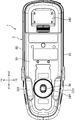
- FIG. 1 is a perspective view of an optical characteristic measuring apparatus according to an embodiment as viewed from the right front side.
- FIG. 2 is a perspective view of the optical characteristic measuring apparatus shown in FIG. 1 as viewed from the left front side.
- FIG. 3 is a side view of the optical property measuring apparatus shown in FIG.
- FIG. 4 is a bottom view of the optical characteristic measuring apparatus shown in FIG.
- X1 is the forward direction
- X2 is the backward direction
- Y1 direction is the right direction
- Y2 direction is the right direction.
- FIG. 5 is a cross-sectional view of an optical property measuring unit included in the optical property measuring apparatus shown in FIG.
- FIG. 6 is a schematic diagram of a configuration of an optical property measuring unit included in the optical property measuring apparatus shown in FIG.
- FIG. 7 is an explanatory diagram for explaining the positional relationship of the through-opening with respect to the measurement opening included in the optical characteristic measuring apparatus shown in FIG.
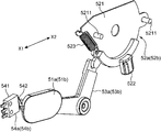
- FIG. 8 is a perspective view of a shutter mechanism included
- the optical property measuring apparatus 1 in the present embodiment includes a housing 2, an optical property measuring unit 3 (shown in FIG. 5) accommodated in the housing 2, a through-opening (measurement target observation unit) 4a formed in the housing 2. 4b.
- the optical property measurement unit 3 is configured to measure a plurality of different optical properties in the measurement object 100 facing the measurement openings 4a and 4b by using a plurality of optical systems having different geometries.
- the optical property measurement unit 3 includes a measurement aperture 30, a gloss measurement unit 31 that measures the gloss of the measurement object 100 disposed in the measurement aperture 30, and a measurement aperture.
- the color measurement unit 32 that measures the color (object color, light source color) of the measurement object 100 arranged at 30, and the gloss value and the color value are obtained based on the measurement data obtained by the gloss measurement unit 31 and the color measurement unit 32.
- a control unit 33 and a monitor (display unit) 34 that displays gloss values, color values, and the like obtained by the control unit 33 are provided.
- the gloss measurement unit 31 includes, for example, a gloss measurement light source 311, and an irradiation diameter switching unit 312 that appropriately switches the irradiation diameter of the light of the gloss measurement light source 311 that hits the measurement target 100 according to the size of the measurement site of the measurement target 100.
- the gloss measurement unit 31 configured in this manner applies light from the gloss measurement light source 311 to the measurement site of the measurement object 100 facing the measurement opening 30 via the irradiation diameter switching unit 312 and the gloss measurement illumination lens 313, Further, the light reflected by the measurement object 100 is received by the gloss detector 315 via the gloss measurement light receiving lens 314 to detect gloss data related to gloss. Based on the gloss data relating to the detected gloss, the control unit 33 obtains the gloss value by a known method, and the obtained gloss value is displayed on the monitor 34.
- the irradiation diameter switching unit 312 has, for example, a light shielding property in which a plurality of through holes having different diameters (for example, a first through hole having a first diameter and a second through hole having a second diameter smaller than the first diameter) are formed.
- the illumination light from the gloss measurement light source 311 passes through the first through-hole, and the irradiation diameter becomes the first diameter, and the illumination light from the gloss measurement light source 311 passes through the second through-hole.
- it is configured to be movable in a direction orthogonal to the optical path so that the irradiation diameter is the second diameter.
- the color measurement unit 32 includes a color measurement measurement light source 321, an irradiation light reflection mirror 322, a reflection light mirror 323, a measurement light receiving diameter switching lens 324, a spectroscopic unit 326, and the like. It is configured to be geometry.
- the colorimetric unit 32 configured in this manner applies light from the colorimetric measurement light source 321 to the measurement site of the measurement target 100 facing the measurement aperture 30 via the irradiation light reflection mirror 322, and further, the measurement target 100
- the reflected light is received by the spectroscopic unit 326 via the reflected light mirror 323 and the measurement light-receiving diameter switching lens 324, and colorimetric data relating to colorimetry is detected.
- the control unit 33 obtains a color value by a known method, and the obtained color value is displayed on the monitor 34.
- the gloss geometry in the gloss measurement unit 31 and the color measurement geometry in the color measurement unit 32 are different from each other.
- the gloss geometry is 60 °: 60 °, that is, the measurement object 100 is illuminated at 60 degrees with respect to the sample normal, and the reflected light is received in the specular reflection direction, while the color measurement geometry. Illuminates the measurement object 100 at 45 degrees with respect to the sample normal, and receives reflected light in the 0 degree direction. These may be other geometries.
- the housing 2 includes an upper wall 21, a pair of right side walls (first side walls) 22 and left side walls (second side walls) 23, a bottom wall 24, and a rear wall 25. And.
- the upper wall 21 holds the monitor 34 of the optical characteristic measuring unit 3 described above, and the measured value measured by the optical characteristic measuring unit 3, for example, is displayed on the monitor 34.
- the bottom wall 24 has a circular first contact portion 241 and a substantially rectangular second contact portion 242 that are in contact with the measurement target 100 when measuring the measurement target 100 on the front side and the rear side, respectively. And.
- the measurement opening 30 described above is formed in a circular shape at the center of the first contact portion 241.
- the first through opening 4a is formed in the right side wall 22.
- the first through opening 4a is for directly observing the measurement object 100 facing the measurement opening 30 and is formed so as to penetrate from the outer surface of the right side wall 22 to the inner surface.
- a translucent member 221 such as a transparent resin or transparent glass that transmits visible light is fitted into the first through opening 4a.
- the right side wall 22 holds shutter mechanisms 51a to 54a for opening and closing the first through opening 4a.
- the shutter mechanism of this embodiment includes a first shutter member 51a that opens and closes the first through opening 4a, a first opening and closing operation member 52a that opens and closes the first shutter member 51a, A first connecting member 53a that connects the first shutter member 51a and the first opening / closing operation member 52a, and a first opening / closing sensor 54a are provided.
- the first shutter member 51a is composed of a plate-like body having a size capable of closing the entire first through opening 4a.
- the first connecting member 53a has a substantially L shape (substantially rectangular shape) having a bent portion at an intermediate portion, one end is fixedly connected to the first shutter member 51a, and the other end is a first opening / closing operation.
- the member 52a is rotatably connected. As for this 1st connection member 53, the bending part is hold
- the first opening / closing operation member 52 a includes an operation main body 521 having two rotation restricting shafts 5211, an operation protrusion 522 for manually operating the operation main body 521, and a biasing member that urges the operation main body 521.
- the coil spring 523 is provided.
- the operation protrusion 522 is formed so as to protrude integrally from the operation main body 521, and is disposed outside the right side wall 22 so that it can be operated from the outside of the housing 2.
- the operation main body 521 is rotatably attached to the right side wall 22.
- the operation main body 521 is indicated by a one-dot chain line in FIG. 3 in which the first through opening 4a is opened from the closed position shown in FIG. 3 in which the first shutter member 51a blocks the entire first through opening 4a by the rotation restricting shaft 5211. The range up to the open position is rotated.
- the coil spring 523 urges the rotation operation main body 521 rotated from the closed position toward the open position toward the closed position.
- the first open / close sensor 54a is for detecting whether or not the shutter member 51 is blocking the first through opening 4a.
- the first open / close sensor 54a protrudes from the sensor main body 541 and the sensor main body 541. And a detection piece 542.
- the detection piece 542 comes into contact with the rotation operation main body 521 at the closed position, and the rotation operation main body 521 rotates from the closed position toward the open position.
- the detection piece 542 is held on the right side wall 22 so as to be separated from the rotation operation main body 521.
- the first open / close sensor 54 a detects whether or not the shutter member 51 is blocking the first through opening 4 a and outputs the detection result to the control unit 33.
- the control unit 33 displays the detection result of the first opening / closing sensor 54 a on the monitor 34.
- the control unit 33 may forcibly stop the measurement of the optical characteristics when the detection result of the first opening / closing sensor 54a is out of the closed position where the shutter member 51 closes the first through opening 4a.
- the lower end of the right side wall 22 and the right side of the first contact part 241 are provided with a recess 221 in which a part of the right side wall 22 is recessed inward.
- the position of the first contact portion 241 (measurement opening 30) can be seen from the concave portion 221 even from the upper right side of the right side wall 22, for example.
- the left side wall 23 has substantially the same configuration as the right side wall 22 and is arranged symmetrically with the right side wall 22. Specifically, the left side wall 23 is formed with a second through-opening 4b having the same configuration as the first through-hole 4a and fitted with a translucent member 221.
- the left side wall 23 holds second shutter mechanisms 51b to 54b for opening and closing the second through opening 4b.
- the second shutter mechanisms 51b to 54b have the same configuration as the first shutter mechanisms 51a to 54a, and the second shutter member 51b, the second opening / closing operation member 52b, the second connecting member 53b, and the second opening / closing sensor. 54b (see FIG. 8).
- a concave portion 221 in which a part of the left and right side walls 23 is recessed inward is provided. The position of the first contact portion 241 (measurement opening 30) can be seen even from the upper left side of the left side wall 22.
- the back wall 25 has an opening portion opened in the back portion of the box formed by connecting the upper wall 21, the bottom wall 24, the right side wall (first side wall) 22 and the left side wall (second side wall) 23. It is a member that closes.
- the measurement opening 30 is provided in the desired measurement region of the measurement object 100.
- the first contact portion 241 and the second contact portion 242 are in contact with the measurement object 100 so as to match.
- the measurement opening 30 is formed on the bottom wall 24 of the optical property measuring apparatus 1 and thus cannot be seen from the outside.
- the rough position of the measurement opening 30 is found by using the concave portion 221 as a mark, and the measurement object is measured. Alignment can be made so that 100 desired measurement sites face the measurement opening 30.
- the gloss measurement light source 311 is turned on, and one of the first operation protrusion 522a and the second operation protrusion 522b is selected and operated.
- the selection of the first operation protrusion 522a and the second operation protrusion 522b may be performed by selecting the one that is easy for the operator to operate. For example, when the operator is right-handed, the first right-hand side that is easy to operate is selected.
- the operation protrusion 522a may be selected and operated, and can be easily opened. Both the first and second operation protrusions 522a and 522b may be operated.
- the first shutter member 51a or the second shutter member 51b is moved, and the first through-opening 4a or the second through-opening 4b is opened. Then, it is directly confirmed whether or not the light of the gloss measurement light source 311 hits the measurement site of the measurement object 100 facing the measurement opening 30 from the opened first through opening 4a or second through opening 4b. it can.
- the color measurement unit 32 when the measurement light from the colorimetric measurement light source 321 is incident on the measurement object 100, the color measurement unit 32, when the measurement object 100 is diffusely transmissive such as paper or plastic, A part of the light is diffused and emitted as internally reflected light.
- the radiation range extends around the illumination area, so that a so-called edge loss error occurs in which the amount of reflected light in the reflection area decreases. Therefore, in the color measurement unit 32, the irradiation diameter and the measurement diameter of the measurement site are different. Therefore, when the colorimetric measurement light source 321 is used as an observation light source, it is difficult to confirm the measurement site because the irradiation diameter and the measurement diameter of the measurement site are different.
- the gloss measurement unit 31 measures the specular reflection light reflected from the measurement target 100 by the light from the gloss measurement light source 311, and therefore the irradiation diameter hitting the measurement target 100 and the measurement diameter of the measurement site of the measurement target 100. Match. Therefore, as in the present embodiment, by using the colorimetric measurement light source 321 as an observation light source, the irradiated part that hits the measurement object 100 may be aligned with the measurement part of the measurement object 100, and the measurement object 100. The measurement position can be accurately aligned.
- the hand is released from the first operation protrusion 522a or the second operation protrusion 522b being pressed.
- the operation main body 521 rotates in the direction opposite to the above by the urging force of the coil spring 523, and the first shutter member 51a or the second shutter member 51b is moved to move the first through opening 4a or the second through opening. 4b closes.
- the optical property measuring apparatus 1 can measure the gloss of the measurement object 100 by the gloss measuring unit 31.
- the optical property measuring apparatus 1 can measure the color of the measuring object 100 by the color measuring unit 32.
- the optical property measurement apparatus 1 in the embodiment can directly observe the measurement object 100 facing the measurement opening 30 by the through openings 4a and 4b which are measurement object observation units formed in the housing 2. At the time of opening, the measurement position of the measurement object 100 can always be confirmed accurately. Since the optical characteristic measuring apparatus 1 in the embodiment can be confirmed without using a lens like a conventional product, it can be easily manufactured and can be manufactured at low cost.
- the measurement target observation unit since the measurement target observation unit is configured by the through openings 4a and 4b formed in the housing 2, the measurement target observation unit can be configured simply and manufactured at a lower cost. it can.
- the optical property measuring apparatus 1 in the embodiment further includes shutter mechanisms 51a to 54a and 51b to 54b for opening and closing the through openings 4a and 4b in the measurement object observation unit. Therefore, when confirming the measurement position of the measurement object 100, the through opening The measurement position of the measuring object 100 can be confirmed by opening 4a and 4b.
- shutter mechanisms 51a to 54a and 51b to 54b for opening and closing the through openings 4a and 4b in the measurement object observation unit. Therefore, when confirming the measurement position of the measurement object 100, the through opening The measurement position of the measuring object 100 can be confirmed by opening 4a and 4b.
- the optical characteristics of the measuring object 100 by closing the through openings 4a and 4b, it is possible to prevent light from entering the housing 2 from the outside, and external light may affect the measurement of the optical characteristics. The optical characteristics can be measured more accurately.
- the shutter mechanisms 51a to 54a and 51b to 54b can be opened and closed by manually operating the opening and closing operation members 52a and 52b, and the shutter members 51a and 51b can be easily opened and closed. Can be a thing.
- the color measurement unit 32 changes the light receiving area by changing the position of the measurement light receiving diameter switching lens 324 of the light receiving optical system without changing the irradiation diameter of the color measurement measuring light source 321 that hits the measurement target 100. Therefore, if the colorimetric measurement light source 321 is an observation light source, it is difficult to align the measurement position when measuring with a small diameter measurement site.
- the gloss measurement unit 31 includes an irradiation diameter switching unit 312 that switches the irradiation diameter of the gloss measurement light source corresponding to the measurement target, and the light receiving area is changed by changing the irradiation diameter.
- the gloss measurement light source 311 when used as an observation light source as in this embodiment, for example, when measuring the measurement site with a small diameter, such as when the measurement target 100 is a printed matter or a small part, First, the measurement part is roughly aligned with the irradiation diameter in a state larger than the diameter of the irradiation diameter measurement part, and then the irradiation part is set to the same diameter as the measurement part by the irradiation diameter switching unit 312 and the measurement part is finely positioned. To be combined. Thereby, the irradiation site
- first shutter member 51a and the second shutter member 51b are separately moved independently by the first opening / closing member 52a and the second opening / closing member 52b. Not limited, but can be changed as appropriate.
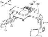
- FIG. 9 is a perspective view of a modified example of the shutter mechanism.
- FIG. 10 is a perspective view of a state in which the shutter mechanism of the modification shown in FIG. 9 is attached to the housing.
- the shutter mechanism is configured so that the first shutter member 51a and the second shutter member 51b are interlocked so that the through openings 4a and 4b can be simultaneously opened and closed by the operation of one opening and closing operation member 152. May be.
- the shutter mechanism includes two first shutter members 51a and second shutter members 51b, and a first connecting member 53a connected to the first shutter member 51a and a second connecting member 53b connected to the second shutter member 51b. And one opening / closing operation member 152.
- the opening / closing operation member 152 includes an opening / closing operation member main body 1521 and an operation projection piece 1522 formed integrally with the opening / closing operation member main body 1521 so as to protrude upward from the upper surface of the opening / closing operation member main body 1521. .
- a first connecting member 53a is rotatably connected to one end (right end) of the opening / closing operation member main body 1521, and a second connecting member 53b is rotatably connected to the other end (left end) of the opening / closing operation member 152. Yes.
- the opening / closing operation member main body 1521 is held on the upper wall 21 of the housing 2 so as to be movable in the front-rear direction (X1-X2 direction).
- the operation protrusion 1522 is received by the operation member receiving hole 211 formed in the upper wall 21 of the housing 2 so as to be movable in the front-rear direction. Yes.
- both the first connecting member 53a and the second connecting member 53b rotate in the same direction.
- the first shutter member 51a and the second shutter member 51b are interlocked to open and close the through openings 4a and 4b at the same time.
- a measurement object observation part was made into the through-opening formed in the housing 2, it is not restricted to the thing of this form,
- a measurement object observation part may be comprised from the camera which images. Good.
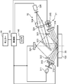
- FIG. 11 is a schematic diagram of a configuration in which a camera, which is a modified example of the measurement target observation unit included in the optical characteristic measurement apparatus, is arranged. More specifically, the right side wall (first side wall) corresponding to the position of the through-opening 4a at a position where the measurement object 100 facing the measurement opening 30 can be imaged, for example, the optical axis of the camera passes through the center position of the measurement opening 30. ) A camera is disposed at at least one of the position on the inner surface side of the left side wall (second side wall) 23 corresponding to the position of the inner surface side 22 and the position of the through opening 4b. As shown in FIG. 11, the camera 140 is electrically connected to the monitor 34 via the control unit 33 and the control unit 33 so that the measurement target 100 captured by the camera 140 can be displayed on the monitor 34. .
- the measurement object 100 facing the measurement openings 4a and 4b can be directly and easily observed on the monitor 34 via the camera 140, and the measurement position of the measurement object 100 can always be accurately confirmed.
- the through openings 4a and 4b are preferably arranged at positions where they do not overlap with the optical path from the gloss measurement light source 311 and the color measurement measurement light source 321 and the optical path extension line.
- the positions of the through openings 4a and 4b are preferably on the side of the gloss measurement light receiving lens 314, which is behind the normal line P passing through the measurement opening 30 with respect to the measurement opening 30, and more preferably 7, it is on the normal P passing through the measurement aperture 30.
- the two through openings 4a and 4b are provided.
- the through holes 4a and 4b may be formed of one through opening formed on either the right side wall 22 or the left side wall 23.
- the through openings 4a and 4b are not limited to those formed on the side walls, but may be formed on the upper wall, for example, and can be changed as appropriate.
- the observation light source is the gloss measurement light source 311.
- the observation light source is not limited to this, and for example, the color measurement measurement light source 321 is used as the observation light source, or the observation light source is The gloss measurement light source 311 and the color measurement measurement light source 321 may be provided separately and can be changed as appropriate.
- the opening / closing operation member is configured to be manually operated.
- the opening / closing operation member is not limited to this type.
- the opening / closing operation member is operated by a drive motor, or the shutter members 51a, 51b are operated.
- a direct opening / closing operation may be performed by a drive motor, and can be changed as appropriate.
- An optical property measurement apparatus includes an optical property measurement unit that has a measurement aperture and measures a plurality of different optical properties in a measurement object facing the measurement aperture by using a plurality of optical systems having different geometries. And a measurement object observation unit that directly observes the measurement object that faces the measurement opening, and an observation light source that illuminates the measurement object that faces the measurement opening.
- Such an optical characteristic measurement apparatus can directly observe the measurement object facing the measurement aperture by the measurement object observation unit, and can clearly and accurately confirm the measurement position of the measurement object. Since the optical characteristic measuring device can be confirmed without using a lens as in the prior art, it can be easily manufactured and can be manufactured at low cost.
- the above-described optical property measurement apparatus further includes a housing that accommodates the optical property measurement unit, and the measurement object observation unit is a through opening formed in the housing.
- Such an optical characteristic measuring device is only required to form a through-opening in the housing, can be configured simply, and can be manufactured at a lower cost.
- the above-described optical property measurement apparatus further includes a light-transmitting member fitted in the through opening.
- Such an optical characteristic measuring apparatus can reduce the risk of dust and the like entering the housing from the through opening, and can be measured more accurately by the optical characteristic measuring unit.
- the measurement target observation unit further includes a shutter mechanism that opens and closes the through opening.
- Such an optical characteristic measurement apparatus can confirm the measurement position of the measurement object by opening the through opening when confirming the measurement position of the measurement object.
- the optical characteristics of the measurement target by closing the through-opening, it is possible to reduce the risk of light entering from the outside into the housing, and the external light is less likely to affect the measurement of the optical characteristics.
- Optical characteristics can be measured more accurately.
- the shutter mechanism includes a shutter member that opens and closes the through opening and an opening and closing operation member that opens and closes the shutter member.
- Such an optical characteristic measuring device can be opened and closed by the opening and closing member, and the shutter member can be easily opened and closed, making it convenient to use.
- the opening / closing member is held in the housing so as to be manually operable from the outside of the housing.
- Such an optical characteristic measuring apparatus can make the opening and closing of the shutter member easier and more convenient to use.
- the housing includes first and second side walls disposed opposite to both sides of the measurement opening with the measurement opening interposed therebetween, A first through opening formed in the first side wall; and a second through opening formed in the second side wall.
- Such an optical characteristic measurement apparatus can confirm the measurement position of the measurement object from the through opening of either the first side wall or the second side wall. Therefore, the optical property measuring apparatus can be easily used because the measuring position of the measuring object can be confirmed from the through opening that can be easily confirmed by the user, for example.
- the shutter member includes a first shutter member that opens and closes the first through opening, and a second shutter member that opens and closes the second through opening,
- the number of the opening / closing operation member is one, and the opening / closing operation member, the first shutter member, and the first shutter member are arranged so that the first shutter member and the second shutter member can be interlocked with the operation of the opening / closing operation member. Two through openings are connected.
- Such an optical characteristic measuring apparatus can simultaneously open and close the first shutter member and the second shutter member by operating one opening and closing member, and can open and close the two first shutter members and the second shutter member. Can be made easy.
- the optical property measurement unit includes a light source that applies measurement light to the measurement object that faces the measurement opening in order to measure the optical property of the measurement object.
- the through-opening is disposed at a position that does not overlap the optical path from the light source and the optical path extension line.
- Such an optical characteristic measuring apparatus can reduce the possibility that external light through the through-opening may affect the measurement of the optical characteristic even when external light enters the inside through the through-opening. It can be measured more accurately.
- the measurement target observation unit displays a camera that directly images the measurement target facing the measurement aperture, and the measurement target captured by the camera.
- a display unit displays a camera that directly images the measurement target facing the measurement aperture, and the measurement target captured by the camera.
- Such an optical characteristic measurement apparatus can directly observe the measurement object facing the measurement aperture on the display unit via the camera, and can accurately confirm the measurement position of the measurement object.
- the optical property measurement unit includes a gloss measurement unit that measures the gloss of the measurement target, and the gloss measurement unit irradiates the measurement target with measurement light.
- a gloss measurement light source is provided, and the observation light source is the gloss measurement light source.
- the gloss measurement unit measures the specular reflected light reflected from the measurement light source from the gloss measurement light source, and therefore measures the irradiation diameter from the gloss measurement light source that hits the measurement object and the measurement target.
- the site matches. Therefore, the optical characteristic measuring apparatus only needs to align the irradiation site that hits the measurement object with the measurement site of the measurement object and can accurately align the measurement position of the measurement object.
- the gloss measurement unit includes an irradiation diameter switching unit that switches a size of a gloss irradiation diameter that the gloss measurement light source hits the measurement target.
- the gloss measurement unit includes an irradiation diameter switching unit that switches the size of the gloss irradiation diameter of the gloss measurement light source corresponding to the measurement target.
- the measurement target is a printed matter or a small part.
- an optical property measuring apparatus can be provided.
Landscapes
- Physics & Mathematics (AREA)
- Spectroscopy & Molecular Physics (AREA)
- General Physics & Mathematics (AREA)
- Health & Medical Sciences (AREA)
- Life Sciences & Earth Sciences (AREA)
- Chemical & Material Sciences (AREA)
- Analytical Chemistry (AREA)
- Biochemistry (AREA)
- General Health & Medical Sciences (AREA)
- Immunology (AREA)
- Pathology (AREA)
- Investigating Or Analysing Materials By Optical Means (AREA)
- Spectrometry And Color Measurement (AREA)
Abstract
本発明にかかる光学特性測定装置は、測定開口を有し、互いに異なるジオメトリの複数の光学系を用いることによって前記測定開口に臨む測定対象における互いに異なる複数の光学特性を測定する光学特性測定部と、前記測定開口に臨む前記測定対象を直接的に観察する測定対象観察部と、前記測定開口に臨む前記測定対象を照明する観察用光源とを備える。
Description
本発明は、例えば色、光沢などの所定の光学特性を測定する光学特性測定装置に関する。
測定対象の光学特性を測定する光学特性測定装置として、例えば測定対象の色を測定する測色計、あるいは、測定対象の光沢を測定する光沢計などが従来から広く知られている。例えば特許文献1に、測定対象で反射した反射光を受光して測定対象の表面特性を測定する光学特性測定装置が開示されている。
この特許文献1に開示された光学測定器は、光源と、光源から出射して測定位置に配置された測定対象で反射した測定光をさらに反射するミラーと、前記ミラーで反射する測定光の光路に沿って配置され前記ミラーで反射された測定光を集光する集光レンズと、前記集光レンズの後側焦点面に受光面を有し該受光面で受光した測定光に応じた受光信号を出力する受光素子と、前記測定位置に対し前記ミラーを挟んだ位置に配置されたファインダとを備え、また、前記ミラーは、傾き調整可能に可動できるように配置されており、ファインダから前記ミラーを介して測定対象の測定位置を確認できるようにしたものである。
しかしながら、前記特許文献1では、ミラーが移動する場合ではそのミラーの位置や傾きがずれる場合が生じ、測定対象の測定位置を明確かつ正確に見難い場合があり、その結果、測定再現性が低下して性能を低下させるおそれがある。
本発明は、ミラーを介することなく測定対象の測定位置を直接確認できる光学特性測定装置を提供することを目的とする。
本発明にかかる光学特性測定装置は、測定開口を有し、互いに異なるジオメトリの複数の光学系を用いることによって前記測定開口に臨む測定対象における互いに異なる複数の光学特性を測定する光学特性測定部と、前記測定開口に臨む前記測定対象を直接的に観察する測定対象観察部と、前記測定開口に臨む前記測定対象を照明する観察用光源とを備える。したがって、本発明にかかる光学特性測定装置は、ミラーを用いないで測定対象の測定位置を直接確認できる。
上記並びにその他の本発明の目的、特徴及び利点は、以下の詳細な記載と添付図面から明らかになるであろう。
以下、本発明にかかる実施の一形態を図面に基づいて説明する。なお、各図において同一の符号を付した構成は、同一の構成であることを示し、適宜、その説明を省略する。本明細書において、総称する場合には添え字を省略した参照符号で示し、個別の構成を指す場合には添え字を付した参照符号で示す。
図1は、実施形態における光学特性測定装置を右前方側から見た斜視図である。図2は、図1に示す光学特性測定装置を左前方側から見た斜視図である。図3は、図1に示す光学特性測定装置の側面図である。図4は、図1に示す光学特性測定装置の底面図である。なお、図のX1を前方向、X2を後方向とし、Y1方向を右方向、Y2方向を右方向として説明する。図5は、図1に示す光学特性測定装置が有する光学特性測定部の断面図である。図6は、図1に示す光学特性測定装置が有する光学特性測定部の構成の模式図である。図7は、図1に示す光学特性測定装置が有する測定開口に対する貫通開口の位置関係を説明するための説明図である。図8は、図1に示す光学特性測定装置が有するシャッター機構の斜視図である。
本実施形態における光学特性測定装置1は、ハウジング2と、ハウジング2に収容された光学特性測定部3(図5に図示)と、ハウジング2に形成された貫通開口(測定対象観察部)4a、4bとを備えている。
光学特性測定部3は、互いに異なるジオメトリの複数の光学系を用いることによって測定開口4a、4bに臨む測定対象100における互いに異なる複数の光学特性を測定するように構成されている。
この実施形態では、光学特性測定部3は、図5および図6に示すように、測定開口30と、測定開口30に配置された測定対象100の光沢を測定する光沢測定部31と、測定開口30に配置された測定対象100の色(物体色、光源色)を測定する測色部32と、光沢測定部31および測色部32で得た測定データに基づいて光沢値、色彩値を求める制御部33と、制御部33で求めた光沢値や色彩値等を表示するモニター(表示部)34とを備えている。
光沢測定部31は、例えば光沢測定用光源311と、測定対象100に当たる光沢測定用光源311の光の照射径を測定対象100の測定部位の大きさに応じて適宜に切り替える照射径切り替え部312と、光沢測定用照明レンズ313と、光沢測定用受光レンズ314と、光沢検出部315等を備え、これらは、光沢用のジオメトリとなるように構成されている。
このように構成された光沢測定部31は、光沢測定用光源311からの光を照射径切り替え部312、光沢測定用照明レンズ313を介して測定開口30に臨む測定対象100の測定部位に当て、さらに、測定対象100で反射された光を光沢測定用受光レンズ314を介して光沢検出部315で受光して光沢に関する光沢データを検出する。そして、検出した光沢に関する光沢データに基づいて制御部33で公知の方法で光沢値が求められ、この求められた光沢値がモニター34で表示される。照射径切り替え部312は、例えば、径の大きさの異なる複数の貫通孔(例えば第1径の第1貫通孔と前記第1径より小さい第2径の第2貫通孔)を形成した遮光性の板状部材であり、光沢測定用光源311からの照明光が第1貫通孔を通ることで照射径を第1径とし、光沢測定用光源311からの照明光が第2貫通孔を通ることで照射径を第2径とするように、光路と直交する方向に移動可能に構成されている。
測色部32は、測色測定用光源321と、照射光反射ミラー322と、反射光ミラー323と、測定用受光径切り替えレンズ324と、分光部326等を備え、これらは、測色用のジオメトリとなるように構成されている。
このように構成された測色部32は、測色測定用光源321からの光を照射光反射ミラー322を介して測定開口30に臨む測定対象100の測定部位に当て、さらに、測定対象100で反射された光を反射光ミラー323、測定用受光径切り替えレンズ324を介して分光部326で受光して測色に関する測色データを検出する。そして、検出した測色データに基づいて制御部33で公知の方法で色彩値が求められ、この求められた色彩値がモニター34で表示される。
これら光沢測定部31における光沢用のジオメトリと、測色部32における測色用のジオメトリとは、互いに異なる。一例では、光沢用のジオメトリは、60°:60°、つまり測定対象100を試料法線に対して60度で照明し、その鏡面反射方向で反射光を受光し、一方、測色用のジオメトリは、45°:0°、つまり測定対象100を試料法線に対して45度で照明し、0度方向で反射光を受光する。これらは、他のジオメトリであっても良い。
ハウジング2は、図1ないし図4に示すように、上壁21と、対向する一対の右側壁(第1側壁)22および左側壁(第2側壁)23と、底壁24と、後壁25とを備えている。
上壁21は、上述の光学特性測定部3のモニター34を保持しており、このモニター34に、例えば光学特性測定部3で測定した測定値が表示されるようになっている。
底壁24は、前部側と後部側とにそれぞれ、測定対象100を測定するに際して測定対象100に当接される円形状の第1当接部241と略矩形状の第2当接部242とを備えている。第1当接部241の中心部に、上述の測定開口30が円形状に形成されている。
右側壁22には、第1貫通開口4aが形成されている。この第1貫通開口4aは、測定開口30に臨む測定対象100を直接的に観察するためのものであり、右側壁22の外面から内面に貫通するように形成されている。この実施形態では、第1貫通開口4aに、可視光を透過する透明樹脂や透明ガラス等の、透光性部材221が嵌め込まれている。
右側壁22には、第1貫通開口4aを開閉するシャッター機構51a~54aが保持されている。この実施形態のシャッター機構は、図3および図8に示すように、第1貫通開口4aを開閉する第1シャッター部材51aと、第1シャッター部材51aを開閉操作する第1開閉操作部材52aと、第1シャッター部材51aと第1開閉操作部材52aとを連結した第1連結部材53aと、第1開閉センサー54aとを備えている。
第1シャッター部材51aは、第1貫通開口4aの全体を塞ぎ得る大きさの板状体から構成されている。
第1連結部材53aは、中間部に屈曲部を有する略L字状(略く字状)を呈しており、一端が第1シャッター部材51aに固定的に連結され、他端が第1開閉操作部材52aに回動自在に連結されている。この第1連結部材53は、屈曲部が右側壁22に回動自在に保持されている。
第1開閉操作部材52aは、2つの回動規制軸5211を有する操作本体部521と、操作本体部521を手動操作するための操作突片522と、操作本体部521を付勢する付勢部材であるコイルばね523とを備えている。
操作突片522は、操作本体部521から一体的に突設されるように形成されており、ハウジング2の外側から操作できるように右側壁22の外側に配置されている。
操作本体部521は、右側壁22に回動自在に取り付けられている。操作本体部521は、回動規制軸5211によって第1シャッター部材51aが第1貫通開口4aの全体を塞いだ図3に示す閉鎖位置から第1貫通開口4aを開放した図3に一点鎖線で示す開放位置までの範囲を回動するようになっている。
コイルばね523は、閉鎖位置から開放位置方向に回動した回動操作本体部521を閉鎖位置方向に付勢する。
第1開閉センサー54aは、シャッター部材51が第1貫通開口4aを塞いでいるか否かを検出するためのもので、この実施形態では、センサー本体部541と、センサー本体部541から突設された検出片542とを備えている。
このように構成された第1開閉センサー54aは、検出片542が閉鎖位置の回動操作本体部521と当接し、且つ回動操作本体部521が閉鎖位置から開放位置方向に回動するに伴って検出片542が回動操作本体部521から離れるように、右側壁22に保持されている。センサー本体部541は、制御部33に接続され、シャッター部材51が第1貫通開口4aを塞いでいる閉塞位置にあることを検出片542によって検知すると例えばオン信号を制御部33へ出力し、シャッター部材51が第1貫通開口4aを塞いでいる閉塞位置から外れていることを検出片542によって検知すると例えばオフ信号を制御部33へ出力する。このように第1開閉センサー54aは、シャッター部材51が第1貫通開口4aを塞いでいるか否かを検出し、その検出結果を制御部33へ出力する。制御部33は、第1開閉センサー54aの検出結果をモニター34に表示する。なお、制御部33は、第1開閉センサー54aの検出結果が、シャッター部材51が第1貫通開口4aを塞いでいる閉塞位置から外れている場合では光学特性の測定を強制停止しても良い。
この実施形態では、右側壁22の下端、且つ第1当接部241(測定開口30)の右側の位置に、右側壁22の一部を内方に凹まされた凹部221を備えており、この凹部221によって、例えば右側壁22の右斜め上方側からでも第1当接部241(測定開口30)の位置がわかるようになっている。
左側壁23は、右側壁22と略同構成を採っており、右側壁22と左右対称に配置されている。詳しくは、左側壁23には、第1貫通4aと同構成を採る、透光性部材221が嵌め込まれた第2貫通開口4bが形成されている。
左側壁23には、第2貫通開口4bを開閉する第2シャッター機構51b~54bが保持されている。第2シャッター機構51b~54bは、第1シャッター機構51a~54aと同構成を採っており、第2シャッター部材51bと、第2開閉操作部材52bと、第2連結部材53bと、第2開閉センサー54bとを備えている(図8参照)。
左側壁23の下端、且つ第1当接部241(測定開口30)の左側の位置に、左右側壁23の一部を内方に凹まされた凹部221を備えており、この凹部221によって、例えば左側壁22の左斜め上方側からでも第1当接部241(測定開口30)の位置がわかるようになっている。
奥壁25は、これら上壁21、底壁24、右側壁(第1側壁)22および左側壁(第2側壁)23を接続することによって形成された箱体の奥部分に開いた開口部分を閉塞する部材である。
以上のように構成された光学特性測定装置1で測定対象100の所望の測定部位(測定領域、測定位置)の光沢または色彩を測定する場合、測定対象100の所望の測定部位に測定開口30を合わせるように、第1当接部241および第2当接部242が測定対象100に当接される。
その際、測定開口30は、光学特性測定装置1の底壁24に形成されているために外部から見えないが、凹部221を目印にすることで測定開口30の概略の位置が解り、測定対象100の所望の測定部位が測定開口30に臨むように略位置合わせできる。
そして、光沢測定用光源311を点灯させるとともに、第1操作突片522aおよび第2操作突片522bのいずれかが選択され、操作される。この第1操作突片522aと第2操作突片522bとの選択は、操作者の操作し易い方を選択して行えばよく、例えば操作者が右利きの場合、操作し易い右側の第1操作突片522aが選択されて操作されればよく、開放操作し易いものにできる。なお、第1および第2操作突片522a、522bともに操作されても良い。
これにより、第1シャッター部材51aまたは第2シャッター部材51bが可動して第1貫通開口4aまたは第2貫通開口4bが開放される。そして、この開放された第1貫通開口4aまたは第2貫通開口4bから、光沢測定用光源311の光が測定開口30に臨む測定対象100の測定部位に当っているが否かを直接的に確認できる。
その際、測色部32では、測定対象100に測色測定用光源321からの測定光が入射すると、測定対象100が紙やプラスチックなどの拡散透過性のものである場合、入射光は、内部で拡散してその一部が内部反射光として放射される。その放射範囲は、照明域の周辺に及び、このため、反射域内の反射光量が低下する、いわゆるエッジロスエラーが生じる。そのため、測色部32では、照射径と測定部位の測定径とが異なる。したがって、測色測定用光源321を観察用光源として利用すると、照射径と測定部位の測定径とが異なるため、測定部位を確認し難くなる。
一方、光沢測定部31では、光沢測定用光源311からの光が測定対象100で反射した鏡面反射光を測定するため、測定対象100に当たった照射径と測定対象100の測定部位の測定径とが一致する。そこで、本実施形態のように、測色測定用光源321を観察用光源として利用することで、測定対象100に当たった照射部位を測定対象100の測定部位に位置合わせすればよく、測定対象100の測定位置を正確に位置合わせできる。
次に、押圧操作している第1操作突片522aまたは第2操作突片522bから手を離す。これにより、コイルばね523の付勢力によって、操作本体部521が上記と反対方向に回動して第1シャッター部材51aまたは第2シャッター部材51bが可動して第1貫通開口4aまたは第2貫通開口4bが閉まる。
この状態で、光学特性測定装置1は、光沢測定部31で測定対象100の光沢を測定できる。あるいは、光学特性測定装置1は、測色部32で測定対象100の色彩を測定できる。この状態では、第1貫通開口4aまたは第2貫通開口4bから外光がハウジング2内に侵入するおそれが少なく、光沢測定部31での光沢の測定、あるいは、測色部32での色彩の測定に外光による影響を及ぼす恐れが少ない。
以上説明したように、実施形態における光学特性測定装置1は、ハウジング2に形成された測定対象観察部である貫通開口4a、4bによって、測定開口30に臨む測定対象100を直接的に観察でき、開口時では常時、測定対象100の測定位置を正確に確認できる。実施形態における光学特性測定装置1は、従来品のようにレンズを介することなく確認できるため、容易に製作でき、低コストで製作できる。
実施形態における光学特性測定装置1は、測定対象観察部がハウジング2に形成された貫通開口4a、4bから構成されているため、測定対象観察部が、簡単な構成にでき、より低コストで製作できる。
実施形態における光学特性測定装置1は、測定対象観察部が貫通開口4a、4bを開閉するシャッター機構51a~54a、51b~54bをさらに備えるため、測定対象100の測定位置を確認する場合、貫通開口4a、4bを開けることで、測定対象100の測定位置を確認できる。一方、測定対象100の光学特性を測定する場合、貫通開口4a、4bを閉めることで、ハウジング2内に外部から光が侵入することを防止でき、外光が光学特性の測定に影響を及ぼすおそれを少なくでき、光学特性をより正確に測定できる。
シャッター機構51a~54a、51b~54bは、開閉操作部材52a、52bを手動操作することによってシャッター部材51a、51bを開閉操作でき、シャッター部材51a、51bの開閉を容易なものにでき、使用便利なものにできる。
例えば測定対象100が印刷物や小さい部品である場合には、測定部位を小さい径にして測定することが求められる。その際、測色部32では、測定対象100に当る測色測定用光源321の照射径を変えずに、受光光学系の測定用受光径切り替えレンズ324の位置を変える等して受光エリアを変更して行うため、測色測定用光源321を観察用光源とすると、測定部位を小さい径にして測定する場合に測定位置が位置合わせし難い。一方、光沢測定部31では、測定対象に当たる光沢測定用光源の照射径の大きさを切り替える照射径切り替え部312を備え、照射径の大きさを変えることで受光エリアが変更される。したがって、この実施形態のように、光沢測定用光源311を観察用光源として利用すると、例えば測定対象100が印刷物や小さい部品である場合のように、測定部位を小さい径で測定する場合には、まず、照射径測定部位の径よりも大きい状態の照射径で、測定部位が粗く位置合わせされ、その後、照射径切り替え部312によって照射径を測定部位の径と同径にして測定部位が細かく位置合わせされる。これにより、小さい径の測定部位に容易にそれと同径の照射部位が位置合わせできる。
なお、上記実施形態では、第1開閉操作部材52aと第2開閉操作部材52bとによって第1シャッター部材51aと第2シャッター部材51bとを別個独立に可動させるようにしたが、この形態のものに限らず、適宜変更できる。
図9は、前記シャッター機構の変形例の斜視図である。図10は、図9に示す変形例のシャッター機構がハウジングに取り付けられた状態の斜視図である。
例えば、図9に示すように、第1シャッター部材51aと第2シャッター部材51bとを連動させて1つの開閉操作部材152の操作で貫通開口4a、4bを同時に開閉できるように、シャッター機構が構成されてもよい。
より詳しくは、シャッター機構は、2つの第1シャッター部材51aおよび第2シャッター部材51bと、第1シャッター部材51aに連結した第1連結部材53aおよび第2シャッター部材51bに連結した第2連結部材53bと、1つの開閉操作部材152とから構成されている。
開閉操作部材152は、開閉操作部材本体1521と、開閉操作部材本体1521の上面から上方に突設されるように開閉操作部材本体1521と一体的に形成された操作突片1522とを備えている。
開閉操作部材本体1521の一端(右端)に、第1連結部材53aが回動自在に連結され、開閉操作部材152の他端(左端)に、第2連結部材53bが回動自在に連結されている。
開閉操作部材本体1521は、図10に示すように、ハウジング2の上壁21に、前後方向(X1-X2方向)に移動可能に保持されている。開閉操作部材本体1521がハウジング2の上壁21に保持された状態で、操作突片1522が、ハウジング2の上壁21に形成された操作部材受容孔211に前後方向に移動可能に受容されている。
このように構成されることで、開閉操作部材152が前後方向に移動操作されることにより、第1連結部材53aと第2連結部材53bが共に同方向に回動し、その回動に伴い第1シャッター部材51aおよび第2シャッター部材51bが連動して同時に貫通開口4a、4bを開閉できる。
また、上記実施形態では、測定対象観察部は、ハウジング2に形成された貫通開口とされたが、この形態のものに限らず、例えば測定対象観察部は、撮像を行うカメラから構成されてもよい。
図11は、前記光学特性測定装置が有する測定対象観察部の変形例であるカメラを配置した構成の模式図である。より詳しくは、測定開口30に臨む測定対象100を撮像できる位置に、例えばカメラの光軸が測定開口30の中心位置を通るように、上記貫通開口4aの位置に相当する右側壁(第1側壁)22内面側の位置および上記貫通開口4bの位置に相当する左側壁(第2側壁)23内面側の位置のうちの少なくとも一方の位置に、カメラが配置される。図11に示すように、カメラ140は、制御部33および制御部33を介してモニター34と電気的に接続され、カメラ140に撮像された測定対象100がモニター34で表示できるようになっている。
このように構成されることにより、カメラ140を介してモニター34で、測定開口4a、4bに臨む測定対象100を直接的かつ容易に観察でき、常時測定対象100の測定位置を正確に確認できる。
また、貫通開口4a、4bの配置位置は、光沢測定用光源311および測色測定用光源321からの光路および光路延長線と重ならない位置に配置されていることが好ましい。また、貫通開口4a、4bの位置は、測定開口30に対して、測定開口30を通る法線Pよりも後方側である光沢測定用受光レンズ314側であることが好ましく、より好ましくは、図7に示すように、測定開口30を通る法線P上である。
また、上記実施形態では、2つの貫通開口4a、4bを有するものとされたが、右側壁22と左側壁23との何れか一方に形成された1つの貫通開口から構成されてもよい。また、貫通開口4a、4bは、側壁に形成されるものに限らず、例えば上壁に形成されてもよく、適宜に変更できる。
また、上記実施形態では、観察用光源は、光沢測定用光源311とされたが、この形態のものに限らず、例えば測色測定用光源321を観察用光源として用い、あるいは、観察用光源は、光沢測定用光源311や測色測定用光源321とは別途に設けられたものでもよく、適宜に変更できる。
また、上記実施形態では、開閉操作部材は、手動操作されるように構成されたが、この形態のものに限らず、例えば開閉操作部材を駆動モータによって操作し、あるいは、シャッター部材51a、51bを駆動モータによって直接開閉操作するようにしてもよく、適宜に変更できる。
本明細書は、上記のように様々な態様の技術を開示しているが、そのうち主な技術を以下に纏める。
一態様にかかる光学特性測定装置は、測定開口を有し、互いに異なるジオメトリの複数の光学系を用いることによって前記測定開口に臨む測定対象における互いに異なる複数の光学特性を測定する光学特性測定部と、前記測定開口に臨む前記測定対象を直接的に観察する測定対象観察部と、前記測定開口に臨む前記測定対象を照明する観察用光源とを備える。
このような光学特性測定装置は、測定対象観察部によって、測定開口に臨む測定対象を直接的に観察でき、測定対象の測定位置を明確かつ正確に確認できる。上記光学特性測定装置は、従来のようにレンズを介さないで確認できるため、容易に製作でき、低コストで製作できる。
他の一態様では、上述の光学特性測定装置において、前記光学特性測定部を収容するハウジングをさらに備え、前記測定対象観察部は、前記ハウジングに形成された貫通開口である。
このような光学特性測定装置は、ハウジングに貫通開口を形成すればよく、簡単な構成にでき、より低コストで製作できる。
他の一態様では、上述の光学特性測定装置において、前記貫通開口に嵌め込まれた透光性部材をさらに備える。
このような光学特性測定装置は、貫通開口からハウジング内に塵等が入り込むおそれを少なくでき、光学特性測定部でより正確に測定できる。
他の一態様では、これら上述の光学特性測定装置において、前記測定対象観察部は、前記貫通開口を開閉するシャッター機構をさらに備える。
このような光学特性測定装置は、測定対象の測定位置を確認する場合には貫通開口を開けることで、測定対象の測定位置を確認できる。一方、測定対象の光学特性を測定する場合には、貫通開口を閉めることで、ハウジング内に外部から光が侵入するおそれを少なくでき、外光が光学特性の測定に影響を及ぼすおそれが少なく、光学特性をより正確に測定できる。
他の一態様では、上述の光学特性測定装置において、前記シャッター機構は、前記貫通開口を開閉するシャッター部材と、前記シャッター部材を開閉操作する開閉操作部材とを備える。
このような光学特性測定装置は、開閉操作部材によってシャッター部材を開閉操作でき、シャッター部材の開閉を容易なものにでき、使用便利なものにできる。
他の一態様では、上述の光学特性測定装置において、前記開閉操作部材は、前記ハウジングの外部から手動可能に前記ハウジングに保持される。
このような光学特性測定装置は、シャッター部材の開閉を、より一層、容易なものにでき、より一層、使用便利なものにできる。
他の一態様では、これら上述の光学特性測定装置において、前記ハウジングは、前記測定開口を挟んで前記測定開口の両側に対向配置された第1および第2側壁を備え、前記貫通開口は、前記第1側壁に形成された第1貫通開口と、前記第2側壁に形成され第2貫通開口とを備える。
このような光学特性測定装置は、第1側壁と第2側壁とのいずれかの貫通開口から測定対象の測定位置を確認できる。したがって、上記光学特性測定装置は、例えば使用者によって確認し易い貫通開口から測定対象の測定位置を確認でき、使用し易いものになる。
他の一態様では、これら上述の光学特性測定装置において、前記シャッター部材は、前記第1貫通開口を開閉する第1シャッター部材と、前記第2貫通開口を開閉する第2シャッター部材とを備え、前記開閉操作部材は、1つであり、前記開閉操作部材の操作に伴って前記第1シャッター部材と前記第2シャッター部材とが連動し得るように前記開閉操作部材と第1シャッター部材および前記第2貫通開口とが連結されている。
このような光学特性測定装置は、1つの開閉操作部材を操作することで、第1シャッター部材と第2シャッター部材とを同時に開閉操作でき、2つの第1シャッター部材および第2シャッター部材の開閉操作を容易なものにできる。
他の一態様では、これら上述の光学特性測定装置において、前記光学特性測定部は、前記測定対象の光学特性を測定するために前記測定開口に臨む前記測定対象に測定光を当てる光源を備え、前記貫通開口は、前記光源からの光路および光路延長線と重ならない位置に配置されている。
このような光学特性測定装置は、例えば外部の光が貫通開口から内部に侵入した場合でも、前記貫通開口を介した外部の光が光学特性の測定に影響を及ぼすおそれを少なくでき、光学特性をより正確に測定できる。
他の一態様では、上述の光学特性測定装置において、前記測定対象観察部は、前記測定開口に臨む前記測定対象を直接的に撮像するカメラと、前記カメラで撮像された前記測定対象を表示する表示部とを備える。
このような光学特性測定装置は、カメラを介して表示部で、測定開口に臨む測定対象を直接的に観察でき、測定対象の測定位置を正確に確認できる。
他の一態様では、これら上述の光学特性測定装置において、前記光学特性測定部は、前記測定対象の光沢を測定する光沢測定部を備え、前記光沢測定部は、前記測定対象に測定光を当てる光沢測定用光源を備え、前記観察用光源は、前記光沢測定用光源である。
このような光学特性測定装置では、光沢測定部は、光沢測定用光源から測定対象で反射した鏡面反射光を測定するため、測定対象に当たった光沢測定用光源からの照射径と測定対象の測定部位とが一致する。したがって、上記光学特性測定装置は、測定対象に当たった照射部位を測定対象の測定部位に位置合わせすればよく、測定対象の測定位置を正確に位置合わせできる。
他の一態様では、これら上述の光学特性測定装置において、前記光沢測定部は、前記光沢測定用光源が前記測定対象に当たる光沢用照射径の大きさを切り替える照射径切り替え部を備える。
このような光学特性測定装置では、光沢測定部は、測定対象に当たる光沢測定用光源の光沢用照射径の大きさを切り替える照射径切り替え部を備えているため、例えば測定対象が印刷物や小さい部品における測定部位を小さい径で測定する場合には、まず、測定部位の径よりも大きい状態の照射径で、測定部位を粗く位置合わせし、その後、照射径切り替え部によって照射径を測定部位の径と同径にして測定部位に細かく位置合わせする。これにより、小さい径の測定部位に容易に光沢用照射径を位置合わせできる。
この出願は、2016年5月9日に出願された日本国特許出願特願2016-93731を基礎とするものであり、その内容は、本願に含まれるものである。
本発明を表現するために、上述において図面を参照しながら実施形態を通して本発明を適切且つ十分に説明したが、当業者であれば上述の実施形態を変更および/または改良することは容易に為し得ることであると認識すべきである。したがって、当業者が実施する変更形態または改良形態が、請求の範囲に記載された請求項の権利範囲を離脱するレベルのものでない限り、当該変更形態または当該改良形態は、当該請求項の権利範囲に包括されると解釈される。
本発明によれば、光学特性測定装置が提供できる。
Claims (12)
- 測定開口を有し、互いに異なるジオメトリの複数の光学系を用いることによって前記測定開口に臨む測定対象における互いに異なる複数の光学特性を測定する光学特性測定部と、
前記測定開口に臨む前記測定対象を直接的に観察する測定対象観察部と、
前記測定開口に臨む前記測定対象を照明する観察用光源とを備える、
光学特性測定装置。 - 前記光学特性測定部を収容するハウジングをさらに備え、
前記測定対象観察部は、前記ハウジングに形成された貫通開口である、
請求項1に記載の光学特性測定装置。 - 前記貫通開口に嵌め込まれた透光性部材をさらに備える、
請求項2に記載の光学特性測定装置。 - 前記測定対象観察部は、前記貫通開口を開閉するシャッター機構をさらに備える、
請求項2または請求項3に記載の光学特性測定装置。 - 前記シャッター機構は、前記貫通開口を開閉するシャッター部材と、前記シャッター部材を開閉操作する開閉操作部材とを備える、
請求項4に記載の光学特性測定装置。 - 前記開閉操作部材は、前記ハウジングの外部から手動可能に前記ハウジングに保持される、
請求項5に記載の光学特性測定装置。 - 前記ハウジングは、前記測定開口を挟んで前記測定開口の両側に対向配置された第1および第2側壁を備え、
前記貫通開口は、前記第1側壁に形成された第1貫通開口と、前記第2側壁に形成され第2貫通開口とを備える、
請求項2ないし請求項6の何れか1項に記載の光学特性測定装置。 - 前記シャッター部材は、前記第1貫通開口を開閉する第1シャッター部材と、前記第2貫通開口を開閉する第2シャッター部材とを備え、
前記開閉操作部材は、1つであり、
前記開閉操作部材の操作に伴って前記第1シャッター部材と前記第2シャッター部材とが連動し得るように前記開閉操作部材と第1シャッター部材および前記第2貫通開口とが連結されている、
請求項2ないし請求項7の何れか1項に記載の光学特性測定装置。 - 前記光学特性測定部は、前記測定対象の光学特性を測定するために前記測定開口に臨む前記測定対象に測定光を当てる光源を備え、
前記貫通開口は、前記光源からの光路および光路延長線と重ならない位置に配置されている、
請求項2ないし請求項8の何れか1項に記載の光学特性測定装置。 - 前記測定対象観察部は、前記測定開口に臨む前記測定対象を直接的に撮像するカメラと、
前記カメラで撮像された前記測定対象を表示する表示部とを備える、
請求項1記載の光学特性測定装置。 - 前記光学特性測定部は、前記測定対象の光沢を測定する光沢測定部を備え、
前記光沢測定部は、前記測定対象に測定光を当てる光沢測定用光源を備え、
前記観察用光源は、前記光沢測定用光源である、
請求項1ないし請求項10の何れか1項に記載の光学特性測定装置。 - 前記光沢測定部は、前記光沢測定用光源が前記測定対象に当たる光沢用照射径の大きさを切り替える照射径切り替え部を備える、
請求項11に記載の光学特性測定装置。
Priority Applications (1)
| Application Number | Priority Date | Filing Date | Title |
|---|---|---|---|
| JP2018516926A JP6835077B2 (ja) | 2016-05-09 | 2017-04-21 | 光学特性測定装置 |
Applications Claiming Priority (2)
| Application Number | Priority Date | Filing Date | Title |
|---|---|---|---|
| JP2016-093731 | 2016-05-09 | ||
| JP2016093731 | 2016-05-09 |
Publications (1)
| Publication Number | Publication Date |
|---|---|
| WO2017195573A1 true WO2017195573A1 (ja) | 2017-11-16 |
Family
ID=60266527
Family Applications (1)
| Application Number | Title | Priority Date | Filing Date |
|---|---|---|---|
| PCT/JP2017/016063 Ceased WO2017195573A1 (ja) | 2016-05-09 | 2017-04-21 | 光学特性測定装置 |
Country Status (2)
| Country | Link |
|---|---|
| JP (1) | JP6835077B2 (ja) |
| WO (1) | WO2017195573A1 (ja) |
Cited By (9)
| Publication number | Priority date | Publication date | Assignee | Title |
|---|---|---|---|---|
| US11768107B2 (en) | 2020-11-12 | 2023-09-26 | Seiko Epson Corporation | Color measurement apparatus |
| US11927484B2 (en) | 2020-11-12 | 2024-03-12 | Seiko Epson Corporation | Color measurement apparatus |
| US12038329B2 (en) | 2021-03-04 | 2024-07-16 | Seiko Epson Corporation | Color measurement apparatus |
| US12044572B2 (en) | 2020-11-12 | 2024-07-23 | Seiko Epson Corporation | Color measurement apparatus |
| US12085449B2 (en) | 2020-11-12 | 2024-09-10 | Seiko Epson Corporation | Color measurement apparatus |
| US12241779B2 (en) | 2021-10-25 | 2025-03-04 | Seiko Epson Corporation | Colorimetric apparatus |
| US12292333B2 (en) | 2020-11-12 | 2025-05-06 | Seiko Epson Corporation | Color measurement apparatus |
| US12313467B2 (en) | 2020-11-12 | 2025-05-27 | Seiko Epson Corporation | Color measurement apparatus |
| WO2025142250A1 (ja) * | 2023-12-27 | 2025-07-03 | コニカミノルタ株式会社 | 光学特性測定装置、光学特性測定システム、光学特性測定方法及びプログラム |
Citations (7)
| Publication number | Priority date | Publication date | Assignee | Title |
|---|---|---|---|---|
| JPH058448U (ja) * | 1991-04-19 | 1993-02-05 | 日本電色工業株式会社 | 光学測定器 |
| JP2002267600A (ja) * | 2001-03-12 | 2002-09-18 | Minolta Co Ltd | 反射特性測定装置 |
| WO2004036162A1 (ja) * | 2002-07-26 | 2004-04-29 | Olympus Corporation | 画像処理システム |
| JP2006145374A (ja) * | 2004-11-19 | 2006-06-08 | Konica Minolta Sensing Inc | 反射特性測定装置及びマルチアングル測色計 |
| JP2007279052A (ja) * | 2006-04-10 | 2007-10-25 | Gretag Macbeth Ag | 手持ち型色測定装置 |
| WO2015178142A1 (ja) * | 2014-05-23 | 2015-11-26 | コニカミノルタ株式会社 | 表面特性測定装置 |
| JP2015224881A (ja) * | 2014-05-26 | 2015-12-14 | コニカミノルタ株式会社 | 光放射機構、照明機構及び反射特性測定装置 |
-
2017
- 2017-04-21 WO PCT/JP2017/016063 patent/WO2017195573A1/ja not_active Ceased
- 2017-04-21 JP JP2018516926A patent/JP6835077B2/ja active Active
Patent Citations (7)
| Publication number | Priority date | Publication date | Assignee | Title |
|---|---|---|---|---|
| JPH058448U (ja) * | 1991-04-19 | 1993-02-05 | 日本電色工業株式会社 | 光学測定器 |
| JP2002267600A (ja) * | 2001-03-12 | 2002-09-18 | Minolta Co Ltd | 反射特性測定装置 |
| WO2004036162A1 (ja) * | 2002-07-26 | 2004-04-29 | Olympus Corporation | 画像処理システム |
| JP2006145374A (ja) * | 2004-11-19 | 2006-06-08 | Konica Minolta Sensing Inc | 反射特性測定装置及びマルチアングル測色計 |
| JP2007279052A (ja) * | 2006-04-10 | 2007-10-25 | Gretag Macbeth Ag | 手持ち型色測定装置 |
| WO2015178142A1 (ja) * | 2014-05-23 | 2015-11-26 | コニカミノルタ株式会社 | 表面特性測定装置 |
| JP2015224881A (ja) * | 2014-05-26 | 2015-12-14 | コニカミノルタ株式会社 | 光放射機構、照明機構及び反射特性測定装置 |
Cited By (10)
| Publication number | Priority date | Publication date | Assignee | Title |
|---|---|---|---|---|
| US11768107B2 (en) | 2020-11-12 | 2023-09-26 | Seiko Epson Corporation | Color measurement apparatus |
| US11927484B2 (en) | 2020-11-12 | 2024-03-12 | Seiko Epson Corporation | Color measurement apparatus |
| US12044572B2 (en) | 2020-11-12 | 2024-07-23 | Seiko Epson Corporation | Color measurement apparatus |
| US12085449B2 (en) | 2020-11-12 | 2024-09-10 | Seiko Epson Corporation | Color measurement apparatus |
| US12292333B2 (en) | 2020-11-12 | 2025-05-06 | Seiko Epson Corporation | Color measurement apparatus |
| US12313467B2 (en) | 2020-11-12 | 2025-05-27 | Seiko Epson Corporation | Color measurement apparatus |
| US12038329B2 (en) | 2021-03-04 | 2024-07-16 | Seiko Epson Corporation | Color measurement apparatus |
| US12372407B2 (en) | 2021-03-04 | 2025-07-29 | Seiko Epson Corporation | Color measurement apparatus |
| US12241779B2 (en) | 2021-10-25 | 2025-03-04 | Seiko Epson Corporation | Colorimetric apparatus |
| WO2025142250A1 (ja) * | 2023-12-27 | 2025-07-03 | コニカミノルタ株式会社 | 光学特性測定装置、光学特性測定システム、光学特性測定方法及びプログラム |
Also Published As
| Publication number | Publication date |
|---|---|
| JP6835077B2 (ja) | 2021-02-24 |
| JPWO2017195573A1 (ja) | 2019-03-07 |
Similar Documents
| Publication | Publication Date | Title |
|---|---|---|
| WO2017195573A1 (ja) | 光学特性測定装置 | |
| CN110741278B (zh) | Lidar光学对准系统和方法 | |
| JP5461470B2 (ja) | 近接度検出器 | |
| EP2751533B1 (en) | Color measurement apparatus | |
| KR101884474B1 (ko) | 반사광 측정 장치와 이러한 장치의 캘리브레이션 방법 | |
| WO2008155657A2 (en) | A method and apparatus for locating and measuring the distance to a target | |
| US20120250022A1 (en) | Hand-Held Color Measurement Device | |
| US8085409B2 (en) | Surface profile measuring apparatus | |
| KR20010032235A (ko) | 광학각도 특성 측정장치 | |
| WO2017183582A1 (ja) | 光学特性測定装置 | |
| JP2012215572A (ja) | ハンドヘルド色測定装置 | |
| JP2009080044A (ja) | 光学特性測定装置 | |
| JP6421817B2 (ja) | 表面特性測定装置 | |
| JP2008145160A (ja) | 光学式変位センサ及びその調整方法 | |
| EP4239286B1 (en) | Surveying instrument | |
| US9759603B2 (en) | Photometric apparatus | |
| JP2007325793A (ja) | 静脈パターンセンサ | |
| WO2015001649A1 (ja) | Vブロック方式の屈折率測定装置 | |
| WO2012157190A1 (ja) | 反射特性測定装置用光学系および反射特性測定装置 | |
| JP4007315B2 (ja) | レーザ測距装置 | |
| JP7512733B2 (ja) | 穀粒検査器 | |
| JP2015232495A (ja) | 光学特性測定装置 | |
| CN115479669A (zh) | 绝对光谱采集方法及系统 | |
| JPH1137960A (ja) | 照射室開放型x線分析装置 | |
| JP2004198244A (ja) | 透過率測定装置および絶対反射率測定装置 |
Legal Events
| Date | Code | Title | Description |
|---|---|---|---|
| WWE | Wipo information: entry into national phase |
Ref document number: 2018516926 Country of ref document: JP |
|
| NENP | Non-entry into the national phase |
Ref country code: DE |
|
| 121 | Ep: the epo has been informed by wipo that ep was designated in this application |
Ref document number: 17795934 Country of ref document: EP Kind code of ref document: A1 |
|
| 122 | Ep: pct application non-entry in european phase |
Ref document number: 17795934 Country of ref document: EP Kind code of ref document: A1 |