WO2017195579A1 - Système de traitement de devises - Google Patents
Système de traitement de devises Download PDFInfo
- Publication number
- WO2017195579A1 WO2017195579A1 PCT/JP2017/016184 JP2017016184W WO2017195579A1 WO 2017195579 A1 WO2017195579 A1 WO 2017195579A1 JP 2017016184 W JP2017016184 W JP 2017016184W WO 2017195579 A1 WO2017195579 A1 WO 2017195579A1
- Authority
- WO
- WIPO (PCT)
- Prior art keywords
- money handling
- money
- coin
- unit
- facing
- Prior art date
- Legal status (The legal status is an assumption and is not a legal conclusion. Google has not performed a legal analysis and makes no representation as to the accuracy of the status listed.)
- Ceased
Links
Images





Classifications
-
- G—PHYSICS
- G07—CHECKING-DEVICES
- G07F—COIN-FREED OR LIKE APPARATUS
- G07F19/00—Complete banking systems; Coded card-freed arrangements adapted for dispensing or receiving monies or the like and posting such transactions to existing accounts, e.g. automatic teller machines
- G07F19/20—Automatic teller machines [ATMs]
- G07F19/202—Depositing operations within ATMs
-
- G—PHYSICS
- G07—CHECKING-DEVICES
- G07D—HANDLING OF COINS OR VALUABLE PAPERS, e.g. TESTING, SORTING BY DENOMINATIONS, COUNTING, DISPENSING, CHANGING OR DEPOSITING
- G07D11/00—Devices accepting coins; Devices accepting, dispensing, sorting or counting valuable papers
- G07D11/10—Mechanical details
- G07D11/12—Containers for valuable papers
- G07D11/13—Containers for valuable papers with internal means for handling valuable papers
-
- G—PHYSICS
- G07—CHECKING-DEVICES
- G07D—HANDLING OF COINS OR VALUABLE PAPERS, e.g. TESTING, SORTING BY DENOMINATIONS, COUNTING, DISPENSING, CHANGING OR DEPOSITING
- G07D11/00—Devices accepting coins; Devices accepting, dispensing, sorting or counting valuable papers
- G07D11/10—Mechanical details
-
- G—PHYSICS
- G07—CHECKING-DEVICES
- G07D—HANDLING OF COINS OR VALUABLE PAPERS, e.g. TESTING, SORTING BY DENOMINATIONS, COUNTING, DISPENSING, CHANGING OR DEPOSITING
- G07D11/00—Devices accepting coins; Devices accepting, dispensing, sorting or counting valuable papers
- G07D11/10—Mechanical details
- G07D11/12—Containers for valuable papers
- G07D11/125—Secure containers
-
- G—PHYSICS
- G07—CHECKING-DEVICES
- G07D—HANDLING OF COINS OR VALUABLE PAPERS, e.g. TESTING, SORTING BY DENOMINATIONS, COUNTING, DISPENSING, CHANGING OR DEPOSITING
- G07D11/00—Devices accepting coins; Devices accepting, dispensing, sorting or counting valuable papers
- G07D11/20—Controlling or monitoring the operation of devices; Data handling
- G07D11/24—Managing the inventory of valuable papers
- G07D11/25—Relocation of valuable papers within devices
-
- G—PHYSICS
- G07—CHECKING-DEVICES
- G07D—HANDLING OF COINS OR VALUABLE PAPERS, e.g. TESTING, SORTING BY DENOMINATIONS, COUNTING, DISPENSING, CHANGING OR DEPOSITING
- G07D11/00—Devices accepting coins; Devices accepting, dispensing, sorting or counting valuable papers
- G07D11/40—Device architecture, e.g. modular construction
-
- G—PHYSICS
- G07—CHECKING-DEVICES
- G07D—HANDLING OF COINS OR VALUABLE PAPERS, e.g. TESTING, SORTING BY DENOMINATIONS, COUNTING, DISPENSING, CHANGING OR DEPOSITING
- G07D13/00—Handling of coins or of valuable papers, characterised by a combination of mechanisms not covered by a single one of groups G07D1/00 - G07D11/00
-
- G—PHYSICS
- G07—CHECKING-DEVICES
- G07D—HANDLING OF COINS OR VALUABLE PAPERS, e.g. TESTING, SORTING BY DENOMINATIONS, COUNTING, DISPENSING, CHANGING OR DEPOSITING
- G07D7/00—Testing specially adapted to determine the identity or genuineness of valuable papers or for segregating those which are unacceptable, e.g. banknotes that are alien to a currency
- G07D7/20—Testing patterns thereon
- G07D7/202—Testing patterns thereon using pattern matching
- G07D7/206—Matching template patterns
-
- G—PHYSICS
- G07—CHECKING-DEVICES
- G07D—HANDLING OF COINS OR VALUABLE PAPERS, e.g. TESTING, SORTING BY DENOMINATIONS, COUNTING, DISPENSING, CHANGING OR DEPOSITING
- G07D9/00—Counting coins; Handling of coins not provided for in the other groups of this subclass
-
- G—PHYSICS
- G07—CHECKING-DEVICES
- G07G—REGISTERING THE RECEIPT OF CASH, VALUABLES, OR TOKENS
- G07G1/00—Cash registers
- G07G1/0018—Constructional details, e.g. of drawer, printing means, input means
-
- G—PHYSICS
- G07—CHECKING-DEVICES
- G07G—REGISTERING THE RECEIPT OF CASH, VALUABLES, OR TOKENS
- G07G1/00—Cash registers
- G07G1/0018—Constructional details, e.g. of drawer, printing means, input means
- G07G1/0027—Details of drawer or money-box
Definitions
- the present invention relates to a money handling system that processes money such as banknotes and coins.
- both the bill settlement apparatus and the coin settlement apparatus are arranged toward the store clerk side.
- the coin settlement apparatus are arranged toward the store clerk side.
- the coin settlement device for the band toward the customer side.
- Japanese Patent Application Laid-Open No. 2013-20301 since the weight of the coin settlement apparatus is large, it is not easy to frequently change the direction of the coin settlement apparatus.
- the other payment devices or devices adjacent to it will be in the way. It was difficult to change.
- the present invention has been made in consideration of such points, and an object thereof is to provide a money handling system that can easily change the orientation of the money handling apparatus in the horizontal direction.
- a money handling system includes a money handling device that processes money, and a platform on which the money handling device is mounted and provided with a direction changing mechanism that changes the orientation of the money handling device in the horizontal direction. It is characterized by that.
- the money handling system of the present invention may further include a direction detection unit that detects the direction of the money handling apparatus with respect to the gantry.
- the orientation changing mechanism may include a rotation mechanism that rotates the money handling apparatus about an axis extending in a vertical direction.
- the rotation mechanism may be capable of changing the orientation of the money handling apparatus in the horizontal direction by 180 °.
- the gantry may be provided with a slide mechanism that slides the money handling device in a horizontal direction.
- the two money handling devices are arranged adjacent to each other, and at least one of the money handling devices is placed on the gantry provided with the orientation changing mechanism. Good.
- a coin processing device and a banknote processing device are disposed adjacent to each other as the two money processing devices, and the coin processing device may be placed on the gantry provided with the orientation changing mechanism. .
- each money handling apparatus may be substantially the same size.
- the front surfaces on the sides close to the money inlet and outlet of the two money handling apparatuses may be aligned.
- a slide mechanism that slides the money handling apparatus in a horizontal direction is provided on the gantry on which at least one of the money handling apparatuses is placed, and the two money handling apparatuses are arranged in opposite directions. The customer side faces of these two money handling apparatuses may be aligned.
- the money handling device placed on the gantry provided with the orientation changing mechanism and the slide mechanism is configured so that the two money handling devices are disposed when the two money handling devices are arranged in opposite directions.
- wiring for connecting the two money handling apparatuses is provided, and the wiring is provided between the gantry provided with the direction changing mechanism and the money handling apparatus placed on the gantry. It may be delivered via the direction changing mechanism.
- money may be processed in a different manner depending on the orientation of the money handling device with respect to the gantry.
- the overflow money storage unit for storing overflow money cannot be used, but when the money handling device is facing the customer side, the overflow money storage is not available.
- the part may be used.
- the money depositing process cannot be started unless a command to start depositing money is accepted, but the money handling apparatus is facing the customer side.
- the money deposit process may be started when money is inserted into the input unit.
- the fake money put into the housing can be sent to a place other than the fake money storage unit.
- the false money put into the housing may be sent only to the false money storage unit.
- a shutter provided in the money dispensing unit is not used, and is always accessible to the dispensing unit.
- the shutter may be used when is facing the customer side.
- the forgotten money remaining in the dispensing unit is not taken into the housing, but when the money handling device is facing the customer side.
- the forgotten money remaining in the dispensing unit may be taken into the housing.
- the discriminating unit when determining whether or not the money handling device is fake money based on the result of identifying the money by the discriminating unit when the money handling device faces the clerk side and when the money handling device faces the customer side.
- the thresholds may be different.
- the upper limit value of the number of money that can be dispensed may be different between the case where the money handling apparatus is facing the clerk side and the case where the money handling apparatus is facing the customer side.
- FIG. 6 is a side view of the gantry shown in FIG. 5. It is a functional block diagram which shows the structure of the control system of the money handling system shown in FIG.
- FIG. 1 It is a perspective view which shows operation
- the money handling system according to the present embodiment is arranged in a store such as a supermarket or a convenience store, and performs a deposit process of banknotes and coins as sales and a withdrawal process of banknotes and coins as change.
- the money handling system according to the present embodiment includes a coin handling device 1 and a bill handling device 101 that are arranged side by side.
- a POS register 200 is connected to the banknote processing apparatus 101 via a LAN or the like so as to be able to communicate.
- the POS register 200 is used as a management device that manages the coin processing device 1 and the banknote processing device 101.
- the checkout office there is a checkout table (table or counter) that separates between the clerk side and the customer side, and the clerk waits on one side of the checkout stand.
- the POS register 200 is often arranged on the side where the attendant waits so that the attendant can operate.
- the customer stands on the other side of the checkout table and puts the product he / she wants to purchase on the checkout table.
- the clerk registers the product number and price placed on the checkout table in the POS register 200.
- the attendant receives money from the customer and puts it into the money handling system.
- the side on which the clerk waits is defined as the clerk side
- the side on which the customer stands is defined as the customer side.
- the orientation of the banknote handling apparatus 101 is fixed toward the clerk side, whereas the orientation of the coin handling apparatus 1 in the horizontal direction is changed by 180 ° and directed toward the customer side. Be able to.
- the customer can insert coins into the coin processing apparatus 1. Details of such a money handling system will be described below.
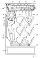
- FIG. 2 is the front side of the coin processing apparatus 1 (that is, the front side when the coin processing apparatus 1 is viewed from the front side as shown in FIG. 1).
- the right direction in FIG. 2 is the depth direction of the housing 1a.
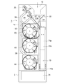
- FIG. 3 is a front view showing the internal configuration of the coin processing apparatus 1 when the coin processing apparatus 1 is viewed from the front side as shown in FIG.
- the coin processing device 1 includes a substantially rectangular parallelepiped housing 1 a, a coin insertion unit 10 for inserting coins from the outside of the housing 1 a, and a coin insertion unit 10.
- a storage and feeding unit 30 that feeds and stores coins thrown into the inside of the housing 1a and feeds the stored coins one by one is provided.
- the storing and feeding unit 30 stores coins between a rotating disk 32 that is inclined at a predetermined angle with respect to the vertical direction and is rotated in an inclined posture, and a surface 32 b of the rotating disk 32.
- a cover member 34 that forms a coin storage space 33. In the present embodiment, the cover member 34 can be opened in the storage and feeding unit 30.
- a deposit transport unit 20 that transports the coins fed from the storage and feeding unit 30 one by one is provided in the upper part of the housing 1 a.
- An identification unit 22 is provided for identifying the denomination, authenticity, correctness, new and old, front / back, and conveyance state of the coins conveyed by the deposit conveyance unit 20.
- the endless belt 20p is provided in the deposit conveyance part 20.
- the endless belt 20p is stretched around a plurality of pulleys, and the endless belt 20p is circulated in a counterclockwise direction in FIG. 2 by a motor attached to one pulley.
- the endless belt 20p is provided with a plurality of protruding members (not shown) at equal intervals, and one coin is hooked on one protruding member, so that one coin is placed on the transport surface. It can be transported.
- a plurality (specifically, six) storage and feeding sections 50 are provided below the deposit conveyance section 20 in the housing 1 a.
- Each storing and feeding unit 50 receives and stores coins from the depositing and conveying unit 20 via the chute 26 by the storing and selecting unit 24 provided in the depositing and conveying unit 20 based on the result of identifying the coins by the identifying unit 22. It has become so.
- the deposit transport unit 20 is provided with a reject sorting unit 27 that is a reject coin sorting unit, and the coins that are identified as fake coins (fake coins) by the identification unit 22 are rejected. 27 is sent to a coin dispensing section 72 described later via a reject coin chute (not shown).
- a return unit for returning rejected coins to the outside of the machine body may be provided in the vicinity of the coin throwing unit 72 separately from the coin throwing unit 72.
- the coin determined to be a fake coin by the identification unit 22 is sent as a reject coin to the return unit by the reject sorting unit 27 via the reject coin chute.
- each storing and feeding unit 50 feeds out coins stored in the storing and feeding unit 50 one by one. More specifically, each storage and feeding unit 50 stores coins between a rotating disk 52 that is inclined at a predetermined angle with respect to the vertical direction and is rotated in an inclined posture, and a surface 52 b of the rotating disk 52. And a cover member 54 that forms a coin storage space 53.
- the coin processing device 1 is provided with a coin throwing portion 72 for throwing coins outside the housing 1a on the front surface of the housing 1a. It has been. The operator can insert his / her hand into the inside of the coin dispensing unit 72 from the front side of the housing 1a, and thus the coins stored in the inside of the coin dispensing unit 72 can be stored in the operator. Can be taken out of the housing 1a by hand.
- the coin dispensing unit 72 may be provided with a shutter (not shown) for opening and closing the coin dispensing slot.
- a dispensing conveyance unit 70 that conveys the coins fed out from each storage and feeding unit 50 to the coin dispensing unit 72 is provided so as to straddle the side and bottom of each storage and feeding unit 50. Yes.
- the withdrawal / conveying unit 70 is provided below each storing and feeding unit 50 and extends in a substantially horizontal direction, and the coins sent from the first withdrawal / conveying part 70a are coined.
- a second dispensing / conveying portion 70b that conveys the dispensing portion 72.
- the withdrawal / conveyance unit 70 is composed of an endless belt 70p stretched around a plurality of pulleys.
- one endless belt 70p is provided so as to straddle the first withdrawal / conveyance portion 70a and the second withdrawal / conveyance portion 70b.
- the endless belt 70p is circulated and moved in both the clockwise and counterclockwise directions in FIG. 2 by a motor attached to one pulley.
- the endless belt 70p is provided with a plurality of protruding members (not shown) at equal intervals, and one or more coins are hooked by the endless belt 70p by hooking one or more coins on one protruding member. It can be transported.
- a recovery box (collection unit) 78 used as an overflow coin storage unit is provided below the dispensing transport unit 70.
- the collection box 78 can be pulled out in the horizontal direction toward the front side with respect to the collection box housing portion 3 provided below the housing 1a.
- the endless belt 70p circulates in the clockwise direction in FIG. 2, so that coins are sent from the first withdrawal conveyance portion 70a of the withdrawal conveyance portion 70 to the collection box 78. .
- the coins can be recovered together with the recovery box 78 by pulling the recovery box 78 from the recovery box storage unit 3 to the front side.
- an overflow chute 25 for sending coins directly from the depositing / conveying unit 20 to the dispensing / conveying unit 70 without passing through the storage / feeding units 50.
- the depositing transport unit 20 has an overflow sorting unit 23 for sorting coins sent to the overflow chute 25.
- the lower end portion of the overflow chute 25 is positioned above the endless belt 70 p of the dispensing conveyance unit 70.
- the coin is transported by the deposit transport unit 20.
- the coins in which the storing and feeding unit 50 corresponding to the denomination is full or near full are sorted by the overflow sorting unit 23 and the endless belt 70p of the withdrawal conveying unit 70 is used by the overflow chute 25.
- the coin sent on the endless belt 70p of the withdrawal conveyance part 70 by the overflow chute 25 is sent to the collection box 78 by the endless belt 70p.
- the deposit conveyance unit 20 stops the coin conveyance. Since the coins can be sent to the collection box 78 without doing so, it is possible to prevent the processing speed of the coins from being lowered.
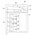
- FIG. 4 is the front side of the bill processing apparatus 101 (that is, the front side when the banknote processing apparatus 101 is viewed from the front side as shown in FIG. 1).
- the left direction in FIG. 4 is the depth direction of the housing 101a.
- the banknote processing apparatus 101 has a substantially rectangular parallelepiped casing 101a.
- the banknote handling apparatus 101 includes an upper unit 102 and a lower unit 103.
- the upper unit 102 includes a banknote insertion unit 110 and a banknote insertion unit 110 for inserting banknotes from the outside of the housing 101a.
- a transport unit 112 that transports bills inserted into the housing 101a, an identification unit 114 that is provided in the transport unit 112 and identifies bills transported by the transport unit 112, and a bill from the inside of the housing 101a to the outside.
- a bill dispensing unit 116 for dispensing is provided.
- a withdrawal reject unit 118 is connected to the transport unit 112.
- the bill insertion unit 110 is provided with a plurality of rollers such as a feed roller and a kicker roller, and the banknote placed on the bill insertion unit 110 in a stacked state by an operator is fed by the kicker roller.
- the kicked banknotes are kicked one by one toward the roller, and the kicked banknotes are fed one by one into the housing 101a by the feed roller.
- the banknotes fed into the housing 101 a by the banknote insertion unit 110 are transported one by one by the transport unit 112.
- the identification unit 114 identifies the denomination, authenticity, integrity, new / old, front / back, conveyance state, and the like of the banknotes conveyed by the conveyance unit 112.
- the banknotes identified by the identifying unit 114 are sent by the transport unit 112 to each storage and feeding unit 120 described later for each denomination, for example.
- each storing and feeding unit 120 stores bills sent from the transport unit 112 and can feed stored bills to the transport unit 112 one by one. More specifically, each storing and feeding unit 120 has one or a plurality of drums 122, and the banknotes sent from the transport unit 112 are put together with a banknote in a state where the banknotes are sandwiched between a pair of tapes one by one. The drum 122 is wound around.
- the banknotes sandwiched between the pair of tapes are fed out to the transport unit 112 one by one as the tape is unwound from the drum 122. become.
- a stacker type storing and feeding unit for stacking and storing banknotes is used instead of using the tape reel type storing and feeding unit 120 as shown in FIG. It may be.
- the transport unit 112 is provided with a collection unit 130.
- the collection unit 130 is used when collecting banknotes stored in each storage and feeding unit 120. More specifically, a banknote storage bag (not shown) for storing banknotes can be detachably attached to the collection unit 130, and the collection unit 130 passes through the conveyance unit 112 from each storage and feeding unit 120.
- the sent banknote is stored inside the banknote storage bag.
- banknotes of denominations that are not assigned to each storing and feeding unit 120 and overflow banknotes that cannot be stored because the corresponding denomination storing and feeding unit 120 is full are stored in the banknote storage bag mounted on the collecting unit 130. It is designed to be stored inside. Then, the banknotes are collected from the banknote processing apparatus 101 by taking out the banknote storage bags from the collection unit 130.
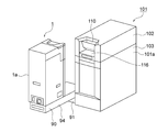
- the coin handling device 1 is placed on a gantry 90, and the coin handling device 1 placed on the gantry 90 is The orientation in the horizontal direction can be changed by 180 °. Details of the configuration of the gantry 90 will be described with reference to FIGS. 5 and 6.
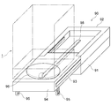
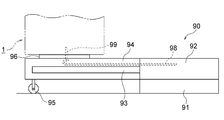
- 5 is a perspective view showing the configuration of the gantry 90 on which the coin processing apparatus 1 is placed
- FIG. 6 is a side view of the gantry 90 shown in FIG.
- the gantry 90 includes a base portion 91 that is fixed in position, for example, provided on the ground, a drawer portion 94 that can be pulled out to the near side in FIG. 5, and an upper portion of the base portion 91. And a turntable 96 provided on the upper surface of the lead-out portion 94.
- the lead-out portion 94 has a front side and a back side in FIG. 6 in the left-right direction).
- 5 and 6 are diagrams showing a state when the drawer portion 94 is pulled out from the accommodating portion 92 to the near side. More specifically, guide rails 93 are provided on both side surfaces of the drawer portion 94, and the drawer portion 94 moves to the near side and the back side in FIG. 5 along each guide rail 93.
- a pair of left and right casters 95 are provided on the bottom surface on the front side of the drawer portion 94, and the front end portion of the drawer portion 94 is supported by each caster 95.
- the turntable 96 is rotatable on a horizontal plane around an axis extending in the vertical direction, and the coin processing device 1 (indicated by a two-dot chain line in FIGS. 5 and 6) is placed on the upper surface of the turntable 96. It is supposed to be placed.
- such a turntable 96 functions as a rotation mechanism that rotates the coin processing device 1 around an axis extending in the vertical direction.
- the turntable 96 as a rotation mechanism can change the orientation of the coin processing apparatus 1 in the horizontal direction by 180 °.
- drawing-out part 94, and each caster 95 function as a slide mechanism which slides the coin processing apparatus 1 to a horizontal direction.
- the money handling system is provided with a direction detection unit 152 (see FIG. 7) that detects the direction of the coin handling device 1 with respect to the gantry 90.
- the orientation detection unit 152 detects the orientation of the coin processing device 1 with respect to the gantry 90 based on the rotational phase of the turntable 96.
- the coin processing apparatus 1 is facing the same direction as the banknote processing apparatus 101 (that is, the direction of the coin processing apparatus 1 is in the state shown in FIG. 1), or the coin processing apparatus. It is possible to detect whether 1 is facing in the opposite direction to the banknote handling apparatus 101 (that is, whether the orientation of the coin handling apparatus 1 is in the state shown in FIGS. 11 and 12).
- a flexible linear runner flex 98 is provided inside the drawer portion 94, and power is supplied from the banknote processing apparatus 101 to the coin processing apparatus 1.
- a signal line for transmitting and receiving signals between the coin processing apparatus 1 and the banknote processing apparatus 101 is accommodated inside the runner flex 98.
- the wiring and signal lines connecting the coin processing device 1 and the banknote processing device 101 are broken even if the drawing portion 94 is pulled out from the storage portion 92. Can be prevented.
- the center of the turntable 96 is provided with a wiring housing case 99 extending across the coin processing device 1 and the drawer portion 94 so as to penetrate the turntable 96.
- a wiring or signal line connecting between 1 and the banknote processing apparatus 101 is accommodated in the wiring accommodating case 99. Thereby, even if the turntable 96 rotates, it can prevent that the wiring and signal line which connect between the coin processing apparatus 1 and the banknote processing apparatus 101 are broken.
- the height level of the upper surface of the coin handling device 1 placed on the gantry 90 and the height level of the banknote handling device 101 are substantially the same size. Moreover, as shown in FIG. 1, when the coin processing apparatus 1 and the banknote processing apparatus 101 are arrange
- a coin control unit 80 for controlling each component of the coin processing device 1 is provided inside the housing 1 a of the coin processing device 1.
- the coin control unit 80 includes a coin insertion unit 10, a deposit transport unit 20, an identification unit 22, an overflow sorting unit 23, a storage sorting unit 24, a reject sorting unit 27, a storage feeding unit 30, and a storage feeding unit 50.
- the constituent members such as the dispensing conveyance unit 70 are connected.
- the signal which concerns on the coin identification result by the identification part 22 is sent to the coin control part 80, and the coin control part 80 is the coin insertion part 10, the deposit conveyance part 20, the overflow selection part 23, storage.
- These component members are controlled by sending command signals to the component members such as the sorting unit 24, the reject sorting unit 27, the storage and feeding unit 30, the storage and feeding unit 50, and the dispensing / conveying unit 70.
- the banknote control part 180 for controlling each structural member of the said banknote processing apparatus 101, the coin control part 80, and the banknote control part 180, respectively.
- a main body control unit 150 is provided inside the housing
- the banknote control unit 180 is connected to various components such as the banknote insertion unit 110, the transport unit 112, the identification unit 114, and the storage and feeding units 120. And the signal which concerns on the identification result of the banknote by the identification part 114 is sent to the banknote control part 180, Moreover, the banknote control part 180 is the banknote insertion part 110, the conveyance part 112, each accommodation feeding part 120, etc. These constituent members are controlled by sending command signals to the constituent members.
- the coin control part 80, the banknote control part 180, and the main body control part 150 are each connected by the signal wire
- the signal line connecting the coin control unit 80 and the main body control unit 150 is accommodated in the runner flex 98 and the wiring accommodation case 99.
- an orientation detection unit 152 a storage unit 154, and a communication interface unit 156 are connected to the main body control unit 150.
- the direction of the coin processing apparatus 1 with respect to the gantry 90 is detected by the direction detection unit 152, and the detection result by the direction detection unit 152 is sent to the main body control unit 150.
- the storage unit 154 stores the contents of coins and banknotes in the coin processing apparatus 1 and the banknote processing apparatus 101, and each storage and feeding part 50 of the coin processing apparatus 1 and each storage and feeding part 120 of the banknote processing apparatus 101. Information relating to the amount of money for each denomination of coins and banknotes is stored.
- the main body control unit 150 transmits and receives signals to and from an external device (specifically, for example, the POS register 200) provided separately from the coin processing device 1 and the banknote processing device 101 via the communication interface unit 156. Be able to. Further, in the money handling system according to the present embodiment, when the mobile terminal 210 such as a mobile phone, a smart phone, or iPad (registered trademark) can be used, the main body control unit 150 is a communication interface unit. Signals can be transmitted / received to / from the mobile terminal 210 via 156.
- an external device specifically, for example, the POS register 200
- the main body control unit 150 is a communication interface unit. Signals can be transmitted / received to / from the mobile terminal 210 via 156.
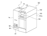
- FIG. 1 is a perspective view showing a state when the coin processing device 1 and the banknote processing device 101 are in the same direction. More specifically, as described above, when the coin processing apparatus 1 and the banknote processing apparatus 101 are arranged in the same direction, the coin and banknote input / output ports of the coin processing apparatus 1 and the banknote processing apparatus 101 are provided. The front side which is the side close to is arranged. Thus, when the coin processing apparatus 1 and the banknote processing apparatus 101 are in the same direction, the staff of the store processes the coins and banknotes from the front side in FIG. 1 in the coin processing apparatus 1 and the banknote processing apparatus 101, respectively. Will be able to do.
- both the coin processing device 1 and the banknote processing device 101 are normally arranged facing the store clerk side, and only during busy periods.
- the coin processing device 1 can be processed by the coin processing device 1 by changing the orientation of the coin processing device 1 in the horizontal direction by 180 °.
- the operator manually pulls the drawer portion 94 of the gantry 90 toward the front side from the storage portion 92 and moves the coin processing device 1 placed on the drawer portion 94.
- the banknote processing apparatus 101 is positioned closer to the front side than the front surface.
- the operator manually changes the horizontal direction of the coin processing apparatus 1 by 180 degrees.
- a turntable 96 is provided on the upper surface of the drawer portion 94, and the turntable 96 is rotatable along a horizontal plane about an axis extending in the vertical direction.
- the coin processing device 1 is placed on the upper surface of the turntable 96. For this reason, when the turntable 96 rotates by 180 ° about the axis extending in the vertical direction, the orientation of the coin processing apparatus 1 in the horizontal direction changes by 180 °.
- the operator manually pushes the drawer portion 94 of the gantry 90 toward the base portion 91.
- the rear surface of the coin processing device 1 that is, the front surface in FIG. 11
- the front surface of the banknote processing device 101 are aligned.
- the operator manually pushes the drawer portion 94 of the gantry 90 further to the back side.
- the front surface of the coin processing device 1 that is, the back surface in FIG. 11
- the rear surface of the banknote processing device 101 are aligned.
- the side surfaces of the coin processing device 1 and the banknote processing device 101 are aligned when viewed from the customer side (that is, the rear surface side in FIG.
- the coin handling device 1 is slid between the three positions by the slide mechanism (specifically, each guide rail 93, the drawer portion 94, and each caster 95). It has become. Three positions of the coin processing apparatus 1 will be described with reference to FIG. In FIG. 13, the left side is the store clerk side and the right side is the customer side. As shown in FIG. 13, when the coin processing apparatus 1 and the banknote processing apparatus 101 are arranged in opposite directions, the side surface on the customer side in the coin processing apparatus 1 and the banknote processing apparatus 101 is the same.
- the aligned first position P1 and the coin processing device 1 and the bill processing device 101 are arranged in the same direction, they are close to the coin inlet and the bill outlet in the two coin processing devices 1 and the bill processing device 101.
- the drawer portion 94 is slid between a second position P2 where the front side is aligned and a third position P3 where the direction of the coin processing device 1 in the horizontal direction can be changed by the turntable 96.
- the coin processing apparatus 1 and the banknote processing apparatus 101 are in a state as shown in FIG. 12
- the coin processing apparatus 1 is located at the first position P1 in FIG.
- the coin processing apparatus 1 and the banknote processing apparatus 101 are in a state as shown in FIG.
- the coin processing apparatus 1 is located at the second position P2 in FIG. Moreover, when the coin processing apparatus 1 and the banknote processing apparatus 101 are in a state as shown in FIG. 8, the coin processing apparatus 1 is located at the third position P3 in FIG. As described above, when the coin processing apparatus 1 is configured to slide between the three positions by the guide rails 93, the drawer portions 94, and the casters 95 as the slide mechanism, the first position P1 and the second position P1.
- the side surfaces of the coin processing device 1 and the banknote processing device 101 can be aligned on the customer side and the store clerk side at the position P2, and the horizontal direction of the coin processing device 1 is set to the banknote processing device 101 at the third position P3. It will be possible to change 180 ° without collision.
- the orientation detection unit 152 detects the orientation of the coin handling device 1 with respect to the gantry 90, and information related to the detection result is displayed on the monitor of the POS register 200 or a portable terminal. 210 is displayed on the display screen. Specifically, as shown in FIG. 1, when the coin processing device 1 is facing the store clerk side, the clerk can process coins and bills in the coin processing device 1 and the bill processing device 101. Is displayed on the monitor of the POS register 200 and the like. When the coin processing device 1 is facing the customer as shown in FIG. 12, a message indicating that the customer can process coins in the coin processing device 1 is not displayed on the monitor of the POS register 200 or illustrated. Displayed on an external display device or the like.
- the money is processed in a different manner depending on the direction of the coin handling apparatus 1 with respect to the gantry 90.
- the coin processing device 1 or the bill processing device 101 is used as a coin or bill loading process (that is, used as change).
- the coins and bills to be inserted can be inserted into the housings 1a and 101a by the coin insertion unit 10 and the bill insertion unit 110 and stored in the storage and feeding units 50 and 120.
- the coin processing device 1 cannot perform the coin loading process.
- the main body control unit determines whether or not the coin processing device 1 can execute a coin or bill loading process. 150, and information related to the determination result by the main body control unit 150 is sent to the coin control unit 80. And the coin control part 80 selectively prohibits performing the loading process of the coin in the coin processing apparatus 1 by controlling each structural member of the coin processing apparatus 1 based on the determination result by the main body control part 150. It has come to be.
- the coin processing device 1 when the coin processing device 1 faces the store clerk side, the coin processing device 1 has a collection box 78 as an overflow coin storage unit that stores overflow coins. Although it cannot be used, as shown in FIG. 12, when the coin processing device 1 is facing the customer side, the coin processing device 1 can use the collection box 78 as an overflow coin storage unit. It may be. More specifically, the main body control unit 150 determines whether or not the overflow coin can be sent to the collection box 78 based on the direction of the coin processing apparatus 1 with respect to the gantry 90 detected by the direction detection unit 152. The information related to the determination result by the main body control unit 150 is sent to the coin control unit 80.
- the coin control unit 80 selectively controls the constituent members of the coin processing device 1 based on the determination result by the main body control unit 150 to send the overflow coins to the collection box 78 in the coin processing device 1. Is now prohibited. Specifically, as shown in FIG. 1, when the orientation detection unit 152 detects that the coin processing device 1 is facing the store clerk side, the endless belt 70 p of the withdrawal transport unit 70 is illustrated. 2 circulates only in the counterclockwise direction, and as a result, coins are not sent from the withdrawal conveyance unit 70 to the collection box 78.
- the overflow coin is sent to the collection box 78.
- the coin processing device 1 when the coin processing device 1 is facing the store clerk side, the coin processing device 1 does not accept a command to start depositing money. However, when the coin processing device 1 is facing the customer as shown in FIG. 12, when it is detected that a coin has been inserted into the coin insertion unit 10, the coin processing device 1 deposits a coin. It may be possible to start processing. More specifically, on the basis of the orientation of the coin processing device 1 with respect to the gantry 90 detected by the orientation detection unit 152, when a coin is inserted into the coin insertion unit 10, the coin processing device 1 starts a coin deposit process.
- the main body control unit 150 determines whether or not it can be performed, and information related to the determination result by the main body control unit 150 is sent to the coin control unit 80. Then, the coin control unit 80 controls each component of the coin processing device 1 based on the determination result by the main body control unit 150, so that coins are inserted into the coin insertion unit 10 in the coin processing device 1.
- the coin processing apparatus 1 starts the coin deposit process on the condition that the deposit process is started or a command to start depositing money is accepted.
- the coin throwing unit It is desirable that the coin depositing process can be started simply by inserting a coin into the coin 10.
- the coin depositing apparatus 1 starts the coin depositing process on the condition that a command for starting the depositing of money has been accepted. It is desirable to be able to do that.
- one storage and feeding unit 50 among the plurality of storage and feeding units 50 in the coin processing apparatus 1 may be used as a false coin storage unit for storing fake coins.
- a false coin storage unit for storing fake coins.
- the coin processing apparatus 1 when the coin processing device 1 is facing the store clerk side as shown in FIG. 1, fake coins inserted into the housing 1 a are fake.
- the coin processing apparatus 1 When the coin processing apparatus 1 is facing the customer side as shown in FIG. 12, it can be sent to places other than the coin storage part (for example, the coin throwing part 72 and the collection box 78). May be configured to send the false coins inserted into the housing 1a only to the false coin storage unit.
- the main body control unit 150 determines the transport destination of the fake coins based on the direction of the coin processing apparatus 1 with respect to the gantry 90 detected by the direction detection unit 152. Information related to the determination result by the unit 150 is sent to the coin control unit 80. And the coin control part 80 controls each component of the coin processing apparatus 1 based on the discrimination
- the coin control part 80 controls each component of the coin processing apparatus 1 based on the discrimination
- the coin processing is performed in the coin processing apparatus 1 by the customer, the case of the coin processing apparatus 1 is not thrown out of the casing 1a without throwing out the false coins inserted into the casing 1a. Since it is necessary to store the coins in the body 1a separately from the true coins, the false coins inserted into the housing 1a are sent only to the false coin storage unit.
- the false coin is stored in the false coin storage unit. You may make it send to the coin throwing-out part 72, without sending, and the staff of this shop collect
- the shutter (not shown) for opening and closing a coin outlet is provided in the coin throwing-out part 72 of the coin processing apparatus 1, as shown in FIG.
- the shutter is not used and the coin dispensing unit 72 is always accessible, but the coin processing device 1 is on the customer side as shown in FIG.
- the shutter may be used when facing the camera. More specifically, based on the orientation of the coin processing device 1 with respect to the gantry 90 detected by the orientation detection unit 152, whether or not to use a shutter for opening and closing the coin outlet provided in the coin dispensing unit 72 is used.
- the main body control unit 150 discriminates the information, and information related to the discrimination result by the main body control unit 150 is sent to the coin control unit 80.
- the coin control part 80 opens and closes the coin outlet provided in the coin throwing-out part 72 by controlling each structural member of the coin processing apparatus 1 based on the discrimination
- the shutter is selectively used.
- the coin dispensing unit 72 uses a shutter for opening and closing the coin outlet, so that, for example, the customer can dispense the coin. If the user forgets to remove the coin from the unit 72, closing the shutter can prevent another customer from accidentally taking out the coin from the coin dispensing unit 72.
- the coin throwing unit 72 is provided with a take-in mechanism (not shown) that takes in the coins to be left in the coin throwing unit 72 of the coin processing apparatus 1 into the housing 1a. May be.
- a take-in mechanism (not shown) that takes in the coins to be left in the coin throwing unit 72 of the coin processing apparatus 1 into the housing 1a. May be.
- a taking-in mechanism is provided in the coin dispensing unit 72 in the coin processing apparatus 1, a coin throwing out is performed when the coin processing apparatus 1 is facing the store clerk side as shown in FIG.
- the forgotten coins remaining in the part 72 are not taken into the housing 1a by the take-in mechanism, but when the coin processing device 1 is facing the customer side as shown in FIG.
- the remaining forgotten coins may be taken into the housing 1a by the take-in mechanism.
- the main body control unit 150 determines whether or not to use the take-in mechanism provided in the coin dispensing unit 72 based on the orientation of the coin processing device 1 with respect to the gantry 90 detected by the orientation detection unit 152.
- the information related to the determination result by the main body control unit 150 is sent to the coin control unit 80.
- the coin control part 80 selectively uses the taking-in mechanism provided in the coin throwing-out part 72 by controlling each structural member of the coin processing apparatus 1 based on the discrimination
- a coin is dispensed by the customer in the coin processing apparatus 1, if the customer forgets to take a coin from the coin throwing unit 72, the forgotten coin that remains in the coin throwing unit 72 is removed.
- the coin processing apparatus 1 determines with the case where the coin processing apparatus 1 is facing the store attendant side as shown in FIG. 1, and the case where the coin processing apparatus 1 is facing the customer side as shown in FIG.
- the thresholds for determining whether or not the coin is a fake coin based on the coin identification result by the unit 22 may be different.
- a coin depositing process is performed in the coin processing apparatus 1 by setting the value to be stricter than the threshold when the main body control unit 150 determines whether or not it is a fake coin when the coin depositing process is performed.
- the main body control unit 150 determines whether or not the coin control unit 150 is a fake coin when the coin processing is performed in the coin processing apparatus 1 by a store clerk. Even if it is lowered, there is no particular problem.
- the coin processing device 1 is facing the store clerk side as shown in FIG. 1 and the coin processing device 1 is facing the customer side as shown in FIG.
- the upper limit value of the number of coins that can be gold may be different. Specifically, when a coin is dispensed in the coin processing apparatus 1 by a customer, the coins are withdrawn indefinitely by setting the upper limit value of the number of coins that can be dispensed to a predetermined value. Can be prevented. On the other hand, when the coin processing is performed in the coin processing apparatus 1 by a store clerk, the upper limit value of the number of coins that can be withdrawn is not provided, and the coins can be withdrawn without limitation. It is desirable.
- the frame 90 on which the money handling device (specifically, the coin handling device 1) is placed is placed in the horizontal direction of the money handling device.
- a direction changing mechanism for changing the direction in In this case, the direction in the horizontal direction of the money handling apparatus can be easily changed. If it demonstrates in detail, in the conventional money processing system, since the weight of the money processing apparatus (specifically, coin processing apparatus) is large, it was not easy to change the direction of the said money processing apparatus frequently. In particular, when a plurality of money handling devices are arranged side by side, or when a money handling device is placed adjacent to other equipment or a wall, the other money handling equipment or equipment, etc. will be in the way.
- the gantry 90 on which the money handling apparatus is placed is provided with a direction changing mechanism that changes the orientation of the money handling apparatus in the horizontal direction.
- the orientation in the direction can be easily changed.
- the orientation detection unit 152 that detects the orientation of the money handling device (specifically, the coin handling device 1) with respect to the gantry 90 is provided.
- the orientation of the money handling apparatus with respect to the gantry 90 is automatically recognized by the main body control unit 150 and the like.
- the direction changing mechanism rotates the money handling device (specifically, the coin handling device 1) about the axis extending in the vertical direction.
- a turntable 96 is included.
- the orientation of the money handling apparatus in the horizontal direction can be easily changed by rotating the turntable 96 around the axis extending in the vertical direction.
- the rotation mechanism constituted by the turntable 96 and the like can change the orientation of the money handling apparatus in the horizontal direction by 180 °.
- a slide mechanism (specifically, a slide mechanism (specifically, the coin handling device 1) is slid on the gantry 90 in the horizontal direction.
- the guide rails 93, the drawer portions 94, and the casters 95) are provided.
- the money handling apparatus is slid so as to move away from another money handling apparatus (specifically, the banknote handling apparatus 101) provided in parallel.
- the processing device is rotated, it can be prevented from colliding with another money handling device.
- two money handling devices are arranged adjacent to each other, and at least one of them.
- the coin handling device (specifically, the coin handling device 1) is placed on a gantry 90 provided with a direction changing mechanism.
- both the coin processing device 1 and the banknote processing device 101 are arranged facing the store clerk side, and only one coin processing device (specifically, coin Only the processing device 1) can be arranged facing the customer.
- the height level of the upper surface of each money handling apparatus is substantially the same. That is, the height level of the upper surface of the coin processing device 1 placed on the gantry 90 and the height level of the upper surface of the banknote processing device 101 are substantially the same size. In this case, the appearance of the money handling system including the coin handling device 1 and the banknote handling device 101 is improved in appearance.
- the money handling system As described above, when two money handling devices are arranged in the same direction (see FIG. 1), the money slot in these two money handling devices. And the front surface (that is, the side surface on the near side in FIG. 1) that is the side close to the outlet is aligned. In this case, the appearance of the money handling system composed of the coin handling device 1 and the bill handling device 101 is improved when viewed from the store clerk side.
- the money handling device is mounted on the gantry 90 on which at least one money handling device (specifically, the coin handling device 1) is placed.
- a slide mechanism (specifically, each guide rail 93, a drawer portion 94, and each caster 95) that slides in the horizontal direction is provided, and when two money handling apparatuses are arranged in opposite directions (FIG. 12). See), and the customer side surfaces (that is, the back surface shown in FIG. 12) of these two money handling apparatuses are aligned.
- the appearance of the money handling system composed of the coin handling device 1 and the banknote handling device 101 is improved when viewed from the customer side.
- the customer is compared with the state in which the coin processing device 1 is located behind the banknote processing device 101 as seen from the customer side as shown in FIG. 11.
- the coin processing device 1 makes it easy to process coins.
- the money handling apparatus (specifically, the coin handling apparatus 1) placed on the gantry 90 provided with the direction changing mechanism and the slide mechanism has two money handling apparatuses in opposite directions.
- the side surfaces of the coin processing device 1 and the banknote processing device 101 can be aligned on the customer side and the store clerk side at the first position P1 and the second position P2, respectively, and the coin processing is performed at the third position P3.
- the horizontal direction of the apparatus 1 can be changed by 180 ° without colliding with the banknote processing apparatus 101.
- wiring for connecting two money handling apparatuses (specifically, the coin handling apparatus 1 and the banknote handling apparatus 101) is provided.
- the wiring is provided between a gantry 90 provided with a direction changing mechanism (specifically, a turntable 96) and a money handling device (specifically, the coin handling device 1) placed on the gantry 90. It is to be passed through the direction change mechanism.
- the orientation of the money handling apparatus in the horizontal direction is changed by the orientation changing mechanism while maintaining the state where the two money handling apparatuses (specifically, the coin handling apparatus 1 and the banknote handling apparatus 101) are connected by wiring. Can be changed.
- the money is processed in a different manner depending on the direction of the money handling device (specifically, the coin handling device 1) with respect to the gantry 90. It may be.
- the manner in which money is processed may be automatically changed.
- money handling system according to the present embodiment is not limited to the above-described mode, and various changes can be made.
- the banknote handling device 101 is placed on the gantry 90 provided with the orientation changing mechanism.
- the orientation of the processing device 101 in the horizontal direction may be changed by the orientation changing mechanism.
- the coin handling device 1 and the bill handling device 101 are provided so as to be arranged side by side.
- the coin handling device 1 or the bill handling device 101 is used alone and used alone.
- the coin processing apparatus 1 or the banknote processing apparatus 101 may be placed on a gantry 90 provided with a direction changing mechanism.
- the installation of the slide mechanism composed of the guide rails 93, the drawer portions 94, and the casters 95 may be omitted. That is, a slide mechanism is not provided, and only a direction changing mechanism such as a turntable 96 is provided, and a gantry configured to change the horizontal direction of the money handling apparatus by the direction changing mechanism is used. Good.
Landscapes
- Physics & Mathematics (AREA)
- General Physics & Mathematics (AREA)
- Business, Economics & Management (AREA)
- Accounting & Taxation (AREA)
- Finance (AREA)
- Engineering & Computer Science (AREA)
- Computer Vision & Pattern Recognition (AREA)
- Cash Registers Or Receiving Machines (AREA)
Abstract
Ce système de traitement de devise comporte : un appareil de traitement de devises (par exemple, un appareil de traitement de pièces (1)) qui effectue un traitement de devises; et une base (90) sur laquelle l'appareil de traitement de devises est placé et qui est pourvue d'un mécanisme de changement d'orientation pour changer l'orientation de l'appareil de traitement de devises dans la direction horizontale.
Priority Applications (3)
| Application Number | Priority Date | Filing Date | Title |
|---|---|---|---|
| US16/099,899 US11222497B2 (en) | 2016-05-11 | 2017-04-24 | Money handling system |
| CN201780028755.4A CN109074700A (zh) | 2016-05-11 | 2017-04-24 | 货币处理系统 |
| EP17795940.0A EP3457367A4 (fr) | 2016-05-11 | 2017-04-24 | Système de traitement de devises |
Applications Claiming Priority (2)
| Application Number | Priority Date | Filing Date | Title |
|---|---|---|---|
| JP2016-095619 | 2016-05-11 | ||
| JP2016095619A JP2017204153A (ja) | 2016-05-11 | 2016-05-11 | 貨幣処理システム |
Publications (1)
| Publication Number | Publication Date |
|---|---|
| WO2017195579A1 true WO2017195579A1 (fr) | 2017-11-16 |
Family
ID=60267031
Family Applications (1)
| Application Number | Title | Priority Date | Filing Date |
|---|---|---|---|
| PCT/JP2017/016184 Ceased WO2017195579A1 (fr) | 2016-05-11 | 2017-04-24 | Système de traitement de devises |
Country Status (5)
| Country | Link |
|---|---|
| US (1) | US11222497B2 (fr) |
| EP (1) | EP3457367A4 (fr) |
| JP (1) | JP2017204153A (fr) |
| CN (1) | CN109074700A (fr) |
| WO (1) | WO2017195579A1 (fr) |
Families Citing this family (9)
| Publication number | Priority date | Publication date | Assignee | Title |
|---|---|---|---|---|
| JP2018049328A (ja) * | 2016-09-20 | 2018-03-29 | グローリー株式会社 | 貨幣処理装置および貨幣処理方法 |
| JP7043851B2 (ja) * | 2018-01-26 | 2022-03-30 | 富士電機株式会社 | 金銭処理装置 |
| JP2020190825A (ja) * | 2019-05-20 | 2020-11-26 | グローリー株式会社 | 硬貨処理装置 |
| USD998482S1 (en) * | 2020-01-31 | 2023-09-12 | Glory Ltd. | Currency processing machine |
| USD948605S1 (en) * | 2020-05-29 | 2022-04-12 | Glory Ltd. | Currency processing machine |
| USD952027S1 (en) * | 2020-05-29 | 2022-05-17 | Glory Ltd. | Currency processing machine |
| USD949961S1 (en) * | 2020-10-07 | 2022-04-26 | Glory Ltd. | Banknote handling machine |
| USD954144S1 (en) * | 2020-12-21 | 2022-06-07 | Glory Ltd. | Banknote handling machine |
| JP2025062520A (ja) * | 2023-10-02 | 2025-04-14 | グローリー株式会社 | 貨幣処理装置 |
Citations (5)
| Publication number | Priority date | Publication date | Assignee | Title |
|---|---|---|---|---|
| JPH04172594A (ja) * | 1990-11-07 | 1992-06-19 | Omron Corp | 電子式キャッシュレジスタの操作方向設定装置 |
| JP2001250142A (ja) * | 2000-03-03 | 2001-09-14 | Hitachi Ltd | 自動機 |
| JP2003177838A (ja) * | 2001-12-11 | 2003-06-27 | Matsushita Electric Ind Co Ltd | 窓口装置 |
| JP2012150846A (ja) * | 2012-05-17 | 2012-08-09 | Glory Ltd | 貨幣取引処理装置 |
| JP2013020301A (ja) * | 2011-07-07 | 2013-01-31 | Glory Ltd | 精算システム |
Family Cites Families (15)
| Publication number | Priority date | Publication date | Assignee | Title |
|---|---|---|---|---|
| JPH0350694A (ja) * | 1989-07-19 | 1991-03-05 | Hitachi Ltd | ユニット収納装置 |
| US5984177A (en) * | 1996-08-16 | 1999-11-16 | Transaction Technology, Inc. | Multiple configuration automatic teller machine |
| GB9811069D0 (en) * | 1998-05-23 | 1998-07-22 | Ncr Int Inc | Modular self service terminal |
| US20090057093A1 (en) * | 2007-08-27 | 2009-03-05 | Glory Ltd. | Bill/coin processing system |
| JP2010020370A (ja) * | 2008-07-08 | 2010-01-28 | Ishida Co Ltd | Pos端末装置 |
| AT508901B1 (de) * | 2009-10-20 | 2011-05-15 | Keba Ag | Fundamentsystem zur lastabtragenden aufnahme eines gehäuses oder von wenigstens einem gehäusemodul eines selbstbedienungsautomaten |
| JP2011238013A (ja) * | 2010-05-10 | 2011-11-24 | Nec Computertechno Ltd | 棒金収納管理装置 |
| US9058709B2 (en) | 2011-03-23 | 2015-06-16 | Glory Ltd. | Settlement system, settlement method, and cash settlement device |
| JP5813440B2 (ja) * | 2011-09-27 | 2015-11-17 | グローリー株式会社 | レジシステム |
| CN104574629B (zh) * | 2013-10-12 | 2017-10-03 | 山东新北洋信息技术股份有限公司 | 取币机构及使用该机构的硬币卷分发机 |
| US11138581B2 (en) * | 2014-01-10 | 2021-10-05 | Elo Touch Solutions, Inc. | Multi-mode point-of-sale device |
| CN105225363A (zh) * | 2014-06-23 | 2016-01-06 | 南京专创知识产权服务有限公司 | 超市自动收银装置 |
| JP6318969B2 (ja) * | 2014-08-18 | 2018-05-09 | 沖電気工業株式会社 | 現金処理装置 |
| JP6471449B2 (ja) * | 2014-10-10 | 2019-02-20 | 富士電機株式会社 | 貨幣処理装置及び貨幣処理装置の入金制御方法 |
| KR102426070B1 (ko) * | 2015-11-18 | 2022-07-28 | 삼성전자 주식회사 | 전자 장치 및 전자 장치의 디스플레이 설정 방법 |
-
2016
- 2016-05-11 JP JP2016095619A patent/JP2017204153A/ja active Pending
-
2017
- 2017-04-24 WO PCT/JP2017/016184 patent/WO2017195579A1/fr not_active Ceased
- 2017-04-24 US US16/099,899 patent/US11222497B2/en active Active
- 2017-04-24 EP EP17795940.0A patent/EP3457367A4/fr not_active Ceased
- 2017-04-24 CN CN201780028755.4A patent/CN109074700A/zh active Pending
Patent Citations (5)
| Publication number | Priority date | Publication date | Assignee | Title |
|---|---|---|---|---|
| JPH04172594A (ja) * | 1990-11-07 | 1992-06-19 | Omron Corp | 電子式キャッシュレジスタの操作方向設定装置 |
| JP2001250142A (ja) * | 2000-03-03 | 2001-09-14 | Hitachi Ltd | 自動機 |
| JP2003177838A (ja) * | 2001-12-11 | 2003-06-27 | Matsushita Electric Ind Co Ltd | 窓口装置 |
| JP2013020301A (ja) * | 2011-07-07 | 2013-01-31 | Glory Ltd | 精算システム |
| JP2012150846A (ja) * | 2012-05-17 | 2012-08-09 | Glory Ltd | 貨幣取引処理装置 |
Non-Patent Citations (1)
| Title |
|---|
| See also references of EP3457367A4 * |
Also Published As
| Publication number | Publication date |
|---|---|
| JP2017204153A (ja) | 2017-11-16 |
| CN109074700A (zh) | 2018-12-21 |
| US11222497B2 (en) | 2022-01-11 |
| EP3457367A1 (fr) | 2019-03-20 |
| EP3457367A4 (fr) | 2019-12-25 |
| US20190147683A1 (en) | 2019-05-16 |
Similar Documents
| Publication | Publication Date | Title |
|---|---|---|
| JP2017204153A (ja) | 貨幣処理システム | |
| JP6252056B2 (ja) | 紙幣入出金装置及び紙幣取引装置 | |
| JP6471449B2 (ja) | 貨幣処理装置及び貨幣処理装置の入金制御方法 | |
| US12190670B2 (en) | Money handling apparatus and money handling method | |
| JP2018081568A (ja) | 紙幣収納装置および紙幣処理機 | |
| JP2014170386A (ja) | 貨幣処理装置および貨幣処理方法 | |
| JP2012203666A (ja) | 紙幣処理装置および紙幣処理方法 | |
| JP6378537B2 (ja) | 硬貨回収用部材及び回収用部材付き硬貨処理装置 | |
| TW201642227A (zh) | 紙幣處理裝置 | |
| JP6735107B2 (ja) | 貨幣処理装置及び貨幣処理システム | |
| JP6781628B2 (ja) | 貨幣処理機および貨幣処理方法 | |
| JP2019003709A (ja) | 硬貨処理装置 | |
| JP2016081283A (ja) | 紙葉類処理装置 | |
| JP6496591B2 (ja) | 硬貨処理装置および処理システム | |
| JP6449597B2 (ja) | 硬貨処理装置および貨幣処理システム | |
| JP2019053642A (ja) | 貨幣処理装置、貨幣処理システムおよび貨幣処理方法 | |
| JPH05334331A (ja) | 金銭出納ステーション | |
| JP2018036995A (ja) | 貨幣処理機、貨幣処理システムおよび貨幣処理方法 | |
| JP6761326B2 (ja) | 貨幣処理機および貨幣処理方法 | |
| JP6681234B2 (ja) | 貨幣処理装置 | |
| JP6478561B2 (ja) | 有価媒体処理装置 | |
| JP2016081085A (ja) | 貨幣処理装置および貨幣処理方法 | |
| JP5584266B2 (ja) | 貨幣出金装置 | |
| JP2017162347A (ja) | 硬貨処理装置、硬貨処理システムおよび硬貨処理方法 | |
| JPH07296218A (ja) | 硬貨処理装置 |
Legal Events
| Date | Code | Title | Description |
|---|---|---|---|
| NENP | Non-entry into the national phase |
Ref country code: DE |
|
| 121 | Ep: the epo has been informed by wipo that ep was designated in this application |
Ref document number: 17795940 Country of ref document: EP Kind code of ref document: A1 |
|
| ENP | Entry into the national phase |
Ref document number: 2017795940 Country of ref document: EP Effective date: 20181211 |