WO2017195589A1 - Dispositif de commande d'angle d'inclinaison pour machine rotative hydraulique - Google Patents
Dispositif de commande d'angle d'inclinaison pour machine rotative hydraulique Download PDFInfo
- Publication number
- WO2017195589A1 WO2017195589A1 PCT/JP2017/016337 JP2017016337W WO2017195589A1 WO 2017195589 A1 WO2017195589 A1 WO 2017195589A1 JP 2017016337 W JP2017016337 W JP 2017016337W WO 2017195589 A1 WO2017195589 A1 WO 2017195589A1
- Authority
- WO
- WIPO (PCT)
- Prior art keywords
- spool
- receiving chamber
- pressure receiving
- tilt angle
- servo piston
- Prior art date
- Legal status (The legal status is an assumption and is not a legal conclusion. Google has not performed a legal analysis and makes no representation as to the accuracy of the status listed.)
- Ceased
Links
Images


Classifications
-
- F—MECHANICAL ENGINEERING; LIGHTING; HEATING; WEAPONS; BLASTING
- F04—POSITIVE - DISPLACEMENT MACHINES FOR LIQUIDS; PUMPS FOR LIQUIDS OR ELASTIC FLUIDS
- F04B—POSITIVE-DISPLACEMENT MACHINES FOR LIQUIDS; PUMPS
- F04B1/00—Multi-cylinder machines or pumps characterised by number or arrangement of cylinders
- F04B1/12—Multi-cylinder machines or pumps characterised by number or arrangement of cylinders having cylinder axes coaxial with, or parallel or inclined to, main shaft axis
- F04B1/26—Control
-
- F—MECHANICAL ENGINEERING; LIGHTING; HEATING; WEAPONS; BLASTING
- F04—POSITIVE - DISPLACEMENT MACHINES FOR LIQUIDS; PUMPS FOR LIQUIDS OR ELASTIC FLUIDS
- F04B—POSITIVE-DISPLACEMENT MACHINES FOR LIQUIDS; PUMPS
- F04B49/00—Control, e.g. of pump delivery, or pump pressure of, or safety measures for, machines, pumps, or pumping installations, not otherwise provided for, or of interest apart from, groups F04B1/00 - F04B47/00
- F04B49/12—Control, e.g. of pump delivery, or pump pressure of, or safety measures for, machines, pumps, or pumping installations, not otherwise provided for, or of interest apart from, groups F04B1/00 - F04B47/00 by varying the length of stroke of the working members
-
- F—MECHANICAL ENGINEERING; LIGHTING; HEATING; WEAPONS; BLASTING
- F04—POSITIVE - DISPLACEMENT MACHINES FOR LIQUIDS; PUMPS FOR LIQUIDS OR ELASTIC FLUIDS
- F04B—POSITIVE-DISPLACEMENT MACHINES FOR LIQUIDS; PUMPS
- F04B49/00—Control, e.g. of pump delivery, or pump pressure of, or safety measures for, machines, pumps, or pumping installations, not otherwise provided for, or of interest apart from, groups F04B1/00 - F04B47/00
- F04B49/06—Control using electricity
Definitions
- the present invention relates to a tilt angle control device for a variable capacity hydraulic rotating machine.
- ⁇ Variable capacity hydraulic rotating machines include a hydraulic pump that can change the discharge flow rate according to the tilt angle and a hydraulic motor that can change the rotation speed according to the tilt angle.
- the tilt angle of such a hydraulic rotary machine is controlled by a tilt angle control device.
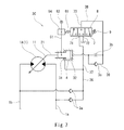
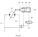
- Patent Document 1 discloses a tilt angle control device 100 for a hydraulic motor 110 as shown in FIG.
- the tilt angle control device 100 switches the tilt angle of the hydraulic motor 110 in two steps by an electric signal.
- the tilt angle control device 100 includes a servo piston 120 that moves in a flow rate increasing direction that increases the tilt angle of the hydraulic motor 110 and a flow rate decreasing direction that decreases the tilt angle.
- a housing 130 forming a first pressure receiving chamber 131 and a second pressure receiving chamber 132.
- the first pressure receiving chamber 131 is for moving the servo piston 120 in the flow rate increasing direction
- the second pressure receiving chamber 132 is for moving the servo piston 120 in the flow rate decreasing direction.
- the cross-sectional area of the second pressure receiving chamber 132 is larger than the cross-sectional area of the first pressure receiving chamber 131.
- a hydraulic pressure (the higher pressure of the pair of supply / discharge passages 111 and 112) flowing into the hydraulic motor 110 is guided.
- the second pressure receiving chamber 132 is connected to the electromagnetic valve 140.
- the solenoid valve 140 communicates the second pressure receiving chamber 132 with the tank when the command current is not supplied. Thereby, the tilt angle of the hydraulic motor 110 is maximized.
- the electromagnetic valve 140 guides the hydraulic pressure flowing into the hydraulic motor 110 to the second pressure receiving chamber 132 when the command current is supplied. As a result, the tilt angle of the hydraulic motor 110 is minimized.
- an object of the present invention is to make it possible to adjust the tilt angle of the hydraulic rotating machine to an arbitrary angle according to an electric signal.
- the present invention provides a servo piston that moves in a flow rate increasing direction that increases a tilt angle of a variable displacement hydraulic rotating machine and a flow rate decreasing direction that decreases the tilt angle, and the servo
- a first housing that forms a pressure receiving chamber with the servo piston, and a second housing hole that is adjacent to the first housing on the side of the servo piston and extends parallel to the axial direction of the servo piston.
- a housing a supply passage formed in a casing of the hydraulic rotary machine, a reference flow path communicating with the first pressure receiving chamber, and the housing hole, the second pressure receiving chamber being A spool that allows the second pressure receiving chamber to communicate with one of the supply path and the tank according to the moving direction when moved from a pressure adjusting position that is cut off from both the supply path and the tank, and a feedback piston disposed in the accommodation hole And a feedback lever that connects the servo piston and the feedback piston, a spring that biases the spool and the feedback lever away from each other, and a pressing force proportional to a command current from the opposite side of the spring.
- a tilt angle control device for a hydraulic rotary machine comprising a solenoid that presses the spool.
- the servo piston moves, the feedback piston also moves, so the urging force of the spool by the spring changes. Then, when the pressing force of the spool by the solenoid and the biasing force of the spool by the spring are balanced, the spool is again positioned at the pressure adjusting position.
- the servo piston moves by the amount of change in the command current to the solenoid (that is, the tilt angle of the hydraulic rotating machine changes). Therefore, the tilt angle of the hydraulic rotary machine can be adjusted to an arbitrary angle according to the electrical signal.
- the tilt angle control device is a sleeve that is disposed in the accommodation hole and through which the spool is inserted, and is connected to the input port connected to the reference flow path and the second pressure receiving chamber.
- a sleeve having an output port may be further provided, and the spool may have a land portion that opens and closes the output port.
- the spool has an enlarged diameter portion at an end portion on the solenoid side
- the solenoid includes a plunger for pressing the spool, a fixed magnetic pole penetrating the plunger, and a movable iron core to which the plunger is fixed.
- a cylindrical portion surrounding the enlarged diameter portion of the spool, and the tilt angle control device is disposed in the receiving hole and is pressed against the cylindrical portion of the solenoid by a spring
- the tilt angle is not affected by the command current near the stroke end due to the adsorption of the movable iron core to the fixed magnetic pole. May change rapidly. This phenomenon occurs even when a current dither is applied to the solenoid (when a command current to the solenoid is vibrated).
- the stroke end of the spool is set using a stopper ring arranged in the accommodation hole, the continuous change of the tilt angle by the command current can be ensured even in the vicinity of the stroke end.
- the tilt angle of the hydraulic rotary machine can be adjusted to an arbitrary angle according to the electric signal.
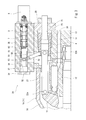
- FIG. 1 is a hydraulic circuit diagram of a tilt angle control device for a hydraulic rotary machine according to an embodiment of the present invention. It is a graph which shows the relationship between the command current to the solenoid in 1st Embodiment, and a tilt angle. It is sectional drawing of the tilt angle control apparatus shown in FIG.
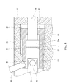
- FIG. 4 is an enlarged view around a servo piston in FIG. 3.
- FIG. 4 is an enlarged view around the spool in FIG. 3.
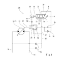
- FIG. 1 shows a tilt angle control device 2A of a variable displacement hydraulic rotating machine 1 according to an embodiment of the present invention.
- the hydraulic rotary machine 1 is a hydraulic motor 1A.
- the hydraulic rotary machine 1 may be a hydraulic pump.
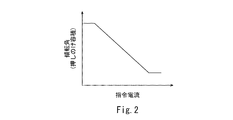
- the tilt angle control device 2A is a negative type in which a command current to a solenoid 9 described later and a tilt angle (that is, displacement volume) have a negative correlation as shown in FIG.
- the tilt angle control device of the present invention may be a positive type in which the command current and the tilt angle have a positive correlation.
- the hydraulic motor 1A has a structure in which a swash plate 11 and a cylinder block 12 are encased in a first casing 13 and a second casing.
- a pair of supply / discharge passages 1 a and 1 b is formed in the first casing 13 that supports the cylinder block 12.
- the second casing 14 is a cover having a hollow inside.
- a space surrounded by the first casing 13 and the second casing 14 is filled with hydraulic fluid (typically hydraulic fluid) for operating the hydraulic motor 1A, and communicates with the tank.
- the tilt angle control device 2A includes a first housing 3A integrated with the first casing 13 of the hydraulic motor 1A, and a second housing 3B attached to the first housing 3A.
- the first housing 3 ⁇ / b> A may be a separate body from the first casing 13.
- the second housing 3B may be integrated with the first housing 3A.
- the servo piston 4 is slidably held in the first housing 3A.
- the second housing 3B is adjacent to the first housing 3A on the side of the servo piston 4.
- the axial direction of the servo piston 4 is parallel to the axial direction of the hydraulic motor 1A, but the axial direction of the servo piston 4 may be inclined with respect to the axial direction of the hydraulic motor 1A.
- the second casing 14 side left side in FIG. 3) is referred to as the front
- the first casing 13 side (right side in FIG. 3) is referred to as the rear.
- the servo piston 4 is connected to the swash plate 11 of the hydraulic motor 1A by a rod 21 extending in the front-rear direction. More specifically, the front end of the rod 21 is connected to the swash plate 11 by a pin 22a, and the rear end of the rod 21 is connected to the front end of the servo piston 4 by a pin 22b. However, instead of the connection by the pin 22a, the swash plate 11 may be pressed against the front end portion of the rod 21 by a spring. In this case, the rod 21 may be omitted.
- the tilt angle of the hydraulic motor 1A which is the angle of the swash plate 11 with respect to the plane orthogonal to the axial direction of the hydraulic motor 1A, increases, and when the servo piston 4 moves forward, The tilt angle of the pressure motor 1A is reduced. That is, with respect to the servo piston 4, the rear is the flow rate increasing direction and the front is the flow rate decreasing direction.
- the first housing 3 ⁇ / b> A forms a first pressure receiving chamber 31 and a second pressure receiving chamber 32 with the servo piston 4.
- the first pressure receiving chamber 31 is for moving the servo piston 4 in the flow rate increasing direction (backward)
- the second pressure receiving chamber 32 is for moving the servo piston 4 in the flow rate decreasing direction (forward). is there.
- the effective cross-sectional area of the second pressure receiving chamber 32 is larger than the effective cross-sectional area of the first pressure receiving chamber 31. The effective cross-sectional area will be described later.
- the servo piston 4 has a peripheral wall 41 extending in the front-rear direction, a bottom wall 42 that closes the inside of the peripheral wall 41 from the rear, and a flange 43 that protrudes radially outward from the rear end portion of the peripheral wall 41.
- the rear surface of the flange 43 is flush with the rear surface of the bottom wall 42, but they may be displaced in the front-rear direction.
- the rear end portion of the rod 21 described above is inserted into the front end portion of the peripheral wall 41.
- the first pressure receiving chamber 31 described above is a space facing the front surface of the flange 43 and the outer peripheral surface of the peripheral wall 41
- the second pressure receiving chamber 32 is a space facing the rear surface of the flange 43 and the rear surface of the bottom wall 42.
- the effective sectional area of the first pressure receiving chamber 31 described above is an area between the outer peripheral surface of the flange 43 and the outer peripheral surface of the peripheral wall 41 when viewed from the axial direction of the servo piston 4.
- the cross-sectional area is an area between the outer peripheral surface of the flange 43 and the peripheral surface of a shaft portion 23b of the defining member 23 described later when viewed from the axial direction of the servo piston 4.
- the first pressure receiving chamber 31 is connected to the pair of supply / discharge paths 1a and 1b by the reference flow path 36.
- the reference flow path 36 includes one main flow path connected to the first pressure receiving chamber 31 and two branch paths connected to the pair of supply / discharge paths 1a and 1b. Each branch passage is provided with a check valve 3a. That is, the reference flow path 36 communicates the first pressure receiving chamber 31 with the higher pressure supply / discharge path of the pair of supply / discharge paths 1 a, 1 b.
- the higher pressure functions as a supply passage for supplying hydraulic fluid to the hydraulic motor 1A, and the lower pressure as a discharge passage for discharging hydraulic oil from the hydraulic motor 1A.
- the second pressure receiving chamber 32 is connected to an output port 73 of the sleeve 7 which will be described later by a pressure adjusting path 38.
- the pressure adjusting path 38 will be described later.
- Servo piston 4 can move forward until it comes into contact with regulating member 23. That is, the defining member 23 defines the minimum tilt angle.
- the defining member 23 is a rod-shaped member extending in the front-rear direction.
- the defining member 23 includes a head 23 a located in the peripheral wall 41 of the servo piston 4, and a shaft portion 23 b that extends rearward from the head 23 a through the bottom wall 42. Yes.
- a screw thread (not shown) is formed on the rear portion of the shaft portion 23b.
- the defining member 23 is fixed to the first housing 3 ⁇ / b> A via a fixing member 24 having a screw hole and a nut 25.
- the second housing 3 ⁇ / b> B is provided with a receiving hole 33 extending in parallel with the axial direction of the servo piston 4.
- the accommodation hole 33 penetrates the second housing 3B in the front-rear direction.
- the front opening of the receiving hole 33 is closed by a cap 34 attached to the front surface of the second housing 3B, and the rear opening of the receiving hole 33 is closed by a solenoid 9 attached to the rear face of the second housing 3B. ing.
- the feedback piston 54 In the accommodation hole 33, the feedback piston 54, the sleeve 7 and the spool 8 are arranged.
- the feedback piston 54 is located on the front side of the accommodation hole 33, and the sleeve 7 is located on the rear side of the accommodation hole 33.
- the spool 8 is inserted through the sleeve 7.
- a first spring 61 and a spring seat 62 are disposed between the feedback piston 54 and the spool 8.
- the feedback piston 54 is slidably held in the second housing 3B.
- the feedback piston 54 is connected to the servo piston 4 by a feedback lever 51.
- the feedback lever 51 has a length straddling the servo piston 4 and the feedback piston 54 and is supported by a pin 52 so as to be swingable at a substantially central position.
- the pin 52 is fixed to the second housing 3B.
- the feedback lever 51 has one end that engages with the servo piston 4.
- An engagement hole 44 (see FIG. 4) is formed in the front end portion of the peripheral wall 41 of the servo piston 4, and one end of the feedback lever 51 is inserted into the engagement hole 44.
- an engagement pin 53 is provided at the other end of the feedback lever 51.
- the feedback piston 54 is a tubular member, and is provided with a slit 55 extending in a direction orthogonal to the axial direction.
- An engagement pin 53 provided at the other end of the feedback lever 51 is engaged with the slit 55. Therefore, when the servo piston 4 moves forward, the feedback piston 51 moves backward by the clockwise swing of the feedback lever 51 in FIG. 3, and when the servo piston 4 moves backward, the feedback lever 51 in FIG.
- the feedback piston 54 moves forward by the counterclockwise swing.
- a stepped portion 56 is formed on the inner peripheral surface of the feedback piston 54 by expanding the diameter of the rear portion, and the front portion of the first spring 61 is inserted into the stepped portion 56.
- the first spring 61 presses the front end portion of the spool 8 via the spring seat 62.
- the first spring 61 biases the feedback piston 54 and the spool 8 so as to be separated from each other.
- the first spring 61 may directly press the front end portion of the spool 8.
- a ring-shaped protrusion 35 is formed substantially at the center of the accommodation hole 33.
- the sleeve 7 is pressed against the protrusion 35 by a second spring 63 disposed in the accommodation hole 33.
- a tank port 72, an output port 73, and an input port 71 are formed in this order from the front side.
- Each of the tank port 72, the output port 73, and the input port 71 includes a circumferentially continuous groove formed on the outer peripheral surface of the sleeve 7 and a plurality of through holes extending from the groove to the inner peripheral surface of the sleeve 7. Is done.
- the input port 71 is connected to the main flow path of the reference flow path 36 by the input path 37, and the tank port 72 is connected to the tank by the tank path 74.
- the contact between the inner side of the sleeve 7 and the front side of the projection 35 of the accommodation hole 33 may be cut off by the contact of the spring seat 62 with the sleeve 7.
- the tank port 72 is for coping with the disconnection. However, the tank port 72 can be omitted when communication between the inside of the sleeve 7 and the front side of the projection 35 of the accommodation hole 33 is always ensured.
- the output port 73 is connected to the second pressure receiving chamber 32 by the pressure adjusting path 38.
- the pressure regulating path 38 is provided with a throttle 3b.
- the pressure adjusting path 38 is connected to a bypass path 39 that bypasses the throttle 3b.
- the bypass passage 39 is provided with a check valve 3c that allows a flow from the second pressure receiving chamber 32 to the output port 73 but prohibits a flow from the output port 73 to the second pressure receiving chamber 32.
- the spool 8 is normally located at a pressure adjusting position where the second pressure receiving chamber 32 is cut off from both the supply path (the higher pressure of the supply / discharge paths 1a and 1b) and the tank. Then, when the spool 8 moves from the pressure adjusting position, the spool 8 communicates with the one of the supply path and the tank according to the moving direction.
- the spool 8 includes a first small diameter portion 81, a first land portion 82, a second small diameter portion 83, a second land portion 84, a third small diameter portion 85, and an enlarged diameter portion 86. These portions 81 to 86 are arranged in this order from the front side. That is, the enlarged diameter portion 86 is located at the rear end portion (end portion on the solenoid 9 side) of the spool 8.
- the first land portion 82 closes the output port 73 when the spool 8 is located at the pressure adjusting position, and opens the output port 73 when the spool 8 moves from the pressure adjusting position.
- the output port 73 passes through the annular flow path between the first small diameter portion 81 and the inner peripheral surface of the sleeve 7 and the front side portion of the housing hole 33 and the tank It communicates with port 72.
- the output port 73 communicates with the input port 71 through the annular flow path between the second small diameter portion 83 and the inner peripheral surface of the sleeve 7.
- the second land portion 84 serves to close the gap between the second small diameter portion 83 and the inner peripheral surface of the sleeve 7 from the rear.
- the solenoid 9 presses the spool 8 from the opposite side to the first spring 61 with a pressing force proportional to the command current supplied to the solenoid 9.
- the solenoid 9 includes a plunger 93 extending in the front-rear direction for pressing the rear end portion of the spool 8, a fixed magnetic pole 92 penetrating the plunger 93, and a rear end of the plunger 93. Includes a movable iron core 94 that is fixed.
- the solenoid 9 includes a cylindrical portion 91 that is inserted into the accommodation hole 33 and surrounds the enlarged diameter portion 86 of the spool 8.
- a stopper ring 64 is disposed in the accommodation hole 33 in the vicinity of the cylindrical portion 91.
- the stopper ring 64 is pressed against the cylindrical portion 91 by the second spring 63 described above.
- the inner diameter of the stopper ring 64 is smaller than the diameter of the enlarged diameter portion 86 of the spool 8.
- a gap S2 is formed between the enlarged diameter portion 86 of the spool 8 and the stopper ring 64.
- the gap S2 is smaller than the gap S1 between the movable iron core 94 of the solenoid 9 and the fixed magnetic pole 92. For this reason, when the command current is supplied to the solenoid 9 and the movable iron core 94 is advanced toward the fixed magnetic pole 92, the diameter-expanded portion 86 of the spool 8 stops the stopper before the movable iron core 94 contacts the fixed magnetic pole 92. It abuts on the ring 64.
- the servo piston 4 moves by the amount of change in the command current to the solenoid 9 (that is, the tilt angle of the hydraulic motor 1A changes). Therefore, the tilt angle of the hydraulic motor 1A can be adjusted to an arbitrary angle according to the electrical signal.
- the position of the servo piston 4 is fed back by the biasing force of the first spring 61, so that the stroke of the spool 8 is sufficient even if it is short. Therefore, a small solenoid 9 can be used.
- a stopper ring 64 for contacting the enlarged diameter portion 86 of the spool 8 is disposed in the accommodation hole 33.
- the command current is increased in the vicinity of the stroke end due to the adsorption of the movable iron core 94 to the fixed magnetic pole 92. Regardless of this, the tilt angle may change abruptly. This phenomenon occurs even when current dither is applied to the solenoid 9.
- the stroke end of the spool 8 is set using the stopper ring 64 disposed in the accommodation hole 33, the continuous change of the tilt angle by the command current can be secured even in the vicinity of the stroke end. .
- the reference flow path 36 may be a single flow path branched from the discharge path 1d.
- the tilt angle control device 2B of the hydraulic pump 1B can be realized.
- the hydraulic pump 1B has the same structure as the hydraulic motor 1A except that it has a suction path 1c and a discharge path 1d instead of the pair of supply / discharge paths 1a and 1b.
- a pin 52 for swingably supporting the feedback lever 51 is disposed on the opposite side of the servo piston 4 with respect to the feedback piston 54, and the input port 71 and the tank port 72 of the sleeve 7 are connected. If the positions are switched, the positive tilt angle control device 2C can be realized. This modification can also be applied to the tilt angle control device 2B of the hydraulic pump 1B shown in FIG.
- the sleeve 7 may be omitted, and the input port 71, the tank port 72, and the output port 73 may be formed in the second housing 3B.
Landscapes
- Engineering & Computer Science (AREA)
- Mechanical Engineering (AREA)
- General Engineering & Computer Science (AREA)
- Reciprocating Pumps (AREA)
- Control Of Positive-Displacement Pumps (AREA)
Abstract
L'invention concerne un dispositif de commande d'angle d'inclinaison pour une machine rotative hydraulique, comprenant : un piston d'asservissement qui se déplace dans la direction d'augmentation de débit et la direction de diminution de débit ; un premier logement qui forme une première chambre de réception de pression et une seconde chambre de réception de pression entre le premier logement et le piston d'asservissement ; un second boîtier dans lequel un trou de stockage s'étendant en parallèle avec la direction axiale du piston d'asservissement est prévu ; un trajet d'écoulement de référence qui raccorde un trajet d'alimentation formé dans un boîtier de la machine rotative hydraulique et la première chambre de réception de pression ; une bobine qui est disposée dans le trou de stockage et qui, lorsqu'elle est déplacée depuis la position de réglage de pression, raccorde la seconde chambre de réception de pression au trajet d'alimentation ou à un réservoir en fonction de la direction de déplacement ; un piston de retour disposé dans le trou de stockage et raccordé au piston d'asservissement par le biais d'un levier de retour ; un ressort qui sollicite la bobine et le levier de retour de manière à les séparer l'un de l'autre ; et un solénoïde qui presse la bobine depuis le côté opposé du ressort par une force de pression proportionnelle à un courant de commande.
Applications Claiming Priority (2)
| Application Number | Priority Date | Filing Date | Title |
|---|---|---|---|
| JP2016-094712 | 2016-05-10 | ||
| JP2016094712A JP6749137B2 (ja) | 2016-05-10 | 2016-05-10 | 液圧回転機械の傾転角制御装置 |
Publications (1)
| Publication Number | Publication Date |
|---|---|
| WO2017195589A1 true WO2017195589A1 (fr) | 2017-11-16 |
Family
ID=60266591
Family Applications (1)
| Application Number | Title | Priority Date | Filing Date |
|---|---|---|---|
| PCT/JP2017/016337 Ceased WO2017195589A1 (fr) | 2016-05-10 | 2017-04-25 | Dispositif de commande d'angle d'inclinaison pour machine rotative hydraulique |
Country Status (2)
| Country | Link |
|---|---|
| JP (1) | JP6749137B2 (fr) |
| WO (1) | WO2017195589A1 (fr) |
Families Citing this family (2)
| Publication number | Priority date | Publication date | Assignee | Title |
|---|---|---|---|---|
| JP7051475B2 (ja) * | 2018-02-09 | 2022-04-11 | ナブテスコ株式会社 | 油圧ポンプ |
| US12331740B2 (en) * | 2022-12-05 | 2025-06-17 | Hamilton Sundstrand Corporation | Variable displacement pumps |
Citations (4)
| Publication number | Priority date | Publication date | Assignee | Title |
|---|---|---|---|---|
| JPS59140975A (ja) * | 1983-11-29 | 1984-08-13 | Kayaba Ind Co Ltd | パイロツト切換弁のダンピング装置 |
| JPS643089U (fr) * | 1987-06-23 | 1989-01-10 | ||
| JPH0482384U (fr) * | 1990-11-29 | 1992-07-17 | ||
| WO2006129431A1 (fr) * | 2005-05-30 | 2006-12-07 | Hitachi Construction Machinery Co., Ltd. | Machine rotative hydraulique à plateau oscillant à déplacement variable |
-
2016
- 2016-05-10 JP JP2016094712A patent/JP6749137B2/ja active Active
-
2017
- 2017-04-25 WO PCT/JP2017/016337 patent/WO2017195589A1/fr not_active Ceased
Patent Citations (4)
| Publication number | Priority date | Publication date | Assignee | Title |
|---|---|---|---|---|
| JPS59140975A (ja) * | 1983-11-29 | 1984-08-13 | Kayaba Ind Co Ltd | パイロツト切換弁のダンピング装置 |
| JPS643089U (fr) * | 1987-06-23 | 1989-01-10 | ||
| JPH0482384U (fr) * | 1990-11-29 | 1992-07-17 | ||
| WO2006129431A1 (fr) * | 2005-05-30 | 2006-12-07 | Hitachi Construction Machinery Co., Ltd. | Machine rotative hydraulique à plateau oscillant à déplacement variable |
Also Published As
| Publication number | Publication date |
|---|---|
| JP6749137B2 (ja) | 2020-09-02 |
| JP2017203399A (ja) | 2017-11-16 |
Similar Documents
| Publication | Publication Date | Title |
|---|---|---|
| JP6613135B2 (ja) | 斜板ポンプの容量調整装置 | |
| US8100142B2 (en) | Bleed-type electromagnetic valve | |
| KR101702250B1 (ko) | 펌프 용적 제어 장치 | |
| JP2012154389A (ja) | スプールバルブ | |
| WO2019216193A1 (fr) | Soupape de régulation de débit électromagnétique | |
| WO2014147987A1 (fr) | Soupape d'absorption des chocs | |
| WO2017195589A1 (fr) | Dispositif de commande d'angle d'inclinaison pour machine rotative hydraulique | |
| CN109790931B (zh) | 滑阀和阀系统 | |
| JP3820273B2 (ja) | 油圧ポンプの流量制御弁 | |
| JP7033463B2 (ja) | スプール弁装置 | |
| JP4998315B2 (ja) | 電磁弁 | |
| JP6154874B2 (ja) | バルブ | |
| JP6284469B2 (ja) | 油圧回路 | |
| JP2010230019A (ja) | パイロットバルブ | |
| JP2011163433A (ja) | 電磁比例絞り弁 | |
| JP4998366B2 (ja) | 電磁弁 | |
| JP2008534887A (ja) | 方向制御弁および方向制御弁を備えた制御装置 | |
| JP3758109B2 (ja) | 減圧弁 | |
| JP2019196777A (ja) | スプール弁 | |
| EP3594541A1 (fr) | Soupape de réduction de pression électromagnétique et dispositif de commande de pression de fluide comprenant une soupape de réduction de pression électromagnétique | |
| CN220268070U (zh) | 集成式压力补偿阀 | |
| JP2012067890A (ja) | 減圧弁装置 | |
| JP2003227459A (ja) | 斜板形アキシャルピストンポンプの制御装置 | |
| KR101925516B1 (ko) | 차량용 보조제동장치의 유압밸브 | |
| JP4871774B2 (ja) | リリーフ弁 |
Legal Events
| Date | Code | Title | Description |
|---|---|---|---|
| NENP | Non-entry into the national phase |
Ref country code: DE |
|
| 121 | Ep: the epo has been informed by wipo that ep was designated in this application |
Ref document number: 17795950 Country of ref document: EP Kind code of ref document: A1 |
|
| 122 | Ep: pct application non-entry in european phase |
Ref document number: 17795950 Country of ref document: EP Kind code of ref document: A1 |