WO2017195599A1 - テープ巻付装置及びテープ巻付方法 - Google Patents
テープ巻付装置及びテープ巻付方法 Download PDFInfo
- Publication number
- WO2017195599A1 WO2017195599A1 PCT/JP2017/016521 JP2017016521W WO2017195599A1 WO 2017195599 A1 WO2017195599 A1 WO 2017195599A1 JP 2017016521 W JP2017016521 W JP 2017016521W WO 2017195599 A1 WO2017195599 A1 WO 2017195599A1
- Authority
- WO
- WIPO (PCT)
- Prior art keywords
- tape
- holding
- receiving
- winding
- cutting
- Prior art date
- Legal status (The legal status is an assumption and is not a legal conclusion. Google has not performed a legal analysis and makes no representation as to the accuracy of the status listed.)
- Ceased
Links
Images


Classifications
-
- H—ELECTRICITY
- H01—ELECTRIC ELEMENTS
- H01B—CABLES; CONDUCTORS; INSULATORS; SELECTION OF MATERIALS FOR THEIR CONDUCTIVE, INSULATING OR DIELECTRIC PROPERTIES
- H01B13/00—Apparatus or processes specially adapted for manufacturing conductors or cables
- H01B13/22—Sheathing; Armouring; Screening; Applying other protective layers
- H01B13/26—Sheathing; Armouring; Screening; Applying other protective layers by winding, braiding or longitudinal lapping
Definitions
- This invention relates to a technique for winding a tape around an object.
- Patent Document 1 discloses a tape winding device for winding a tape around an electric wire.
- This tape winding apparatus includes a rotating plate shaped like a U-shaped plate and a mechanism for rotating the rotating plate. In a state where the electric wire is arranged in the notch of the rotating plate, the tip of the tape is bonded to the electric wire, and the rotating plate rotates around the electric wire in this state, whereby the tape is wound around the electric wire.
- the present invention aims to provide a technique for suitably winding a tape around an object extending in the vertical direction.
- 1st aspect is a tape winding apparatus which winds a tape around the object extended in a perpendicular direction, Comprising: The tape whose one is an adhesion surface and the other is a non-adhesion surface among the main surfaces of both sides was wound.
- a tape winding body support portion that rotatably supports the tape winding body, and a tape drawing portion that is drawn from the tape winding body in a state where the principal surfaces on both sides intersect in a horizontal direction are in a first holding position.
- a first holding portion capable of holding the tape drawing portion, and a first drawing position separated from the first holding position in a drawing direction for pulling out the tape from the tape winding body,
- a pull-out holding portion movable between the first pull-out position and a second pull-out position spaced in the pull-out direction; and the tape at a second hold position between the first hold position and the second pull-out position.
- a second holding portion capable of holding the drawn portion;
- a cutting portion capable of cutting the tape drawing portion at a cutting position between a holding position and the second holding position, and a portion of the tape drawing portion separated from the tape winding body by the cutting portion,
- a cutting tape portion held by the second holding portion and the drawing holding portion can be held, and each of a first receiving position and a second receiving position between the second holding position and the second drawing position,
- a first receiving holding portion movable between a first winding position and a second winding position separated from the first receiving position and the second receiving position in a direction crossing the pull-out direction;
- a receiving holder, and the tape pull-out portion held by the first receiving holder and the second receiving holder disposed at the first winding position and the second winding position, respectively, are wound around an object.
- a tape winding portion that can be attached.
- the second aspect is the tape winding device according to the first aspect, wherein the first holding part and the second holding part include a holding part that holds the tape drawing part from both sides in the thickness direction.
- a 3rd aspect is a tape winding apparatus of the 1st aspect or the 2nd aspect, Comprising: Each of the said 1st receiving holding part and the said 2nd receiving holding part adsorb
- a fourth aspect is the tape winding device according to any one of the first aspect to the third aspect, wherein the drawer holding portion is cut together with the first receiving holding portion and the second receiving holding portion. In a state where the tape portion is held, it is possible to move from the second drawing position to a third drawing position separated in the drawing direction.
- a fifth aspect is the tape winding apparatus according to any one of the first aspect to the fourth aspect, wherein each of the first receiving holder and the second receiving holder is the adhesive in the tape pull-out portion. Includes a rotating body that can be bonded to the surface.
- a sixth aspect is a tape winding method for winding a tape around an object, wherein (a) one of the main surfaces on both sides pulled out from the tape wound body is an adhesive surface and the other is a non-adhesive surface.
- a step of holding at the second holding position; and (e) the tape holding portion held by the first holding portion and the second holding portion in the step (d) is changed between the first holding position and the first holding position.
- the tape drawing portion held by the first holding portion at the first holding position and the second holding portion at the second holding position is cut at a cutting position between them.
- disconnected from the tape winding body among the tape extraction parts is hold
- the cutting tape portion held by the second holding portion and the drawing holding portion is transferred to the first receiving holding portion and the second receiving holding portion, transferred to a predetermined position, and wound around the object. It is done.
- the cutting tape portion is pulled out by the second holding portion and the drawing holding portion, or the first and second receiving holding portions, after being cut from the tape winding body and wound around the object. It is held at two points apart in the direction. Thereby, since it can suppress that a cutting tape part droops with dead weight, a tape winding part can wind a cutting tape part around a target object suitably.
- each of the first holding part and the second holding part clamps the tape drawing portion from both sides. Therefore, when the cutting part cuts the tape drawing portion, the movement of the tape drawing portion can be reduced. Therefore, the tape drawing portion can be cut well.
- the cutting tape portion can be easily separated and transferred to the tape winding portion by releasing the adsorption.
- the portion by moving the portion held by the second holding portion of the cutting tape portion to the first receiving holding portion side, the portion hangs down by its own weight. Can be suppressed.
- the tape drawing portion can be held by adhering the rotating bodies of the first and second receiving holding portions to the adhesive surface of the tape drawing portion. For this reason, the configuration of the first and second receiving holders can be simplified. Moreover, holding
- the cutting tape portion is separated from the tape winding body and wound around the object until the second holding portion and the drawing holding portion, or the first and The second receiving holder holds the sheet at two locations separated in the drawing direction.
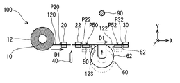
- First Embodiment> 1 to 10 are schematic plan views showing a tape winding apparatus 100 according to the first embodiment.
- the X axis and the Y axis extend in the horizontal direction
- the Z axis extends in the vertical direction.
- the positive direction (+ X direction) of the X axis coincides with the drawing direction D ⁇ b> 1 in which the tape is drawn out from the tape winding body 12.
- the positive direction (+ Y direction) of the Y axis is a direction from the tape drawing portion 120 side to the electric wire 90 side in the tape winding device 100.
- the positive direction (+ Z direction) of the Z axis corresponds to upward in the vertical direction.
- the tape winding apparatus 100 is an apparatus for winding a tape (adhesive tape) around an object (electric wire 90) extending in the vertical direction shown in FIG.
- extending in a certain specific direction includes not only the case of extending in parallel with the specific direction but also the case of extending in the combined direction of the specific direction and the direction perpendicular to the specific direction. Therefore, extending in the vertical direction includes not only the case of extending in the vertical direction (that is, extending in parallel to the direction of gravity) but also the case of extending in the combined direction of the vertical direction and the horizontal direction.
- the tape winding apparatus 100 includes a tape winding body support unit 10, a first holding unit 20, a second holding unit 22, a drawing holding unit 30, a cutting unit 40, a first receiving holding unit 50, and a second receiving holding. A part 52 and a tape winding part 60 are provided.
- the tape winding body support unit 10 rotatably supports a tape winding body 12 formed by winding a belt-like tape (adhesive tape such as a vinyl tape). Of the main surfaces on both sides of the tape, one main surface is an adhesive surface 10S and the other main surface is a non-adhesive surface 12S.
- the tape drawing portion 120 shown in FIG. 1 and the like is a portion drawn from the tape winding body 12 in the drawing direction D1 (+ X direction).
- the tape winding body 12 is a tape so that the adhesive surface 10S faces the + Y side and the non-adhesive surface 12S faces the -Y side. It is supported by the wound body support portion 10.
- maintains the tape extraction part 120 pulled out from the tape winding body 12 in the state which the adhesive surface 10S and non-adhesive surface 12S of both sides cross
- the first holding position P20 is a position in the drawing direction D1.
- the first holding unit 20 includes a pair of clamping members that are spaced apart from each other in the Y-axis direction, and a Y-axis moving mechanism that moves the pair of clamping members toward and away from each other in the Y-axis direction. ing.
- Each of the pair of holding members has, for example, a contact surface extending in the drawing direction D1 and wider than the width of the tape drawing portion 120, and contacts the tape drawing portion 120 at the contact surface.
- maintenance part 20 pinches the tape extraction
- This Y-axis moving mechanism is configured by a linear motor type or ball screw type drive unit or the like.
- the drawer holding unit 30 is a part that pulls out the tape from the tape winding body 12 in the drawing direction D1.
- the drawing holding unit 30 holds the tape drawing portion 120 at a first drawing position P30 that is separated from the first holding position P20 in the drawing direction D1.
- the drawer holding unit 30 is configured to be movable in the drawing direction D1, and is separated from the first drawing position P30 by a fixed distance from the first drawing position P30 in the drawing direction D1. A reciprocating movement with the second drawing position P32 is possible.
- the drawing holder 30 holds the tip of the tape drawing portion 120 at the first drawing position P30, and then moves to the second drawing position P32, thereby pulling out the tape drawing portion 120 from the tape winding body 12.
- the first drawing position P30 and the second drawing position P32 are positions in the drawing direction D1.
- the drawer holding unit 30 includes a pair of clamping members arranged at intervals in the Y-axis direction.
- the drawer holding unit 30 includes a Y-axis moving mechanism (not shown) that moves the pair of holding members in directions approaching and separating from each other in the Y-axis direction.
- the drawing holder 30 holds the tape drawing portion 120 from both sides in the thickness direction (Y-axis direction) by bringing the pair of holding members closer to each other.
- the drawer holding unit 30 includes an X-axis movement mechanism (not shown) that integrally moves the pair of clamping members in the X-axis direction.
- the Y-axis moving mechanism and the X-axis moving mechanism are configured by a linear motor type or ball screw type driving unit or the like.
- the second holding unit 22 holds the tape drawing portion 120 at the second holding position P22 between the first holding position P20 and the second drawing position P32.
- the second holding position P22 is a position in the drawing direction D1.
- the second holding unit 22 includes a Y-axis moving mechanism (not shown) that causes the pair of clamping members to approach each other.
- Each of the pair of clamping members has, for example, a contact surface extending in the drawing direction D1 and wider than the width of the tape drawing portion 120, and contacts the tape drawing portion 120 at the contact surface.
- the Y-axis moving mechanism is configured by a linear motor type or ball screw type drive unit or the like.
- the second holding unit 22 holds the tape drawing portion 120 from both sides in the thickness direction (Y-axis direction) by bringing the pair of holding members closer to each other.
- the pair of roller members of the second holding portion 22 are arranged on the + Y side or the ⁇ Y side from the tape drawing portion 120 so that the drawing holding portion 30 can linearly move from the second drawing position P32 to the first drawing position P30. Move to a separate retreat position.
- the moving distance of each of the pair of roller members of the second holding unit 22 from the retracted position to the holding position that holds the tape drawing portion 120 is at least longer than the length of the drawing holding unit 30 in the Y-axis direction.
- the cutting unit 40 cuts the tape drawing portion 120 at a cutting position P40 between the first holding position P20 and the second holding position P22 in the tape drawing portion 120.
- the cutting unit 40 includes a cutting blade and a Y-axis moving mechanism (not shown) that reciprocates the cutting blade in the Y-axis direction.
- the Y-axis moving mechanism is configured by a linear motor type or ball screw type drive unit or the like.
- the cutting blade of the cutting unit 40 is arranged on the non-adhesive surface 12S side ( ⁇ Y side) of the tape drawing portion 120, and cuts the tape drawing portion 120 by moving to + Y.
- a cutting tape portion 122 that is a portion separated from the tape winding body 12 is formed.
- the first receiving holding unit 50 and the second receiving holding unit 52 receive the cutting tape portion 122 held by the second holding unit 22 and the drawing holding unit 30, and the cutting tape.
- the portion 122 is transferred to the tape winding position.
- the first receiving holder 50 holds the cutting tape portion 122 at the first receiving position P50
- the second receiving holding portion 52 holds the cutting tape portion 122 at the second receiving position P52.
- the first receiving position P50 and the second receiving position P52 are sandwiched between the second holding position P22 and the second pulling position P32.
- the second receiving position P52 is a pulling direction D1 from the first receiving position P50. It is a position separated by a certain distance.
- the first receiving position P50 and the second receiving position P52 are positions in the drawing direction D1.
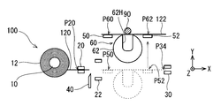
- the first receiving holder 50 moves from the first receiving position P50 to the first winding position P60, and the second receiving holder 52 moves from the second receiving position P52 to the second winding.
- Each of the first winding position P60 and the second winding position P62 is a direction that intersects the drawing direction D1 from each of the first receiving position P50 and the second receiving holding portion 52 (here, a horizontal direction orthogonal to the drawing direction D1). In the + Y direction) at a certain distance.
- the first receiving holder 50 and the second receiving holder 52 are constituted by chuck portions that hold the non-adhesive surface 12S by suction.
- One or more suction holes are formed on the surface facing the + Y side of the chuck portion, and the suction holes are made negative pressure by a suction device such as an air cylinder or a vacuum pump.
- a suction device such as an air cylinder or a vacuum pump.
- the non-adhesive surface 12S of the cutting tape portion 122 is adsorbed on the surface of the chuck portion facing the + Y side.
- the first receiving holder 50 and the second receiving holder 52 suck and hold the non-adhesive surface 12S, so that the cutting tape portion 122 can be received, held, and released (delivered) quickly. And it can be done with high accuracy.
- the first receiving holder 50 and the second receiving holder 52 include a Y-axis moving mechanism (not shown) that moves each chuck unit integrally in the Y-axis direction.
- This Y-axis moving mechanism is configured by a linear motor type or ball screw type drive unit or the like.
- the drawer holder 30 holds the cutting tape portion 122 together with the first receiver holder 50 and the second receiver holder 52 and pulls in the pull direction D1 from the second drawer position P32. It is possible to move to a third pulling position P34 separated by a distance.
- the tape winding part 60 includes the cutting tape portions 122 held by the first receiving holding part 50 and the second receiving holding part 52 arranged at the first winding position P60 and the second winding position P62, respectively. Wrap around the wire 90.
- the tape winding unit 60 for example, the configuration of a tape winding mechanism disclosed in Patent Document 1 can be used.
- the tape winding unit 60 includes a rotating body 62 and a pair of rotation driving units 64 and 64 that rotate the rotating body 62.
- the rotating body 62 is configured to have a concave portion 62H that is recessed in a U-shape from a part of the outer periphery of the disk-shaped member that extends in the horizontal direction toward the center.
- a pair of rotation driving units 64, 64 are in contact with the outer periphery of the rotating body 62.
- Each of the pair of rotation driving units 64 and 64 is a disk-like member, and is configured to actively rotate by a motor (not shown) or the like. When the pair of rotation driving units 64 and 64 rotate, the rotating body 62 that contacts the outer peripheral surface rotates.
- the tape winding unit 60 includes a Y-axis moving mechanism (not shown) that integrally moves the rotating body 62 and the pair of rotation driving units 64 and 64 in the Y-axis direction.
- This Y-axis moving mechanism is configured by a linear motor type or ball screw type drive unit or the like.
- the rotating body 62 moves from the non-adhesive surface 12S side of the cutting tape portion 122 to the + Y side so as to enter between the first receiving holder 50 and the second receiving holder 52. And the rotary body 62 makes the cutting tape part 122 and the electric wire 90 approach into the recessed part 62H. Then, the rotating body 62 is rotated by the rotation of the pair of rotation driving units 64 and 64, whereby the cutting tape portion 122 is wound around the electric wire 90 in the recess 62H.
- the tape drawing portion 120 drawn from the tape winding body 12 is held by the first holding portion 20 arranged at the first holding position P20.
- the leading end portion of the tape lead-out portion 120 protrudes from the end portions of the pair of holding members of the first holding portion 20.
- the drawer holding unit 30 moves from the second drawing position P ⁇ b> 32 to the first drawing position P ⁇ b> 30 and holds the leading end of the tape drawing portion 120.
- maintenance part 20 cancels
- drawing moves to the 2nd drawing position P32 from the 1st drawing position P30 after that.
- the tape is pulled out from the tape winding body 12, and the tape drawing portion 120 is extended in the drawing direction D1.
- the first holding unit 20 and the second holding unit 22 hold the tape drawing portion 120 at each of the first holding position P20 and the second holding position P22 together with the drawing holding unit 30.
- disconnection part 40 moves to + Y side so that it may approach between the 1st holding
- the tape drawing portion 120 is cut at the cutting position P40 between P22.
- the cut tape portion 122 cut off from the tape winding body 12 is held by the second holding portion 22 and the drawing holding portion 30.
- Each of the first holding unit 20 and the second holding unit 22 holds the tape drawing portion 120 from both sides by a pair of holding members. As a result, when the cutting unit 40 cuts the tape drawing portion 120, it is possible to reduce the movement of the tape drawing portion 120, and the tape drawing portion 120 can be cut well.
- the first receiving holder 50 and the second receiving holder 52 move from the predetermined retracted position toward the cutting tape portion 122.
- the first receiving holder 50 and the second receiving holder 52 suck and hold the cutting tape portion 122 from the non-adhesive surface 12S side at each of the first receiving position P50 and the second receiving position P52.
- the rotating body 62 of the tape winding unit 60 may move toward the cutting tape portion 122 together with the first receiving holding unit 50 and the second receiving holding unit 52, but this is not essential. .
- the second holding unit 22 releases the holding of the cutting tape portion 122.
- the drawer holding portion 30 moves to the third drawer position P34 separated from the second drawer position P32 in the drawer direction D1.
- the cutting tape portion 122 moves in the pull-out direction D ⁇ b> 1 while sliding on the suction surfaces of the first receiving holder 50 and the second receiving holder 52.
- the adsorption force for adsorbing the cutting tape portion 122 of the first receiving holding portion 50 and the second receiving holding portion 52 is such that the non-adhesive surface 12S of the cutting tape portion 122 can be slidably moved on these adsorption surfaces. It is desirable.
- the length of the portion that protrudes from the second receiving holder 52 in the pull-out direction D1 is such that the protruding portion does not hang down due to its own weight. It is preferred that
- the pair of holding members of the drawer holding portion 30 releases the holding of the cutting tape portion 122, and the cutting tape portion 122 is held in the first receiving holding portion 50 and the second receiving holding portion. Delivered to part 52.
- each of the first receiving holder 50 and the second receiving holder 52 starts moving in the + Y direction so that the cutting tape portion 122 approaches the electric wire 90, and the first winding position P60 and the second winding. It moves to each attachment position P62. Accordingly, the cutting tape portion 122 held by the first receiving holding portion 50 and the second receiving holding portion 52 is transferred to a position where the cutting tape portion 122 can be wound around the electric wire 90 by the tape winding portion 60.
- the cutting tape portion 122 is transferred to a position where the adhesive surface 10 ⁇ / b> S of the cutting tape portion 122 contacts the electric wire 90.
- the rotating body 62 and the pair of rotation driving units 64 and 64 of the tape winding unit 60 also move in the + Y direction so as to approach the electric wire 90.
- the rotating body 62 moves in the + Y direction with the concave portion 62H facing the + Y side.
- the rotating body 62 is positioned between the first receiving holder 50 and the second receiving holder 52 (that is, with the first winding) with the concave portion 62H facing the + Y side.
- the position between the position P60 and the second winding position P62) is entered, and the cutting tape portion 122 and the electric wire 90 are entered into the recess 62H.
- a pair of rotation drive parts 64 and 64 rotate the rotary body 62, and thereby the cutting tape part 122 is wound around the electric wire 90 in the recess 62H.
- the tape drawing portion 120 held by the first holding portion 20 at the first holding position P20 and the second holding portion 22 at the second holding position P22 is disposed between them.
- the cutting part 40 cuts at the cutting position P40. Accordingly, the cut tape portion 122 cut from the tape winding body 12 in the tape drawing portion 120 is held by the second holding portion 22 and the drawing holding portion 30. Further, the cutting tape portion 122 is transferred to the first receiving holder 50 and the second receiving holder 52, transferred to a predetermined position, and wound around the electric wire 90.
- the cutting tape portion 122 is separated from the tape winding body 12 and wound around the electric wire 90 until the second holding portion 22 and the drawing holding portion 30 or the first receiving holding portion 50 and The second receiving holding unit 52 holds the two receiving portions 52 in the drawing direction D1. For this reason, since it can suppress that the cutting tape part 122 droops with its own weight, the tape winding part 60 can wind the cutting tape part 122 around the electric wire 90 suitably.
- the tape winding apparatus 100A includes a tape winding body support unit 10, a cutting unit 40, and a tape winding unit 60, and a first holding unit 20A, a second holding unit 22A, a drawing holding unit 30A, and a first receiving unit.
- a holding unit 50A and a second receiving holding unit 52A are provided.
- the first holding unit 20A, the second holding unit 22A, and the drawer holding unit 30A are configured by a pair of roller members arranged at a constant interval in the Y-axis direction.
- Each roller member is, for example, a member formed in a cylindrical shape that extends longer than the width of the tape extraction portion 120, and rotates around a rotation axis that is parallel to the width direction of the tape extraction portion 120 (here, the Z-axis direction).
- the pair of roller members of the second holding portion 22A are arranged in the Y-axis direction so that the drawing holding portion 30 can move linearly from the second drawing position P32 toward the first drawing position P30. It is configured to be movable.
- the pair of roller members of the first holding unit 20A may be both configured to passively rotate, or one or both may be configured to be actively rotated by being connected to a motor or the like.
- the pair of roller members of the second holding portion 22A may also be configured to both rotate passively, or one or both may be configured to be actively rotated by being connected to a motor or the like.
- At least one of the pair of roller members of the first holding unit 20A or the second holding unit 22A includes a brake unit so as not to rotate.
- the tape drawing portion 120 can be prevented from shifting by stopping the rotation of the roller member by the brake means, and the tape drawing portion 120 can be suitably cut.
- the roller member that comes into contact with the adhesive surface 10S includes the brake means, it is possible to effectively suppress the movement of the tape drawing portion 120 in combination with the adhesiveness of the adhesive surface 10S.
- the pair of roller members of the drawing holder 30A move from the first drawing position P30 to the second drawing position P32 with the tip of the tape drawing portion 120 sandwiched between them.
- the tape is pulled out from the tape winding body 12 and the tape drawing portion 120 is extended.
- at least one of the roller members is preferably provided with a brake means for controlling the rotation to be impossible.
- the drawing holding portion 30A can suitably hold the tip portion of the tape drawing portion 120.
- the tape drawing portion 120 can be firmly held together with the adhesiveness of the adhesive surface 10S.
- the drawing holding unit 30A delivers the cutting tape portion 122 to the first receiving holding unit 50A and the second receiving holding unit 52A, the drawing holding unit 30A moves in the drawing direction D1 while rotating. Thereby, the holding of the cutting tape portion 122 by the drawer holding portion 30A is released.
- Each of the first receiving holder 50A and the second receiving holder 52A includes one roller member arranged so as to adhere to the adhesive surface 10S of the tape drawing portion 120. Each roller member is movable in the Y-axis direction.
- the rotating body 62 of the tape winding portion 60 enters between the first receiving holding portion 50A and the second receiving holding portion 52A with the concave portion 62H facing the + Y side. .
- the cutting tape portion 122 is hooked on the edge portions on both sides of the electric wire 90 and the concave portion 62H, so that the cutting tape portion 122 is accommodated in the concave portion 62H and at the same time, both ends of the cutting tape portion 122 move inward.
- the roller members of the first receiving holder 50A and the second receiving holder 52A rotate in opposite directions. Thereby, when the tape winding part 60 winds the cutting tape part 122 around the electric wire 90, the cutting tape part 122 can be held without hindering the movement of both ends of the cutting tape part 122.
- the apparatus configuration can be simplified and the cost can be reduced as compared with the case where it is performed.
Landscapes
- Engineering & Computer Science (AREA)
- Manufacturing & Machinery (AREA)
- Adhesive Tape Dispensing Devices (AREA)
- Manufacturing Of Electric Cables (AREA)
- Electric Cable Installation (AREA)
Abstract
鉛直方向に延びる対象物にテープを好適に巻付ける技術を提供する。テープ引出部分120を切断部40が切断することで、テープ巻回体から切り離された切断テープ部分122が、第2保持部22及び引出用保持部30に保持される。切断テープ部分122は、第1受取用保持部50及び第2受取用保持部52に渡されて、電線90付近に移送されて電線90に巻付けられる。切断テープ部分122は、テープ巻回体12から切り離されてから電線90に巻付けられるまでの間、第2保持部22及び引出用保持部30、あるいは、第1受取用保持部50及び第2受取用保持部52によって、引出方向D1に離れた2つの箇所で保持される。これによって、切断テープ部分122が自重で垂れることを抑制できるため、切断テープ部分122を電線90に好適に巻付けることができる。
Description
この発明は、対象物にテープを巻付ける技術に関する。
特許文献1には、電線にテープを巻き付けるテープ巻付装置が開示されている。このテープ巻付装置は、U字状に切りかかれた板状に形性された回転板と、その回転板を回転させる機構とを備える。回転板の切欠きに電線が配された状態で、その電線にテープの先端部が接着され、その状態で回転板が電線周りに回転することによって、電線にテープが巻付けられる。
ところで、車両などに搭載されるワイヤーハーネスを製造する際、コネクタが取り付けられた電線同士を仮結束して仮結を製造する場合がある。この仮結製造工程では、例えば図13が示すように、複数の電線90の端部が、布線バー92に保持されることで、重力方向に垂れ下がることで、鉛直方向に延びる状態で支持される場合がある。そして、この鉛直方向に延びる電線90の一部900にテープの巻付けを行う場合がある。
従来のテープ巻付装置を、このような鉛直方向に延びる電線90に適用した場合、テープ巻回体から引き出されたテープ引出部分が自重で垂れることによって、巻付け位置にばらつきが生じるおそれがあった。このため、テープの巻付け精度が悪化するおそれがあった。
本発明は、鉛直方向に延びる対象物にテープを好適に巻付ける技術を提供することを目的とする。
第1態様は、鉛直方向に延びる対象物にテープを巻付けるテープ巻付装置であって、両側の主面のうち、一方が粘着面であり他方が非粘着面であるテープが巻回されたテープ巻回体を回転可能に支持するテープ巻回体支持部と、前記テープ巻回体から、前記両側の主面が水平方向に交差する状態で引き出されたテープ引出部分を、第1保持位置で保持可能な第1保持部と、前記テープ引出部分を保持可能であり、かつ、前記第1保持位置から、前記テープ巻回体から前記テープを引き出す引出方向に隔てた第1引出位置と、当該第1引出位置から前記引出方向に隔てた第2引出位置との間で移動可能な引出用保持部と、前記第1保持位置及び前記第2引出位置の間の第2保持位置で前記テープ引出部分を保持可能な第2保持部と、前記第1保持位置及び前記第2保持位置の間の切断位置で前記テープ引出部分を切断可能な切断部と、前記テープ引出部分のうち前記切断部によって前記テープ巻回体から切り離された部分であって、前記第2保持部及び前記引出用保持部に保持された切断テープ部分を保持可能であり、前記第2保持位置及び前記第2引出位置の間の第1受取位置及び第2受取位置各々と、前記第1受取位置及び前記第2受取位置から前記引出方向に交差する方向に隔てた第1巻付位置及び第2巻付位置各々との間で移動可能な第1受取用保持部及び第2受取用保持部と、前記第1巻付位置及び前記第2巻付位置各々に配された前記第1受取用保持部及び第2受取用保持部が保持する前記テープ引出部分を対象物に巻付け可能なテープ巻付部とを備える。
第2態様は、第1態様のテープ巻付装置であって、前記第1保持部及び前記第2保持部が、前記テープ引出部分をその厚さ方向の両側から挟み持つ挟持部を含む。
第3態様は、第1態様又は第2態様のテープ巻付装置であって、前記第1受取用保持部及び前記第2受取用保持部各々が、前記テープ引出部分の前記非粘着面を吸着するチャック部を含む。
第4態様は、第1態様から第3態様のいずれか1つのテープ巻付装置であって、前記引出用保持部は、前記第1受取用保持部及び前記第2受取用保持部とともに前記切断テープ部分を保持した状態で、前記第2引出位置から前記引出方向に隔てた第3引出位置へ移動可能とされている。
第5態様は、第1態様から第4態様のいずれか1つのテープ巻付装置であって、前記第1受取用保持部及び前記第2受取用保持部各々が、前記テープ引出部分における前記粘着面に接着可能な回転体を含む。
第6態様は、対象物にテープを巻付けるテープ巻付方法であって、(a)テープ巻回体から引き出された、両側の主面のうち一方が粘着面であり他方が非粘着面のテープ引出部分を、第1保持部が第1保持位置で保持する工程と、(b)引出用保持部が、前記(a)工程にて前記第1保持部に保持された前記テープ引出部分を、前記第1保持位置から、前記テープ巻回体から前記テープを引き出す引出方向に隔てた第1引出位置で保持する工程と、(c)前記(b)工程にて前記テープ引出部分を保持した前記引出用保持部を、前記第1引出位置から前記引出方向に隔てた第2引出位置へ移動させる工程と、(d)前記(c)工程にて前記第1保持部及び前記引出用保持部が保持している前記テープ引出部分を、第2保持部が前記第1保持位置及び前記第2引出位置の間の第2保持位置で保持する工程と、(e)前記(d)工程にて前記第1保持部及び前記第2保持部が保持している前記テープ引出部分を、前記第1保持位置及び前記第2保持位置の間の切断位置で切断する工程と、(f)前記テープ引出部分のうち前記(e)工程にて前記テープ巻回体から切り離された切断テープ部分を、第1受取用保持部及び第2受取用保持部が、前記第2保持位置及び前記第2引出位置の間の第1受取位置及び第2受取位置各々で保持する工程と、(g)前記(f)工程にて前記切断テープ部分を保持している前記第1受取用保持部及び前記第2受取用保持部を、前記第1受取位置及び前記第2受取位置各々から、前記引出方向に交差する方向に隔てた第1巻付位置及び前記第2巻付位置各々へ移動させる工程と、(h)前記(g)工程にて、前記第1巻付位置及び前記第2巻付位置各々へ移動した前記第1受取用保持部及び第2受取用保持部が保持する前記切断テープ部分を、テープ巻付部が対象物に巻付ける工程とを含む。
第1態様のテープ巻付装置によると、第1保持位置の第1保持部及び第2保持位置の第2保持部に保持されたテープ引出部分が、それらの間の切断位置で切断される。これによって、テープ引出部分のうちのテープ巻回体から切り離された切断テープ部分が、第2保持部及び引出用保持部によって保持される。さらに、第2保持部及び引出用保持部に保持された切断テープ部分が、第1受取用保持部及び第2受取用保持部に渡されて、所定の位置まで移送され、対象物に巻付けられる。したがって、切断テープ部分は、テープ巻回体から切り離されてから対象物に巻付けられるまでの間、第2保持部及び引出用保持部、あるいは、第1及び第2受取用保持部によって、引出方向に離れた2つの箇所で保持される。これによって、切断テープ部分が自重で垂れることを抑制できるため、テープ巻付部が切断テープ部分を対象物に好適に巻付けることができる。
第2態様のテープ巻付装置によると、第1保持部及び第2保持部各々が、テープ引出部分をその両側から挟持する。これによって、切断部がテープ引出部分を切断する際、テープ引出部分がずれ動くことを低減できる。したがって、テープ引出部分を良好に切断できる。
第3態様のテープ巻付装置によると、吸着を解除することで、切断テープ部分を容易に離して、テープ巻付部に渡すことができる。
第4態様のテープ巻付装置によると、切断テープ部分のうち、第2保持部に保持されていた部分を、第1受取用保持部側に移動させることで、その部分が自重で垂れることを抑制できる。
第5態様のテープ巻付装置によると、テープ引出部分の粘着面に第1及び第2受取用保持部の回転体を接着させることで、テープ引出部分を保持できる。このため、第1及び第2受取用保持部の構成を簡略化できる。また、回転体が回転することで、切断テープ部分の保持を解除できる。
第6態様のテープ巻付方法によると、切断テープ部分は、テープ巻回体から切り離されてから対象物に巻付けられるまでの間、第2保持部及び引出用保持部、あるいは、第1及び第2受取用保持部によって、引出方向に離れた2つの箇所で保持される。これによって、切断テープ部分が自重で垂れることを抑制できるため、テープ巻付部が切断テープ部分を対象物に好適に巻付けることができる。
以下、添付の図面を参照しながら、本発明の実施形態について説明する。なお、この実施形態に記載されている構成要素はあくまでも例示であり、本発明の範囲をそれらのみに限定する趣旨のものではない。また、図面においては、理解容易のため、必要に応じて各部の寸法や数が誇張または簡略化して図示されている場合がある。
<1. 第1実施形態>
図1~図10は、第1実施形態のテープ巻付装置100を示す概略平面図である。各図には、各要素の位置関係を説明するために、右手系のXYZ直交座標が付されている。このXYZ直交座標系において、X軸及びY軸は水平方向に延びており、Z軸は鉛直方向に延びる。ここで、X軸の正方向(+X方向)は、テープ巻回体12からテープを引き出す引出方向D1に一致している。また、Y軸の正方向(+Y方向)は、テープ巻付装置100におけるテープ引出部分120側から電線90側に向かう方向である。Z軸の正方向(+Z方向)は、鉛直方向上向きに対応する。
図1~図10は、第1実施形態のテープ巻付装置100を示す概略平面図である。各図には、各要素の位置関係を説明するために、右手系のXYZ直交座標が付されている。このXYZ直交座標系において、X軸及びY軸は水平方向に延びており、Z軸は鉛直方向に延びる。ここで、X軸の正方向(+X方向)は、テープ巻回体12からテープを引き出す引出方向D1に一致している。また、Y軸の正方向(+Y方向)は、テープ巻付装置100におけるテープ引出部分120側から電線90側に向かう方向である。Z軸の正方向(+Z方向)は、鉛直方向上向きに対応する。
テープ巻付装置100は、図13が示す鉛直方向に延びる対象物(電線90)にテープ(粘着テープ)を巻付ける装置である。なお、本願において、ある特定方向に延びるとは、その特定方向に平行に延びる場合のみならず、その特定方向及びその特定方向に垂直な方向の合成方向に延びる場合も含む。したがって、鉛直方向に延びるとは、必ずしも鉛直方向に沿って延びる(すなわち、重力方向に平行に延びる)場合のみならず、鉛直方向と水平方向の合成方向に延びる場合も含む。
テープ巻付装置100は、テープ巻回体支持部10、第1保持部20、第2保持部22、引出用保持部30、切断部40、第1受取用保持部50、第2受取用保持部52及びテープ巻付部60を備える。
<テープ巻回体支持部10>
テープ巻回体支持部10は、帯状のテープ(ビニールテープなどの粘着テープ)が巻回されることによって構成されたテープ巻回体12を回転可能に支持する。このテープの両側の主面のうち、一方主面は粘着面10Sであり、他方主面は非粘着面12Sである。図1などが示すテープ引出部分120は、テープ巻回体12から引出方向D1(+X方向)に引き出された部分である。テープ巻回体12から引き出されたテープ引出部分120の両側の主面のうち、粘着面10Sが+Y側を向き、非粘着面12Sが-Y側を向くように、テープ巻回体12がテープ巻回体支持部10に支持されている。
テープ巻回体支持部10は、帯状のテープ(ビニールテープなどの粘着テープ)が巻回されることによって構成されたテープ巻回体12を回転可能に支持する。このテープの両側の主面のうち、一方主面は粘着面10Sであり、他方主面は非粘着面12Sである。図1などが示すテープ引出部分120は、テープ巻回体12から引出方向D1(+X方向)に引き出された部分である。テープ巻回体12から引き出されたテープ引出部分120の両側の主面のうち、粘着面10Sが+Y側を向き、非粘着面12Sが-Y側を向くように、テープ巻回体12がテープ巻回体支持部10に支持されている。
<第1保持部20>
第1保持部20は、テープ巻回体12から、両側の粘着面10S及び非粘着面12Sが水平方向に交差する(ここでは直交する)状態で引き出されたテープ引出部分120を、第1保持位置P20で保持する。第1保持位置P20は、引出方向D1における位置である。第1保持部20は、Y軸方向に間隔を隔てて配された一対の挟持部材と、その一対の挟持部材をY軸方向において接近及び離隔する方向に移動させるY軸移動機構とで構成されている。一対の挟持部材各々は、例えば引出方向D1に延びるとともにテープ引出部分120の幅よりも広い当接面を有しており、その当接面でテープ引出部分120に当接する。第1保持部20は、一対の挟持部材を互いに接近させることによって、テープ引出部分120をその厚さ方向(Y軸方向)の両側から挟み持つ。このY軸移動機構は、リニアモータ式又はボールネジ式の駆動部などで構成される。
第1保持部20は、テープ巻回体12から、両側の粘着面10S及び非粘着面12Sが水平方向に交差する(ここでは直交する)状態で引き出されたテープ引出部分120を、第1保持位置P20で保持する。第1保持位置P20は、引出方向D1における位置である。第1保持部20は、Y軸方向に間隔を隔てて配された一対の挟持部材と、その一対の挟持部材をY軸方向において接近及び離隔する方向に移動させるY軸移動機構とで構成されている。一対の挟持部材各々は、例えば引出方向D1に延びるとともにテープ引出部分120の幅よりも広い当接面を有しており、その当接面でテープ引出部分120に当接する。第1保持部20は、一対の挟持部材を互いに接近させることによって、テープ引出部分120をその厚さ方向(Y軸方向)の両側から挟み持つ。このY軸移動機構は、リニアモータ式又はボールネジ式の駆動部などで構成される。
<引出用保持部30>
引出用保持部30は、テープ巻回体12からテープを引出方向D1に引き出す部分である。引出用保持部30は、図2が示すように、第1保持位置P20から引出方向D1に隔てた第1引出位置P30でテープ引出部分120を保持する。また、引出用保持部30は、図3が示すように、引出方向D1へ移動可能に構成されており、第1引出位置P30と、第1引出位置P30から引出方向D1に一定距離だけ隔てた第2引出位置P32との間で往復移動可能とされている。引出用保持部30は、第1引出位置P30でテープ引出部分120の先端部を保持した後、第2引出位置P32に移動することで、テープ巻回体12からテープ引出部分120を引き出す。第1引出位置P30及び第2引出位置P32は、引出方向D1における位置である。
引出用保持部30は、テープ巻回体12からテープを引出方向D1に引き出す部分である。引出用保持部30は、図2が示すように、第1保持位置P20から引出方向D1に隔てた第1引出位置P30でテープ引出部分120を保持する。また、引出用保持部30は、図3が示すように、引出方向D1へ移動可能に構成されており、第1引出位置P30と、第1引出位置P30から引出方向D1に一定距離だけ隔てた第2引出位置P32との間で往復移動可能とされている。引出用保持部30は、第1引出位置P30でテープ引出部分120の先端部を保持した後、第2引出位置P32に移動することで、テープ巻回体12からテープ引出部分120を引き出す。第1引出位置P30及び第2引出位置P32は、引出方向D1における位置である。
引出用保持部30は、Y軸方向に間隔を隔てて配された一対の挟持部材を備える。また、引出用保持部30は、その一対の挟持部材をY軸方向において接近及び離隔する方向に移動させるY軸移動機構(不図示)を備える。引出用保持部30は、一対の挟持部材を互いに接近させることによって、テープ引出部分120をその厚さ方向(Y軸方向)の両側から挟み持つ。さらに、引出用保持部30は、一対の挟持部材を一体的にX軸方向に移動させるX軸移動機構(不図示)を備える。Y軸移動機構及びX軸移動機構は、リニアモータ式又はボールネジ式の駆動部などで構成される。
<第2保持部22>
第2保持部22は、図4が示すように、第1保持位置P20及び第2引出位置P32の間の第2保持位置P22でテープ引出部分120を保持する。第2保持位置P22は、引出方向D1における位置である。第2保持部22は、一対の挟持部材を互いに接近させるY軸移動機構(不図示)を備える。一対の挟持部材の各々は、例えば引出方向D1に延びるとともにテープ引出部分120の幅よりも広い当接面を有しており、その当接面でテープ引出部分120に当接する。Y軸移動機構は、リニアモータ式又はボールネジ式の駆動部などで構成される。第2保持部22は、一対の挟持部材を互いに接近させることによって、テープ引出部分120をその厚さ方向(Y軸方向)の両側から挟み持つ。
第2保持部22は、図4が示すように、第1保持位置P20及び第2引出位置P32の間の第2保持位置P22でテープ引出部分120を保持する。第2保持位置P22は、引出方向D1における位置である。第2保持部22は、一対の挟持部材を互いに接近させるY軸移動機構(不図示)を備える。一対の挟持部材の各々は、例えば引出方向D1に延びるとともにテープ引出部分120の幅よりも広い当接面を有しており、その当接面でテープ引出部分120に当接する。Y軸移動機構は、リニアモータ式又はボールネジ式の駆動部などで構成される。第2保持部22は、一対の挟持部材を互いに接近させることによって、テープ引出部分120をその厚さ方向(Y軸方向)の両側から挟み持つ。
第2保持部22の一対のローラ部材は、引出用保持部30が第2引出位置P32から第1引出位置P30に直線移動できるようにするため、テープ引出部分120から+Y側又は-Y側のそれぞれに離れた待避位置に移動する。第2保持部22の一対のローラ部材各々の、待避位置からテープ引出部分120を挟み持つ挟持位置までの移動距離は、少なくとも引出用保持部30のY軸方向の長さよりも大きくなっている。
<切断部40>
切断部40は、図5が示すように、テープ引出部分120における第1保持位置P20及び第2保持位置P22の間の切断位置P40で、テープ引出部分120を切断する。切断部40は、切断刃とその切断刃をY軸方向に往復移動させるY軸移動機構(不図示)を備える。Y軸移動機構は、リニアモータ式又はボールネジ式の駆動部などで構成される。ここでは、切断部40の切断刃はテープ引出部分120の非粘着面12S側(-Y側)に配されており、+Yに移動することで、テープ引出部分120を切断する。これによって、テープ巻回体12から切り離された部分である切断テープ部分122が形成される。
切断部40は、図5が示すように、テープ引出部分120における第1保持位置P20及び第2保持位置P22の間の切断位置P40で、テープ引出部分120を切断する。切断部40は、切断刃とその切断刃をY軸方向に往復移動させるY軸移動機構(不図示)を備える。Y軸移動機構は、リニアモータ式又はボールネジ式の駆動部などで構成される。ここでは、切断部40の切断刃はテープ引出部分120の非粘着面12S側(-Y側)に配されており、+Yに移動することで、テープ引出部分120を切断する。これによって、テープ巻回体12から切り離された部分である切断テープ部分122が形成される。
<第1受取用保持部50、第2受取用保持部52>
第1受取用保持部50及び第2受取用保持部52は、図6が示すように、第2保持部22及び引出用保持部30にて保持された切断テープ部分122を受け取り、その切断テープ部分122をテープ巻付ける位置まで移送する。
第1受取用保持部50及び第2受取用保持部52は、図6が示すように、第2保持部22及び引出用保持部30にて保持された切断テープ部分122を受け取り、その切断テープ部分122をテープ巻付ける位置まで移送する。
第1受取用保持部50は第1受取位置P50で切断テープ部分122を保持し、第2受取用保持部52は第2受取位置P52で切断テープ部分122を保持する。第1受取位置P50及び第2受取位置P52は、第2保持位置P22及び第2引出位置P32の間に挟まれる位置であって、第2受取位置P52は、第1受取位置P50から引出方向D1に一定距離だけ隔てた位置である。第1受取位置P50及び第2受取位置P52は、引出方向D1における位置である。
また、図7が示すように、第1受取用保持部50は第1受取位置P50から第1巻付位置P60に移動し、第2受取用保持部52は第2受取位置P52から第2巻付位置P62に移動する。第1巻付位置P60及び第2巻付位置P62各々は、第1受取位置P50及び第2受取用保持部52各々から引出方向D1に交差する方向(ここでは、引出方向D1に直交する水平方向である+Y方向)に一定距離だけ隔てた位置である。
第1受取用保持部50及び第2受取用保持部52は、非粘着面12Sを吸着保持するチャック部で構成されている。チャック部の+Y側を向く表面には、1つ以上の吸着孔(不図示)が形成され、当該吸着孔がエアシリンダ又は真空ポンプなどの吸引装置で負圧にされる。これによって、チャック部の+Y側を向く表面に、切断テープ部分122の非粘着面12Sが吸着される。このように、第1受取用保持部50及び第2受取用保持部52が非粘着面12Sを吸着保持するようにすることで、切断テープ部分122の受取り、保持及び保持解除(引渡し)を迅速かつ高精度に行える。
第1受取用保持部50及び第2受取用保持部52は、各々のチャック部を一体的にY軸方向に移動させるY軸移動機構(不図示)を備える。このY軸移動機構は、リニアモータ式又はボールネジ式の駆動部などで構成される。
上記引出用保持部30は、図8が示すように、第1受取用保持部50及び第2受取用保持部52とともに切断テープ部分122を保持した状態で、第2引出位置P32から引出方向D1に隔てた第3引出位置P34へ移動可能とされている。
<テープ巻付部60>
テープ巻付部60は、第1巻付位置P60及び第2巻付位置P62各々に配された第1受取用保持部50及び第2受取用保持部52に保持されている切断テープ部分122を、電線90に巻付ける。
テープ巻付部60は、第1巻付位置P60及び第2巻付位置P62各々に配された第1受取用保持部50及び第2受取用保持部52に保持されている切断テープ部分122を、電線90に巻付ける。
テープ巻付部60としては、例えば特許文献1に開示されたテープ巻付機構の構成を利用できる。テープ巻付部60は、回転体62と、回転体62を回転させる一対の回転駆動部64,64を含む。回転体62は、水平方向に広がる円板状部材の外周の一部から中心に向けてU字状に凹む凹部62Hを形成した構成とされている。回転体62の外周には、一対の回転駆動部64、64が当接している。一対の回転駆動部64,64各々は、円板状部材であり、不図示のモータなどによって能動的に回転するように構成されている。一対の回転駆動部64,64が回転すると、その外周面に当接する回転体62が回転する。
図9及び図10が示すように、テープ巻付部60は、回転体62及び一対の回転駆動部64,64を一体的にY軸方向に移動させるY軸移動機構(不図示)を備える。このY軸移動機構は、リニアモータ式又はボールネジ式の駆動部などで構成される。
回転体62は、切断テープ部分122の非粘着面12S側から、第1受取用保持部50,第2受取用保持部52の間に進入するように+Y側に移動する。そして、回転体62は、その凹部62H内に切断テープ部分122及び電線90を進入させる。そして、一対の回転駆動部64,64が回転することで回転体62が回転し、これによって、凹部62H内にて電線90に切断テープ部分122が巻付けられる。
<動作>
次に、鉛直方向に延びる90に対して、テープ巻付装置100がテープ(切断テープ部分122)を巻付ける動作の手順について説明する。
次に、鉛直方向に延びる90に対して、テープ巻付装置100がテープ(切断テープ部分122)を巻付ける動作の手順について説明する。
まず、図1が示すように、テープ巻回体12から引き出されたテープ引出部分120が、第1保持位置P20に配された第1保持部20によって保持されている。テープ引出部分120の先端部は、第1保持部20の一対の挟持部材の端部からはみ出た状態とされている。
続いて、図2が示すように、引出用保持部30が第2引出位置P32から第1引出位置P30に移動して、テープ引出部分120の先端部を保持する。そして、図3が示すように、第1保持部20がテープ引出部分120の保持を解除し、その後、引出用保持部30が第1引出位置P30から第2引出位置P32へ移動する。これによって、テープ巻回体12からテープが引き出され、テープ引出部分120が引出方向D1に延長される。
続いて、図4が示すように、引出用保持部30とともに、第1保持部20及び第2保持部22が、第1保持位置P20及び第2保持位置P22の各々でテープ引出部分120を保持する。そして、図5が示すように、切断部40が、第1保持部20及び第2保持部22の間に進入するように+Y側へ移動することで、第1保持位置P20及び第2保持位置P22の間の切断位置P40にてテープ引出部分120を切断する。これによって、テープ巻回体12から切り離された切断テープ部分122が、第2保持部22及び引出用保持部30に保持された状態となる。第1保持部20及び第2保持部22各々は、一対の挟持部材によって、テープ引出部分120を両側から挟み持つ。これによって、切断部40がテープ引出部分120を切断する際、テープ引出部分120がずれ動くことを低減できるため、テープ引出部分120を良好に切断できる。
続いて、図6が示すように、第1受取用保持部50及び第2受取用保持部52が所定の待避位置から切断テープ部分122に向けて移動する。そして、第1受取用保持部50及び第2受取用保持部52が、第1受取位置P50及び第2受取位置P52各々にて、切断テープ部分122をその非粘着面12S側から吸着保持する。このとき、テープ巻付部60の回転体62も、第1受取用保持部50及び第2受取用保持部52とともに、切断テープ部分122に向けて移動してもよいが、これは必須ではない。
続いて、図7が示すように、第2保持部22が切断テープ部分122の保持を解除する。その後、図8が示すように、引出用保持部30が第2引出位置P32から引出方向D1に隔てた第3引出位置P34に移動する。これによって、切断テープ部分122が、第1受取用保持部50及び第2受取用保持部52の吸着面上を摺接しつつ、引出方向D1へ移動する。第1受取用保持部50及び第2受取用保持部52の切断テープ部分122を吸着する吸着力は、切断テープ部分122の非粘着面12Sがこれらの吸着面上を摺接移動できる程度とされることが望ましい。このように、切断テープ部分122を引出方向D1へ移動させることによって、切断テープ部分122のうち第2保持部22に保持されていた部分を、第1受取用保持部50に接近させることができるため、その部分が自重で垂れることを低減できる。
なお、引出方向D1への移動後の切断テープ部分122のうち、第2受取用保持部52から引出方向D1へはみ出た部分の長さは、そのはみ出た部分が自重で垂れない程度の長さとされることが好ましい。
続いて、図9が示すように、引出用保持部30の一対の挟持部材が切断テープ部分122の保持を解除して、切断テープ部分122を第1受取用保持部50及び第2受取用保持部52に引渡す。そして、第1受取用保持部50及び第2受取用保持部52各々が、切断テープ部分122を電線90に接近するように+Y方向へ移動を開始し、第1巻付位置P60及び第2巻付位置P62各々までに移動する。これによって、第1受取用保持部50及び第2受取用保持部52に保持された切断テープ部分122が、切断テープ部分122がテープ巻付部60によって電線90に巻付け可能な位置まで移送される。ここでは、切断テープ部分122の粘着面10Sが電線90に接触する位置まで切断テープ部分122が移送される。このとき、テープ巻付部60の回転体62及び一対の回転駆動部64,64も、電線90に接近するように、+Y方向へ移動する。その際、回転体62は、その凹部62Hを+Y側へ向けた状態で、+Y方向へ移動する。
続いて、図10が示すように、回転体62が、その凹部62Hを+Y側に向けた状態で第1受取用保持部50及び第2受取用保持部52の間(すなわち、第1巻付位置P60及び第2巻付位置P62の間の位置)に進入し、その凹部62Hに切断テープ部分122及び電線90を進入させる。そして、一対の回転駆動部64,64が回転体62を回転させることによって、凹部62H内にて電線90に切断テープ部分122を巻付ける。巻付動作が完了すると、テープ巻付装置100の各要素は、図1に示す初期の位置へ復帰する。
<効果>
以上のように、テープ巻付装置100によると、第1保持位置P20の第1保持部20及び第2保持位置P22の第2保持部22に保持されたテープ引出部分120を、それらの間の切断位置P40にて切断部40が切断する。これによって、テープ引出部分120のうちテープ巻回体12から切り離された切断テープ部分122が、第2保持部22及び引出用保持部30によって保持される。さらに、この切断テープ部分122は、第1受取用保持部50及び第2受取用保持部52に渡されて、所定の位置まで移送され、電線90に巻付けられる。したがって、切断テープ部分122は、テープ巻回体12から切り離されてから電線90に巻付けられるまでの間、第2保持部22及び引出用保持部30、あるいは、第1受取用保持部50及び第2受取用保持部52によって、引出方向D1に離れた2つの箇所で保持される。このため、切断テープ部分122が自重で垂れることを抑制できるため、切断テープ部分122をテープ巻付部60が電線90に好適に巻付けることができる。
以上のように、テープ巻付装置100によると、第1保持位置P20の第1保持部20及び第2保持位置P22の第2保持部22に保持されたテープ引出部分120を、それらの間の切断位置P40にて切断部40が切断する。これによって、テープ引出部分120のうちテープ巻回体12から切り離された切断テープ部分122が、第2保持部22及び引出用保持部30によって保持される。さらに、この切断テープ部分122は、第1受取用保持部50及び第2受取用保持部52に渡されて、所定の位置まで移送され、電線90に巻付けられる。したがって、切断テープ部分122は、テープ巻回体12から切り離されてから電線90に巻付けられるまでの間、第2保持部22及び引出用保持部30、あるいは、第1受取用保持部50及び第2受取用保持部52によって、引出方向D1に離れた2つの箇所で保持される。このため、切断テープ部分122が自重で垂れることを抑制できるため、切断テープ部分122をテープ巻付部60が電線90に好適に巻付けることができる。
<2. 第2実施形態>
次に、第2実施形態について説明する。なお、以降の説明において、既に説明した要素と同様の機能を有する要素については、同じ符号またはアルファベット文字を追加した符号を付して、詳細な説明を省略する場合がある。
次に、第2実施形態について説明する。なお、以降の説明において、既に説明した要素と同様の機能を有する要素については、同じ符号またはアルファベット文字を追加した符号を付して、詳細な説明を省略する場合がある。
図11及び図12は、第2実施形態のテープ巻付装置100Aを示す概略平面図である。テープ巻付装置100Aは、テープ巻回体支持部10、切断部40及びテープ巻付部60を備えるとともに、第1保持部20A、第2保持部22A、引出用保持部30A、第1受取用保持部50A及び第2受取用保持部52Aを備える。
第1保持部20A、第2保持部22A及び引出用保持部30Aは、Y軸方向に一定間隔を隔てて配された一対のローラ部材で構成されている。各ローラ部材は、例えばテープ引出部分120の幅よりも長く延びる円筒状に形成された部材であり、テープ引出部分120の幅方向(ここではZ軸方向)に平行な回転軸周りに回転する。
第1保持部20Aは、他の保持部よりもテープ巻回体12に近い位置に配されており、第1保持位置P20にて一対のローラ部材でテープ引出部分120をY軸方向の両側から挟み持つ。引出用保持部30がテープ引出部分120の先端を引くことで、テープ引出部分120が延長される際、第1保持部20Aの一対のローラ部材はそのテープ引出部分120の移動に合わせて回転する。このため、第1保持部20Aの一対のローラ部材は、第1保持部20の一対の挟持部材のようにY軸方向に沿って移動可能に構成されていることは必須ではない(図3参照)。
第2保持部22Aの一対のローラ部材は、引出用保持部30が第2引出位置P32から第1引出位置P30に向けて直線移動可能とするため、互いに接近あるいは離隔するようにY軸方向に移動可能に構成される。
第1保持部20Aの一対のローラ部材は、双方ともに受動回転するように構成されてもよいし、一方又は双方がモータなどに接続されて能動回転するように構成されていてもよい。第2保持部22Aの一対のローラ部材についても、双方ともに受動回転するように構成されてもよいし、一方又は双方がモータなどに接続されて能動回転するように構成されていてもよい。
なお、第1保持部20A又は第2保持部22Aの一対のローラ部材のうち、少なくとも一方のローラ部材は、回転しないようにブレーキ手段を備えていることが好ましい。より例えば、切断部40によってテープ引出部分120を切断する際、ブレーキ手段によってローラ部材の回転を停止させることで、テープ引出部分120がずれ動くことを抑制でき、テープ引出部分120を好適に切断できる。特に、粘着面10Sに当接するローラ部材が上記ブレーキ手段を備えることで、その粘着面10Sの粘着性とあいまって、テープ引出部分120のずれ動くことを効果的に抑制できる。
引出用保持部30Aの一対のローラ部材は、テープ引出部分120の先端部を挟み持った状態で、第1引出位置P30から第2引出位置P32まで移動する。これによって、テープ巻回体12からテープを引き出して、テープ引出部分120を延長する。引出用保持部30Aの一対のローラ部材のうち、少なくとも一方のローラ部材は、回転不能に制御するブレーキ手段を備えることが好ましい。ブレーキ手段を備えることによって、引出用保持部30Aがテープ引出部分120の先端部を好適に保持できる。特に、粘着面10Sに当接するローラ部材が上記ブレーキ手段を備えることで、その粘着面10Sの粘着性とあいまって、テープ引出部分120を強固に保持できる。
引出用保持部30Aが、切断テープ部分122を第1受取用保持部50A及び第2受取用保持部52Aに引渡す場合、回転しながら引出方向D1に向けて移動する。これによって、引出用保持部30Aによる、切断テープ部分122の保持が解除される。
第1受取用保持部50A及び第2受取用保持部52A各々は、テープ引出部分120の粘着面10Sに接着するように配置されたローラ部材を1つずつ備えている。各ローラ部材は、Y軸方向に移動可能とされている。第1受取用保持部50Aが第1受取位置P50Aから第1巻付位置P60Aに移動し、第2受取用保持部52Aが第2受取位置P52Aから第2巻付位置P62Aへ移動することによって、切断テープ部分122がテープ巻付部60によって電線90に巻付け可能な位置まで移送される。
図12が示すように、テープ巻付部60の回転体62が、その凹部62Hを+Y側に向けた状態で、第1受取用保持部50A及び第2受取用保持部52Aの間に進入する。すると、切断テープ部分122が電線90及び凹部62Hの両側の縁部に引っかかることで、切断テープ部分122が凹部62Hに収容されると同時に、切断テープ部分122の両端部が内側に向けて移動する。このとき、第1受取用保持部50A及び第2受取用保持部52Aのローラ部材各々が互いに逆向きに回転する。これによって、テープ巻付部60が切断テープ部分122を電線90に巻付ける際、切断テープ部分122の両端側の移動を妨げずに、かつ、切断テープ部分122を保持することができる。
このように、ローラ部材を備える第1受取用保持部50A及び第2受取用保持部52Aを採用することによって、チャック部を備える第1受取用保持部50及び第2受取用保持部52を採用する場合よりも装置構成の簡易化及び低コスト化を図ることができる。
この発明は詳細に説明されたが、上記の説明は、すべての局面において、例示であって、この発明がそれに限定されるものではない。例示されていない無数の変形例が、この発明の範囲から外れることなく想定され得るものと解される。また、上記各実施形態及び各変形例で説明した各構成は、相互に矛盾しない限り適宜組み合わせたり、省略したりすることができる。
10 テープ巻回体支持部
12 テープ巻回体
10S 粘着面
12S 非粘着面
120 テープ引出部分
122 切断テープ部分
20,20A 第1保持部
22,22A 第2保持部
30,30A 引出用保持部
40 切断部
50,50A 第1受取用保持部
52,52A 第2受取用保持部
60 テープ巻付部
62 回転体
62H 凹部
64 回転駆動部
90 電線(対象物)
100,100A テープ巻付装置
D1 引出方向
P20 第1保持位置
P22 第2保持位置
P30 第1引出位置
P32 第2引出位置
P34 第3引出位置
P40 切断位置
P50,P50A 第1受取位置
P52,P52A 第2受取位置
P60,P60A 第1巻付位置
P62,P62A 第2巻付位置
Claims (6)
- 鉛直方向に延びる対象物にテープを巻付けるテープ巻付装置であって、
両側の主面のうち、一方が粘着面であり他方が非粘着面であるテープが巻回されたテープ巻回体を回転可能に支持するテープ巻回体支持部と、
前記テープ巻回体から、前記両側の主面が水平方向に交差する状態で引き出されたテープ引出部分を、第1保持位置で保持可能な第1保持部と、
前記テープ引出部分を保持可能であり、かつ、前記第1保持位置から、前記テープ巻回体から前記テープを引き出す引出方向に隔てた第1引出位置と、当該第1引出位置から前記引出方向に隔てた第2引出位置との間で移動可能な引出用保持部と、
前記第1保持位置及び前記第2引出位置の間の第2保持位置で前記テープ引出部分を保持可能な第2保持部と、
前記第1保持位置及び前記第2保持位置の間の切断位置で前記テープ引出部分を切断可能な切断部と、
前記テープ引出部分のうち前記切断部によって前記テープ巻回体から切り離された部分であって、前記第2保持部及び前記引出用保持部に保持された切断テープ部分を保持可能であり、前記第2保持位置及び前記第2引出位置の間の第1受取位置及び第2受取位置各々と、前記第1受取位置及び前記第2受取位置から前記引出方向に交差する方向に隔てた第1巻付位置及び第2巻付位置各々との間で移動可能な第1受取用保持部及び第2受取用保持部と、
前記第1巻付位置及び前記第2巻付位置各々に配された前記第1受取用保持部及び第2受取用保持部が保持する前記テープ引出部分を対象物に巻付け可能なテープ巻付部と、
を備える、テープ巻付装置。 - 請求項1のテープ巻付装置であって、
前記第1保持部及び前記第2保持部が、前記テープ引出部分をその厚さ方向の両側から挟み持つ挟持部を含む、テープ巻付装置。 - 請求項1又は請求項2のテープ巻付装置であって、
前記第1受取用保持部及び前記第2受取用保持部各々が、前記テープ引出部分の前記非粘着面を吸着するチャック部を含む、テープ巻付装置。 - 請求項1から請求項3のいずれか1項のテープ巻付装置であって、
前記引出用保持部は、前記第1受取用保持部及び前記第2受取用保持部とともに前記切断テープ部分を保持した状態で、前記第2引出位置から前記引出方向に隔てた第3引出位置へ移動可能とされている、テープ巻付装置。 - 請求項1から請求項4のいずれか1項のテープ巻付装置であって、
前記第1受取用保持部及び前記第2受取用保持部各々が、前記テープ引出部分における前記粘着面に接着可能な回転体を含む、テープ巻付装置。 - 対象物にテープを巻付けるテープ巻付方法であって、
(a) テープ巻回体から引き出された、両側の主面のうち一方が粘着面であり他方が非粘着面のテープ引出部分を、第1保持部が第1保持位置で保持する工程と、
(b) 引出用保持部が、前記(a)工程にて前記第1保持部に保持された前記テープ引出部分を、前記第1保持位置から、前記テープ巻回体から前記テープを引き出す引出方向に隔てた第1引出位置で保持する工程と、
(c) 前記(b)工程にて前記テープ引出部分を保持した前記引出用保持部を、前記第1引出位置から前記引出方向に隔てた第2引出位置へ移動させる工程と、
(d) 前記(c)工程にて前記第1保持部及び前記引出用保持部が保持している前記テープ引出部分を、第2保持部が前記第1保持位置及び前記第2引出位置の間の第2保持位置で保持する工程と、
(e) 前記(d)工程にて前記第1保持部及び前記第2保持部が保持している前記テープ引出部分を、前記第1保持位置及び前記第2保持位置の間の切断位置で切断する工程と、
(f) 前記テープ引出部分のうち前記(e)工程にて前記テープ巻回体から切り離された切断テープ部分を、第1受取用保持部及び第2受取用保持部が、前記第2保持位置及び前記第2引出位置の間の第1受取位置及び第2受取位置各々で保持する工程と、
(g) 前記(f)工程にて前記切断テープ部分を保持している前記第1受取用保持部及び前記第2受取用保持部を、前記第1受取位置及び前記第2受取位置各々から、前記引出方向に交差する方向に隔てた第1巻付位置及び前記第2巻付位置各々へ移動させる工程と、
(h) 前記(g)工程にて、前記第1巻付位置及び前記第2巻付位置各々へ移動した前記第1受取用保持部及び第2受取用保持部が保持する前記切断テープ部分を、テープ巻付部が対象物に巻付ける工程と、
を含む、テープ巻付方法。
Applications Claiming Priority (2)
| Application Number | Priority Date | Filing Date | Title |
|---|---|---|---|
| JP2016-096725 | 2016-05-13 | ||
| JP2016096725A JP2017204421A (ja) | 2016-05-13 | 2016-05-13 | テープ巻付装置及びテープ巻付方法 |
Publications (1)
| Publication Number | Publication Date |
|---|---|
| WO2017195599A1 true WO2017195599A1 (ja) | 2017-11-16 |
Family
ID=60267742
Family Applications (1)
| Application Number | Title | Priority Date | Filing Date |
|---|---|---|---|
| PCT/JP2017/016521 Ceased WO2017195599A1 (ja) | 2016-05-13 | 2017-04-26 | テープ巻付装置及びテープ巻付方法 |
Country Status (2)
| Country | Link |
|---|---|
| JP (1) | JP2017204421A (ja) |
| WO (1) | WO2017195599A1 (ja) |
Cited By (1)
| Publication number | Priority date | Publication date | Assignee | Title |
|---|---|---|---|---|
| CN108161243A (zh) * | 2017-12-14 | 2018-06-15 | 陈寿春 | 激光梳理机装置及激光梳理工艺 |
Families Citing this family (2)
| Publication number | Priority date | Publication date | Assignee | Title |
|---|---|---|---|---|
| CN108735381B (zh) * | 2018-04-24 | 2020-04-07 | 安徽春辉仪表线缆集团有限公司 | 一种电缆压型装置 |
| CN108891673B (zh) * | 2018-06-12 | 2020-07-28 | 中南林业科技大学 | 用于自动封装机的拉胶带机构 |
Citations (3)
| Publication number | Priority date | Publication date | Assignee | Title |
|---|---|---|---|---|
| JPH11208618A (ja) * | 1998-01-23 | 1999-08-03 | Sumitomo Wiring Syst Ltd | テーピング装置 |
| JP2015210905A (ja) * | 2014-04-25 | 2015-11-24 | 株式会社ジーエスエレテック九州 | 自動テープ巻き機 |
| JP2016063707A (ja) * | 2014-09-22 | 2016-04-25 | 住友電装株式会社 | チューブ状外装部材取付装置及びチューブ状外装部材付電線モジュールの製造方法 |
-
2016
- 2016-05-13 JP JP2016096725A patent/JP2017204421A/ja active Pending
-
2017
- 2017-04-26 WO PCT/JP2017/016521 patent/WO2017195599A1/ja not_active Ceased
Patent Citations (3)
| Publication number | Priority date | Publication date | Assignee | Title |
|---|---|---|---|---|
| JPH11208618A (ja) * | 1998-01-23 | 1999-08-03 | Sumitomo Wiring Syst Ltd | テーピング装置 |
| JP2015210905A (ja) * | 2014-04-25 | 2015-11-24 | 株式会社ジーエスエレテック九州 | 自動テープ巻き機 |
| JP2016063707A (ja) * | 2014-09-22 | 2016-04-25 | 住友電装株式会社 | チューブ状外装部材取付装置及びチューブ状外装部材付電線モジュールの製造方法 |
Cited By (1)
| Publication number | Priority date | Publication date | Assignee | Title |
|---|---|---|---|---|
| CN108161243A (zh) * | 2017-12-14 | 2018-06-15 | 陈寿春 | 激光梳理机装置及激光梳理工艺 |
Also Published As
| Publication number | Publication date |
|---|---|
| JP2017204421A (ja) | 2017-11-16 |
Similar Documents
| Publication | Publication Date | Title |
|---|---|---|
| JP6632823B2 (ja) | 積層型電池の製造装置 | |
| WO2017195599A1 (ja) | テープ巻付装置及びテープ巻付方法 | |
| CN109361133B (zh) | 一种汽车线束自动放料剥线一体设备 | |
| CN107605896B (zh) | 贴装机构及辅料贴附系统 | |
| MY168189A (en) | Apparatus and method for cutting out a vehicle glazing panel | |
| KR101827204B1 (ko) | 롤투시트 풀림공급장치 | |
| JPWO2008111369A1 (ja) | ビード部材の移載装置及び移載方法 | |
| US10797571B2 (en) | Coil manufacturing device and coil manufacturing method | |
| JP2018199549A (ja) | パネル施工装置 | |
| CN105692330A (zh) | 一种绕线过程中免插装端子的自动绕线机 | |
| CN102689810A (zh) | 对折自动绕膜装置 | |
| US10889498B2 (en) | Drawing device and drawing method | |
| CN203746982U (zh) | 一种电池芯轴上料机构及卷绕设备 | |
| JP2018199550A (ja) | パネル施工装置 | |
| CN212762005U (zh) | 磁性件装配设备 | |
| US9908169B2 (en) | Process to cut coax cable | |
| CN111659582B (zh) | 一种电感装配机构 | |
| CN211193725U (zh) | 一种汽车电器盒组装用机械手夹爪 | |
| JP2018067438A (ja) | テープ巻付装置 | |
| CN219882534U (zh) | 一种定位设备 | |
| CN103811389B (zh) | 一种方型晶片对中结构 | |
| JP5829242B2 (ja) | 飛来物除去装置 | |
| CN212493720U (zh) | 一种电感装配机构 | |
| JP2011156869A5 (ja) | ||
| CN211470362U (zh) | 导向熔断装置及自动绕线系统 |
Legal Events
| Date | Code | Title | Description |
|---|---|---|---|
| NENP | Non-entry into the national phase |
Ref country code: DE |
|
| 121 | Ep: the epo has been informed by wipo that ep was designated in this application |
Ref document number: 17795960 Country of ref document: EP Kind code of ref document: A1 |
|
| 122 | Ep: pct application non-entry in european phase |
Ref document number: 17795960 Country of ref document: EP Kind code of ref document: A1 |