WO2017195716A1 - Grue - Google Patents
Grue Download PDFInfo
- Publication number
- WO2017195716A1 WO2017195716A1 PCT/JP2017/017341 JP2017017341W WO2017195716A1 WO 2017195716 A1 WO2017195716 A1 WO 2017195716A1 JP 2017017341 W JP2017017341 W JP 2017017341W WO 2017195716 A1 WO2017195716 A1 WO 2017195716A1
- Authority
- WO
- WIPO (PCT)
- Prior art keywords
- hydraulic oil
- pressure reducing
- emergency
- reducing valve
- proportional pressure
- Prior art date
- Legal status (The legal status is an assumption and is not a legal conclusion. Google has not performed a legal analysis and makes no representation as to the accuracy of the status listed.)
- Ceased
Links
Images


Classifications
-
- B—PERFORMING OPERATIONS; TRANSPORTING
- B66—HOISTING; LIFTING; HAULING
- B66C—CRANES; LOAD-ENGAGING ELEMENTS OR DEVICES FOR CRANES, CAPSTANS, WINCHES, OR TACKLES
- B66C13/00—Other constructional features or details
- B66C13/18—Control systems or devices
- B66C13/20—Control systems or devices for non-electric drives
-
- B—PERFORMING OPERATIONS; TRANSPORTING
- B66—HOISTING; LIFTING; HAULING
- B66C—CRANES; LOAD-ENGAGING ELEMENTS OR DEVICES FOR CRANES, CAPSTANS, WINCHES, OR TACKLES
- B66C23/00—Cranes comprising essentially a beam, boom, or triangular structure acting as a cantilever and mounted for translatory of swinging movements in vertical or horizontal planes or a combination of such movements, e.g. jib-cranes, derricks, tower cranes
- B66C23/62—Constructional features or details
- B66C23/82—Luffing gear
-
- B—PERFORMING OPERATIONS; TRANSPORTING
- B66—HOISTING; LIFTING; HAULING
- B66C—CRANES; LOAD-ENGAGING ELEMENTS OR DEVICES FOR CRANES, CAPSTANS, WINCHES, OR TACKLES
- B66C23/00—Cranes comprising essentially a beam, boom, or triangular structure acting as a cantilever and mounted for translatory of swinging movements in vertical or horizontal planes or a combination of such movements, e.g. jib-cranes, derricks, tower cranes
- B66C23/62—Constructional features or details
- B66C23/84—Slewing gear
- B66C23/86—Slewing gear hydraulically actuated
-
- F—MECHANICAL ENGINEERING; LIGHTING; HEATING; WEAPONS; BLASTING
- F15—FLUID-PRESSURE ACTUATORS; HYDRAULICS OR PNEUMATICS IN GENERAL
- F15B—SYSTEMS ACTING BY MEANS OF FLUIDS IN GENERAL; FLUID-PRESSURE ACTUATORS, e.g. SERVOMOTORS; DETAILS OF FLUID-PRESSURE SYSTEMS, NOT OTHERWISE PROVIDED FOR
- F15B11/00—Servomotor systems without provision for follow-up action ; Circuits therefor
- F15B11/08—Servomotor systems without provision for follow-up action ; Circuits therefor with only one servomotor
-
- F—MECHANICAL ENGINEERING; LIGHTING; HEATING; WEAPONS; BLASTING
- F15—FLUID-PRESSURE ACTUATORS; HYDRAULICS OR PNEUMATICS IN GENERAL
- F15B—SYSTEMS ACTING BY MEANS OF FLUIDS IN GENERAL; FLUID-PRESSURE ACTUATORS, e.g. SERVOMOTORS; DETAILS OF FLUID-PRESSURE SYSTEMS, NOT OTHERWISE PROVIDED FOR
- F15B20/00—Safety arrangements for fluid actuator systems; Applications of safety devices in fluid actuator systems; Emergency measures for fluid actuator systems
Definitions
- the present invention relates to a crane.
- the crane constitutes a hydraulic system that includes an actuator, a direction switching valve that switches a flow direction of hydraulic oil that moves the actuator, and a proportional pressure reducing valve that can adjust the pressure of hydraulic fluid that moves the direction switching valve. .
- ⁇ ⁇ ⁇ ⁇ Provide a crane that can adjust the pressure of hydraulic oil by manual operation and can move the actuator at an appropriate speed even when the proportional pressure reducing valve fails.
- the first invention is An actuator, A direction switching valve that switches a flow direction of hydraulic oil that moves the actuator;
- a crane that constitutes a hydraulic system including a proportional pressure reducing valve that can adjust the pressure of hydraulic oil that moves the direction switching valve, Providing an oil passage for guiding hydraulic oil to one or more of the proportional pressure reducing valves;
- An emergency proportional pressure reducing valve that can adjust the opening degree by manual operation is disposed in the oil passage, The emergency proportional pressure reducing valve is controlled so as to be kept fully open during normal times, and is a manual operation tool for adjusting the pressure of hydraulic oil without being controlled during emergency times. It is.
- the second invention is the crane according to the first invention, A controller capable of controlling the emergency proportional pressure reducing valve; An emergency operation switch capable of instructing the controller to perform an emergency operation, The controller is configured to cut off power supplied to the emergency proportional pressure reducing valve when the emergency operation switch is turned on.
- the third invention is the crane according to the second invention,
- the emergency proportional pressure reducing valve is designed to be fully closed when power is cut off.
- an oil passage for guiding hydraulic oil is provided in one or a plurality of proportional pressure reducing valves, and an emergency proportional pressure reducing valve capable of adjusting an opening degree by manual operation is disposed in the oil passage.
- the emergency proportional pressure reducing valve is controlled so as to be kept fully open during normal times, and becomes a manual operation tool for adjusting the pressure of hydraulic oil without being controlled during emergency. According to such a crane, even if the proportional pressure reducing valve fails, the pressure of the hydraulic oil can be adjusted by manual operation of the emergency proportional pressure reducing valve. As a result, the actuator can be moved at an appropriate speed.
- the crane according to the second invention specifically limits the crane according to the first invention.
- the crane according to the second aspect of the invention includes a controller that can control the emergency proportional pressure reducing valve and an emergency operation switch that can instruct the controller to perform an emergency operation.
- the emergency operation switch is turned “ON”, the controller cuts off the power supplied to the emergency proportional pressure reducing valve. According to such a crane, manual operation of the emergency proportional pressure reducing valve is facilitated, so that the pressure of the hydraulic oil can be adjusted quickly and easily.
- the crane according to the third invention specifically limits the crane according to the second invention. That is, the emergency proportional pressure reducing valve has a specification that is fully closed when the power is cut off. According to such a crane, since the oil passage is closed until the operator manually operates the emergency proportional pressure reducing valve, the safety can be further improved.
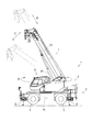
- FIG. 1 shows the crane 1 during traveling.
- FIG. 2 shows the crane 1 during the lifting operation.
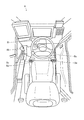
- FIG. 3 shows the interior of the cabin 8.
- the crane 1 is mainly composed of a traveling body 2 and a revolving body 3.
- the traveling body 2 includes a pair of left and right front tires 4 and a rear tire 5.
- the traveling body 2 includes an outrigger 6 that is grounded and stabilized when performing the lifting work.
- the traveling body 2 includes an engine, a transmission, and the like in addition to an actuator for driving them.
- the traveling body 2 includes a turning motor 25. For this reason, the traveling body 2 makes the revolving body 3 supported on the upper part freely turnable (see arrow A).
- the revolving unit 3 includes a boom 7 so as to protrude forward from the rear part.
- the boom 7 can be expanded and contracted by an expansion / contraction cylinder 35 (see arrow B). Further, the boom 7 can be raised and lowered by a raising and lowering cylinder 45 (see arrow C).
- the revolving unit 3 includes a cabin 8 on the right side of the boom 7.
- the cabin 8 is provided with a turning lever 8c, an extendable lever 8d, a hoisting lever 8e, and the like which are necessary for a lifting operation, in addition to a handle 8a and a shift lever 8b which are necessary for a traveling operation.
- an emergency key cylinder 8f is arranged in the crane 1, as an emergency key cylinder 8f is arranged.
- the hydraulic system H described below includes various actuators (a turning motor 25, a telescopic cylinder 35, and a hoisting cylinder 45). Furthermore, a main winding motor that constitutes the main winding winch and an auxiliary winding motor that constitutes the auxiliary winding winch may be included.
- FIG. 4 shows the configuration of the hydraulic system H.
- the continuous line and broken line in a figure show a hydraulic circuit
- the dashed-two dotted line in the figure has shown the electric circuit.
- the direction switching valve 20 is arranged in the hydraulic circuit.
- a hydraulic oil pipe 21 is connected to the direction switching valve 20. Therefore, hydraulic oil is supplied to the direction switching valve 20 through the hydraulic oil pipe 21.
- hydraulic oil pipes 22, 23, and 24 are connected to the direction switching valve 20. Therefore, when the spool slides to one side, the hydraulic oil flows to the hydraulic oil pipe 22, and when the spool slides to the other side, the hydraulic oil flows to the hydraulic oil pipe 23. In any case, the hydraulic oil is discharged through the hydraulic oil pipe 24.
- a turning motor 25 is arranged in the hydraulic circuit. Hydraulic oil pipes 22 and 23 are connected to the turning motor 25. Therefore, hydraulic oil is supplied to the turning motor 25 through the hydraulic oil pipe 22 or the hydraulic oil pipe 23.
- the turning motor 25 rotates to one side when the hydraulic oil is supplied through the hydraulic oil pipe 22, and rotates to the other side when the hydraulic oil is supplied through the hydraulic oil pipe 23.
- the turning motor 25 is connected to the turning body 3 through a structure (not shown). Therefore, when the turning motor 25 rotates in one direction, the revolving structure 3 turns in one direction. On the contrary, when the turning motor 25 rotates to the other side, the turning body 3 turns to the other side.
- a proportional pressure reducing valve 26 is arranged in the hydraulic circuit.
- a hydraulic oil pipe 27 is connected to the proportional pressure reducing valve 26. Therefore, hydraulic oil (pilot oil) is supplied to the proportional pressure reducing valve 26 through the hydraulic oil pipe 27.
- one end of the hydraulic oil pipe 28 is connected to the proportional pressure reducing valve 26, and the other end of the hydraulic oil pipe 28 is connected to the direction switching valve 20 described above. For this reason, when the spool is slid small, the pressure of the hydraulic oil (pilot pressure) also decreases, and the spool of the direction switching valve 20 is pushed with a small force.
- a direction switching valve 30 is arranged in the hydraulic circuit.
- a hydraulic oil pipe 31 is connected to the direction switching valve 30. Therefore, hydraulic oil is supplied to the direction switching valve 30 through the hydraulic oil pipe 31.
- hydraulic oil pipes 32, 33, and 34 are connected to the direction switching valve 30. Therefore, when the spool slides to one side, the hydraulic oil flows to the hydraulic oil pipe 32, and when the spool slides to the other side, the hydraulic oil flows to the hydraulic oil pipe 33. In any case, the hydraulic oil is discharged through the hydraulic oil pipe 34.
- a telescopic cylinder 35 is arranged in the hydraulic circuit. Hydraulic oil pipes 32 and 33 are connected to the expansion / contraction cylinder 35. Therefore, the hydraulic oil is supplied to the expansion / contraction cylinder 35 through the hydraulic oil pipe 32 or the hydraulic oil pipe 33.
- the expansion / contraction cylinder 35 expands when the hydraulic oil is supplied through the hydraulic oil pipe 32, and contracts when the hydraulic oil is supplied through the hydraulic oil pipe 33.
- the telescopic cylinder 35 is connected to the boom 7 through a structure (not shown). Therefore, when the telescopic cylinder 35 is extended, the boom 7 is extended accordingly. On the contrary, when the telescopic cylinder 35 contracts, the boom 7 contracts accordingly.
- a proportional pressure reducing valve 36 is arranged in the hydraulic circuit.
- a hydraulic oil pipe 37 is connected to the proportional pressure reducing valve 36. Therefore, hydraulic oil (pilot oil) is supplied to the proportional pressure reducing valve 36 through the hydraulic oil pipe 37.
- one end of a hydraulic oil pipe 38 is connected to the proportional pressure reducing valve 36, and the other end of the hydraulic oil pipe 38 is connected to the direction switching valve 30 described above. For this reason, when the spool is slid small, the pressure of the hydraulic oil (pilot pressure) is also small, and the spool of the direction switching valve 30 is pushed with a small force.
- a direction switching valve 40 is arranged in the hydraulic circuit.
- a hydraulic oil pipe 41 is connected to the direction switching valve 40. Therefore, hydraulic oil is supplied to the direction switching valve 40 through the hydraulic oil pipe 41.
- hydraulic oil pipes 42, 43, and 44 are connected to the direction switching valve 40. Therefore, when the spool slides to one side, the hydraulic oil flows to the hydraulic oil pipe 42, and when the spool slides to the other side, the hydraulic oil flows to the hydraulic oil pipe 43. In any case, the hydraulic oil is discharged through the hydraulic oil pipe 44.
- a undulation cylinder 45 is arranged in the hydraulic circuit. Hydraulic oil pipes 42 and 43 are connected to the undulation cylinder 45. Therefore, hydraulic oil is supplied to the undulation cylinder 45 through the hydraulic oil pipe 42 or the hydraulic oil pipe 43.
- the undulation cylinder 45 expands when the hydraulic oil is supplied through the hydraulic oil pipe 42 and contracts when the hydraulic oil is supplied through the hydraulic oil pipe 43.
- the hoisting cylinder 45 is connected to the boom 7 through a structure (not shown). Therefore, when the hoisting cylinder 45 is extended, the boom 7 is raised accordingly. On the contrary, when the hoisting cylinder 28 contracts, the boom 7 is lowered.
- a proportional pressure reducing valve 46 is arranged in the hydraulic circuit.
- a hydraulic oil pipe 47 is connected to the proportional pressure reducing valve 46. Therefore, hydraulic oil (pilot oil) is supplied to the proportional pressure reducing valve 46 through the hydraulic oil pipe 47.
- one end of the hydraulic oil pipe 48 is connected to the proportional pressure reducing valve 46, and the other end of the hydraulic oil pipe 48 is connected to the direction switching valve 40 described above. Therefore, when the spool is slid small, the hydraulic oil pressure (pilot pressure) is also small, and the spool of the direction switching valve 40 is pushed with a small force.
- an emergency proportional pressure reducing valve 50 is arranged in the hydraulic circuit.
- a hydraulic oil pipe 51 is connected to the emergency proportional pressure reducing valve 50. Therefore, hydraulic oil (pilot oil) is supplied to the emergency proportional pressure reducing valve 50 through the hydraulic oil pipe 51.
- one end of the hydraulic oil pipe 52 is connected to the emergency proportional pressure reducing valve 50 and is branched into the above-described three hydraulic oil pipes 27, 37, and 47. Therefore, when the spool is slid small, the pressure of the hydraulic oil (pilot pressure) is also reduced, and the spools of the respective direction switching valves 20, 30, 40 can be pushed with a small force.
- the position sensor 61 is arranged in the electric circuit. An electric wire 62 is connected to the position sensor 61. The position sensor 61 is attached to the turning lever 8c. Therefore, the position sensor 61 can detect the tilt angle of the turning lever 8c.
- a position sensor 63 is arranged in the electric circuit.
- An electric wire 64 is connected to the position sensor 63.
- the position sensor 63 is attached to the telescopic lever 8d. Therefore, the position sensor 63 can detect the tilt angle of the telescopic lever 8d.
- a position sensor 65 is arranged in the electric circuit.
- An electric wire 66 is connected to the position sensor 65.
- the position sensor 65 is attached to the hoisting lever 8e. Therefore, the position sensor 65 can detect the tilt angle of the hoisting lever 8e.
- an emergency operation switch 67 is arranged in the electric circuit.
- An electric wire 68 is connected to the emergency operation switch 67.
- the emergency operation switch 67 is attached to the emergency key cylinder 8f. Therefore, the emergency operation switch 67 can instruct to perform manual operation by inserting and turning the key.
- a controller 71 is arranged in the electric circuit. Electrical wires 62, 64, 66 and 68 are connected to the controller 71. Therefore, the controller 71 can recognize the tilt angle of the turning lever 8c, the tilt angle of the telescopic lever 8d, the tilt angle of the hoisting lever 8e, and the like.
- the controller 71 is connected to a plurality of electric wires 72, 73, 74, and 75.
- the electric wires 72, 73, 74, and 75 are connected to the proportional pressure reducing valves 26, 36, and 46 and the emergency proportional pressure reducing valve 50. Therefore, the controller 71 can appropriately control these valves 26, 36, 46, and 50.
- the emergency proportional pressure reducing valve 50 is controlled so as to keep the fully open state during normal times. The normal time indicates a situation in which the proportional pressure reducing valves 26, 36, and 46 are not malfunctioning.
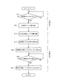
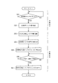
- FIG. 5 shows the processing of the controller 71 and the operation for moving the turning motor 25. Here, the description will be made on the assumption that the lifting work has already been performed.
- step S11 the controller 71 determines whether or not the emergency operation switch 67 is “ON”. If the emergency operation switch 67 is “ON”, the process proceeds to step S12.
- step S12 the controller 71 cuts off the energization of the proportional pressure reducing valve 26. Specifically, a signal is sent to a relay circuit (not shown) to cut off the power supplied to the proportional pressure reducing valve 26. Note that the proportional pressure reducing valve 26 is in a fully closed state when the power is cut off, so that the oil passage is closed (closed between the hydraulic oil pipe 27 and the hydraulic oil pipe 28). The reason for immediately stopping the flow of the hydraulic oil is that the oil passage is closed until the operator manually operates the proportional pressure reducing valve 26, and safety is improved.
- step S13 the controller 71 cuts off the energization of the emergency proportional pressure reducing valve 50. Specifically, a signal is sent to a relay circuit (not shown) to cut off the power supplied to the emergency proportional pressure reducing valve 50.
- the emergency proportional pressure reducing valve 50 is also in a fully closed state when the power is cut off, so that the oil passage is closed (closed between the hydraulic oil pipe 51 and the hydraulic oil pipe 52).
- the reason why the flow of hydraulic oil is stopped in a double manner is to improve safety. That is, in addition to the manual operation of the proportional pressure reducing valve 26, the oil passage is closed until the operator manually operates the emergency proportional pressure reducing valve 50, and the safety is further improved.
- step S14 the operator tightens the screw 26s of the proportional pressure reducing valve 26. Specifically, the screw 26s provided in the proportional pressure reducing valve 26 is picked, and the screw 26s is tightened to the end. As a result, the spool of the proportional pressure reducing valve 26 is moved by being pushed by the screw 26s, so that the oil passage can be opened (connecting between the hydraulic oil pipe 27 and the hydraulic oil pipe 28). Note that, in the proportional pressure reducing valve 26, the coil 26s is not excited by cutting off the electric power, so that it is easy to tighten the screw 26s.
- step S15 the operator pushes the push rod 50r of the emergency proportional pressure reducing valve 50.
- the push rod 50r provided in the emergency proportional pressure reducing valve 50 is picked and the push rod 50r is pushed to an appropriate position.
- the spool of the emergency proportional pressure reducing valve 50 is moved by being pushed by the push rod 50r, so that the oil passage can be opened (connecting between the hydraulic oil pipe 51 and the hydraulic oil pipe 52).
- the hydraulic oil pressure (pilot pressure) changes in accordance with the push-in amount of the push rod 50r, the force applied to the spool of the direction switching valve 20 also changes.
- the emergency proportional pressure reducing valve 50 is easy to push in the push rod 50r because the coil is not excited by the power interruption. That is, manual operation is easy. As a result, the hydraulic oil pressure (pilot pressure) can be adjusted quickly and easily.
- step S ⁇ b> 16 the operator determines whether or not the swing body 3 has swung to the storage position of the boom 7. If it is the storage position of the boom 7, it will transfer to step S17.
- step S17 the operator pulls out the push rod 50r of the emergency proportional pressure reducing valve 50. Specifically, the push rod 50r provided in the emergency proportional pressure reducing valve 50 is picked and all the push rods 50r are pulled out. As a result, the spool of the emergency proportional pressure reducing valve 50 moves to the neutral position, so that the oil passage can be closed again (closed between the hydraulic oil pipe 51 and the hydraulic oil pipe 52).
- the crane 1 can adjust the pressure of the hydraulic oil (pilot pressure) by manual operation even when the proportional pressure reducing valve 26 breaks down, and can move the turning motor 25 at an appropriate speed. it can.
- the revolving structure 3 can be revolved to the retracted position of the boom 7.
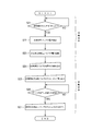
- FIG. 6 shows the processing of the controller 71 and the operation for moving the telescopic cylinder 35.
- the description will be made on the assumption that the lifting work has already been performed.
- step S21 the controller 71 determines whether or not the emergency operation switch 67 is “ON”. If the emergency operation switch 67 is “ON”, the process proceeds to step S22.
- step S22 the controller 71 cuts off the energization of the proportional pressure reducing valve 36. Specifically, a signal is sent to a relay circuit (not shown) to cut off the power supplied to the proportional pressure reducing valve 36. Note that the proportional pressure reducing valve 36 is in a fully closed state when the power is cut off, so that the oil passage is closed (closed between the hydraulic oil pipe 37 and the hydraulic oil pipe 38). The reason for immediately stopping the flow of the hydraulic oil is that the oil passage is closed until the operator manually operates the proportional pressure reducing valve 36, and the safety is improved.
- step S23 the controller 71 cuts off the energization of the emergency proportional pressure reducing valve 50. Specifically, a signal is sent to a relay circuit (not shown) to cut off the power supplied to the emergency proportional pressure reducing valve 50.
- the emergency proportional pressure reducing valve 50 is also in a fully closed state when the power is cut off, so that the oil passage is closed (closed between the hydraulic oil pipe 51 and the hydraulic oil pipe 52).
- the reason why the flow of hydraulic oil is stopped in a double manner is to improve safety. That is, in addition to the manual operation of the proportional pressure reducing valve 36, the oil passage is closed until the operator manually operates the emergency proportional pressure reducing valve 50, and the safety is further improved.
- step S24 the operator tightens the screw 36s of the proportional pressure reducing valve 36. Specifically, the screw 36s provided in the proportional pressure reducing valve 36 is picked, and the screw 36s is tightened to the end. As a result, the spool of the proportional pressure reducing valve 36 is pushed and moved by the screw 36s, so that the oil passage can be opened (connecting between the hydraulic oil pipe 37 and the hydraulic oil pipe 38). Note that, in the proportional pressure reducing valve 36, the coil 36s is not excited by power interruption, so that it is easy to tighten the screw 36s.
- step S25 the operator pushes the push rod 50r of the emergency proportional pressure reducing valve 50.
- the push rod 50r provided in the emergency proportional pressure reducing valve 50 is picked and the push rod 50r is pushed to an appropriate position.
- the spool of the emergency proportional pressure reducing valve 50 is moved by being pushed by the push rod 50r, so that the oil passage can be opened (connecting between the hydraulic oil pipe 51 and the hydraulic oil pipe 52). Since the pressure of the hydraulic oil (pilot pressure) changes according to the push amount of the push rod 50r, the force applied to the spool of the direction switching valve 30 also changes.
- the emergency proportional pressure reducing valve 50 is easy to push in the push rod 50r because the coil is not excited by the power interruption. That is, manual operation is easy. As a result, the hydraulic oil pressure (pilot pressure) can be adjusted quickly and easily.
- step S26 the operator determines whether or not the boom 7 is completely contracted. If the boom 7 is completely contracted, the process proceeds to step S27.
- step S27 the operator pulls out the push rod 50r of the emergency proportional pressure reducing valve 50. Specifically, the push rod 50r provided in the emergency proportional pressure reducing valve 50 is picked and all the push rods 50r are pulled out. As a result, the spool of the emergency proportional pressure reducing valve 50 moves to the neutral position, so that the oil passage can be closed again (closed between the hydraulic oil pipe 51 and the hydraulic oil pipe 52).
- the crane 1 can adjust the pressure of the hydraulic oil (pilot pressure) by manual operation even when the proportional pressure reducing valve 36 is broken, and can move the expansion / contraction cylinder 35 at an appropriate speed. it can.
- the boom 7 can be completely contracted.
- FIG. 7 shows the processing of the controller 71 and the operation for moving the undulation cylinder 45.
- the description will be made on the assumption that the lifting work has already been performed.
- step S31 the controller 71 determines whether or not the emergency operation switch 67 is “ON”. If the emergency operation switch 67 is “ON”, the process proceeds to step S32.
- step S32 the controller 71 cuts off the energization of the proportional pressure reducing valve 46. Specifically, a signal is sent to a relay circuit (not shown) to cut off the power supplied to the proportional pressure reducing valve 46.
- the proportional pressure reducing valve 46 has a specification in which the proportional pressure reducing valve 46 is fully closed when the power is cut off, so that the oil passage is closed (closed between the hydraulic oil pipe 47 and the hydraulic oil pipe 48). The reason for immediately stopping the flow of the hydraulic oil is that the oil passage is closed until the operator manually operates the proportional pressure reducing valve 46, and safety is improved.
- step S33 the controller 71 cuts off the energization of the emergency proportional pressure reducing valve 50. Specifically, a signal is sent to a relay circuit (not shown) to cut off the power supplied to the emergency proportional pressure reducing valve 50.
- the emergency proportional pressure reducing valve 50 is also in a fully closed state when the power is shut off, so that the hydraulic oil passage is closed (between the hydraulic oil pipe 51 and the hydraulic oil pipe 52). Become.
- the reason why the flow of hydraulic oil is stopped in a double manner is to improve safety. That is, in addition to the manual operation of the proportional pressure reducing valve 46, the oil passage is closed until the operator manually operates the emergency proportional pressure reducing valve 50, and the safety is further improved.
- step S34 the operator tightens the screw 46s of the proportional pressure reducing valve 46. Specifically, the screw 46s provided in the proportional pressure reducing valve 46 is picked and the screw 46s is tightened to the end. As a result, the spool of the proportional pressure reducing valve 46 is moved by being pushed by the screw 46s, so that the oil passage can be opened (the connection between the hydraulic oil pipe 37 and the hydraulic oil pipe 38). In the proportional pressure reducing valve 46, since the coil is not excited by the power interruption, it is easy to tighten the screw 46s.
- step S35 the operator pushes the push rod 50r of the emergency proportional pressure reducing valve 50.
- the push rod 50r provided in the emergency proportional pressure reducing valve 50 is picked and the push rod 50r is pushed to an appropriate position.
- the spool of the emergency proportional pressure reducing valve 50 is moved by being pushed by the push rod 50r, so that the oil passage can be opened (connecting between the hydraulic oil pipe 51 and the hydraulic oil pipe 52). Since the pressure of the hydraulic oil (pilot pressure) changes according to the push amount of the push rod 50r, the force applied to the spool of the direction switching valve 40 also changes.
- the emergency proportional pressure reducing valve 50 is easy to push in the push rod 50r because the coil is not excited by the power interruption. That is, manual operation is easy. As a result, the hydraulic oil pressure (pilot pressure) can be adjusted quickly and easily.
- step S36 the operator determines whether or not the boom 7 is completely lying down. If the boom 7 is completely lying down, the process proceeds to step S37.
- step S37 the operator pulls out the push rod 50r of the emergency proportional pressure reducing valve 50. Specifically, the push rod 50r provided in the emergency proportional pressure reducing valve 50 is picked and all the push rods 50r are pulled out. As a result, the spool of the emergency proportional pressure reducing valve 50 moves to the neutral position, so that the oil passage can be closed again (closed between the hydraulic oil pipe 51 and the hydraulic oil pipe 52).
- the crane 1 can adjust the pressure (pilot pressure) of the hydraulic oil by manual operation even when the proportional pressure reducing valve 46 is broken, and can move the hoisting cylinder 45 at an appropriate speed. it can.
- the boom 7 can be completely laid down.
- the crane 1 is provided with oil passages (hydraulic oil pipes 51 and 52) for guiding hydraulic oil to one or a plurality of proportional pressure reducing valves 26, 36 and 46, and the oil passages (51 and 52).
- An emergency proportional pressure reducing valve 50 that can adjust the opening degree by manual operation is arranged.
- the emergency proportional pressure reducing valve 50 is controlled so as to be kept fully open during normal times, and is a manual operation tool for adjusting the pressure of hydraulic oil without being controlled during emergency times. According to the crane 1, even when the proportional pressure reducing valves 26, 36, 46 are out of order, the hydraulic oil pressure can be adjusted by manual operation of the emergency proportional pressure reducing valve 50.
- the actuator the turning motor 25, the expansion / contraction cylinder 35, and the hoisting cylinder 45
- the actuator can be moved at an appropriate speed.
- the crane 1 further includes a controller 71 that can control the emergency proportional pressure reducing valve 50 and an emergency operation switch 67 that can instruct the controller 71 to perform an emergency operation. Then, when the emergency operation switch 67 is turned on, the controller 71 cuts off the power supplied to the emergency proportional pressure reducing valve 50. According to the crane 1, manual operation of the emergency proportional pressure reducing valve 50 is facilitated, so that the pressure of the hydraulic oil can be adjusted quickly and easily.
- the emergency proportional pressure reducing valve 50 is a specification that is fully closed when the power is cut off. According to the crane 1, the oil passage is closed until the operator manually operates the emergency proportional pressure reducing valve 50, so that safety can be further improved.
Landscapes
- Engineering & Computer Science (AREA)
- Mechanical Engineering (AREA)
- Physics & Mathematics (AREA)
- Fluid Mechanics (AREA)
- General Engineering & Computer Science (AREA)
- Fluid-Pressure Circuits (AREA)
- Chemical & Material Sciences (AREA)
- Analytical Chemistry (AREA)
- Automation & Control Theory (AREA)
- Control And Safety Of Cranes (AREA)
- Jib Cranes (AREA)
Abstract
La présente invention concerne une grue 1 constituant un système hydraulique H qui comprend : des actionneurs 25, 35, 45; des vannes de commutation de direction 20, 30, 40 qui commutent la direction d'écoulement d'un fluide de travail pour actionner les actionneurs 25, 35, 45 ; et des vannes de dépressurisation proportionnelle 26, 36, 46 qui permettent le réglage de la pression d'un fluide de travail pour actionner les vannes de commutation de direction 20, 30, 40, des passages d'écoulement 51, 52 étant disposés pour guider le fluide de travail vers une ou plusieurs vannes de dépressurisation proportionnelle 26, 36, 46, et une vanne de dépressurisation proportionnelle d'urgence 50, dont le degré d'ouverture peut être réglé par une opération manuelle est disposée dans les passages d'écoulement 51, 52. La vanne de dépressurisation proportionnelle d'urgence 50 est commandée de façon à maintenir un état complètement ouvert pendant des périodes normales et sert d'outil actionnable manuellement pour régler la pression du fluide de travail sans être commandé pendant une urgence.
Applications Claiming Priority (2)
| Application Number | Priority Date | Filing Date | Title |
|---|---|---|---|
| JP2016-095684 | 2016-05-11 | ||
| JP2016095684A JP2017202909A (ja) | 2016-05-11 | 2016-05-11 | クレーン |
Publications (1)
| Publication Number | Publication Date |
|---|---|
| WO2017195716A1 true WO2017195716A1 (fr) | 2017-11-16 |
Family
ID=60267194
Family Applications (1)
| Application Number | Title | Priority Date | Filing Date |
|---|---|---|---|
| PCT/JP2017/017341 Ceased WO2017195716A1 (fr) | 2016-05-11 | 2017-05-08 | Grue |
Country Status (2)
| Country | Link |
|---|---|
| JP (1) | JP2017202909A (fr) |
| WO (1) | WO2017195716A1 (fr) |
Cited By (1)
| Publication number | Priority date | Publication date | Assignee | Title |
|---|---|---|---|---|
| DE102022113302A1 (de) | 2022-05-25 | 2023-11-30 | Liebherr-Werk Ehingen Gmbh | Hydrauliksystem zur Druckversorgung eines hydraulischen Aktuators |
Families Citing this family (2)
| Publication number | Priority date | Publication date | Assignee | Title |
|---|---|---|---|---|
| KR102372010B1 (ko) * | 2020-05-21 | 2022-03-08 | 대흥중공업 주식회사 | 크레인 |
| CN116216546A (zh) * | 2023-02-28 | 2023-06-06 | 三一汽车起重机械有限公司 | 一种油缸缓冲控制方法、系统、油缸及起重机 |
Citations (5)
| Publication number | Priority date | Publication date | Assignee | Title |
|---|---|---|---|---|
| JPS6268004U (fr) * | 1985-10-18 | 1987-04-28 | ||
| JPH0214811U (fr) * | 1988-07-13 | 1990-01-30 | ||
| JP2972530B2 (ja) * | 1994-11-16 | 1999-11-08 | 新キャタピラー三菱株式会社 | 建設機械の作業機制御装置 |
| JP3037677B1 (ja) * | 1999-01-26 | 2000-04-24 | 新キャタピラー三菱株式会社 | 作業用機械の油圧制御回路 |
| CN103740878A (zh) * | 2013-12-24 | 2014-04-23 | 江苏永钢集团有限公司 | 一种高炉炉顶布料控制装置 |
-
2016
- 2016-05-11 JP JP2016095684A patent/JP2017202909A/ja active Pending
-
2017
- 2017-05-08 WO PCT/JP2017/017341 patent/WO2017195716A1/fr not_active Ceased
Patent Citations (5)
| Publication number | Priority date | Publication date | Assignee | Title |
|---|---|---|---|---|
| JPS6268004U (fr) * | 1985-10-18 | 1987-04-28 | ||
| JPH0214811U (fr) * | 1988-07-13 | 1990-01-30 | ||
| JP2972530B2 (ja) * | 1994-11-16 | 1999-11-08 | 新キャタピラー三菱株式会社 | 建設機械の作業機制御装置 |
| JP3037677B1 (ja) * | 1999-01-26 | 2000-04-24 | 新キャタピラー三菱株式会社 | 作業用機械の油圧制御回路 |
| CN103740878A (zh) * | 2013-12-24 | 2014-04-23 | 江苏永钢集团有限公司 | 一种高炉炉顶布料控制装置 |
Cited By (2)
| Publication number | Priority date | Publication date | Assignee | Title |
|---|---|---|---|---|
| DE102022113302A1 (de) | 2022-05-25 | 2023-11-30 | Liebherr-Werk Ehingen Gmbh | Hydrauliksystem zur Druckversorgung eines hydraulischen Aktuators |
| DE102022113302B4 (de) | 2022-05-25 | 2023-12-14 | Liebherr-Werk Ehingen Gmbh | Hydrauliksystem zur Druckversorgung eines hydraulischen Aktuators |
Also Published As
| Publication number | Publication date |
|---|---|
| JP2017202909A (ja) | 2017-11-16 |
Similar Documents
| Publication | Publication Date | Title |
|---|---|---|
| JP5052147B2 (ja) | 建設車両用ステアリング装置 | |
| KR101767857B1 (ko) | 작업 기계의 유압 시스템 | |
| WO2017171021A1 (fr) | Système hydraulique et procédé d'opération d'urgence | |
| CN111356844B (zh) | 油压驱动系统 | |
| WO2015151582A1 (fr) | Machine de travail | |
| JP2017202909A (ja) | クレーン | |
| JP3946176B2 (ja) | 油圧ショベルの油圧回路 | |
| JP3768989B2 (ja) | 重装備オプション装置用油圧回路 | |
| EP3779212B1 (fr) | Circuit hydraulique pour véhicule de travail | |
| JP7297401B2 (ja) | ショベル | |
| WO2021039287A1 (fr) | Système hydraulique pour engin de chantier | |
| JP4166604B2 (ja) | ウインチの速度制御装置およびクレーン | |
| JP2007064446A (ja) | 建設機械の油圧制御装置 | |
| WO2017175865A1 (fr) | Grue | |
| JP4838555B2 (ja) | 油圧回路及び電気制御回路並びに油圧モータ切断装置 | |
| JP2008256048A (ja) | 昇降運転室を備えた旋回作業車 | |
| JP7001554B2 (ja) | クレーン機能付き油圧ショベル | |
| JP2003268750A (ja) | ゲート開閉装置 | |
| JP2003020692A (ja) | 油圧ショベルの油圧回路 | |
| JP2004359421A (ja) | クローラクレーンの油圧装置 | |
| JP4714489B2 (ja) | クレーンの油圧回路 | |
| JP7342437B2 (ja) | 作業機械 | |
| JPH0754813A (ja) | 油圧アクチユエータ用のバルブ制御装置 | |
| JP2000103590A (ja) | 作業機械の安全装置 | |
| JP2578636Y2 (ja) | 作業車両 |
Legal Events
| Date | Code | Title | Description |
|---|---|---|---|
| NENP | Non-entry into the national phase |
Ref country code: DE |
|
| 121 | Ep: the epo has been informed by wipo that ep was designated in this application |
Ref document number: 17796077 Country of ref document: EP Kind code of ref document: A1 |
|
| 122 | Ep: pct application non-entry in european phase |
Ref document number: 17796077 Country of ref document: EP Kind code of ref document: A1 |