WO2017195724A1 - Système de communication - Google Patents
Système de communication Download PDFInfo
- Publication number
- WO2017195724A1 WO2017195724A1 PCT/JP2017/017367 JP2017017367W WO2017195724A1 WO 2017195724 A1 WO2017195724 A1 WO 2017195724A1 JP 2017017367 W JP2017017367 W JP 2017017367W WO 2017195724 A1 WO2017195724 A1 WO 2017195724A1
- Authority
- WO
- WIPO (PCT)
- Prior art keywords
- cell
- interference
- mimo
- transmission path
- cells
- Prior art date
- Legal status (The legal status is an assumption and is not a legal conclusion. Google has not performed a legal analysis and makes no representation as to the accuracy of the status listed.)
- Ceased
Links
Images


Classifications
-
- H—ELECTRICITY
- H04—ELECTRIC COMMUNICATION TECHNIQUE
- H04B—TRANSMISSION
- H04B7/00—Radio transmission systems, i.e. using radiation field
- H04B7/02—Diversity systems; Multi-antenna system, i.e. transmission or reception using multiple antennas
- H04B7/022—Site diversity; Macro-diversity
- H04B7/024—Co-operative use of antennas of several sites, e.g. in co-ordinated multipoint or co-operative multiple-input multiple-output [MIMO] systems
-
- H—ELECTRICITY
- H04—ELECTRIC COMMUNICATION TECHNIQUE
- H04B—TRANSMISSION
- H04B7/00—Radio transmission systems, i.e. using radiation field
- H04B7/02—Diversity systems; Multi-antenna system, i.e. transmission or reception using multiple antennas
- H04B7/04—Diversity systems; Multi-antenna system, i.e. transmission or reception using multiple antennas using two or more spaced independent antennas
- H04B7/0413—MIMO systems
-
- H—ELECTRICITY
- H04—ELECTRIC COMMUNICATION TECHNIQUE
- H04B—TRANSMISSION
- H04B17/00—Monitoring; Testing
- H04B17/30—Monitoring; Testing of propagation channels
- H04B17/309—Measuring or estimating channel quality parameters
- H04B17/336—Signal-to-interference ratio [SIR] or carrier-to-interference ratio [CIR]
-
- H—ELECTRICITY
- H04—ELECTRIC COMMUNICATION TECHNIQUE
- H04B—TRANSMISSION
- H04B7/00—Radio transmission systems, i.e. using radiation field
- H04B7/02—Diversity systems; Multi-antenna system, i.e. transmission or reception using multiple antennas
- H04B7/04—Diversity systems; Multi-antenna system, i.e. transmission or reception using multiple antennas using two or more spaced independent antennas
- H04B7/0413—MIMO systems
- H04B7/0452—Multi-user MIMO systems
-
- H—ELECTRICITY
- H04—ELECTRIC COMMUNICATION TECHNIQUE
- H04B—TRANSMISSION
- H04B7/00—Radio transmission systems, i.e. using radiation field
- H04B7/02—Diversity systems; Multi-antenna system, i.e. transmission or reception using multiple antennas
- H04B7/04—Diversity systems; Multi-antenna system, i.e. transmission or reception using multiple antennas using two or more spaced independent antennas
- H04B7/06—Diversity systems; Multi-antenna system, i.e. transmission or reception using multiple antennas using two or more spaced independent antennas at the transmitting station
- H04B7/0613—Diversity systems; Multi-antenna system, i.e. transmission or reception using multiple antennas using two or more spaced independent antennas at the transmitting station using simultaneous transmission
- H04B7/0615—Diversity systems; Multi-antenna system, i.e. transmission or reception using multiple antennas using two or more spaced independent antennas at the transmitting station using simultaneous transmission of weighted versions of same signal
- H04B7/0619—Diversity systems; Multi-antenna system, i.e. transmission or reception using multiple antennas using two or more spaced independent antennas at the transmitting station using simultaneous transmission of weighted versions of same signal using feedback from receiving side
- H04B7/0621—Feedback content
- H04B7/0626—Channel coefficients, e.g. channel state information [CSI]
-
- H—ELECTRICITY
- H04—ELECTRIC COMMUNICATION TECHNIQUE
- H04L—TRANSMISSION OF DIGITAL INFORMATION, e.g. TELEGRAPHIC COMMUNICATION
- H04L5/00—Arrangements affording multiple use of the transmission path
- H04L5/003—Arrangements for allocating sub-channels of the transmission path
- H04L5/0048—Allocation of pilot signals, i.e. of signals known to the receiver
- H04L5/005—Allocation of pilot signals, i.e. of signals known to the receiver of common pilots, i.e. pilots destined for multiple users or terminals
-
- H—ELECTRICITY
- H04—ELECTRIC COMMUNICATION TECHNIQUE
- H04L—TRANSMISSION OF DIGITAL INFORMATION, e.g. TELEGRAPHIC COMMUNICATION
- H04L5/00—Arrangements affording multiple use of the transmission path
- H04L5/003—Arrangements for allocating sub-channels of the transmission path
- H04L5/0053—Allocation of signalling, i.e. of overhead other than pilot signals
- H04L5/0057—Physical resource allocation for CQI
-
- H—ELECTRICITY
- H04—ELECTRIC COMMUNICATION TECHNIQUE
- H04W—WIRELESS COMMUNICATION NETWORKS
- H04W16/00—Network planning, e.g. coverage or traffic planning tools; Network deployment, e.g. resource partitioning or cells structures
- H04W16/24—Cell structures
- H04W16/28—Cell structures using beam steering
-
- H—ELECTRICITY
- H04—ELECTRIC COMMUNICATION TECHNIQUE
- H04W—WIRELESS COMMUNICATION NETWORKS
- H04W24/00—Supervisory, monitoring or testing arrangements
- H04W24/10—Scheduling measurement reports ; Arrangements for measurement reports
-
- H—ELECTRICITY
- H04—ELECTRIC COMMUNICATION TECHNIQUE
- H04W—WIRELESS COMMUNICATION NETWORKS
- H04W76/00—Connection management
- H04W76/20—Manipulation of established connections
- H04W76/27—Transitions between radio resource control [RRC] states
-
- H—ELECTRICITY
- H04—ELECTRIC COMMUNICATION TECHNIQUE
- H04L—TRANSMISSION OF DIGITAL INFORMATION, e.g. TELEGRAPHIC COMMUNICATION
- H04L5/00—Arrangements affording multiple use of the transmission path
- H04L5/0001—Arrangements for dividing the transmission path
- H04L5/0014—Three-dimensional division
- H04L5/0023—Time-frequency-space
-
- H—ELECTRICITY
- H04—ELECTRIC COMMUNICATION TECHNIQUE
- H04L—TRANSMISSION OF DIGITAL INFORMATION, e.g. TELEGRAPHIC COMMUNICATION
- H04L5/00—Arrangements affording multiple use of the transmission path
- H04L5/003—Arrangements for allocating sub-channels of the transmission path
- H04L5/0058—Allocation criteria
- H04L5/0073—Allocation arrangements that take into account other cell interferences
-
- H—ELECTRICITY
- H04—ELECTRIC COMMUNICATION TECHNIQUE
- H04W—WIRELESS COMMUNICATION NETWORKS
- H04W74/00—Wireless channel access
- H04W74/08—Non-scheduled access, e.g. ALOHA
- H04W74/0833—Random access procedures, e.g. with 4-step access
-
- H—ELECTRICITY
- H04—ELECTRIC COMMUNICATION TECHNIQUE
- H04W—WIRELESS COMMUNICATION NETWORKS
- H04W92/00—Interfaces specially adapted for wireless communication networks
- H04W92/16—Interfaces between hierarchically similar devices
- H04W92/20—Interfaces between hierarchically similar devices between access points
Definitions
- the present invention relates to a communication system that performs wireless communication between a communication terminal device such as a mobile terminal device and a base station device.
- LTE Long Term Evolution
- network the core network and radio access network
- SAE System Architecture Evolution
- OFDM Orthogonal Frequency Division Multiplexing
- SC-FDMA Single Carrier Frequency Division Multiple Access
- W-CDMA Wideband Code Division Multiple Access
- Non-Patent Document 1 (Chapter 5), 3GPP determination items related to the frame configuration in the LTE system will be described with reference to FIG.
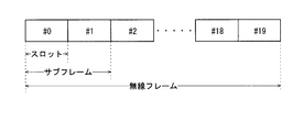
- FIG. 1 is an explanatory diagram showing a configuration of a radio frame used in an LTE communication system.
- one radio frame (Radio frame) is 10 ms.
- the radio frame is divided into ten equally sized subframes.
- the subframe is divided into two equally sized slots.
- a downlink synchronization signal (Downlink Synchronization Signal) is included in the first and sixth subframes for each radio frame.
- the synchronization signal includes a first synchronization signal (Primary Synchronization Signal: P-SS) and a second synchronization signal (Secondary Synchronization Signal: S-SS).
- Non-Patent Document 1 (Chapter 5) describes the decision items regarding the channel configuration in the LTE system in 3GPP. It is assumed that the same channel configuration as that of the non-CSG cell is used in a CSG (Closed Subscriber Group) cell.
- a physical broadcast channel (Physical Broadcast Channel: PBCH) is a communication terminal device such as a base station device (hereinafter simply referred to as “base station”) to a mobile terminal device (hereinafter also simply referred to as “mobile terminal”). It is a channel for downlink transmission to (hereinafter sometimes simply referred to as “communication terminal”).
- a BCH transport block (transport block) is mapped to four subframes in a 40 ms interval. There is no obvious signaling of 40ms timing.
- the physical control format indicator channel (Physical Control Format Indicator Channel: PCFICH) is a channel for downlink transmission from the base station to the communication terminal.
- the PCFICH notifies the communication terminal of the number of OFDM (Orthogonal Frequency Division Multiplexing) symbols used for PDCCHs.
- PCFICH is transmitted for each subframe.
- the physical downlink control channel (Physical Downlink Control Channel: PDCCH) is a channel for downlink transmission from the base station to the communication terminal.
- the PDCCH includes resource allocation (allocation) information of a downlink shared channel (DL-SCH), which is one of transport channels described later, and a paging channel (Paging channel: PCH, one of transport channels described later). ) Resource allocation (allocation) information and HARQ (Hybrid Automatic Repeat reQuest) information related to DL-SCH.
- the PDCCH carries an uplink scheduling grant (Uplink Scheduling Grant).
- the PDCCH carries Ack (Acknowledgement) / Nack (Negative Acknowledgment) which is a response signal for uplink transmission.
- the PDCCH is also called an L1 / L2 control signal.
- a physical downlink shared channel is a channel for downlink transmission from a base station to a communication terminal.
- a downlink shared channel (DL-SCH) that is a transport channel and PCH that is a transport channel are mapped.
- the physical multicast channel (Physical Multicast Channel: PMCH) is a channel for downlink transmission from the base station to the communication terminal.
- a multicast channel (Multicast Channel: MCH) that is a transport channel is mapped to the PMCH.
- a physical uplink control channel (Physical Uplink Control Channel: PUCCH) is a channel for uplink transmission from a communication terminal to a base station.
- the PUCCH carries Ack / Nack which is a response signal (response signal) for downlink transmission.
- the PUCCH carries a CQI (Channel Quality Indicator) report.
- CQI is quality information indicating the quality of received data or channel quality.
- the PUCCH carries a scheduling request (SR).
- SR scheduling request
- the physical uplink shared channel (Physical Uplink Shared Channel: PUSCH) is a channel for uplink transmission from the communication terminal to the base station.
- An uplink shared channel (Uplink Shared Channel: UL-SCH), which is one of the transport channels, is mapped to the PUSCH.
- a physical HARQ indicator channel (Physical Hybrid ARQ Indicator Channel: PHICH) is a channel for downlink transmission from the base station to the communication terminal. PHICH carries Ack / Nack which is a response signal for uplink transmission.
- a physical random access channel (Physical Random Access Channel: PRACH) is a channel for uplink transmission from a communication terminal to a base station. The PRACH carries a random access preamble.
- the downlink reference signal (Reference Signal: RS) is a symbol known as an LTE communication system.
- the following five types of downlink reference signals are defined.
- Cell specific reference signal Cell-specific Reference Signal: CRS
- MBSFN reference signal MBSFN Reference Signal
- UE specific reference signal UE-specific Reference Signal: Signal demodulation reference signal (Demodulation Reference Signal: DM-RS)
- Position determination reference signal Position determination reference signal
- PRS Position determination reference signal
- CSI-RS Channel State Information Reference Signal
- RSRP reference signal received power
- Non-Patent Document 1 (Chapter 5) will be described.
- a broadcast channel (Broadcast Channel: BCH) is broadcast to the entire coverage of the base station (cell).
- the BCH is mapped to the physical broadcast channel (PBCH).
- PBCH physical broadcast channel
- HARQ Hybrid ARQ
- DL-SCH downlink shared channel
- the DL-SCH can be broadcast to the entire coverage of the base station (cell).
- DL-SCH supports dynamic or semi-static resource allocation. Quasi-static resource allocation is also referred to as persistent scheduling.
- the DL-SCH supports discontinuous reception (DRX) of the communication terminal in order to reduce the power consumption of the communication terminal.
- the DL-SCH is mapped to the physical downlink shared channel (PDSCH).
- the paging channel supports DRX of the communication terminal in order to enable low power consumption of the communication terminal.
- the PCH is required to be broadcast to the entire coverage of the base station (cell).
- the PCH is mapped to a physical resource such as a physical downlink shared channel (PDSCH) that can be dynamically used for traffic.
- PDSCH physical downlink shared channel
- a multicast channel (Multicast Channel: MCH) is used for broadcasting to the entire coverage of a base station (cell).
- the MCH supports SFN combining of MBMS (Multimedia Broadcast Multicast Service) services (MTCH and MCCH) in multi-cell transmission.
- MTCH and MCCH Multimedia Broadcast Multicast Service
- the MCH supports quasi-static resource allocation.
- MCH is mapped to PMCH.
- HARQ Hybrid ARQ
- PUSCH physical uplink shared channel
- Random Access Channel is limited to control information. RACH is at risk of collision.
- the RACH is mapped to a physical random access channel (PRACH).
- PRACH physical random access channel
- HARQ is a technique for improving the communication quality of a transmission path by a combination of an automatic repeat request (Automatic Repeat reQuest: ARQ) and error correction (Forward Error Correction).
- ARQ Automatic Repeat reQuest
- error correction Forward Error Correction
- HARQ has an advantage that error correction functions effectively by retransmission even for a transmission path whose communication quality changes. In particular, further quality improvement can be obtained by combining the initial transmission reception result and the retransmission reception result upon retransmission.
- BCCH Broadcast Control Channel
- BCH Broadcast Control Channel
- DL-SCH downlink shared channel
- the paging control channel (Paging Control Channel: PCCH) is a downlink channel for transmitting changes in paging information (Paging Information) and system information (System Information).
- PCCH is used when the network does not know the cell location of the communication terminal.
- the PCCH that is a logical channel is mapped to a paging channel (PCH) that is a transport channel.
- PCH paging channel
- the common control channel (Common Control Channel: CCCH) is a channel for transmission control information between the communication terminal and the base station. CCCH is used when the communication terminal does not have an RRC connection with the network.
- CCCH is mapped to a downlink shared channel (DL-SCH) that is a transport channel.
- DL-SCH downlink shared channel
- UL-SCH uplink shared channel
- the multicast control channel (Multicast Control Channel: MCCH) is a downlink channel for one-to-many transmission. MCCH is used for transmission of MBMS control information for one or several MTCHs from a network to a communication terminal. MCCH is used only for communication terminals receiving MBMS.
- the MCCH is mapped to a multicast channel (MCH) that is a transport channel.
- the dedicated control channel (Dedicated Control Channel: DCCH) is a channel for transmitting individual control information between the communication terminal and the network on a one-to-one basis.
- the DCCH is used when the communication terminal is an RRC connection.
- the DCCH is mapped to the uplink shared channel (UL-SCH) in the uplink, and is mapped to the downlink shared channel (DL-SCH) in the downlink.
- the dedicated traffic channel (Dedicated Traffic Channel: DTCH) is a channel for one-to-one communication to individual communication terminals for transmitting user information.
- DTCH exists for both uplink and downlink.
- the DTCH is mapped to the uplink shared channel (UL-SCH) in the uplink, and is mapped to the downlink shared channel (DL-SCH) in the downlink.
- UL-SCH uplink shared channel
- DL-SCH downlink shared channel
- a multicast traffic channel is a downlink channel for transmitting traffic data from a network to a communication terminal.
- MTCH is a channel used only for communication terminals receiving MBMS.
- the MTCH is mapped to a multicast channel (MCH).
- CGI is a Cell Global Identifier.
- ECGI is an E-UTRAN cell global identifier (E-UTRAN Cell Global Identifier).
- LTE Long Term Evolution Advanced
- UMTS Universal Mobile Telecommunication System
- a CSG (Closed Subscriber Group) cell is a cell in which an operator identifies an available subscriber (hereinafter, may be referred to as a “specific subscriber cell”).
- the identified subscribers are allowed to access one or more cells of the PLMN (Public Land Mobile Mobile Network).
- PLMN Public Land Mobile Mobile Network
- One or more cells to which the identified subscribers are allowed access are called “CSG cells (CSG cell (s))”.
- CSG cell (s) Public Land Mobile Mobile Network
- PLMN Public Land Mobile Mobile Network
- the CSG cell is a part of a PLMN that broadcasts a unique CSG identity (CSG identity: CSG-ID) and broadcasts “TRUE” by CSG indication (CSG indication). Members of the subscriber group who have been registered in advance and permitted access the CSG cell using the CSG-ID as access permission information.
- CSG identity CSG-ID
- CSG indication CSG indication
- the CSG-ID is broadcast by the CSG cell or cell. There are a plurality of CSG-IDs in an LTE communication system. The CSG-ID is then used by the communication terminal (UE) to facilitate access of CSG related members.
- UE communication terminal
- the location tracking of communication terminals is performed in units of one or more cells.
- the position tracking is performed to track the position of the communication terminal and call the communication terminal even in the standby state, in other words, to enable the communication terminal to receive a call.
- This area for tracking the location of the communication terminal is called a tracking area.
- Non-Patent Document 2 discloses three different modes of access to HeNB and HNB. Specifically, an open access mode (Open access mode), a closed access mode (Closed access mode), and a hybrid access mode (Hybrid access mode) are disclosed.
- Open access mode Open access mode
- closed access mode closed access mode
- Hybrid access mode Hybrid access mode
- LTE-A Long Term Evolution Advanced
- Release 10 the Long Term Evolution Advanced (LTE-A) standard is being developed as Release 10 (see Non-Patent Document 3 and Non-Patent Document 4).
- LTE-A is based on the LTE wireless communication system, and is configured by adding several new technologies.
- CA Carrier aggregation
- the UE When CA is configured, the UE has a network (NW) and only one RRC connection (RRC connection). In the RRC connection, one serving cell provides NAS mobility information and security input. This cell is referred to as a primary cell (PCell).
- a carrier corresponding to PCell is a downlink primary component carrier (Downlink Primary Component Carrier: DL PCC).
- the carrier corresponding to the PCell in the uplink is an uplink primary component carrier (Uplink Primary Component Carrier: UL PCC).
- a secondary cell (Secondary Cell: SCell) is configured to form a set of a PCell and a serving cell.
- the carrier corresponding to the SCell in the downlink is a downlink secondary component carrier (Downlink Secondary Component Carrier: DL SCC).
- the carrier corresponding to the SCell in the uplink is an uplink secondary component carrier (Uplink Secondary Component Carrier: UL SCC).
- a set of serving cells composed of one PCell and one or more SCells is configured for one UE.
- Non-Patent Document 1 describes CoMP being studied for LTE-A by 3GPP.
- the amount of mobile network traffic is increasing and the communication speed is increasing.
- the communication speed is expected to be further increased.
- a small eNB (hereinafter sometimes referred to as a “small base station apparatus”) that constitutes a small cell.
- a technology for increasing frequency utilization efficiency and increasing communication capacity by installing a large number of small eNBs and configuring a large number of small cells has been studied.
- DC dual connectivity
- Non-Patent Document 1 describes DC.
- eNBs that perform dual connectivity (DC)
- master eNB abbreviation: MeNB
- secondary eNB abbreviation: SeNB
- 5G fifth-generation wireless access system aimed at starting service after 2020 for mobile communication that is becoming more sophisticated is being studied.
- 5G requirements are compiled by an organization called METIS (see Non-Patent Document 5).
- the system capacity is 1000 times
- the data transmission speed is 100 times
- the data processing delay is 1/10 (1/10)
- the simultaneous connection number of communication terminals is 100 times that of the LTE system.
- MIMO Multiple Input Input Multiple Output
- the cell performs MIMO by determining a codebook for the UE considering only the antenna port of the own cell. At this time, cells to which the UE is not connected or not communicating are not considered. Therefore, in the case of a communication environment in which a plurality of cells are present, interference from a cell to which the UE is not connected or not performing communication is received.
- MIMO is performed by setting a transmission weight that seems to be optimal for UEs being served by a cell, which may cause strong interference to UEs being served by another cell. is there.
- communication quality deteriorates due to interference from other cells, and the communication speed is reduced.
- the communication capacity is reduced as a system.
- An object of the present invention is to provide a communication system capable of suppressing deterioration in communication quality, communication speed and communication capacity due to interference from other cells in a communication environment where a plurality of cells exist. .
- the communication system of the present invention is a communication system including a plurality of cells configured by one or a plurality of base station apparatuses, and a communication terminal apparatus capable of wireless communication with each of the cells. Configured to perform wireless communication with the communication terminal device via the plurality of antenna elements, and configured to measure transmission path information related to a transmission path performing the wireless communication of the own cell. And notifying other cells.
- a communication system is configured by including a plurality of cells configured by one or a plurality of base station apparatuses and a communication terminal apparatus capable of wireless communication with each cell.
- Wireless communication between each cell and the communication terminal device is performed via a plurality of antenna elements included in each cell.
- the setting for measuring the transmission path information of the own cell is notified to other cells by each cell.
- each cell can recognize the setting for measuring the transmission path information of other cells. Therefore, since each cell can suppress interference from other cells, it is possible to suppress deterioration in communication quality, communication speed, and communication capacity due to interference from other cells.
- FIG. 2 is an explanatory diagram showing a configuration of a radio frame used in an LTE communication system.
- 1 is a block diagram showing an overall configuration of an LTE communication system 200 discussed in 3GPP.
- FIG. It is a block diagram which shows the structure of the mobile terminal 202 shown in FIG. 2 which is a communication terminal which concerns on this invention.
- It is a block diagram which shows the structure of the base station 203 shown in FIG. 2 which is a base station which concerns on this invention.
- 3 is a flowchart illustrating an outline from a cell search to a standby operation performed by a communication terminal (UE) in an LTE communication system.
- UE communication terminal
- FIG. 3 is a diagram illustrating an example of a configuration of a communication system when performing SU-MIMO for UE 1-1 being served by cell 1; [Fig. 3] Fig. 3 is a diagram illustrating an example of a configuration of a communication system when performing SU-MIMO for UEs 1-3 being served by a cell 1.
- FIG. 3 is a diagram illustrating an example of a configuration of a communication system in a case where SU-MIMO is performed for UEs 2-3 being served by a cell 2. It is a figure which shows an example of the sequence regarding the method of performing SU-MIMO using a some cell.
- FIG. FIG. 2 is a block diagram showing an overall configuration of an LTE communication system 200 discussed in 3GPP.
- the radio access network is referred to as E-UTRAN (Evolved Universal Terrestrial Radio Access Network) 201.
- a mobile terminal device hereinafter referred to as “user equipment (UE)”
- UE user equipment
- base station E-UTRAN NodeB: eNB
- signals are transmitted and received by wireless communication.
- the “communication terminal device” includes not only a mobile terminal device such as a movable mobile phone terminal device but also a non-moving device such as a sensor.
- the “communication terminal device” may be simply referred to as “communication terminal”.
- Control protocols for the mobile terminal 202 such as RRC (Radio Resource Control) and user planes such as PDCP (Packet Data Convergence Protocol), RLC (Radio Link Control), MAC (Medium Access Control), PHY (Physical Layer)
- RRC Radio Resource Control
- PDCP Packet Data Convergence Protocol
- RLC Radio Link Control
- MAC Medium Access Control
- PHY Physical Layer
- a control protocol RRC (Radio Resource Control) between the mobile terminal 202 and the base station 203 performs broadcast, paging, RRC connection management (RRC connection management), and the like. As states of the base station 203 and the mobile terminal 202 in RRC, there are RRC_IDLE and RRC_CONNECTED.
- RRC_IDLE PLMN (Public Land Mobile Mobile Network) selection, system information (System Information: SI) notification, paging, cell re-selection, mobility, and the like are performed.
- RRC_CONNECTED the mobile terminal has an RRC connection and can send and receive data to and from the network.
- handover Handover: HO
- measurement of neighbor cells neighborhbour cells
- the base station 203 is classified into an eNB 207 and a Home-eNB 206.
- the communication system 200 includes an eNB group 203-1 including a plurality of eNBs 207 and a Home-eNB group 203-2 including a plurality of Home-eNBs 206.
- a system composed of EPC (Evolved Packet Core) as a core network and E-UTRAN 201 as a radio access network is referred to as EPS (Evolved Packet System).
- EPS Evolved Packet System
- the EPC that is the core network and the E-UTRAN 201 that is the radio access network may be collectively referred to as “network”.
- the eNB 207 includes a mobility management entity (Mobility Management Entity: MME), an S-GW (Serving Management Gateway), or an MME / S-GW unit including the MME and S-GW (hereinafter, also referred to as “MME unit”) 204.
- MME mobility management entity
- S-GW Serving Management Gateway
- MME / S-GW unit including the MME and S-GW
- the control information is communicated between the eNB 207 and the MME unit 204 through the S1 interface.
- a plurality of MME units 204 may be connected to one eNB 207.
- the eNBs 207 are connected by the X2 interface, and control information is communicated between the eNBs 207.
- the Home-eNB 206 is connected to the MME unit 204 via the S1 interface, and control information is communicated between the Home-eNB 206 and the MME unit 204.
- a plurality of Home-eNBs 206 are connected to one MME unit 204.
- the Home-eNB 206 is connected to the MME unit 204 via a HeNBGW (Home-eNB GateWay) 205.
- the Home-eNB 206 and the HeNBGW 205 are connected via the S1 interface, and the HeNBGW 205 and the MME unit 204 are connected via the S1 interface.
- One or more Home-eNBs 206 are connected to one HeNBGW 205, and information is communicated through the S1 interface.
- the HeNBGW 205 is connected to one or a plurality of MME units 204, and information is communicated through the S1 interface.
- the MME unit 204 and the HeNBGW 205 are higher-level devices, specifically higher-level nodes, and control the connection between the eNB 207 and Home-eNB 206, which are base stations, and the mobile terminal (UE) 202.
- the MME unit 204 constitutes an EPC that is a core network.
- the base station 203 and the HeNBGW 205 constitute an E-UTRAN 201.
- the X2 interface between Home-eNB 206 is supported. That is, the Home-eNB 206 is connected by the X2 interface, and control information is communicated between the Home-eNB 206. From the MME unit 204, the HeNBGW 205 appears as a Home-eNB 206. From the Home-eNB 206, the HeNBGW 205 appears as the MME unit 204.
- the interface between the Home-eNB 206 and the MME unit 204 is an S1 interface. The same.
- the base station 203 may configure one cell or a plurality of cells. Each cell has a predetermined range as a coverage that is a range in which communication with the mobile terminal 202 is possible, and performs wireless communication with the mobile terminal 202 within the coverage. When one base station 203 forms a plurality of cells, each cell is configured to be able to communicate with the mobile terminal 202.
- FIG. 3 is a block diagram showing a configuration of the mobile terminal 202 shown in FIG. 2, which is a communication terminal according to the present invention.
- the transmission process of the mobile terminal 202 shown in FIG. 3 will be described.
- control data from the protocol processing unit 301 and user data from the application unit 302 are stored in the transmission data buffer unit 303.
- the data stored in the transmission data buffer unit 303 is transferred to the encoder unit 304 and subjected to encoding processing such as error correction.
- the data encoded by the encoder unit 304 is modulated by the modulation unit 305.
- the modulated data is converted into a baseband signal, and then output to the frequency conversion unit 306, where it is converted into a radio transmission frequency.
- a transmission signal is transmitted from the antenna 307 to the base station 203.
- the reception process of the mobile terminal 202 is executed as follows.
- a radio signal from the base station 203 is received by the antenna 307.
- the received signal is converted from a radio reception frequency to a baseband signal by the frequency converter 306, and demodulated by the demodulator 308.
- the demodulated data is transferred to the decoder unit 309 and subjected to decoding processing such as error correction.
- control data is passed to the protocol processing unit 301, and user data is passed to the application unit 302.
- a series of processing of the mobile terminal 202 is controlled by the control unit 310. Therefore, although not shown in FIG. 3, the control unit 310 is connected to the units 301 to 309.
- FIG. 4 is a block diagram showing a configuration of the base station 203 shown in FIG. 2, which is a base station according to the present invention.
- the transmission process of the base station 203 shown in FIG. 4 will be described.
- the EPC communication unit 401 transmits and receives data between the base station 203 and the EPC (such as the MME unit 204) and the HeNBGW 205.
- the other base station communication unit 402 transmits / receives data to / from other base stations.
- the EPC communication unit 401 and the other base station communication unit 402 exchange information with the protocol processing unit 403, respectively. Control data from the protocol processing unit 403 and user data and control data from the EPC communication unit 401 and the other base station communication unit 402 are stored in the transmission data buffer unit 404.
- the data stored in the transmission data buffer unit 404 is passed to the encoder unit 405 and subjected to encoding processing such as error correction. There may exist data directly output from the transmission data buffer unit 404 to the modulation unit 406 without performing the encoding process.
- the encoded data is subjected to modulation processing by the modulation unit 406.
- the modulated data is converted into a baseband signal and then output to the frequency conversion unit 407 where it is converted into a radio transmission frequency. Thereafter, a transmission signal is transmitted from the antenna 408 to one or a plurality of mobile terminals 202.
- the reception processing of the base station 203 is executed as follows. Radio signals from one or more mobile terminals 202 are received by the antenna 408. The received signal is converted from a radio reception frequency to a baseband signal by the frequency conversion unit 407, and demodulated by the demodulation unit 409. The demodulated data is transferred to the decoder unit 410 and subjected to decoding processing such as error correction. Of the decoded data, control data is passed to the protocol processing unit 403 or EPC communication unit 401 and other base station communication unit 402, and user data is passed to the EPC communication unit 401 and other base station communication unit 402. A series of processing of the base station 203 is controlled by the control unit 411. Therefore, although not shown in FIG. 4, the control unit 411 is connected to the units 401 to 410.
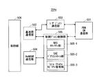
- FIG. 5 is a block diagram showing the configuration of the MME according to the present invention.
- FIG. 5 shows the configuration of the MME 204a included in the MME unit 204 shown in FIG.
- the PDN GW communication unit 501 transmits and receives data between the MME 204a and the PDN GW.
- the base station communication unit 502 performs data transmission / reception between the MME 204a and the base station 203 using the S1 interface.
- the data received from the PDN GW is user data
- the user data is passed from the PDN GW communication unit 501 to the base station communication unit 502 via the user plane communication unit 503 and to one or more base stations 203.
- Sent When the data received from the base station 203 is user data, the user data is passed from the base station communication unit 502 to the PDN GW communication unit 501 via the user plane communication unit 503 and transmitted to the PDN GW.
- control data is passed from the PDN GW communication unit 501 to the control plane control unit 505.
- control data is transferred from the base station communication unit 502 to the control plane control unit 505.
- the HeNBGW communication unit 504 is provided when the HeNBGW 205 exists, and performs data transmission / reception through an interface (IF) between the MME 204a and the HeNBGW 205 depending on the information type.
- the control data received from the HeNBGW communication unit 504 is passed from the HeNBGW communication unit 504 to the control plane control unit 505.
- the processing result in the control plane control unit 505 is transmitted to the PDN GW via the PDN GW communication unit 501.
- the result processed by the control plane control unit 505 is transmitted to one or more base stations 203 via the S1 interface via the base station communication unit 502, and to one or more HeNBGWs 205 via the HeNBGW communication unit 504. Sent.
- the control plane control unit 505 includes a NAS security unit 505-1, an SAE bearer control unit 505-2, an idle state mobility management unit 505-3, and the like, and performs overall processing for the control plane.
- the NAS security unit 505-1 performs security of a NAS (Non-Access Stratum) message.
- the SAE bearer control unit 505-2 performs management of SAE (System Architecture) Evolution bearers and the like.
- the idle state mobility management unit 505-3 performs mobility management in a standby state (idle state; also referred to as LTE-IDLE state or simply idle), generation and control of a paging signal in the standby state,
- the tracking area of one or a plurality of mobile terminals 202 is added, deleted, updated, searched, and tracking area list is managed.
- the MME 204a distributes the paging signal to one or a plurality of base stations 203. Further, the MME 204a performs mobility control (Mobility control) in a standby state (Idle State). The MME 204a manages a tracking area list when the mobile terminal is in a standby state and in an active state (Active State). The MME 204a starts a paging protocol by transmitting a paging message to a cell belonging to a tracking area (tracking area: TrackingTrackArea) where the UE is registered.
- the idle state mobility management unit 505-3 may perform CSG management, CSG-ID management, and whitelist management of the Home-eNB 206 connected to the MME 204a.
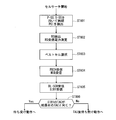
- FIG. 6 is a flowchart illustrating an outline from a cell search to a standby operation performed by a communication terminal (UE) in an LTE communication system.
- the communication terminal uses the first synchronization signal (P-SS) and the second synchronization signal (S-SS) transmitted from the neighboring base stations in step ST601, and performs slot timing, frame Synchronize timing.
- P-SS first synchronization signal
- S-SS second synchronization signal
- the P-SS and S-SS are collectively referred to as a synchronization signal (SS).
- SS synchronization signal
- a synchronization code corresponding to one-to-one is assigned to the PCI assigned to each cell.
- 504 patterns are under consideration. Synchronization is performed using the 504 PCIs, and the PCI of the synchronized cell is detected (specified).
- a cell-specific reference signal that is a reference signal (reference signal: RS) transmitted from the base station to each cell is detected for the synchronized cell.
- Measure the received power of RS Reference Signal Received Power: RSRP.
- RS Reference Signal Received Power
- RS Reference Signal
- a code corresponding to PCI one to one is used. By correlating with that code, it can be separated from other cells.
- deriving the RS code of the cell from the PCI specified in step ST601 it is possible to detect the RS and measure the received power of the RS.
- a cell having the best RS reception quality for example, a cell having the highest RS reception power, that is, the best cell is selected from one or more cells detected in step ST602.
- step ST604 the PBCH of the best cell is received and the BCCH that is broadcast information is obtained.
- MIB Master Information Block
- the MIB information includes, for example, DL (downlink) system bandwidth (also called transmission bandwidth setting (transmission bandwidth configuration: dl-bandwidth)), the number of transmission antennas, SFN (System frame number), and the like.
- SIB1 includes information related to access to the cell, information related to cell selection, and scheduling information of other SIBs (SIBk; an integer of k ⁇ 2).
- SIB1 includes a tracking area code (TrackingTrackArea Code: TAC).
- the communication terminal compares the TAC of SIB1 received in step ST605 with the TAC portion of the tracking area identifier (Tracking Area Identity: TAI) in the tracking area list already held by the communication terminal.
- the tracking area list is also referred to as a TAI list (TAI list).
- TAI is identification information for identifying a tracking area, and is composed of MCC (Mobile Country Code), MNC (Mobile Network Code), and TAC (Tracking Area Code).
- MCC Mobile Country Code
- MNC Mobile Network Code
- TAC Track Area Code
- MCC Mobile Country Code
- MNC Mobile Network Code
- TAC Track Area Code
- step ST606 If, as a result of the comparison in step ST606, the TAC received in step ST605 is the same as the TAC included in the tracking area list, the communication terminal enters a standby operation in the cell. In comparison, if the TAC received in step ST605 is not included in the tracking area list, the communication terminal passes through the cell to a core network (Core Network, EPC) including MME and the like, and TAU (Tracking Area Update). Request tracking area change to do
- EPC Core Network, EPC
- MME Mobile Management Entity
- TAU Track Area Update
- a device that constitutes a core network performs tracking based on the identification number (UE-ID, etc.) of the communication terminal sent from the communication terminal together with the TAU request signal. Update the area list.
- the core network side device transmits the updated tracking area list to the communication terminal.
- the communication terminal rewrites (updates) the TAC list held by the communication terminal based on the received tracking area list. Thereafter, the communication terminal enters a standby operation in the cell.
- a cell configured by an eNB has a relatively wide range of coverage.
- a cell is configured to cover a certain area with a relatively wide range of coverage of a plurality of cells configured by a plurality of eNBs.
- the cell configured by the eNB has a coverage that is narrower than the coverage of the cell configured by the conventional eNB. Therefore, in the same way as in the past, in order to cover a certain area, a larger number of eNBs having a smaller cell size are required as compared with the conventional eNB.
- a cell having a relatively large coverage such as a cell configured by a conventional eNB
- a macro cell an eNB configuring the macro cell
- a cell having a relatively small coverage such as a small cell
- an eNB configuring the small cell is referred to as a “small eNB”.
- the macro eNB may be a “wide area base station” described in Non-Patent Document 7, for example.
- the small eNB may be, for example, a low power node, a local area node, a hot spot, or the like.
- the small eNB is a pico eNB that constitutes a pico cell, a femto eNB that constitutes a femto cell, a HeNB, an RRH (Remote Radio Unit), an RRU (Remote Radio Unit), an RRE (Remote Radio Equipment), or an RN (Relay Node). There may be.
- the small eNB may be a “local area base station (Local (Base Station)” or “Home base station (Home Base Station)” described in Non-Patent Document 7.
- FIG. 7 is a diagram illustrating a concept of a cell configuration when a macro eNB and a small eNB coexist.
- a macro cell configured by a macro eNB has a relatively wide range of coverage 701.
- a small cell configured by a small eNB has a coverage 702 having a smaller range than a coverage 701 of a macro eNB (macro cell).
- the coverage of a cell configured by a certain eNB may be included in the coverage of a cell configured by another eNB.
- the small cell coverage 702 configured by the small eNB is included in the macro cell coverage 701 configured by the macro eNB. May be.
- a plurality of, for example, two small cell coverages 702 may be included in one macro cell coverage 701.
- a mobile terminal (UE) 703 is included in, for example, a small cell coverage 702 and performs communication via the small cell.
- the macro cell coverage 701 configured by the macro eNB and the small cell coverage 702 configured by the small eNB overlap in a complicated manner. Cases arise.
- a plurality of small cell coverages 702 configured by a plurality of small eNBs are configured in one macro cell coverage 701 configured by one macro eNB. Sometimes it happens.
- MIMO Multiple Input Multiple Output
- LTE and LTE-A a MIMO (Multiple Input Multiple Output) method is defined.
- MIMO is known as a technique for spatially multiplexing signals and transmitting a plurality of signals at the same frequency and the same timing, thereby improving the frequency utilization efficiency.
- There are various methods for calculating the transmission weight For example, a method of having a transmission weight table called a codebook in advance on the cell side and selecting a transmission weight from a codebook using feedback information from a communication terminal is adopted in LTE and LTE-A. Yes.
- the next generation communication method uses a method of measuring transmission path information between a cell and a communication terminal without using a codebook and calculating a transmission weight from the transmission path information each time. Is being considered.
- the transmission weight is obtained from CSI-RS (Channel Information Reference ⁇ Signal) received by the communication terminal or SRS (Sounding Reference Signal) received by the base station, and the transmission weight is calculated to obtain a more accurate transmission. It is possible to derive weights. This transmission weight is called precoding weight.
- the codebook selection method is determined by a one-to-one correspondence between cells and communication terminals. Therefore, the influence of interference on communication terminals being served by other cells becomes a problem.
- An example of the code book table is shown in Table 6.3.4.2.3-2 of Chapter 6.3.4 of Non-Patent Document 6. This table is for the case where the number of antenna ports of a cell is 4, and PMI (Precoding Matrix Indicator) and RI (Rank Indicator) are obtained based on CSI measured by the communication terminal.
- the transmission weight used for MIMO is determined by feeding back the obtained table to the cell side.
- a cell determines a codebook in consideration of an antenna port of only its own cell for UEs being served thereby.
- a cell to which the UE is not connected or not communicating is not considered. Therefore, in the case of a communication environment in which a plurality of cells are present, interference from a cell to which the UE is not connected or not performing communication is received.
- a transmission weight that is considered optimal for UEs being served by a cell is set in the same cell, strong interference may occur for UEs being served by another cell. Interference from other cells degrades communication quality and reduces communication speed. Moreover, the communication capacity as a system is also reduced. In the present embodiment, a method for solving such a problem is disclosed.
- MIMO performs MIMO using multiple cells.
- MIMO is performed by a plurality of cells and UEs being served by the cells.
- precoding using a plurality of cells is performed for a UE being served by a plurality of cells.
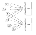
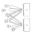
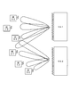
- SU-MIMO Single-User-MIMO
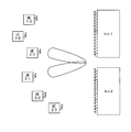
- FIG. 8 to 10 are diagrams showing the concept of a method for performing SU-MIMO using a plurality of cells. 8 to 10 show the case of two cells, cell 1 and cell 2.
- FIG. UE1-n (n is a natural number) is a UE being served by cell 1
- UE2-m (m is a natural number) is a UE being served by cell 2.
- MIMO is performed using cell 1 and cell 2.
- Each UE is allocated with a resource on a different frequency-time axis (hereinafter also referred to as “ft resource”). If the ft resources allocated to each UE are different, each UE may be allocated at the same time.
- FIG. 8 is a diagram illustrating an example of a configuration of a communication system in a case where SU-MIMO is performed on the UE 1-1 being served by the cell 1.
- precoding is performed in a plurality of layers using cell 1 and cell 2, and a beam is formed. A different stream for each layer is transmitted to the UE 1-1. Since the orthogonality is maintained between the beams formed for each layer by precoding, the UE 1-1 can receive a plurality of transmitted streams. By doing so, SU-MIMO is performed for UE 1-1 using cell 1 and cell 2.
- SU-MIMO is performed using cell 1 and cell 2.
- precoding is performed for the UE 1-1 in consideration of not only the cell 1 but also the transmission from the cell 2. Therefore, compared with the case where only the cell 1 performs SU-MIMO, it is possible to reduce interference from the cell 2 to the UE 1-1, and it is possible to reduce interference from the non-serving cell to the UE.
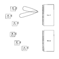
- FIG. 9 is a diagram illustrating an example of a configuration of a communication system in a case where SU-MIMO is performed for UEs 1-3 being served by cell 1.
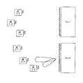
- FIG. 10 is a diagram illustrating an example of a configuration of a communication system in a case where SU-MIMO is performed for UE2-3 being served by cell2.
- the cell notifies the surrounding cells of the setting for measuring the transmission path information of the own cell (hereinafter also referred to as “CSI setting”). Further, the identifier of the own cell may be notified together with the CSI setting or included in the CSI setting. As a result, the cell that has received the CSI setting can recognize which cell has the CSI setting. By doing so, the cell can recognize the CSI setting of the surrounding cells.
- CSI setting for measuring the transmission path information of the own cell
- the CSI setting is signal information for measuring transmission path information for each cell, for example.
- the signal for measuring transmission path information for each cell may be a known series of signals.
- the information of the known series of signals for measurement of transmission path information for each cell may be used.
- the information may be information related to a reference signal (CSI-RS) for each antenna port for each cell.
- CSI-RS reference signal
- mapping information for measuring transmission path information for each cell may be included.
- the mapping information includes, for example, an insertion position such as frequency and time, an insertion period, transmission power, or an offset power value with respect to a reference transmission power value.
- the CSI setting may include information for measuring transmission path information (hereinafter sometimes referred to as “transmission path measurement information”).
- transmission path measurement information include the number of times of filtering, a filtering period, and a measurement period.
- the information for reporting the measurement result of the transmission path information may be included as the CSI setting.
- Examples of information for reporting the measurement result of the transmission path information include a report timing and a report cycle.
- Information on the transmission path estimation method may be included as the CSI setting.
- Information on an estimation value used for estimation may be included as information on a transmission path estimation method included as a CSI setting.
- the estimated value may be an instantaneous value. It is good also as an average value of the fixed period which filtered.
- Information on cross-correlation with the serving cell signal may be included as the CSI setting.
- Information on whether to use CSI-RS or SRS may be included as the CSI setting.
- Information on the cross-correlation with the serving cell signal obtained from the previous measurement result may be used instead of the estimated value of the transmission path.
- the transmission path estimation method is a method used to estimate transmission path information.
- the transmission path information is signal phase and amplitude distortion information given in the space between the cell and the communication terminal.
- the transmission path information is derived using a known sequence of signals, for example, reference signals such as CSI-RS and SRS.
- CSI-RS downlink
- SRS uplink
- the measurement method using CSI-RS is described in Patent Document 6.
- a measurement method using SRS is described in Non-Patent Document 13.
- a serving cell is a system cell that has established a radio link with a radio communication terminal.
- the serving cell signal is a general signal received from the serving cell.
- the signal at this time includes a data channel, a control channel, RS, and all signals. Unless otherwise stated, the signal indicates RS. 8 to 10, the serving cell of UE1-n (n is a natural number) is cell 1.
- the serving cell of UE2-m (m is a natural number) is cell 2.
- the information on the cross-correlation with the signal of the serving cell is information indicating the cross-correlation between the transmission path information between the serving cell and the communication terminal connected thereto and the transmission path information between the non-serving cell and the communication terminal.
- the information on the cross-correlation with the serving cell signal is the correlation between the transmission path information between the cell 1 and the UE 1-1 and the transmission path information between the cell 2 and the UE 1-1. Represents a value.
- cross-correlation information with the serving cell signal is received from the serving cell and received by the UE, and received from the non-serving cell and received by the UE. This corresponds to correlation information with the received vector of RS.
- the CSI setting should be notified using the X2 interface.
- the CSI setting may be notified to neighboring cells when the cell is installed or when the CSI setting is updated.
- CSI settings may be included in existing messages.
- the CSI setting may be included in the “X2 SETUP REQUEST” message and notified using the message at the time of cell installation.
- the CSI setting may be included in the “eNB Configuration Update” message and notified using the message when the CSI setting is updated.
- the CSI setting may be notified using the S1 interface.
- the CSI setting may be notified to neighboring cells when the cell is installed or when the CSI setting is updated.
- the CSI setting may be notified via a core network node, eg, MME.
- the CSI setting may be notified by being included in an existing message.
- the CSI setting may be notified by being included in, for example, an “S1 SETUP REQUEST” message, an “eNB Configuration Update” message, an “eNB Configuration Transfer” message, an “MME Direct Information Transfer” message, or the like.
- each cell perform CSI setting. Thereby, the setting according to the number of antenna ports of the own cell and the usage status of the resource becomes possible.
- the CSI setting of each cell may be performed by a node having a function of centrally controlling a plurality of cells.
- a node having a function of centrally controlling a plurality of cells is referred to as a “concentrator”.
- the eNB may have this function.
- the eNB becomes a concentrator.
- the MME may have a concentrator function.
- the S1 interface is used.
- the function may be provided in the base station, that is, in either the CU or the DU.
- the CU may have a part of the function and the DU may have another part.
- the DU may have this function.
- the CU may have this function. This makes it possible to perform MIMO using a plurality of cells even when the CU and DU are arranged separately.
- the concentrator When the concentrator performs CSI setting of each cell, the concentrator notifies the subordinate cell of the CSI setting of each cell.
- the identifier of each cell may be notified together with the CSI setting or included in the CSI setting. As a result, the cell that has received the CSI setting can recognize which cell has the CSI setting.
- the CSI setting of each cell may be performed by OAM (operation administration and maintenance).
- OAM operation administration and maintenance
- the OAM notifies the subordinate cell of the CSI setting for each cell.
- the identifier of each cell may be notified together with the CSI setting or included in the CSI setting. As a result, the cell that has received the CSI setting can recognize which cell has the CSI setting.
- the cell notifies the UE being served thereby of the CSI setting of the own cell.
- the cell notifies the UEs being served thereof of CSI settings of neighboring cells.
- the cell may broadcast the CSI setting as broadcast information.
- the CSI setting may be individually notified to the UE by dedicated signaling.
- a set of cells that can perform MIMO may be set.
- a cell pair capable of performing MIMO may be provided.
- a set of cells capable of performing MIMO or a pair of cells capable of performing MIMO is referred to as a MIMO cell.
- the MIMO cell may be determined by the OAM.
- the MIMO cell may be determined by the concentrator.
- the OAM or the concentrator notifies the MIMO cell of the identifier of the cell included in the MIMO cell. Thereby, each cell included in the MIMO cell can recognize which cell can perform MIMO.
- each cell included in MIMO can recognize a cell that notifies CSI setting.
- the cell that notifies the CSI setting may be limited to the cell that can perform MIMO and the own cell.
- a cell notifying the CSI setting may be limited to a MIMO cell. You may change the cell which can perform MIMO for every UE. By doing in this way, it becomes possible to reduce the signaling amount for the CSI setting performed between cells.
- the UE that has received the CSI setting of the serving cell and the CSI of the neighboring cells from the serving cell measures transmission path information using the CSI setting.
- the UE notifies the serving cell of the measurement result of the transmission path information.
- the signal for measuring the transmission path information is CSI-RS
- the UE notifies CSI as a measurement result.
- the transmission path information obtained from CSI-RS or SRS may be a complex number matrix having a product size of the number of transmission antenna ports of the corresponding cell and the number of reception antennas of the corresponding UE.
- RRC signaling may be used for notification of measurement results of transmission path information from the UE to the serving cell. Since retransmission control is performed, it is possible to transmit with a low error rate by using RRC signaling.
- an L1 / L2 control channel may be used.
- PUCCH may be used.
- transmission delay can be reduced. Therefore, the transmission path information measured by the UE can be notified to the serving cell at an early stage, and can be reflected in MIMO at an early stage.
- the serving cell can acquire the measurement result of the transmission path information of the own cell and the surrounding cells from the UE being served thereby.
- Different nodes may perform scheduling and precoding.
- the cell may notify the measurement result of the transmission path information from the UEs being served to both the node that performs scheduling and the node that performs precoding.
- the node that performs scheduling and precoding is a concentrator.
- the measurement result of the transmission path information is notified between the eNBs.
- An X2 interface may be used for notification of measurement results of transmission path information.
- the measurement result of the transmission path information may be notified using the S1 interface.
- You may notify the measurement result of transmission-line information via a core network node, for example, MME.
- the measurement result of the transmission path information may be notified by being included in an existing message of the X2 interface or the S1 interface.
- the method disclosed in the CSI setting notification method may be applied. As a result, the same effect as the method disclosed in the CSI setting notification method can be obtained.
- the concentrator that has acquired the measurement results of the transmission cell information of the serving cell of the UE being served by the own cell and the surrounding cells from the cell being served by the cell performs scheduling of all UEs being served by the plurality of cells in cooperation with MIMO. Scheduling includes ft resource allocation and MCS (Modulation and Coding Scheme). In SU-MIMO, one UE is scheduled for one ft resource. Execution of SU-MIMO can be facilitated by the concentrator scheduling all UEs.
- the concentrator that performed scheduling of all UEs under a plurality of cells that perform MIMO cooperatively performs precoding of all UEs under the control of a plurality of cells that perform MIMO cooperatively.
- the precoding weight is derived using the measurement result of the UE transmission path information obtained from the subordinate cell.
- the concentrator notifies the scheduling result to each cell that performs MIMO in cooperation. At this time, the scheduling information of each cell may be notified.
- the concentrator notifies the result of precoding to each cell that performs MIMO cooperatively. At this time, the precoding information regarding each cell is notified.
- scheduling information or precoding information is notified between eNBs.
- An X2 interface may be used for notification of scheduling information or precoding information.
- scheduling information or precoding information may be notified using the S1 interface.
- You may notify scheduling information or precoding information via a core network node, for example, MME.
- the existing message of the X2 interface or the S1 interface may be notified by including scheduling information or precoding information.
- the method disclosed in the CSI setting notification method may be applied. As a result, the same effect as the method disclosed in the CSI setting notification method can be obtained.
- Each cell performs scheduling for all UEs using the scheduling information notified from the concentrator.
- Each cell performs MIMO setting for all UEs using the precoding information notified from the concentrator.
- the MIMO setting may include precoding weight calculation by the concentrator based on CSI measured in each target UE.
- the MIMO setting may include information associating the transmission data stream with the calculated precoding weight.
- the MIMO setting may include information associating transmission data with a transmission target UE.
- the MIMO setting may include information obtained by multiplying the precoding weight and the transmission data.
- the setting of MIMO may include setting of the modulation scheme of the transmission data stream.
- the MIMO setting may include a coding rate.
- the setting of the MIMO may include setting of the number of transmission streams by rank adaptation.
- Rank adaptation is the number of transmittable data streams calculated from transmission path information.
- the cell performs DL transmission in order to perform SU-MIMO transmission to all UEs.
- the cell performs DL transmission to a UE being served thereby.
- the cell does not perform DL transmission to non-participating UEs.
- the cell enables SU-MIMO using a plurality of cells by performing DL transmission also to a UE being served thereby. By doing so, the UE can reduce interference from non-serving cells.
- the cell notifies the UEs being served thereof scheduling information of the downlink physical channel (PDSCH) for DL transmission.
- PDSCH downlink physical channel
- An L1 / L2 control channel may be used for notification of the scheduling information.
- PDCCH or EPDCCH may be used.
- a cell transmits a UE-specific reference signal (UE ⁇ Specific Reference Signal) such as DM-RS to a downlink physical channel (PDSCH) for DL transmission to a non-subordinate UE. ) Is recommended.
- UE ⁇ Specific Reference Signal UE ⁇ Specific Reference Signal
- PDSCH downlink physical channel
- CRS reference signal
- the UE can receive the PDSCH from the non-serving cell.
- the serving cell may determine the UE-specific reference signal.
- the serving cell notifies the UE of information related to UE-specific reference signals.
- RRC signaling may be used for notification of information related to UE-specific reference signals. Since the information related to the UE-specific reference signal is UE-specific information, it may be notified using dedicated signaling.
- notification may be made using MAC signaling. Or you may notify using a L1 / L2 control channel. This makes it possible to apply dynamically and with little delay.
- the UE-specific reference signal may be determined by the concentrator.
- the concentrator notifies the UE of information related to the UE-specific reference signal via the serving cell.
- the concentrator determines the UE-specific reference signal, the UE-specific reference signal can be allocated in a plurality of cells without duplication. As a result, the UE can be prevented from receiving the PDSCH transmitted to other UEs by mistake.
- the serving cell notifies the UE being served thereof of the cell identifier of the non-serving cell.
- the UE can receive a signal from a non-serving cell using the identifier.
- the notification may be omitted.
- the UE may regard the identifier of the non-serving cell as the same as the identifier of the serving cell.
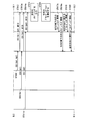
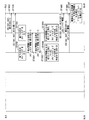
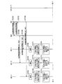
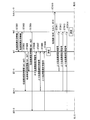
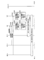
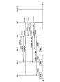
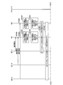
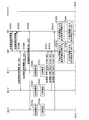
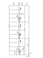
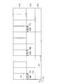
- FIG. 11 and FIG. 12 are diagrams illustrating an example of a sequence related to a method for performing SU-MIMO using a plurality of cells.
- 11 and 12 are connected at the position of the boundary line BL1.
- 11 and 12 show a case where SU-MIMO is performed using cell 1 and cell 2 as an example.
- 11 and 12 show the processing of UE 1-1 and UE 1-3 being served by cell 1 and UE 2-3 being served by cell 2.
- step ST901 the cell 2 notifies the cell 1 which is a neighboring cell of the CSI setting of the own cell.
- step ST902 the cell 1 notifies the cell 2 which is a neighboring cell of the CSI setting of the own cell.
- step ST903 the cell 1 notifies the UE 1-1 being a UE being served thereof of the CSI setting of the own cell and the CSI setting of the cell 2.
- Step ST904 the cell 1 notifies the UE 1-3, which is a UE being served, of the CSI setting of the own cell and the CSI setting of the cell 2.
- Step ST905 the cell 2 notifies the UE 2-3, which is a UE being served, of the CSI setting of the own cell and the CSI setting of the cell 1.
- the UE 2-3, UE 1-3, and UE 1-1 that have received the CSI settings of the serving cell and the neighboring cells measure the transmission path information using the CSI settings in Step ST906, Step ST907, and Step ST908.
- the UE measures transmission path information not only for the serving cell but also for neighboring cells, in other words, for non-serving cells.
- Step ST909 the UE 1-1 notifies the measurement result of the transmission path information of the cell 1 and the cell 2 to the cell 1 that is the serving cell.
- Step ST910 the UE 1-3 notifies the cell 1 that is the serving cell of the measurement result of the transmission path information of the cell 1 and the cell 2.
- step ST911 the UE 2-3 notifies the measurement result of the transmission path information of the cell 1 and the cell 2 to the cell 2 that is the serving cell.
- Step ST912 the cell 1 notifies the concentrator of the measurement results of the transmission path information of the cell 1 and the cell 2 acquired from the UE 1-1 being served together with the UE ID that is the identifier of each UE.
- step ST913 the cell 1 notifies the concentrator of the measurement results of the transmission path information of the cell 1 and the cell 2 acquired from the UEs 1-3 being served together with the UE ID that is the identifier of each UE.
- step ST914 the cell 2 notifies the concentrator of the measurement results of the transmission path information of the cell 1 and the cell 2 acquired from the UEs 2-3 being served together with the UE ID that is the UE identifier.
- step ST912 step ST913, and step ST914, the concentrator that has acquired the measurement results of the transmission path information of cell 1 and cell 2 from the UEs being served by cell 1 and cell 2 performs the process of step ST915.
- step ST915 the concentrator performs scheduling of all UEs being served by cell 1 and cell 2.
- step ST912 step ST913, and step ST914, the concentrator that has acquired the measurement results of the transmission path information of cell 1 and cell 2 from the UEs being served by cell 1 and cell 2 performs the process of step ST916.
- Step ST916 the concentrator derives precoding weights of all UEs being served by the cell 1 and the cell 2.
- step ST917 the concentrator notifies cell 2 of scheduling information related to cell 2 of all UEs being served by cell 1 and cell 2.
- the concentrator in step ST918 of FIG. 12, notifies the cell 1 of scheduling information related to the cell 1 of all UEs being served by the cell 1 and the cell 2.
- step ST919 the concentrator notifies cell 2 of precoding information related to cell 2 of all UEs being served by cell 1 and cell 2.
- step ST920 the concentrator notifies cell 1 of precoding information related to cell 1 of all UEs being served by cell 1 and cell 2.
- Step ST921 the cell 1 performs scheduling for all UEs using the scheduling information received in Step ST918.
- Step ST922 the cell 2 performs scheduling for all UEs using the scheduling information received in Step ST917.
- Step ST923 the cell 1 performs MIMO setting for all UEs using the precoding information received in Step ST920.
- Step ST924 the cell 2 performs MIMO setting for all UEs using the precoding information received in Step ST919.
- Step ST925 the cell 2 performs SU-MIMO transmission to the UE 1-1 according to the scheduling performed in Step ST921 and the MIMO setting performed in Step ST923.
- Step ST926 the cell 2 performs SU-MIMO transmission to the UE 1-3 according to the scheduling performed in Step ST921 and the MIMO setting performed in Step ST923.
- Step ST927 the cell 2 performs SU-MIMO transmission to the UE 2-3 according to the scheduling performed in Step ST921 and the MIMO setting performed in Step ST923.
- step ST928 cell 1 performs SU-MIMO transmission to UE 1-1 according to the scheduling performed in step ST922 and the MIMO setting performed in step ST924.
- Step ST929 the cell 1 performs SU-MIMO transmission to the UE 1-3 according to the scheduling performed in Step ST922 and the MIMO setting performed in Step ST924.
- Step ST930 the cell 1 performs SU-MIMO transmission to the UE 2-3 according to the scheduling performed in Step ST922 and the MIMO setting performed in Step ST924.
- UE 1-1, UE 1-3, and UE 2-3 perform SU-MIMO transmission by a plurality of cells, here, cell 1 and cell 2.
- SU-MIMO can be performed by a plurality of cells and UEs being served by the cells.
- precoding using a plurality of cells can be performed for a UE being served by a plurality of cells.
- Embodiment 1 Modification 1 The method for performing SU-MIMO considering a plurality of cells is disclosed in the first embodiment.
- Embodiment 1 only discloses a SU-MIMO method taking into account a plurality of cells, and does not mention selection of a communication terminal (UE) that is a target of SU-MIMO. Efficient selection of target UEs is necessary to obtain a sufficient MIMO effect using a plurality of cells.
- the UE when the UE is not selected, the amount of information notified from the UE to the cell becomes enormous.
- the UE must measure the CSI of other cells that are not serving cells as well as the serving cell and report the results. Therefore, the following five (1) to (5) are problems.
- the UE determines from the CSI measurement result whether there is a cell causing interference. The UE does not notify the cell of the CSI measurement result of the cell where interference is not a problem.
- Uplink ft resources can be reduced by not notifying the cell of the CSI measurement result.
- the cell does not notify the concentrator of the CSI measurement result.
- the concentrator derives a precoding weight using a predetermined value.
- a predetermined value for example, a value of amplitude 0 may be used. By excluding it from the calculation, it may not be taken into account when deriving the precoding weight.
- the schedule for the UE being served by each cell other than the UE that is subject to interference is not performed by transmitting information to the concentrator and performing processing. You may process independently in each cell.
- SU-MIMO is performed in cooperation with a plurality of cells for UE 1-1 under the control of the own cell where interference is a problem, and for UEs where interference of other cells is not a problem, in each cell Perform normal SU-MIMO.
- UE needs to identify cells where interference is not a problem.
- Information that is measured on the UE side can also be used as a method for identifying a cell in which interference is not a problem.
- downlink RSRP Reference Signal Received Power
- RSRQ Reference Signal Received Quality
- signal-to-interference noise power ratio Signal-to-interference noise power ratio (Signal Signal to Interference Noise plus Noise).
- SINR Signal-to-interference noise power ratio
- the predetermined threshold value may be statically determined in advance or may be notified from the serving cell to the UE. Further, the predetermined threshold value may use a broadcast channel or may be signaled individually. When it is determined that interference is not a problem, information without interference may be transmitted from the UE.
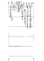
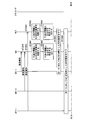
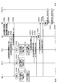
- FIGS. 13 to 15 are diagrams showing other examples of sequences relating to a method of performing SU-MIMO using a plurality of cells.
- 13 and 14 are connected at the position of the boundary line BL2.
- 14 and 15 are connected at the position of the boundary line BL3.
- FIGS. 13 to 15 show a case where SU-MIMO is performed using the cell 1 and the cell 2.
- 13 to 15 show the processing of UE 1-1 and UE 1-3 being served by cell 1 and UE 2-3 being served by cell 2.
- the sequence shown in FIGS. 13 to 15 includes the same steps as the sequences shown in FIGS. 11 and 12, and the same steps are denoted by the same step numbers and the common description is omitted.
- step ST1001 After performing the processing of step ST901 to step ST908, in step ST1001, UE2-3 determines from the measurement result of step ST906 whether there is a cell in which interference does not matter.
- step ST1002 UE1-3 determines the presence / absence of a cell in which interference does not matter from the measurement result in step ST907.
- step ST1003 the UE 1-1 determines the presence / absence of a cell in which interference is not a problem from the measurement result in step ST908.
- step ST1004 the UE 2-3 identifies the cell in which interference does not become a problem as the cell 1.
- step ST1005 the UE 1-3 identifies a cell in which interference is not a problem as the cell 2.
- step ST1006 the UE 1-1 identifies that there is no cell in which interference does not cause a problem.
- step ST910a the UE1-3 notifies the cell 1 which is the serving cell of the measurement result of the transmission path information of the cell1.
- Step ST911a the UE 2-3 notifies the measurement result of the transmission path information of the cell 2 to the cell 2 that is the serving cell.
- Step ST913a the cell 1 notifies the concentrator of the measurement result of the transmission path information of the cell 1 acquired from the UEs 1-3 being served, together with the UE ID that is the identifier of each UE.
- step ST914a the cell 2 notifies the concentrator of the measurement result of the transmission path information of the cell 2 acquired from the UEs 2-3 being served together with the UE ID that is the UE identifier.
- step ST915 and step ST916 are performed.
- step ST917a the concentrator notifies cell 2 of scheduling information of UEs being served by cell 2.
- step ST918a the concentrator notifies cell 1 of scheduling information of UEs being served by cell 1.
- step ST919 and step ST920 processing of step ST919 and step ST920 is performed.
- the CSI measured by the UE is notified in order from the cell to the concentrator, and the scheduling of all UEs being served by a plurality of cells and the derivation of the precoding weight are performed by the concentrator.
- the derived precoding weight is notified to each cell.
- Step ST1007 in FIG. 15 the cell 1 performs scheduling of UEs being served thereby based on the scheduling information notified from the concentrator in Step ST918.
- step ST1008 the cell 2 schedules the UEs being served based on the scheduling information notified from the concentrator in step ST917.
- step ST923 and step ST924 are performed.
- step ST925 to step ST930 similarly to FIG. 12, MIMO transmission is performed to UEs being served thereby.
- Embodiment 1 Modification 2 The processing for performing SU-MIMO in consideration of a plurality of cells requires the precoding processing including all UEs being served by the plurality of cells, and the processing becomes complicated. This causes an increase in power consumption of the base station, an increase in circuit scale, and an increase in control delay. In addition, since a large number of UEs are targeted, there arises a problem that scheduling becomes complicated.
- the method of performing SU-MIMO considering a plurality of cells is disclosed in the first modification of the first embodiment.
- the UE selects the communication terminal that is the target of SU-MIMO.
- a method for selecting a UE in which interference causes a problem in a cell based on information from the UE is disclosed.
- By selecting the cell instead of the UE it is possible to reduce the computational load on the UE.
- the amount of information used for notification between the cell and the concentrator can be reduced.
- a method for determining a UE that is a target of SU-MIMO there are a method in which a cell judges, a method in which a concentrator or a higher-order node judges.
- a method for determining a UE that is a target of SU-MIMO a method may be used in which downlink CSI-RS is used to measure and judge reception quality using RSRP, RSRQ, SINR, or the like. At this time, if the measured value is smaller than a predetermined threshold value, it may be determined that interference does not cause a problem.
- it may be determined from the eigenvalue corresponding to each UE obtained from the transmission path information.
- it may be determined from the measurement result of CSI-RS (NonNZero Power) from the UE. Or based on the measurement result of CSI-IM from UE, you may obtain
- CSI-RS NonNZero Power
- information without interference may be transmitted from the UE.
- uplink SRS may be measured in a serving cell and a non-serving cell, and it may be determined by measuring which cell is interfering with which UE.
- the UE on which interference is a problem may be determined on the cell side or the concentrator side.
- the predetermined threshold value may be statically determined in advance or may be notified to the cell from the concentrator.
- the cell may notify the concentrator that there is no interference.
- FIG. 16 to 18 are diagrams showing the concept of a method for performing SU-MIMO limited to UEs where interference is a problem.
- FIG. 16 illustrates a case where SU-MIMO is performed on UE 1-1 in cooperation with cell 1 and cell 2 after limiting UEs to be subjected to SU-MIMO.
- FIG. 17 shows a case in which SU-MIMO is performed only for UEs in the own cell in cell 1.
- FIG. 18 illustrates a case where the cell 2 performs SU-MIMO only for UEs in the own cell.
- FIGS. 19 to 21 are diagrams showing another example of a sequence related to a method of performing SU-MIMO using a plurality of cells.
- 19 and 20 are connected at the position of the boundary line BL4.
- 20 and 21 are connected at the position of the boundary line BL5.
- FIGS. 19 to 21 show a case where SU-MIMO is performed using the cell 1 and the cell 2 as an example.
- FIGS. 19 to 21 show processing of UE 1-1 and UE 1-3 being served by cell 1 and UE 2-3 being served by cell 2.
- the sequence shown in FIGS. 19 to 21 includes the same steps as the sequences shown in FIGS. 11 and 12, and the same steps are denoted by the same step numbers and the common description is omitted.
- the point different from the first embodiment described above is that after the CSI measurement in the UE, it is determined whether there is a UE that causes interference in the cell.
- the cell 1 determines whether there is a UE having a problem of interference.
- transmission path information broadcast from the UE may be used.
- RSRP, RSRQ, or SINR may be used.
- step ST1202 the cell 2 determines whether there is a UE having a problem of interference.
- step ST1203 the cell 1 identifies the UE whose interference is a problem as the UE 1-1.
- step ST1204 the cell 2 specifies that there is no UE in which interference is a problem.
- step ST1205 of FIG. 20 cell 1 informs the concentrator of the CSI and the identified UE2-1 UEID.
- step ST1206 the concentrator performs scheduling of UE in which interference is a problem.
- step ST1207 the concentrator derives a precoding weight of the UE in which interference is a problem.
- step ST1208 the concentrator notifies the cell 2 of the schedule information of the UE in which interference is a problem.
- step ST1209 the concentrator notifies the cell 1 of the schedule information of the UE in which interference is a problem.
- step ST1210 the concentrator notifies the cell 2 of precoding information related to the cell 2 of the UE in which interference is a problem.
- step ST1211 the concentrator notifies the cell 1 of precoding information related to the cell 1 of the UE in which interference is a problem.
- step ST1212 the cell 1 performs scheduling of the UE in which interference is a problem.
- Step ST1213 the cell 2 performs scheduling of the UE in which interference is a problem.
- Step ST1214 the cell 1 performs scheduling of other UEs being served thereby.
- Step ST1215 the cell 2 performs scheduling of other UEs being served thereby.
- SU-MIMO is performed independently in each cell. At this time, scheduling is performed in consideration of the need to use different RBs for performing MIMO in a plurality of cells and MIMO in a single cell.
- Step ST1216 the cell 1 derives the precoding weight of the UE being served by the cell 1.
- Step ST1217 the cell 2 derives the precoding of the UE being served by the cell 2.
- Step ST1218 the cell 1 performs the MIMO setting of the UE having a problem of interference with the UE being served thereby.
- Step ST1219 the cell 2 performs the MIMO setting of the UE that causes interference with the UE being served thereby.
- MIMO can be performed in consideration of a plurality of cells only for UEs where interference is a problem. It is possible to limit the precoding process only to UEs where interference is a problem. Therefore, it is possible to reduce the complexity of the precoding process. It is possible to reduce the power consumption of the base station, the circuit scale, and the control delay.
- Embodiment 1 Modification 3 In prior art MIMO, the cell performs MIMO by determining a codebook for the UE in consideration of only the antenna port of the own cell. At this time, cells to which the UE is not connected or not communicating are not considered. Therefore, in the case of a communication environment in which a plurality of cells are present, interference from a cell to which the UE is not connected or not performing communication is received.
- MIMO is performed by setting a transmission weight that seems to be optimal for UEs being served by a cell, which may cause strong interference to UEs being served by another cell. is there.
- communication quality deteriorates due to interference from other cells, and the communication speed is reduced.
- the communication capacity is reduced as a system.
- the purpose of this modification is to solve the above problems and suppress degradation of communication quality, communication speed and communication capacity due to interference from other cells in a communication environment where a plurality of cells exist. It is to provide a communication system that can.
- This modification discloses a modification of the first embodiment in which SU-MIMO is performed in consideration of a plurality of cells.
- MIMO from a plurality of cells is not considered by SU-MIMO limited to one UE, but is assumed to be MU-MIMO considering a plurality of users.
- FIG. 22 is a diagram illustrating a concept of a method for performing MU-MIMO on UEs being served by considering a plurality of cells.
- a plurality of cells of cell 1 and cell 2 perform MU-MIMO in cooperation.
- a method similar to that in the case of SU-MIMO in the first embodiment may be applied.
- Cell 2 is a resource scheduled by cell 1 and transmits a PDSCH using a UE-specific reference signal.
- cell 1 transmits the PDSCH using the UE-specific reference signal with the resources scheduled by cell 2.
- the UE receives the PDSCH using the UE-specific reference signal with resources scheduled by the serving cell.
- the codebook When using the codebook, it is necessary to notify the UE of PCI from both the cell 1 serving as a serving cell and the cell 2 serving as a non-serving cell.
- the UE receives the PDSCH by knowing the transmission weight used for precoding using the PCI of the cell 1 and the cell 2.
- FIG. 23 and FIG. 24 are diagrams illustrating an example of a sequence related to a method of performing MU-MIMO using a plurality of cells including a UE in which interference is a problem.
- FIG. 23 and FIG. 24 are connected at the position of the boundary line BL6.
- the sequence shown in FIGS. 23 and 24 includes the same steps as the sequences shown in FIGS. 11 and 12, and FIGS. 13 to 15. Therefore, the same steps are denoted by the same step numbers and are common. Description to be omitted is omitted.
- step ST901 to step ST915 is performed in the same manner as in FIG.
- step ST1401 the concentrator derives a precoding weight of the UE that performs MU-MIMO.
- the concentrator notifies the cell 2 of precoding information related to the cell 2 of the UE performing MU-MIMO.
- step ST1403 the concentrator notifies cell 1 of precoding information related to cell 1 of the UE performing MU-MIMO.
- Step ST1404 the cell 1 performs scheduling of UEs being served by the cell 1.
- Step ST1405 the cell 2 performs scheduling of UEs being served by the cell 2.
- Step ST1406 the cell 1 performs the MIMO setting of the UE that performs MU-MIMO.
- Step ST1407 the cell 2 performs the MIMO setting of the UE that performs MU-MIMO.
- MU-MIMO considering a plurality of cells can be performed by using precoding information derived for MU-MIMO.
- MU-MIMO can be performed by precoding using a plurality of cells.
- By performing MU-MIMO in consideration of transmission path information from other cells than the serving cell it is possible to reduce interference from other cells.
- the communication quality can be improved.
- the communication capacity as a system can be improved. In particular, in a situation where there are a large number of small cells and interference between cells increases, a significant effect can be obtained.
- Embodiment 1 Modification 4 In the process of performing MU-MIMO considering a plurality of cells, a precoding process including all UEs being served by the plurality of cells must be performed, and the process becomes complicated. This leads to an increase in power consumption of the base station, an increase in circuit scale, and an increase in control delay. Moreover, since it targets many UE, there exists a problem that scheduling becomes complicated.
- This modification discloses a modification of the first embodiment in which MU-MIMO is performed in consideration of a plurality of cells. This modification discloses a case where MU-MIMO is performed in consideration of a plurality of users.
- the serving cell can perform MU-MIMO considering only its own cell. Therefore, it is possible to reduce the number of UEs to be subjected to MIMO performed in a plurality of cells.
- the serving cell For UEs where interference is not a problem, the serving cell performs DL transmission considering only its own cell. MU-MIMO may be performed. At this time, precoding is performed considering only the own cell, not a plurality of cells.
- the method for determining a UE to be subjected to MU-MIMO by a plurality of cells is the same as that in the second modification of the first embodiment.
- allocation is performed on the same ft resource in MIMO that considers a plurality of cells and MIMO that considers only the own cell, it is difficult to maintain orthogonality with each other, and therefore different ft resources are used.
- MU-MIMO When there are multiple UEs being served by a cell, MU-MIMO is performed. However, when there is only one UE being served by a cell, there is no need to perform MU-MIMO, so MU-MIMO to SU-MIMO is not necessary. Switch.
- Scheduling after UEs to be subjected to MU-MIMO by a plurality of cells is performed for UEs being served by each cell.
- Each cell notifies the concentrator of scheduling information of the target UE.
- information may be sent to the UE via the concentrator.
- the cooperative cell that has received the scheduling information notifies the concentrator of the UE that is scheduling using the same ft resource.
- CSI is also notified.
- the concentrator performs MU-MIMO with the UE using the same ft resource.
- the base station In determining a UE to be subjected to MU-MIMO, when the base station receives UE capability information and determines that the UE is equipped with an interference cancellation algorithm, the UE performs the MU-MIMO from the target to perform MU-MIMO. May be removed.
- FIG. 25 to FIG. 27 are diagrams illustrating an example of a concept of a method for performing MU-MIMO using a plurality of cells limited to UEs in which interference is a problem.
- FIG. 25 shows a case where MU-MIMO is performed on UE 1-1 and UE 2-1 in cooperation with cell 1 and cell 2 after limiting UEs to be subjected to MU-MIMO.
- FIG. 26 illustrates a case where the cell 1 independently performs MU-MIMO on the UE1-2 and UE1-3.
- FIG. 27 illustrates a case where the cell 2 independently performs MU-MIMO on the UE 2-2 and the UE 2-3.
- FIGS. 28 to 30 are diagrams illustrating an example of a sequence related to a method of performing MU-MIMO using a plurality of cells limited to a UE in which interference is a problem.
- FIG. 28 and FIG. 29 are connected at the position of the boundary line BL7.
- FIG. 29 and FIG. 30 are connected at the position of the boundary line BL8.
- the sequence shown in FIGS. 28 to 30 includes the same steps as the sequences shown in FIGS. 11 and 12, and FIGS. 19 to 21, and therefore the same steps are denoted by the same step numbers and are common. Description to be omitted is omitted.
- step ST1601 the cell 2 identifies the UE having the problem of interference as the UE 2-1.
- step ST1602 cell 2 informs the concentrator of the CSI and the UE ID of the identified UE.
- the difference between the present modification and the third modification of the first embodiment is that the third modification of the first embodiment is SU-MIMO and the present modification is MU-MIMO.
- the third modification of the first embodiment is SU-MIMO
- the present modification is MU-MIMO.
- MU-MIMO when there is a degree of freedom in transmission antennas, it is possible to take into account the maximum number of transmission antennas.
- precoding processing that takes into account multiple cells that are heavy in processing is limited to UEs that are subject to interference. Can be done. Therefore, it is possible to reduce the complexity of the precoding process. Further, it becomes possible to reduce the power consumption of the base station, the circuit scale, and the control delay.
- the transmission rate of the system can be improved by performing MU-MIMO considering a plurality of cells.
- Embodiment 1 Modification 5 In the process of performing MU-MIMO considering a plurality of cells, a precoding process including all UEs being served by the plurality of cells must be performed, and the process becomes complicated. This leads to an increase in power consumption of the base station, an increase in circuit scale, and an increase in control delay. Moreover, since it targets many UE, there exists a problem that scheduling becomes complicated.
- the processing amount can be reduced.
- the serving cell For UEs where interference from non-serving cells is not a problem, the serving cell performs MU-MIMO considering only its own cell.
- the UE itself may determine whether interference is a problem.
- the concentrator may notify the concentrator of CSI and UEID, and the concentrator may make a determination.
- the target UE determination method is the same as in Modification 2 of Embodiment 1, in which each cell is notified of the CSI measured by the UE, and based on the CSI, the UE for which interference from non-serving cells is a problem is determined. Identify.
- Each cell is notified of CSI, and uses the CSI to schedule UEs being served thereby. At this time, since no concentrator is used, processing delay is reduced, and each cell can be flexibly scheduled.
- the concentrator performs only the precoding weight calculation considering a plurality of cells.
- FIG. 31 and FIG. 32 are diagrams illustrating another example of the concept of the method of performing MU-MIMO using a plurality of cells limited to UEs in which interference is a problem.
- FIG. 31 shows a case where MU-MIMO is performed on UE 1-1 and UE2-2 in cooperation with cell 1 and cell 2 after limiting UEs to be subjected to MU-MIMO.
- FIG. 32 shows a case where MU-MIMO is performed on UE 2-1 and UE 1-3 in cooperation with cell 1 and cell 2, respectively.
- FIGS. 33 to 35 are diagrams showing another example of a sequence related to a method of performing MU-MIMO using a plurality of cells limited to UEs where interference is a problem.
- 33 and FIG. 34 are connected at the position of the boundary line BL9.
- 34 and FIG. 35 are connected at the position of the boundary line BL10.
- the sequence shown in FIGS. 33 to 35 includes the same steps as the sequences shown in FIGS. 11 and 12, and FIGS. 19 to 21, and therefore the same steps are denoted by the same step numbers and are common. Description to be omitted is omitted.
- each cell performs scheduling for UEs being served thereby and performs processing without going through an upper layer such as a concentrator.
- Step ST1701 the cell 1 performs scheduling of UEs being served by the cell 1.
- step ST1702 the cell 2 schedules UEs being served by the cell 2.
- Step ST1801 the cell 1 notifies the cell 2 of the schedule information of the UE in which the interference is a problem and the UE ID of the identified UE 1-1.
- Step ST1802 the cell 2 notifies the cell 1 of the schedule information of the UE in which the interference is a problem and the identified UE ID of the UE 2-1.
- step ST1803 the cell 1 identifies UE1-3 that is scheduling to the same resource as the UE2-1 that causes interference.
- step ST1804 the cell 2 specifies the UE 2-2 that is scheduling to the same resource as the UE 1-1 in which interference is a problem.
- step ST1805 the cell 2 notifies the concentrator of the CSI, the identified UE ID of the UE 2-2, and scheduling information.
- step ST1806 the cell 1 notifies the concentrator of the CSI, the UEID of the identified UE1-3, and scheduling information.
- step ST1807 the concentrator derives a precoding weight of the UE in which interference is a problem in consideration of a plurality of cells.
- step ST1808 the concentrator notifies the cell 2 of precoding information related to the cell 2 of the UE that uses the same resource as the UE in which interference is a problem.
- step ST1809 the concentrator notifies the cell 1 of precoding information related to the cell 1 of the UE that uses the same resource as the UE in which interference is a problem.
- Step ST1810 the cell 1 derives precoding weights of other UEs being served by the cell 1.
- step ST1811 cell 2 derives precoding weights of other UEs being served by cell 2.
- Step ST1812 the cell 1 performs the MIMO setting of the UE in which interference is a problem with the UE being served thereby.
- Step ST1813 the cell 2 performs the MIMO setting of the UE that causes interference with the UE being served thereby.
- each cell can perform scheduling of UEs being served thereby. Since each cell makes an independent determination, scheduling can be performed flexibly according to the condition of the transmission path.
- Embodiment 1 Modification 6 the cell estimates uplink transmission path information from a known signal, for example, SRS.
- the uplink and downlink have the same frequency as in time division duplex (TDD)
- the uplink transmission line is utilized by utilizing the duality of the uplink and downlink transmission line characteristics.
- downlink transmission path information is estimated.
- the method of estimating downlink transmission path information in this way (hereinafter sometimes referred to as “transmission path estimation method”) is particularly effective when uplink transmission and downlink transmission are TDD.
- transmission path estimation method the transmission path estimation method of the present modification will be specifically described.
- the serving cell notifies the UEs being served thereof of information for measuring the transmission path of the own cell.
- the serving cell notifies UEs being served thereof of transmission path measurement information for cells that perform MIMO cooperatively. For example, when the serving cell is cell 1 and the cell that performs MIMO cooperatively is cell 2, cell 1 transmits information for transmission path measurement of cell 1 that is its own cell and transmission of cell 2 to its UE. Notification of road measurement information.
- the serving cell can easily estimate the transmission path information by adjusting the UE schedule. For example, the serving cell adjusts the transmission timing of each UE so that the SRS of each UE does not have the same frequency and the same timing. Further, when the SRS is a signal that can be separated by CDM (Code Division Multiplex), the serving cell may adjust the schedule so that a plurality of UEs that can be separated simultaneously transmit SRS.
- CDM Code Division Multiplex
- the UE transmits the SRS to the cell 1 and the cell 2 based on the cell ID, scheduling information, and synchronization information obtained from the transmission path measurement information according to the schedule notified from the serving cell.
- the cell ID is cell identification information.
- the UE may transmit a different cell-specific sounding reference signal (Cell specific Sounding Reference Signal) for each cell to be transmitted. If the transmission timing to the cell 1 and the transmission timing to the cell 2 are different, the known signal transmitted by the UE may be unique to the UE. In this case, the known signal transmitted by the UE may be a UE-specific sounding reference signal (UE-specific Sounding Reference Signal) that is different for each UE.
- Cell specific Sounding Reference Signal Cell specific Sounding Reference Signal
- 36 to 38 are diagrams showing an example of a sequence related to a method for performing SU-MIMO using the transmission path estimation method according to the sixth modification of the first embodiment of the present invention.
- 36 and FIG. 37 are connected at the position of the boundary line BL11.
- FIG. 37 and FIG. 38 are connected at the position of the boundary line BL12.
- 36 to 38 show a sequence in the case where SU-MIMO is performed using a plurality of cells, specifically, cell 1 and cell 2.
- 36 to 38 show the processing of UE1-1 and UE1-3 being served by cell 1 and the processing of UE2-3 being served by cell2.
- step ST2701 the cell 2 notifies the cell 1 of the transmission path measurement information.
- step ST2702 the cell 1 notifies the cell 2 of the transmission path measurement information.
- Step ST2703 the cell 1 notifies the UE 1-3, which is a UE being served, of the transmission path measurement information of the cell 1 and the cell 2.
- Step ST2704 the cell 1 notifies the UE 1-1, which is a UE being served thereof, of the transmission path measurement information of the cell 1 and the cell 2.
- Step ST2705 the cell 2 notifies the UE 2-3, which is a UE being served, of the transmission path measurement information of the cell 1 and the cell 2.
- transmission path measurement information examples include the number of times of filtering, a filtering period, and a measurement cycle.
- the transmission path measurement information includes scheduling information for the UE to measure SRS.
- step ST2706 step ST2707, and step ST2708, UE2-3, UE1-3, and UE1-1 measure downlink transmission path information using the received transmission path measurement information, respectively.
- the UE measures downlink transmission path information not only for the serving cell but also for neighboring cells, that is, non-serving cells.
- Step ST2709 the UE 2-3 determines whether there is a cell in which interference does not cause a problem based on the measurement result in Step ST2706.
- step ST2710 the UE 1-3 determines whether there is a cell in which interference does not cause a problem based on the measurement result in step ST2707.
- Step ST2711 the UE 1-1 determines whether or not there is a cell in which interference does not cause a problem from the measurement result in Step ST2708.
- step ST2712 UE2-3 identifies a cell in which interference is a problem based on the determination result in step ST2709.
- the UE 2-3 identifies the cell in which interference is a problem as the cell 1.
- Step ST2713 the UE 1-3 identifies a cell in which interference is a problem based on the determination result in Step ST2710.
- the UE 1-3 identifies the cell in which interference is a problem as the cell 2.
- Step ST2714 the UE 1-1 identifies a cell in which interference is a problem based on the determination result in Step ST2711. In the examples illustrated in FIGS. 36 to 38, the UE 1-1 identifies that there is no cell in which interference is a problem.
- each UE measures the SRS as the uplink transmission path information based on the scheduling information notified by the transmission path measurement information in the above-described step ST2706, step ST2707, and step ST2708.
- Each UE transmits the measured SRS to the cell 1 and the cell 2 as a signal for measuring uplink transmission path information (hereinafter also referred to as “uplink transmission path measurement signal”).
- Cell 1 and cell 2 measure uplink transmission path information from the SRS received from each UE, and estimate downlink transmission path information using duality from the measured uplink transmission path information.
- the downlink transmission path information is estimated by performing the following processes of step ST2715 to step ST2723.
- Step ST2715 the UE 1-1 notifies the cell 1 of the SRS measured in Step ST2708 as an uplink transmission path measurement signal.
- Step ST2716 the UE 1-3 notifies the cell 1 of the SRS measured in Step ST2707 as an uplink transmission path measurement signal.
- Step ST2717 the UE 2-3 notifies the cell 1 of the SRS measured in Step ST2706 as an uplink transmission path measurement signal.
- the cell 1 measures the uplink transmission path information from the uplink transmission path measurement signal notified from each UE, specifically, the SRS. Cell 1 estimates downlink transmission path information from the measured uplink transmission path information using duality.
- the cell 1 notifies the concentrator of the measurement result of the transmission path information together with the UEID that is the identifier of each UE.
- the measurement result of transmission path information includes the measurement result of uplink transmission path information that is transmission path information of all UEs, and the measurement result of downlink transmission path information that is transmission path information of cell 1.
- Step ST2720 the UE1-3 notifies the cell 2 of the SRS measured in Step ST2707 as a transmission path measurement signal.
- Step ST2721 the UE 2-3 notifies the cell 2 of the SRS measured in Step ST2706 as an uplink transmission path measurement signal.
- the cell 2 measures the uplink transmission path information from the uplink transmission path measurement signal notified from the UE1-3 and UE2-3, specifically, the SRS. Cell 2 estimates downlink transmission path information from the measured uplink transmission path information using duality.
- the cell 2 notifies the concentrator of the measurement result of the transmission path information together with the UEID that is the identifier of each UE.
- the measurement result of the transmission path information includes the measurement result of the uplink transmission path information that is the transmission path information of the UE1-3 and UE2-3 and the measurement result of the downlink transmission path information that is the transmission path information of the cell 2.
- step ST2724 the concentrator performs scheduling of all UEs being served by cell 1 and cell 2.
- step ST2725 the concentrator derives precoding weights of all UEs being served by cell 1 and cell 2 from the measurement result of the transmission path information notified from cell 1 and cell 2.
- step ST2726 the concentrator notifies cell 2 of scheduling information of UEs being served by cell 2.
- step ST2727 the concentrator notifies cell 1 of scheduling information of UEs being served by cell 1.
- step ST2728 the concentrator notifies cell 2 of precoding information related to cell 2 of all UEs being served by cell 1 and cell 2.
- step ST2729 the concentrator notifies cell 1 of precoding information related to cell 1 of all UEs being served by cell 1 and cell 2.
- Step ST2730 the cell 1 performs scheduling of the UEs being served based on the scheduling information notified from the concentrator in Step ST2727.
- step ST2731 cell 2 performs scheduling of the UEs being served based on the scheduling information notified from the concentrator in step ST2726.
- step ST2732 cell 1 performs MIMO settings for all UEs being served by cell 1 and cell 2 using the precoding information received in step ST2729.
- Step ST2733 the cell 2 performs the MIMO setting of all UEs being served by the cell 1 and the cell 2 using the precoding information received in the step ST2728.
- Step ST2734 the cell 2 performs SU-MIMO transmission to the UE 1-1 according to the scheduling performed in Step ST2731 and the MIMO setting performed in Step ST2733.
- Step ST2735 the cell 2 performs SU-MIMO transmission to the UE 1-3 according to the scheduling performed in Step ST2731 and the MIMO setting performed in Step ST2733.
- Step ST2736 the cell 2 performs SU-MIMO transmission to the UE 2-3 according to the scheduling performed in Step ST2731 and the MIMO setting performed in Step ST2733.
- Step ST2737 the cell 1 performs SU-MIMO transmission to the UE 1-1 according to the scheduling performed in Step ST2730 and the MIMO setting performed in Step ST2732.
- Step ST2738 the cell 1 performs SU-MIMO transmission to the UE 1-3 according to the scheduling performed in Step ST2730 and the MIMO setting performed in Step ST2732.
- Step ST2739 the cell 1 performs SU-MIMO transmission to the UE 2-3 according to the scheduling performed in Step ST2730 and the MIMO setting performed in Step ST2732.
- UE 1-1, UE 1-3, and UE 2-3 perform SU-MIMO transmission by a plurality of cells, here, cell 1 and cell 2.
- the UE measures the transmission path information of the surrounding cells, so that MIMO can be performed in cooperation between the cells.
- the UE can reduce interference from neighboring cells other than the serving cell, thereby improving communication quality.
- This modification is particularly effective when there is a possibility that interference between cells may increase, such as when there are many small cells. That is, by using this modification, even when there is a possibility that interference between cells may increase, such as when there are many small cells, the communication quality between the cells can be reduced. Can be improved.
- the downlink signal transmitted by the cell is used for estimation of transmission path information.
- Embodiment 1 Modification 7 In the first modification of the first embodiment, the UE determines a cell in which interference does not cause a problem, and the UE in which interference does not cause a problem reduces the calculation amount of the cell and the concentrator by not transmitting transmission path information.
- this modification conditions to be considered when determining the presence or absence of interference based on SINR in Modification 1 of Embodiment 1 are disclosed.
- the cell determines the presence / absence of interference using transmission path measurement information for measuring transmission path information.
- a signal for measuring transmission path information for each cell is a signal of a known sequence and uses CSI-RS.
- As the signal information for each cell a reference signal for each antenna port for each cell, specifically, CSI-RS mapping information is used.
- mapping information for example, an insertion position such as frequency and time, an insertion period, transmission power, or an offset power value with respect to a reference transmission power value may be used.
- a cross-correlation with a serving cell signal may be used instead of transmission path measurement information.
- the transmission path information of the interference component may be measured using CSI-IM of the serving cell.
- the base station may determine whether interference is a problem using a precoding scheme. For example, precoding using a code book may be performed in the same manner as in conventional LTE and LTE-A. Further, nonlinear precoding may be performed based on the transmission path information. When a nonlinear precoding weight is used, the SINR determination threshold may be lowered for a signal having a high interference suppression capability.
- the UE may determine whether interference is a problem using the positional relationship of the UE.
- a cell obtains a correlation between UE antennas (hereinafter also referred to as “UE antennas”) using downlink transmission path information.
- UE antennas UE antennas
- each UE includes a plurality of UE antennas.
- Each cell includes a plurality of base station antennas (hereinafter also referred to as “base station antennas”).
- FIG. 39 is a diagram schematically illustrating a correlation between UE antennas.
- the correlation R jk between the UE antenna j and the UE antenna k is obtained by using the following equation (1) using the UE antenna i as a transmission antenna and the UE antenna j and the UE antenna k as reception antennas. It is done.
- h ij (t) indicates downlink transmission path information from the transmission antenna i to the reception antenna j.
- h * ik (t) represents a complex conjugate of h ik (t).
- h ik (t) is downlink transmission path information from the transmission antenna i to the reception antenna k.
- E represents an operator that averages values that change at time t.
- the correlation R jk between the UE antenna j and the UE antenna k may be calculated by a concentrator. Scheduling may be performed using the antenna pattern of the base station antenna so as to minimize interference in the own cell. The correlation may be weakened by changing the directivity of the antenna of the base station.
- the UE may detect whether interference is a problem.
- FIG. 40 is a diagram for explaining a method of detecting whether interference by the UE is a problem.
- UE1 measures the uplink signal of UE2.
- the UE1 requests the cell to make the scheduling of the UE2 different from that of the UE1 when the next uplink signal is transmitted.
- UE1 and UE2 may be reversed.
- Whether the interference becomes a problem may be determined by the interference suppression capability of the UE. For example, it is conceivable to lower the SINR determination threshold for a UE having high interference suppression capability using the number of reception antennas, signal processing capability, and UE category as parameters. You may use SRS for the notification of the interference suppression capability of UE.
- the sequence of the method for performing SU-MIMO using a plurality of cells is as shown in FIGS.
- the inside of a block of a part for determining whether interference is a problem in FIGS. 13 to 15 (hereinafter sometimes referred to as “interference determination unit”) is operated according to the SINR standard.
- FIG. 41 is a flowchart showing the operation inside the block of the interference determination unit.
- step ST2821 the UE acquires UE category information.
- Step ST2822 the UE obtains the number of reception antennas from the UE category.
- Step ST2823 the UE acquires the number of transmission streams.
- Step ST2824 the UE acquires a SINR determination threshold value.
- Step ST2825 the UE determines whether or not the number of reception antennas is larger than the number of transmission streams. When it is determined that the number of reception antennas is larger than the number of transmission streams, the mobile terminal makes a transition to step ST2826. When it is determined that the number of reception antennas is not larger than the number of transmission streams, the mobile terminal makes a transition to step ST2827. The number of reception antennas is determined based on the UE category notified from the UE.
- step ST2826 the SINR determination threshold value is lowered.
- the process of step ST2826 ends, the process proceeds to step ST2827.
- Step ST2827 the UE determines whether or not the received SINR is larger than the SINR determination threshold value. When it is determined that the received SINR is larger than the SINR determination threshold, the mobile terminal makes a transition to step ST2828. If it is determined that the received SINR is not larger than the SINR determination threshold, the mobile terminal makes a transition to step ST2829.
- step ST2828 the UE determines that interference is not a problem.
- all processing procedures are ended.
- step ST2829 the UE determines that interference becomes a problem.
- all processing procedures are ended.
- Embodiment 1 Modification 8 Similar to the sixth modification of the first embodiment, the cell acquires uplink transmission path information from the SRS and estimates downlink transmission path information using duality.
- the UE transmits SRS to cell 1 and cell 2.
- the SRS transmitted by the UE includes the unique signal of cell 1 or the unique signal of cell 2, the SRS for cell 1 and cell 2 may use the same ft resource.
- 42 to 44 are diagrams showing an example of a sequence in the case where SU-MIMO is performed using the transmission path estimation method according to the eighth modification of the first embodiment of the present invention.
- 42 and 43 are connected at the position of the boundary line BL13.
- 43 and 44 are connected at the position of the boundary line BL14.
- step ST2901 the cell 2 notifies the cell 1 of the transmission path measurement information.
- step ST2902 the cell 1 notifies the cell 2 of the transmission path measurement information.
- Step ST2903 the cell 1 notifies the UE 1-3, which is a UE being served, of the transmission path measurement information.
- step ST2904 the cell 1 notifies the UE 1-1, which is a UE being served, of the transmission path measurement information.
- Step ST2905 the cell 2 notifies the UE 2-3, which is a UE being served, of the transmission path measurement information.
- step ST2906 the UE 1-1 notifies the cell 1 of the uplink transmission path measurement signal.
- Step ST2907 the UE1-3 notifies the cell 1 of the uplink transmission path measurement signal.
- step ST2908 the UE 2-3 notifies the cell 1 of the uplink transmission path measurement signal.
- step ST2909 the cell 1 measures SRS based on the uplink transmission path measurement signal notified from each UE, and derives uplink transmission path information.
- the cell 1 estimates downlink transmission path information based on the derived uplink transmission path.
- step ST2910 the cell 1 notifies the concentrator of the measurement results of the transmission path information of all UEs and the measurement result of the transmission path information of the cell 1 together with the UE ID that is the identifier of each UE.
- step ST2911 UE1-1 notifies cell 2 of the uplink transmission path measurement signal.
- step ST2912 UE1-3 notifies cell 2 of the uplink transmission path measurement signal.
- step ST2913 the UE 2-3 notifies the cell 2 of the uplink transmission path measurement signal.
- step ST2914 the cell 2 measures SRS based on the uplink transmission path measurement signal notified from each UE, and derives uplink transmission path information.
- Cell 2 estimates downlink transmission path information based on the derived uplink transmission path.
- step ST2915 the cell 2 notifies the measurement result of the transmission path information of all UEs and the measurement result of the transmission path information of the cell 2 to the concentrator together with the UEID that is the identifier of each UE.
- step ST2916 the concentrator performs scheduling of all UEs being served by cell 1 and cell 2.
- step ST2917 a UE precoding weight for performing MU-MIMO is derived.
- step ST2918 the concentrator notifies cell 2 of scheduling information of UEs being served by cell 2.
- step ST2919 the concentrator notifies cell 1 of scheduling information of UEs being served by cell 1.
- step ST2920 the concentrator notifies the cell 2 of precoding information related to the cell 2 of the UE performing MU-MIMO.
- step ST2921 the concentrator notifies the cell 1 of precoding information related to the cell 1 of the UE performing MU-MIMO.
- Step ST2922 the cell 1 performs scheduling of the UEs being served based on the scheduling information notified from the concentrator in Step ST2919.
- Step ST2923 the cell 2 performs scheduling of the UEs being served thereby based on the scheduling information notified from the concentrator in Step ST2918.
- Step ST2924 the cell 1 performs the MIMO setting of the UE performing MU-MIMO using the precoding information received in Step ST2921.
- Step ST2925 the cell 2 performs MIMO setting of the UE that performs MU-MIMO using the precoding information received in Step ST2920.
- Step ST2926 the cell 2 performs MIMO transmission to the UE 1-1 according to the scheduling performed in Step ST2923 and the MIMO setting performed in Step ST2925.
- step ST2927 cell 2 performs MIMO transmission to UE1-3 in accordance with the scheduling performed in step ST2923 and the MIMO setting performed in step ST2925.
- Step ST2928 the cell 2 performs MIMO transmission to the UE 2-3 according to the scheduling performed in Step ST2923 and the MIMO setting performed in Step ST2925.
- Step ST2929 the cell 1 performs MIMO transmission to the UE 1-1 according to the scheduling performed in Step ST2922 and the MIMO setting performed in Step ST2924.
- step ST2930 cell 1 performs MIMO transmission to UE1-3 in accordance with the scheduling performed in step ST2922 and the MIMO setting performed in step ST2924.
- Step ST2931 the cell 1 performs MIMO transmission to the UE 2-3 according to the scheduling performed in Step ST2922 and the MIMO setting performed in Step ST2924.
- UE 1-1, UE 1-3, and UE 2-3 perform SU-MIMO transmission by a plurality of cells, here, cell 1 and cell 2.
- the UE can perform MIMO cooperatively between cells by measuring the transmission path information of neighboring cells. Become. As a result, the UE can reduce interference from neighboring cells other than the serving cell, thereby improving communication quality.
- This modification is particularly effective when there is a possibility that interference between cells may increase, such as when there are many small cells. That is, by using this modification, even when there is a possibility that interference between cells may increase, such as when there are many small cells, the communication quality between the cells can be reduced. Can be improved.
- the downlink signal transmitted by the cell is used for estimation of transmission path information, but in this modification, the downlink signal is transmitted as transmission path information, as in Modification 6 of Embodiment 1. It is not necessary to use for estimation. Therefore, overhead can be reduced and throughput can be improved.
- Embodiment 2 As described in the first embodiment, in the conventional MIMO, the cell performs MIMO with respect to UEs being served in consideration of only the antenna port of the own cell. Therefore, in the case of a communication environment in which a plurality of cells exist, there is a problem that the UE receives interference from a cell that is not connected or that is not performing communication.
- Embodiment 1 discloses a method of performing MIMO using a plurality of cells.
- precoding processing including all antenna ports of the plurality of cells must be performed, which complicates the processing.
- Such complicated processing leads to an increase in power consumption of the base station, an increase in circuit scale, and an increase in control delay.
- a method for solving such a problem is disclosed.
- MIMO For each cell, MIMO is performed including UEs being served by other cells.
- the cell When performing MIMO, the cell performs precoding including UEs being served by other cells.
- the UE being served by another cell may be a UE being served by another cell in which interference from the own cell is a problem.
- MU-MIMO Multi-User-MIMO
- MIMO Multiple-User-MIMO
- Precoding is performed for a UE in which interference from other cells is a problem such that a beam is formed from the serving cell of the UE and a null is formed from a non-serving cell.
- the cell performs precoding so as to form a beam when the UE in which interference from other cells is a problem is a UE being served, and to form a null when the UE is not a served UE.
- the non-serving cell may be a cell that interferes with the UE.
- FIG. 45 is a diagram illustrating a concept of a method for performing MU-MIMO including UEs being served by another cell in which interference from the own cell causes a problem.
- FIG. 45 shows the case of two cells, cell 1 and cell 2.
- UE1-n (n is a natural number) is a UE being served by cell 1
- UE2-m (m is a natural number) is a UE being served by cell 2.
- the UE 1-1 is a UE in which interference from the cell 2 is a problem.
- the UE 2-1 is a UE in which interference from the cell 1 is a problem.
- the cell 1 performs MIMO with respect to the UE being served by the cell 1 and the UE being served by the cell 2 in which interference from the own cell becomes a problem, that is, the UE 2-1.
- precoding is performed in a plurality of layers using cell 1, and a beam is formed. A different stream is transmitted for each layer.
- the same ft resource may be allocated to each UE. Since orthogonality is maintained between the beams formed for each layer by precoding, each UE can receive the transmitted stream.
- a plurality of layers may be assigned to one UE.
- Cell 1 is configured such that a beam is formed at UE 1-1, UE1-2, and UE1-3, which are UEs being served by cell 1, and null is assigned to UE2-1, which is a UE being served by another cell. Precoding is performed to form. Since UE 2-1 which is a UE being served by another cell is a UE in which interference from the own cell becomes a problem, interference with the UE may be reduced by forming a null for the UE. It becomes possible.
- the cell 2 performs MIMO with respect to the UE being served by the cell 2 and the UE being served by the cell 1 in which interference from the own cell becomes a problem, that is, the UE 1-1.
- Precoding is performed in a plurality of layers using cell 2 for UE 2-1, UE 2-2, UE 2-3, and UE 1-1 to form a beam.
- a different stream is transmitted for each layer.
- the same ft resource may be allocated to each UE. Since orthogonality is maintained between the beams formed for each layer by precoding, each UE can receive the transmitted stream.
- a plurality of layers may be assigned to one UE.
- a beam is formed in UE2-1, UE2-2, and UE2-3, which are UEs being served by cell 2, and a null is formed in UE1-1, which is a UE being served by another cell.
- Precoding is performed. Since UE 1-1, which is a UE being served by another cell, is a UE in which interference from its own cell becomes a problem, interference with the UE may be reduced by forming a null for the UE. It becomes possible.
- the cell can reduce the interference given to UEs being served by other cells by performing MIMO including UEs being served by other cells where interference from the own cell is a problem. Become.
- a cell It is difficult for a cell to perform MIMO including all UEs being served by other cells. This is because the number of UEs being served by other cells is enormous. Therefore, it becomes a problem which UE is included in MIMO among UEs being served by another cell.
- a method for determining a UE to be included in MIMO among UEs being served by another cell is disclosed.
- the cell may perform MIMO including UEs that are subject to interference from the own cell among UEs being served by other cells.
- the following three (1) to (3) are disclosed as examples of nodes that determine UEs that are subject to interference from the own cell in UEs being served by other cells.
- the serving cell of the UE determines a UE in which interference from the own cell becomes a problem among UEs being served by another cell.
- the serving cell may determine a UE in which interference from other cells is a problem.
- the own cell determines a UE in which interference from the own cell becomes a problem among UEs being served by another cell.
- the non-serving cell may determine a UE in which interference from the own cell becomes a problem.
- a specific example of executing MU-MIMO for each cell including UEs being served by other cells is disclosed.
- the cell notifies the surrounding cells of the setting for measuring the transmission path information of the own cell.
- the method disclosed in the first embodiment may be applied.
- the cell can recognize the CSI setting of the surrounding cells.
- the cell notifies its UE's CSI setting of its own CSI. In addition, the cell notifies the UEs being served thereof of CSI settings of neighboring cells.
- the cell may broadcast the CSI setting as broadcast information. Alternatively, the CSI setting may be notified for each UE by dedicated signaling.
- the UE that has received the CSI setting of the serving cell and the CSI of neighboring cells from the serving cell measures transmission path information using the CSI setting.
- the node that determines the UE that causes interference from the own cell is the serving cell of the UE that causes interference, or the cell that interferes with the UE that causes interference.
- the UE notifies the serving cell of the measurement result of the transmission path information.
- the signal for measuring the transmission path information is CSI-RS
- CSI is notified as a measurement result.
- the measurement result of the interference amount may be included as the measurement result of the transmission path information.
- the method disclosed in the first embodiment may be applied to the method for notifying the measurement result of the transmission path information from the UE to the serving cell.
- the serving cell can acquire the measurement result of the transmission path information of the own cell and the surrounding cells from the UE being served thereby.
- the node that determines the UE in which interference from the own cell becomes a problem among the UEs being served by another cell is the serving cell of the UE in which the interference is a problem
- the own cell and neighboring cells from the UE being served thereby The cell that has acquired the measurement result of the transmission path information determines the UE in which interference from other cells is a problem.
- the cell acquires information on the amount of interference from other cells transmitted from UEs being served by the own cell.
- Information on the amount of interference from another cell may include a cell identifier and a measurement result of the amount of interference from the cell.
- the measurement result of the transmission path information from other cells acquired from the UE being served by the own cell may be used.
- the cell uses the measurement result of the interference amount from another cell transmitted from the UE being served by the own cell to determine the UE in which the interference from the other cell becomes a problem.
- the method disclosed in the second modification of the first embodiment may be applied as a method for determining a UE in which interference is a problem.
- the cell identifies the cell that is causing interference by using the measurement result of the interference amount from another cell of the UE.
- the method for determining an interfering cell disclosed in the second modification of the first embodiment may be applied.
- the cell schedules UEs being served thereby. Scheduling includes ft resource allocation and MCS. In MU-MIMO, multiple UEs may be scheduled for one ft resource.
- the cell notifies the cell that is causing interference to the UE in which interference is a problem, that the interference is being given to the UE.
- the cell may request the cell that is causing interference to the UE in which interference is a problem to perform MU-MIMO using the UE.
- the cell may request the UE that is causing interference to the UE in which interference is a problem to form a null for the UE.
- the cell notifies scheduling information of the UE to the cell that is causing interference to the UE in which interference is a problem.
- the identifier of the UE may be notified.
- the UE identifier and the scheduling information of the UE may be associated with each other and notified.
- the notification may be included in one message.
- the cell notifies the cell that is causing interference to the UE of the measurement result of the transmission path information of the UE that is causing interference.
- the identifier of the UE may be notified.
- the UE identifier and the measurement result of the UE may be associated and notified.
- the notification may be included in one message.
- you may notify the identifier of the cell which has given interference to this UE together. By doing in this way, it becomes possible for the cell which is giving interference to UE in which interference becomes a problem to acquire the measurement result of the transmission path information of this UE.
- the UE scheduling information in which interference is a problem and the measurement result of the transmission path information may be notified together. Notification may be made together with the UE identifier.
- the UE identifier, the scheduling information of the UE, and the measurement result of the UE may be associated and notified.
- the notification may be included in one message. Moreover, you may notify the identifier of the cell which has given interference to this UE together. By doing in this way, it becomes possible to reduce the message amount notified between cells. In addition, the signaling load between cells can be reduced.
- An X2 interface may be used for notification of the aforementioned information between cells configured by different eNBs. Or you may notify using S1 interface. You may notify via a core network node, for example, MME. Further, the notification may be included in an existing message of the X2 interface or the S1 interface.
- the method disclosed in the CSI setting notification method according to the first embodiment may be applied. As a result, the same effect as in the first embodiment can be obtained.
- a cell that is interfering with a UE being served by another cell can perform MIMO including the UE by obtaining a measurement result of transmission path information with the own cell of the UE.
- the cell schedules UEs being served thereby.
- a cell that interferes with a UE being served by another cell uses the acquired scheduling information of the UE to determine a UE being served by the same ft resource.
- the cell derives precoding weights including UEs being served by the same ft resource and UEs that are subject to interference caused by other cells.
- the cell uses the measurement result of the transmission path information with the own cell transmitted from the UE being served by the UE, and the measurement result of the transmission path information with the own cell transmitted from the UE being served by the other cell, Deriving precoding weights.
- the cell uses the derived precoding weights to perform MIMO for UEs being served thereby and UEs that are subject to interference caused by other cells.
- a node that decides a UE in which interference from the own cell becomes a problem in a UE being served by another cell is a cell that interferes with the UE in which interference is a problem.
- the cell that has acquired the measurement result of the transmission path information of the own cell and the surrounding cells from the UE being served thereby notifies the surrounding cells of the measurement result.
- Notification of the UE that has performed the measurement information indicating which cell the measurement result is for, for example, the identifier of the measured cell and the identifier of the own cell, in other words, the serving cell identifier of the UE that has performed the measurement Good.
- the notification may be included in one message.
- the cell schedules UEs being served thereby. Scheduling includes ft resource allocation and MCS.
- the cell notifies the neighboring cells of the scheduling result of the UEs being served thereby. Notification may be made in association with the measurement results of UEs being served thereby. The notification may be included in one message.
- An X2 interface may be used for notification of the aforementioned information between cells configured by different eNBs. Or you may notify using S1 interface. You may notify via a core network node, for example, MME. Further, the notification may be included in an existing message of the X2 interface or the S1 interface.
- the method disclosed in the CSI setting notification method according to the first embodiment may be applied. As a result, the same effect as in the first embodiment can be obtained.
- the cell that has obtained the measurement result of the transmission cell information of the serving cell of the UE being served by the cell and the neighboring cell from the neighboring cell determines the UE in which the interference from the own cell becomes a problem.
- the cell acquires information related to the amount of interference from its own cell transmitted from UEs being served by other cells.
- information on the amount of interference from the own cell a cell identifier and a measurement result of the amount of interference from the own cell may be included.
- the measurement result of the serving cell of the UE being served by the neighboring cell and the transmission path information of the neighboring cell acquired from the neighboring cell may be used.
- the cell uses the measurement result of the amount of interference from its own cell transmitted from UEs being served by another cell to determine the UE in which the interference from its own cell is a problem.
- the method disclosed in the second modification of the first embodiment may be applied as a method for determining a UE in which interference is a problem.
- the cell determines a UE in which interference is a problem and specifies a serving cell of the UE. It is good to use the identifier of the serving cell of this UE notified from the neighboring cell and notified along with the measurement result of the transmission path information of the UE.
- the cell that has determined the UE in which the interference is a problem determines the UE being allocated to the same ft resource using the scheduling information of the UE acquired from the serving cell of the UE.
- the cell derives precoding weights including UEs being served by the same ft resource and UEs that are subject to interference caused by other cells.
- the cell uses the measurement result of the transmission path information with the own cell transmitted from the UE being served by the UE, and the measurement result of the transmission path information with the own cell transmitted from the UE being served by the other cell, Deriving precoding weights.
- the cell uses the derived precoding weights to perform MIMO for UEs being served thereby and UEs that are subject to interference caused by other cells.
- the cell notifies the neighboring cells of the scheduling result of the UE being served thereby. In this case, it is possible to perform from scheduling to derivation of the precoding weight in a short period of time.
- a cell that has determined a UE having a problem of interference may notify the UE's serving cell of a request for scheduling information of the UE. It is preferable to notify the UE in which interference is a problem and the scheduling information request of the UE in association with each other.
- a cell that has acquired a request for scheduling information of a UE in which interference is a problem notifies the requested cell of the scheduling information of the UE. You may notify the identifier of a self-cell together. The cell that has acquired the UE scheduling information request notifies the UE of the UE scheduling information.
- the cell that has determined the UE for which interference is a problem can acquire the scheduling information of the UE.
- the amount of signaling between cells can be reduced.
- Disclosed is a case where, among UEs being served by another cell, a node that determines a UE that causes a problem of interference from the own cell is a UE.
- the UE determines whether interference from non-serving cells is a problem.
- the UE derives the amount of interference from the non-serving cell, and the UE determines whether interference from the non-serving cell becomes a problem based on the amount of interference.
- a measurement result of transmission path information from a non-serving cell may be used as the amount of interference from the non-serving cell.
- the method for determining a UE that causes interference is disclosed in the second modification of the first embodiment. .
- the UE may determine whether or not interference from a non-serving cell is a problem in accordance with a standard or the like.
- the serving cell may request the UEs being served to determine whether interference from non-serving cells is a problem.
- a message for the request should be notified.
- the serving cell may notify the UE being served thereby of setting information for the request.
- the notification may be included in a request message.
- the setting information may include a reference signal type for interference amount measurement, an interference amount threshold value, and the like. In this way, by requesting the serving cell, it is possible to cause the UE to determine whether interference from a non-serving cell is a problem or not, flexibly as appropriate according to the situation of the cell and the UE.
- the notification may be included in the notification information. Or you may notify by separate signaling.
- the UE being served thereby may be a UE in an RRC connection state with a serving cell, or an arbitrary UE among UEs in an RRC connection state.
- a serving cell or an arbitrary UE among UEs in an RRC connection state.
- the UE that has determined whether or not interference from a non-serving cell is a problem may notify the serving cell of the determination result.
- the determination result may be notified to the serving cell in association with the identifier of the non-serving cell. As a result, the serving cell can recognize which cell causes the interference.
- the UE may measure the transmission path information from the non-serving cell and notify the serving cell of the measurement result.
- the UE may notify the serving cell in association with the identifier of the non-serving cell, the determination result of whether or not interference from the non-serving cell is a problem, and the measurement result of the transmission path information with the non-serving cell. Accordingly, the serving cell can acquire the measurement result of the transmission path information between the UE in which interference is a problem and the cell that is causing interference to the UE.
- the UE that has determined whether or not interference from a non-serving cell is a problem may notify the serving cell only of the measurement result of the transmission path information with the non-serving cell where the interference is a problem.
- An identifier of a non-serving cell in which interference is a problem and a measurement result of transmission path information with the non-serving cell may be associated and notified.
- the amount of information notified between the UE and the serving cell can be greatly reduced.
- the signaling load on the radio interface can be greatly reduced.
- the UE in which the interference from the non-serving cell does not cause a problem does not need to notify the serving cell of the measurement result of the transmission path information with the non-serving cell, so that the power consumption can be reduced.
- the method for notifying the information from the UE to the serving cell the method for notifying the measurement result of the transmission path information from the UE to the serving cell, disclosed in Embodiment 1, may be applied.
- the serving cell that has acquired from the UE the UE identifier that causes interference, the identifier of the cell that is causing interference to the UE, and the measurement result of the transmission path information, the cell that is causing interference to the UE.
- the UE identifier and the transmission path information of the cell that interferes with the UE are notified. You may notify the cell identifier of a self-cell together.
- a method in which a cell performs scheduling of UEs being served by the cell a method in which a cell notifies scheduling information of the UE to a cell that interferes with a UE in which interference is a problem, and a cell interferes with a UE in which interference is a problem.
- a method of notifying the UE of the measurement result of the transmission path information of the UE that is causing interference, and a cell that is interfering with a UE being served by another cell includes the UE.
- the above-described method is applied in a case where a node that determines a UE having a problem of interference from its own cell among UEs being served by another cell is a serving cell of the UE having a problem of interference. Good.
- a cell including the UE can perform MIMO.
- a method has been disclosed in which a serving cell requires a UE being served thereby to determine whether interference from a non-serving cell is a problem.
- a serving cell may request a serving cell from a neighboring cell to make a request to a UE being served thereby.
- the cell may request the neighboring cell to request the neighboring cell to make a decision on whether or not interference from non-serving cells is a problem for UEs being served thereby.
- the requested cell requests the UE being served thereby to determine whether interference from non-serving cells is a problem.
- the cell enables surrounding cells to determine whether or not there is a UE in which interference from the own cell is a problem, and to identify the UE. As a result, the cell can take measures to reduce the interference with the UE in which the own cell is causing interference.
- Embodiment 1 may be applied to the MIMO setting when the cell performs MIMO including UEs being served thereby and UEs being served by other cells where interference from the own cell is a problem.
- the cell performs precoding so that a null is formed for UEs that are subject to interference from the own cell, which are under the control of another cell.
- a cell that is interfering with a UE being served by another cell can perform MIMO including the UE.
- MIMO so as to form a null for the UE
- the cell can reduce interference given to UEs being served by other cells.
- the serving cell of the UE in which interference is a problem may perform MIMO so as to form a beam for the UE.
- Precoding is performed for a UE in which interference from other cells is a problem such that a beam is formed from the serving cell of the UE and a null is formed from a non-serving cell.
- the cell performs precoding so as to form a beam when a UE in which interference from other cells is a problem is a UE being served, and to form a null when the UE is not a served UE.
- the non-serving cell may be a cell that is causing interference to the UE.
- the serving cell forms a beam for the UE, and MIMO is performed so that the cell that is causing interference forms a null, thereby reducing interference from a non-serving cell and further improving communication quality from the serving cell. Can be increased. Therefore, it is possible to perform higher speed transmission.
- 46 and 47 are diagrams showing a sequence relating to a method of performing MU-MIMO including UEs being served by another cell in which interference from the own cell causes a problem. 46 and 47 are connected at the position of the boundary line BL15.
- the cell 1 includes the MU by the UE being served by the cell 1 that is its own cell and the UE 2-1 being the UE in which interference from the cell 1 being served by the cell 2 is a problem.
- the cell 2 is connected to the MU ⁇ by the UE being served by the cell 2 that is its own cell and the UE 1-1 being the UE that causes interference from the cell 2 being served by the cell 1.
- a case of performing MIMO is shown.
- FIG. 46 and 47 show processing of UE 1-1 and UE 1-3 being served by cell 1 and UE 2-3 being served by cell 2.
- FIG. 46 and FIG. 47 show a case where, among UEs being served by another cell, a node that determines a UE having a problem of interference from the own cell is a serving cell of the UE having a problem of interference. .
- FIGS. 46 and 47 includes the same steps as the sequences shown in FIGS. 11 and 12, and thus the same steps are denoted by the same step numbers and the common description is omitted.
- Step ST905a the cell 2 notifies the UE 2-1 that is a UE being served thereof of the CSI setting of the own cell and the CSI setting of the cell 1.
- step ST906a the UE 2-1 that has received the CSI settings of the serving cell and the surrounding cells measures the transmission path information using the CSI settings.
- Step ST911a the UE 2-1 notifies the measurement result of the transmission path information of the cell 1 and the cell 2 to the cell 2 that is the serving cell.
- the cell 1 determines a UE having a problem of interference using the measurement result of the transmission path information of the cell 1 and the cell 2 acquired from the UE 1-1 and UE 1-3 being served thereby.
- the cell 1 determines whether or not the amount of interference from the cell 2 becomes a problem using the measurement result of the transmission path information from the cell 2 acquired from the UE 1-1 and the UE 1-3.
- a predetermined amount of interference is introduced. It is good to use the threshold of the interference amount for this judgment.
- the cell determines that interference is a problem when the amount of interference exceeds the threshold, and determines that interference is not a problem when the amount is less than or equal to the threshold.
- the predetermined interference amount may be statically determined in advance according to a standard or the like.
- the core network node may notify the cell.
- the OAM may notify the cell.
- the concentrator may notify the cell.
- step ST2001 the cell 1 determines that interference becomes a problem when the amount of interference from the cell 2 acquired from the UE exceeds a threshold value. If it is less than or equal to the threshold, it is determined that interference is not a problem.
- the cell 1 that has determined that the UE 1-1 exceeds the threshold value identifies the UE 1-1 as a UE having a problem of interference in Step ST2003.
- the cell 1 stores the UE identifier of the identified UE, here UE 1-1, the identifier of the cell giving interference, here the cell 2 and the measurement result of the transmission path information from the cell 2 in association with each other.
- Step ST2002 the cell 2 determines a UE having a problem of interference using the measurement result of the transmission path information of the cell 2 and the cell 1 acquired from the UE 2-1 being served. The cell 2 determines whether or not the amount of interference from the cell 1 becomes a problem using the measurement result of the transmission path information from the cell 1 acquired from the UE 2-1.
- step ST2002 the cell 2 determines that interference becomes a problem when the amount of interference from the cell 1 acquired from the UE exceeds a threshold value. If it is less than or equal to the threshold, it is determined that interference is not a problem.
- the cell 2 that has determined that the UE 2-1 has exceeded the threshold value identifies the UE 2-1 as a UE having a problem of interference in Step ST2004.
- the cell 2 stores the UE identifier of the identified UE, here UE 2-1, the interference cell, here the identifier of cell 1, and the measurement result of the transmission path information from the cell 1 in association with each other.
- Step ST2005 the cell 2 determines the UE identifier (UEID (UE2-1)) of the UE 2-1 in which the interference is a problem and the measurement result (CSI (cell 2)) of the transmission path information of the cell 2 acquired from the UE. Is notified to the cell 1 that is causing interference to the UE 2-1 in which interference is a problem.
- UEID UE2-1
- CSI cell 2
- Step ST2006 the cell 1 determines the UE identifier (UEID (UE1-1)) of the UE 1-1 in which interference is a problem and the measurement result (CSI (cell SI) of the cell 1 obtained from the UE). 1)) is notified to the cell 2 that is causing interference to the UE 1-1 in which the interference is a problem.
- UEID UE1-1
- CSI cell SI
- step ST2007 the cell 1 performs scheduling of the UEs being served thereby.
- Step ST2008 the cell 2 performs scheduling of the UEs being served thereby.
- Step ST2009 the cell 1 gives the UE 1-1 (UEID (UE1-1)) of the UE 1-1 in which the interference is a problem and the scheduling information of the UE to the UE 1-1 in which the interference is a problem.
- Cell 2 is notified.
- Step ST2010 the cell 2 causes the UE 2-1 (UEID (UE2-1)) of the UE 2-1 in which interference is a problem and the scheduling information of the UE to interfere with the UE 2-1 in which the interference is a problem. Is notified to cell 1.
- UEID UE2-1
- Step ST2011 the cell 1 determines UEs to be scheduled to the same resource as the ft resource for which the UE 2-1 is scheduled from the scheduling information of the UE 2-1 acquired from the cell 2, and performs precoding for the UEs. Deriving weights.
- Cell 1 performs precoding so as to form a beam for UEs 1-1 and 1-3 that are UEs being served thereby, and is null for UE2-1 that is a UE being served by another cell. Precoding is performed to form
- Step ST2012 the cell 2 determines UEs to be scheduled to the same resource as the ft resource for which the UE 1-1 is scheduled from the scheduling information of the UE 1-1 acquired from the cell 1, and those UEs
- the precoding weight for is derived.
- Cell 2 performs precoding so as to form a beam for UE 2-1 being a UE being served thereby, and forming a null for UE 1-1 being a UE being served by another cell Precoding is performed.
- Step ST2013 the cell 1 performs the MIMO setting of UE1-1 and UE1-3 being UEs being served thereby and UE2-1 being a UE having a problem of interference being served by other cells.
- Step ST2014 the cell 2 performs the MIMO setting of the UE 2-1 that is the UE being served thereby and the UE 1-1 that is the UE that is subject to interference caused by other cells.
- step ST2015 the cell 2 performs MU-MIMO transmission to the UE 1-1 according to the scheduling performed in step ST2008 and the MIMO setting performed in step ST2014.
- Step ST2016 the cell 2 performs MU-MIMO transmission to the UE 2-1 according to the scheduling performed in Step ST2008 and the MIMO setting performed in Step ST2014.
- Step ST2017 the cell 1 performs MU-MIMO transmission to the UE 1-1 according to the scheduling performed in Step ST2007 and the MIMO setting performed in Step ST2013.
- Step ST2018 the cell 1 performs MU-MIMO transmission to the UE 1-3 according to the scheduling performed in Step ST2007 and the MIMO setting performed in Step ST2013.
- step ST2019 the cell 1 performs MU-MIMO transmission to the UE 2-1 according to the scheduling performed in step ST2007 and the MIMO setting performed in step ST2013.
- the cell 1 is able to provide MU-MIMO to UEs 1-1 and 1-3, which are UEs being served thereby, and UE 2-1, in which interference from the own cell being served by another cell is a problem. You can send.
- the cell 2 can perform MU-MIMO transmission to the UE 2-1 that is a UE being served thereby and the UE 1-1 in which interference from the own cell being served by another cell is a problem.
- the cell can perform MU-MIMO including a UE in which interference of other cells is a problem. Also, interference from other cells can be reduced by performing MU-MIMO on the UE in consideration of transmission path information from cells other than the serving cell. By reducing interference from other cells, communication quality can be improved. In addition, the communication capacity as a system can be improved.
- Embodiment 1 Compared to the method disclosed in Embodiment 1, it is not necessary to perform MIMO using a plurality of cells, and MIMO can be performed for each cell. Therefore, it is not necessary to perform precoding processing including all antenna ports of a plurality of cells, and precoding processing using antenna ports for each cell may be performed. As a result, the precoding process can be easily performed, and an increase in power consumption of the base station, an increase in circuit scale, and an increase in control delay can be reduced.
- each cell can perform MIMO for each cell, scheduling of UEs being served thereby can be performed. Scheduling can be flexibly performed according to the situation of each cell, for example, the radio wave propagation environment and load.
- Embodiment 2 discloses a method for performing MIMO for each cell including a UE in which interference is a problem with respect to the problem of receiving interference from a cell to which the UE is not connected or not performing communication. did. This method solves the problem by directing the beam to UEs being served by a serving cell and directing nulls to UEs being served by a non-serving cell. In this modification, a method for solving the problem described in the second embodiment is disclosed by forming a null from a serving cell and forming a beam from a non-serving cell.
- a null is formed from the serving cell and a beam is formed from the non-serving cell.
- each cell performs precoding including a UE in which interference of other cells becomes a problem. Further, each cell derives a precoding weight so as to form a null when the UE in which the interference is a problem is a UE being served thereby and form a beam when the UE is not a served UE.
- Each cell performs DL transmission.
- cell 1 is a serving cell
- cell 2 is a non-serving cell.
- Cell 2 is a resource scheduled by cell 1 and transmits a PDSCH using a UE-specific reference signal (UE-specific Reference Signal). Similarly, cell 1 transmits the PDSCH using the UE-specific reference signal with the resources scheduled by cell 2.
- UE-specific Reference Signal UE-specific Reference Signal
- the UE receives PDSCH using UE-specific reference signal with resources scheduled by serving cell.
- the precoding weight may be derived from CSI, or a code book may be used as in LTE / LTE-A. In the case of using a code book, it is necessary to notify PCI of both the cell 1 and the cell 2 from the cell 1 to the UE. The UE receives the PDSCH using the PCI.
- FIG. 48 is a diagram illustrating an outline of a method of performing MU-MIMO for each cell including a UE in which interference is a problem and performing beam forming from a non-serving cell.
- FIG. 48 shows a method of forming a null from a serving cell and forming a beam from a non-serving cell for a UE in which interference is a problem.
- UE1-n n is a natural number
- UE2-m m is a natural number
- the UE 1-1 and the UE 2-1 are UEs that cause interference.
- a beam is directed from a non-serving cell and a null is directed from a serving cell to UE 1-1 and UE 2-1 where interference is considered to be a problem.
- the UE in which the interference is a problem is faster by forming a beam from the non-serving cell and performing communication. Transmission is possible.
- step ST2007 to step ST2014 in FIG. 38 whether the processing in step ST2007 to step ST2014 in FIG. 38 directs the beam to the serving cell UE or the non-serving cell UE. Different.
- a method of directing a null from the cell to a UE in which interference of the serving cell is a problem has been disclosed.
- a method of directing a null from the cell to a UE in which interference from a non-serving cell is a problem has been disclosed.
- UE1-3 corresponds to the first modification of the second embodiment, and the other UEs are the second embodiment.
- the beam is directed to the serving cell UE, and the null is directed to the UE in which the interference of the non-serving cell is a problem.
- the UE 1-1 and the UE 2-1 are UEs in which interference is a problem. 48.
- the modification of Embodiment 2 in FIG. Control to switch to the configuration of Example 1 is possible. The reverse is also true, and the switching control from FIG. 48 to FIG. 45 can be performed according to the environment of the transmission path.
- Embodiment 2 Modification 2 In the first modification of the second embodiment, a method for transmitting data from a non-serving cell to a UE in which interference is a problem has been disclosed. In this modification, another method for causing a UE in which interference is a problem to transmit data from a non-serving cell is disclosed.
- HO Heand-over
- the serving cell causes the UE in which interference is a problem to perform HO to the non-serving cell.
- the cell 2 becomes a serving cell, and the UE 1-1 can receive a signal from the cell 2, so that it is possible to form a beam from the serving cell and communicate.
- Each cell performs precoding including a UE in which interference from other cells becomes a problem.
- Each cell can perform data transmission by deriving a precoding weight so that a beam is formed when a UE in which interference is a problem is a UE being served, and a null is formed when the UE is not being served by a UE. It becomes.
- the data transmission is performed by MIMO from the non-serving cell according to the following procedures (1) to (3).
- UE1-n is a UE being served by cell 1
- UE2-n is a UE being served by cell 2.
- the UE 1-1 performs HO from the cell 1 to the cell 2.
- 49 to 51 are diagrams showing an example of a sequence relating to a method of performing MU-MIMO for each cell including a UE in which interference is a problem and performing beam forming from a non-serving cell using HO.
- 49 and 50 are connected at the position of the boundary line BL16.
- 50 and 51 are connected at the position of the boundary line BL17.
- the sequence shown in FIGS. 49 to 51 includes the same steps as those shown in FIGS. 11 and 12, FIGS. 19 to 21 and FIGS. 46 and 47. Therefore, the same step numbers are assigned to the same steps. In addition, a common description is omitted. In the sequence shown in FIGS.
- step ST2301 UE1-1 performs measurement (measurement), and notifies cell 1 of a measurement report (Measurement report).
- Step ST2302 UE1-3 performs measurement and notifies cell 1 of the measurement report.
- Step ST2303 the UE 2-1 performs measurement and notifies the cell 2 of the measurement report.
- step ST2304 After the UE having the problem of interference is identified by the cell 1 as the UE 1-1 and the UE having the problem of the interference identified by the cell 2 is the UE 2-1, the process of step ST2304 is performed.
- step ST2304 UE 1-1 is made to HO from cell 1 to cell 2.
- Step ST2305 the UE 2-1 is made to HO from the cell 2 to the cell 1.
- the beam can be directed from the non-serving cell before HO.
- Step ST2201 the cell 1 notifies the UE1-3, which is a UE being served, of the CSI setting of the own cell and the CSI setting of the cell 2.
- step ST2202 the cell 2 notifies the UE 1-1 being a UE being served thereof of the CSI setting of the own cell and the CSI setting of the cell 1.
- Step ST2203 the cell 1 notifies the UE 2-1 of the CSI setting of the own cell and the CSI setting of the cell 2.
- Step ST2204 the UE 1-1 notifies the cell 2 of the measurement result of the transmission path information of the cell 1 and the cell 2.
- Step ST2205 the UE1-3 notifies the cell 1 of the measurement result of the transmission path information of the cell 1 and the cell 2.
- Step ST2206 the UE 2-1 notifies the cell 1 of the measurement result of the transmission path information of the cell 1 and the cell 2.
- Step ST2005a the cell 2 determines the UE identifier (UEID (UE1-1)) of the UE 1-1 in which interference is a problem and the measurement result (CSI (cell 2)) of the transmission path information of the cell 2 acquired from the UE. Is notified to the cell 1 that is causing interference to the UE 1-1 in which the interference is a problem.
- UEID UE1-1
- CSI cell 2
- Step ST2006a the cell 1 determines the UE identifier (UEID (UE2-1)) of the UE 2-1 in which the interference is a problem and the measurement result (CSI (cell 1)) of the transmission path information of the cell 1 acquired from the UE. Is notified to the cell 2 that is interfering with the UE 2-1 in which interference is a problem.
- UEID UE2-1
- CSI cell 1
- step ST2007 and step ST2008 of FIG. 51 is performed.
- Step ST2009a the cell 1 interferes with the UE 2-1 with which the interference is a problem with the UE identifier (UEID (UE2-1)) of the UE 2-1 with which the interference is a problem and the scheduling information of the UE. Is notified to the cell 2.
- UEID UE identifier
- Step ST2010a the cell 2 gives the UE 1-1 (UEID (UE1-1)) of the UE 1-1 where the interference is a problem and the scheduling information of the UE to the UE 1-1 where the interference is a problem. Cell 1 is notified.
- UEID UE1-1
- Cell 1 is notified.
- step ST2011 to step ST2014, and step ST925 and step ST926 are performed.
- Step ST927a the cell 2 performs MU-MIMO transmission to the UE 2-1 according to the scheduling performed in Step ST2008 and the MIMO setting performed in Step ST2012.
- Step ST930a the cell 1 performs SU-MIMO transmission to the UE 2-1 according to the scheduling performed in Step ST2007 and the MIMO setting performed in Step ST2013.
- step ST925, step ST926, step ST927a, step ST928, step ST929, and step ST930a it becomes possible to direct the beam with MIMO.
- 52 to 54 are diagrams showing another example of a sequence relating to a method of performing MU-MIMO for each cell including a UE having a problem of interference and performing beam forming from a non-serving cell using HO.
- 52 and 53 are connected at the position of the boundary line BL18.
- 53 and 54 are connected at the position of the boundary line BL19.
- the sequence shown in FIGS. 52 to 54 includes the same steps as the sequences shown in FIGS. 11 and 12, and the same steps are denoted by the same step numbers and the common description is omitted.
- Step ST2301 and ST2302 UE1-1 and UE1-3 perform measurement (measurement), and notify cell 1 of a measurement report (Measurement report).
- Step ST2303 the UE 2-1 performs measurement (measurement), and notifies the cell 2 of the measurement report (Measurement report).
- CSI setting is performed in step ST901 to step ST905 as in the first embodiment.
- step ST1201, step ST1202, step ST1203, and step ST1204a UE in which interference causes a problem is identified in each cell.
- the UE in which the interference is a problem can perform HO for the non-serving cell, that is, when it exists in the neighboring cell list, in step ST2304 and step ST2305, HO is transmitted from the serving cell to the non-serving cell. Do.
- step ST2005a and step ST2006a in FIG. 53 is performed.
- step ST2007, step ST2008, step ST2009a, step ST2010a, and step ST2011 to step ST2014 of FIG. 54, and step ST925, step ST926, step ST927a, step ST928, step ST929, and step ST930a are performed.
- the beam can be directed by MIMO.
- the timing of CSI measurement at the communication terminal is close to the timing of reporting to the cell, so compared with the sequence examples shown in FIGS. It is possible to obtain highly accurate transmission path information as transmission path information for performing MIMO.
- the measurement timing at the communication terminal is close to the measurement timing of the CSI. It is possible to make a determination with higher accuracy than in the above example.
- the sequence can be switched so as to use the sequence examples shown in FIGS. 49 to 51 in order to obtain the accuracy of the transmission path information.
- the CSI setting is notified to the UE, but the CSI setting may be limited to the CSI setting of the cell giving interference. That is, it is possible to limit the cell which UE measures to the cell which has given interference.
- whether or not it is better to perform HO may be determined based on the measurement level included in the measurement report reported from the UE. Or you may judge by RSRP and RSRQ. You may judge by SINR.
- a threshold may be set in consideration of possible overhead. If it is determined not to perform HO, a method of performing beam formation from the serving cell and forming nulls from non-serving cells may be selected.
- each cell When HO is selected, each cell forms a beam by MIMO and performs data transmission when the UE in which interference is a problem is a UE being served thereby.
- HO By using HO at that time, it becomes possible for a non-serving cell to direct a beam to a UE where interference is a problem and perform data transmission.
- the serving cell can be directed null toward the UE.
- Embodiment 2 Modification 3 In the first modification of the second embodiment, a method of forming a beam from a non-serving cell for a UE in which interference is a problem is disclosed. A method for transmitting data from a non-serving cell to a UE where interference is a problem has been disclosed. As another method, in the second modification of the second embodiment, in order to transmit data from a non-serving cell to a UE in which interference is a problem, data is transmitted after the UE in which interference is a problem is HOed to the cell. A method of transmitting has been disclosed.
- This modification discloses another method for transmitting data from a non-serving cell to a UE in which interference is a problem.
- DC dual connectivity
- the cell performs DC setting for the UE being served by the interference, using the cell that is causing interference to the UE.
- the SeNB that configures the cell that is causing interference, set by the DC, performs MIMO including the UE.
- the SeNB performs precoding including the UE when performing MIMO.
- the MeNB that sets DC to the UE being served by the interference causes MIMO including the UE.
- the MeNB performs precoding including the UE when performing MIMO.
- the serving cell configured by the MeNB performs precoding so as to form a null for a UE in which interference is a problem.
- the cell that is configured by the SeNB and causes interference performs precoding so as to form a beam for the UE in which the interference is a problem.
- the serving cell configured by the MeNB does not transmit data to the UE in which interference is a problem.
- the cell configured by the SeNB that is causing interference transmits data to the UE in which the interference is a problem.
- FIG. 55 is a diagram illustrating a concept of a method for performing MU-MIMO including UEs being served by another cell in which interference from the own cell causes a problem.
- FIG. 55 shows the case of two cells, cell 1 and cell 2.
- UE1-n (n is a natural number) is a UE being served by cell 1
- UE2-m (m is a natural number) is a UE being served by cell 2.
- the UE 1-1 is a UE in which interference from the cell 2 is a problem.
- the UE 2-1 is a UE in which interference from the cell 1 is a problem.
- FIG. 55 is similar to FIG. 48, and therefore, different parts will be mainly described here.
- Cell 1 sets a DC using cell 2 for UE 1-1 being served by cell 1 where interference from non-serving cells is a problem.
- the UE 1-1 is configured to use the cell 2, which is an interference cell, by the cell 1 serving as the serving cell.
- the UE 1-1 is connected to both the cell 1 and the cell 2 by setting the DC.
- Cell 2 sets a DC using cell 1 for UE 2-1 being served by cell 2 where interference from non-serving cells is a problem.
- DC is set by the cell 2 that is the serving cell and the cell 1 that is the cell that is causing interference.
- the UE 2-1 is connected to both the cell 2 and the cell 1 by setting the DC.
- the cell 1 performs MIMO with respect to UEs being served by the cell 2, in which interference from the own cell becomes a problem, that is, the UE 2-1.
- precoding is performed in a plurality of layers using cell 1, and a beam is formed. A different stream is transmitted for each layer.
- the same ft resource may be allocated to each UE. Since orthogonality is maintained between the beams formed for each layer by precoding, each UE can receive the transmitted stream.
- a plurality of layers may be assigned to one UE.
- Cell 1 performs precoding so that a beam is formed in UE 1-2 and UE 1-3 being UEs being served by cell 1 and UE 2-1 being a UE being served by another cell. In addition, the cell 1 performs precoding so that a null is formed in the UE 1-1 that is a UE in which interference from other cells being served by the cell 1 is a problem.
- the UE2-1 is connected to both cell 2 and cell 1 by cell 2 and DC is set using cell 1. Therefore, the cell 1 can transmit data to the UE 2-1 that formed the beam.
- UE 1-1 which is a UE being served by cell 1
- UE 1-1 is a UE in which interference from its own cell is a problem
- Cell 2 performs precoding so that a beam is formed in UE 2-2 and UE 2-3 that are UEs being served by Cell 2 and UE 1-1 that is a UE being served by another cell.
- the cell 2 performs precoding so that a null is formed in the UE 2-1, which is a UE in which interference from other cells belonging to the cell 2 is a problem.
- UE 1-1 is set up by cell 1 using cell 2, and is connected to both cell 1 and cell 2. Therefore, the cell 2 can transmit data to the UE 1-1 that has formed the beam.
- UE2-1 which is a UE being served by cell 2
- UE2-1 is a UE in which interference from its own cell is a problem
- the cell that is causing interference is It is possible to transmit data to the UE that has formed
- 56 to 58 are diagrams showing an example of a sequence related to a method for performing MU-MIMO including UEs being served by another cell in which interference from the own cell causes a problem.
- 56 and 57 are connected at the position of the boundary line BL20.
- 57 and 58 are connected at the position of the boundary line BL21.
- 56 to 58 show the case where DC is used.
- FIGS. 56 to 58 includes the same steps as the sequences shown in FIGS. 11 and 12, 46 and 47, FIGS. 49 to 51, and FIGS. 52 to 54. Are denoted by the same step numbers, and common description is omitted.
- step ST2501 the cell 1 performs DC setting using the cell 2 that is causing interference to the UE 1-1 in which interference is a problem. Due to the DC, the eNB constituting the cell 1 becomes the MeNB, and the eNB constituting the cell 2 becomes the SeNB.
- Step ST2502 the cell 2 performs DC setting using the cell 1 that is causing interference to the UE 2-1 that causes interference. Due to the DC, the eNB configuring the cell 2 becomes the MeNB, and the eNB configuring the cell 1 becomes the SeNB.
- step ST2304 and step ST2305 a process of performing HO on a cell that interferes with a UE in which interference is a problem is performed, but in this modification, DC is performed instead of performing HO.
- DC is performed instead of performing HO.
- one or a plurality of cells connected to a UE in which interference is a problem may be a serving cell of the UE.
- the UE stops data transmission with the HO source cell, and transmits data from the HO destination cell in synchronization with the HO destination cell.
- the UE transmits data with only one cell.
- dual connectivity is a method of transmitting data in synchronization with at least two cells.
- Pre-coding may be performed so that a beam is formed from a serving cell and a null is formed from a non-serving cell for a UE in which interference is a problem.
- each cell may perform precoding such that a beam is formed for a UE being served by interference and a null is formed for a non-served UE.
- Embodiment 2 discloses a method for transmitting data from a serving cell without transmitting data from a non-serving cell to a UE in which interference is a problem.
- the method of forming a beam from a non-serving cell may be switched and executed.
- the switchable unit may be a time unit in which MIMO is performed.
- TTI units, subframe units, or slot units may be used. Or it is good also as a symbol unit.
- the switchable unit By making the switchable unit a symbol unit, for example, it is possible to switch between beam formation for the control channel or control signal and beam formation for the data channel.
- the control channel or control signal forms a beam from the serving cell, and the data can be MIMO transmitted from a non-serving cell. It is possible to change the cell that transmits the control channel or control signal and the cell that transmits data.
- switching may be performed between beam formation for a common channel or a common signal and beam formation for an individual channel or an individual signal.
- a common channel or a common signal forms a beam from a serving cell
- an individual channel or a dedicated signal forms a beam from a non-serving cell and can be transmitted by MIMO. It is possible to change the cell that transmits the control channel or control signal and the cell that transmits data.
- the switching setting may be performed by the concentrator or the OAM.
- the concentrator performs switching setting
- the concentrator notifies the subordinate cell of the switching setting information of each cell.
- the OAM performs the switching setting, the OAM notifies the subordinate cell of the switching setting information of each cell.
- the switching setting information may include information indicating how the cell performs beam forming for the UE having a problem of interference. For example, it may be information indicating whether precoding is performed so as to form a beam for a UE being served by interference, or precoding is performed so as to form a null.
- the switching setting may be performed by the serving cell.
- the eNB that configures the serving cell may perform this.
- it is MeNB. This is because the eNB that configures the serving cell before performing DC becomes a MeNB.
- the serving cell may notify the switch setting information to a cell that is interfering with a UE being served by interference.
- the switch setting information may be notified to the eNB that configures the cell giving the interference.
- the eNB that constitutes the cell giving the interference is a SeNB.
- a cell may request switching setting from another cell.
- the cell may perform switching setting in response to the request.
- the set switching setting information may be notified to the cell that has requested the switching setting.
- a cell that is causing interference to a UE in which interference is a problem may request a switching setting from the serving cell of the UE.
- the SeNB that configures the cell that is causing interference to the UE that causes interference may request the MeNB that configures the serving cell of the UE to perform switching setting.
- X2 interface may be used for notification between cells.
- an X2-U interface may be used.
- Notification may be performed using the S1 interface.
- the notification may be included in an existing message of the X2 interface or the S1 interface.
- the method disclosed in the CSI setting notification method disclosed in the first embodiment may be applied. As a result, it is possible to obtain the same effect as in the first embodiment.
- the concentrator or the OAM may notify the serving cell of an index for determining the switching setting.
- an interference amount threshold value from a cell giving interference may be used.
- the interference amount threshold exceeds a predetermined value, it is preferable to form a beam from a non-serving cell and transmit data from the non-serving cell.
- the interference amount threshold is equal to or less than a predetermined value, a beam is formed from the serving cell, and data is transmitted from the serving cell.
- the interference amount threshold value for determining the switching setting may be different from the above-described interference amount threshold value for determining the UE having the problem of interference.
- the interference amount threshold value for determining the switching setting may be made larger than the interference amount threshold value for determining the UE in which interference is a problem.
- Synchronization information may be included in the switch setting information. It is good to use information for synchronizing between cells which timing the setting is applied from.
- the synchronization information includes, for example, SFN (System Frame Number), a radio frame number, a subframe number, a slot number, and the like. By notifying each cell of this information, switching can be synchronized.
- the switch setting information may be notified to UEs being served by the cell. You may notify only to UE to which interference becomes a problem. Notification may be included in the notification information, or may be notified by individual signaling included in the individual information. RRC signaling may be used, or MAC signaling may be used. Alternatively, L1 / L2 signals may be used.
- the cell forming the beam can be recognized. It becomes possible to recognize a cell to which data is transmitted. Alternatively, it is possible to recognize the cell through which the control channel is transmitted. Therefore, the UE can recognize which cell's identifier is used to receive the data and control channel, or which cell is used to receive the RNTI.
- Embodiment 2 Modification 4 In the third modification of the second embodiment, as a method for causing a UE in which interference is a problem to transmit data from a non-serving cell, a method in which a UE in which interference is a problem and two cells are connected is disclosed. did. In the present modification, another method is disclosed in which a UE that causes interference is connected to two cells and MU-MIMO is performed for each cell including the UE that causes interference.
- the UE in which the interference is a problem and two or more cells are connected, and the UE notifies each cell of the measurement result of the transmission path information of each cell.
- the UE notifies the serving cell of the measurement result of the transmission path information of each cell.
- the UE transmits the transmission path of each cell.
- the information measurement result is notified to each cell.
- FIGS. 59 to 61 are diagrams showing another example of a sequence relating to a method of performing MU-MIMO including UEs being served by another cell in which interference from the own cell causes a problem.
- 59 and FIG. 60 are connected at the position of the boundary line BL22.
- 60 and 61 are connected at the position of the boundary line BL23.
- 59 to 61 show the case where DC is used. 59 to 61 show a method in which the UE in which interference is a problem notifies each cell of the measurement result of the transmission path information of each cell.
- FIGS. 59 to 61 includes the same steps as the sequences shown in FIGS. 11 and 12, 46 and 47, FIGS. 49 to 51, and FIGS. 52 to 54. Are denoted by the same step numbers, and common description is omitted.
- step ST2601 the UE 1-1 in which the interference is a problem notifies the cell 2 of the measurement result of the transmission path information of the cell 2.
- step ST2602 the UE 1-1 in which the interference is a problem notifies the cell 1 of the measurement result of the transmission path information of the cell 1.
- Step ST2603 the UE 2-1 in which interference is a problem notifies the cell 2 of the measurement result of the transmission path information of the cell 2.
- step ST2604 the UE 2-1 in which the interference is a problem notifies the cell 1 of the measurement result of the transmission path information of the cell 1.
- step ST2005a and step ST2006a after acquiring the measurement result of the transmission path information from the UE in which the interference causes a problem, the cell notifies the cell giving the interference the information on the measurement result. To do.
- the cell after the cell acquires the measurement result of the transmission path information from the UE in which the interference is a problem, the cell relates to the measurement result to the cell giving the interference. It is not necessary to notify information. Since the UE in which interference is a problem notifies each cell of the measurement result of the transmission path information of each cell, the measurement result of the transmission path information of the cell that causes interference is not transmitted to the cell that gives interference without passing through the serving cell. You will be notified directly.
- the cell can reflect the measurement result of the transmission path information measured by the UE to the execution of MIMO with low delay.
- the cell can reflect the measurement result of the transmission path information measured by the UE to the derivation of the precoding weight with low delay.
- the cell can improve the accuracy of the transmission path information with the UE at the time of deriving the precoding weight, and can perform the beam forming with higher accuracy.
- Embodiment 2 Modification 5 As a method for solving the problem described in the second embodiment, a method has been disclosed in which a serving cell forms a beam and another interference cell forms a null. In this modified example, a method of performing data transmission without forming a null for a UE in which interference is a problem is disclosed. The difference from the second embodiment is that coordinated transmission in which a serving cell and a non-serving cell transmit the same data sequence with the same ft resource to a UE in which interference is a problem (joint transmission) It is a point to do.
- the serving cell and the precoding including the UE in which interference from other cells becomes a problem are performed.
- control is performed so that the same data series is transmitted to UEs that cause interference.
- the serving cell In order to transmit the same data sequence, the serving cell notifies the non-serving cell to transmit the same signal.
- a concentrator may notify instead of the serving cell.
- Coordinated transmission processing is performed only for UEs where interference is a problem.
- the base station determines the interference.
- a determination method based on SINR shown in the modified example 7 of the first embodiment may be used.
- a UE reception method diversity reception after delay wave equalization is possible.
- equal gain combining or maximum ratio combining (abbreviation: MRC) based on downlink CSI is conceivable.
- FIG. 62 is a diagram illustrating an example of a configuration of a communication system in a case where MU-MIMO is performed for each cell including UEs being served by another cell.
- UEs with which interference is a problem are UE1-1 and UE2-1.
- both serving and non-serving cells form beams.
- the data sequence is the same for the serving cell and the non-serving cell.
- cell 1 performs MIMO including UE 2-1, which is a non-serving cell for the UE.
- the cell 2 performs MIMO including the UE 1-1 that is a non-serving cell for the UE.
- the beam is directed from both cell 1 and cell 2, and a signal arrives but is the same signal. Therefore, it can be regarded as a delayed wave, and diversity reception is possible by equalization.
- the method of performing MU-MIMO and coordinated transmission for each cell including UEs with which interference is a problem in this modification can be executed by a sequence similar to the sequence shown in FIGS. 46 and 47 described above.
- the cell 1 is controlled by UEs 1-1 and 1-3, which are UEs under its control, and MU-MIMO transmission can be performed to UE 2-1, in which interference from the own cell being served by another cell becomes a problem.
- the cell 2 can perform MU-MIMO transmission to the UE 2-1 that is a UE being served thereby and the UE 1-1 in which interference from the own cell being served by another cell is a problem.
- the UE in which interference is a problem can acquire transmission diversity and array gain by receiving data from the serving cell and the non-serving cell, and can improve the signal quality at the receiving end of the UE.
- This modification has a remarkable effect especially at the cell edge where inter-cell interference is likely to be a problem and the received power is low.
- Embodiment 2 Modification 6 In the second embodiment, a method for determining interference is disclosed. However, in this modification, the method for determining interference is made more specific, and whether there is an interference problem when SINR is used as a determination threshold. An example of determination is disclosed. In addition, an example of interference determination when measuring transmission path information from uplink SRS and estimating downlink transmission path information from the measurement result is disclosed.
- the UE notifies the UE of the cell IDs of the cell 1 and the cell 2, the scheduling information of the transmission path estimation signal, and the synchronization information as the transmission path measurement information.
- UE measures the transmission path, RSSI, and RSRP of cell 1 and cell 2 based on the transmission path measurement information.
- CRS non-precoded CRS
- CSI-RS non-precoded CSI-RS
- the UE determines the received SINR from the measured RSSI and RSRP.
- the precoded CRS (precoded CRS) and the precoded CSI-RS (precoded CSI-RS) are used for the measurement of RSSI and RSRP, the accuracy of interference determination can be increased.
- averaging in the time direction may be performed.
- the UE After determining the received SINR, the UE transmits the CSI of cell 1 and cell 2, the SINR of its own cell, and the UE category measured to cell 1 and cell 2, respectively, using a UE-specific sequence.
- the cell can grasp interference suppression capability such as the number of UE antennas and signal processing capability.
- the SINR threshold value for determining whether interference is a problem is reduced by a certain amount. . If the received SINR of the UE is smaller than a predetermined threshold, the UE determines that interference is a problem.
- the UE may determine whether interference is a problem.
- the cell 1 and the cell 2 notify the transmission path measurement information, the cell needs to notify the reception SINR threshold value as well.
- the UE compares the reception SINR threshold value to determine whether interference is a problem, and transmits the determination result to the cell.
- 63 and 64 are diagrams illustrating an example of a sequence in the case where SU-MIMO is performed by feeding back downlink transmission path information from the UE. 63 and 64 are connected at the position of the boundary line BL24.
- step ST3201 the cell 2 notifies the cell 1 of the transmission path measurement information.
- step ST3202 the cell 1 notifies the cell 2 of the transmission path measurement information.
- step ST3203 the cell 1 notifies the UE 1-3, which is a UE being served, of the transmission path measurement information.
- step ST3204 the cell 1 notifies the UE 1-1, which is a UE being served, of the transmission path measurement information.
- step ST3205 the cell 2 notifies the UE 2-1 which is a UE being served thereof, of the transmission path measurement information.
- Step ST3206 the UE 2-1 measures the transmission path, RSSI, and RSRP based on the cell information of the transmission path measurement information received in Step 3205.
- step ST3207 UE1-3 measures the transmission path, RSSI and RSRP based on the cell information of the transmission path measurement information received in step 3203.
- Step ST3208 the UE 1-1 measures the transmission path, RSSI, and RSRP based on the cell information of the transmission path measurement information received in Step 3204.
- Step ST3209 the UE 2-1 estimates SINR based on the RSSI and RSRP measured in Step ST3206.
- step ST3210 UE1-3 estimates SINR based on RSSI and RSRP measured in step ST3207.
- step ST3211 UE1-1 estimates SINR based on RSSI and RSRP measured in step ST3208.
- Step ST3212 the UE 1-1 transmits the transmission path information, SINR, and UE category to the cell 1 that is the serving cell of the UE 1-1.
- Step ST3213 the UE 1-3 transmits the transmission path information, SINR, and UE category to the cell 1 that is the serving cell of the UE 1-3.
- Step ST3214 the UE 2-1 transmits the transmission path information, SINR, and UE category to the cell 2 that is the serving cell of the UE 2-1.
- Step ST3215 the cell 1 compares the information acquired from the UE 1-1 and the UE 1-3 with the SINR threshold to determine whether there is a UE that causes interference.
- the SINR acquired from the UE exceeds the SINR threshold
- the cell 1 determines that interference becomes a problem. If it is less than the SINR threshold, it is determined that interference is not a problem.
- the cell 1 that has determined that the SINR acquired from the UE exceeds the SINR threshold in Step ST3215 identifies the UE1-1 as a UE that causes interference.
- step ST3216 the cell 2 compares the information acquired from the UE 2-1 with the SINR threshold value, and determines whether or not there is a UE having a problem of interference.
- the cell 2 determines that interference becomes a problem. If it is less than the SINR threshold, it is determined that interference is not a problem.
- the cell 2 that has determined that the SINR acquired from the UE exceeds the SINR threshold in Step ST3216 identifies the UE 2-1 as a UE having a problem of interference.
- step ST3215 and step ST3216 may be performed by the UE.
- Cell 1 and cell 2 share the transmission path information of the UE in which the received interference is a problem.
- the transmission path information of the UE in which interference is a problem is shared by inter-cell communication, but may be shared via a concentrator.
- Step ST3219 the cell 2 uses the UE identifier (UEID (UE2-1)) of the UE 2-1 in which the interference is a problem and the transmission path information of the cell 2 acquired from the UE as a UE 2- 1 is notified to the cell 1 that is causing interference.
- UEID UE2-1
- Step ST3220 the cell 1 uses the UE identifier (UEID (UE1-1)) of the UE 1-1 in which the interference is a problem and the transmission path information of the cell 1 acquired from the UE as a UE 1 in which the interference is a problem. 1 is notified to the cell 2 that is causing interference.
- UEID UE1-1 in which the interference is a problem
- Step ST3221 the cell 1 performs scheduling of the UEs being served thereby.
- Step ST3222 the cell 2 performs scheduling of the UEs being served thereby.
- Step ST3223 the cell 1 gives the UE 1-1 of which interference is a problem, the UE identifier (UEID (UE1-1)) of the UE 1-1 on which the interference is a problem, and the scheduling information of the UE. Cell 2 is notified.
- Step ST3224 the cell 2 gives the UE identifier (UEID (UE2-1)) of the UE 2-1 in which the interference is a problem and the scheduling information of the UE to the UE 2-1 in which the interference is a problem. Cell 1 is notified.
- UEID UE2-1
- Step ST3225 the cell 1 determines UEs to be scheduled to the same resource as the ft resource for which the UE 2-1 is scheduled from the scheduling information of the UE 2-1 acquired from the cell 2, and performs precoding for these UEs. Deriving weights.
- Step ST3226 the cell 2 determines UEs to be scheduled to the same resource as the ft resource for which the UE 1-1 is scheduled, from the scheduling information of the UE 1-1 acquired from the cell 1, and performs precoding for those UEs. Deriving weights.
- Step ST3225 and Step ST3226 a precoding weight is derived so that a null is directed toward a UE in which interference of other shared cells becomes a problem.
- Step ST3227 the cell 1 performs the MIMO setting of the UEs 1-1 and 1-3 that are the UEs being served by the UE and the UE 2-1 that is the UE that is subject to interference caused by the other cells.
- Step ST3228 the cell 2 performs the MIMO setting of the UE 2-1 that is a UE being served thereby and the UE 1-1 that is a UE that is subject to interference caused by being served by another cell.
- Step ST3229 the cell 2 performs MU-MIMO transmission to the UE 1-1 according to the MIMO setting performed in Step ST3228.
- Step ST3230 the cell 2 performs MU-MIMO transmission to the UE1-3 according to the MIMO setting performed in Step ST3228.
- step ST3231 the cell 2 performs MU-MIMO transmission to the UE 2-1 according to the MIMO setting performed in step ST3228.
- Step ST3232 the cell 1 performs MU-MIMO transmission to the UE 1-1 according to the MIMO setting performed in Step ST3227.
- Step ST3233 the cell 1 performs MU-MIMO transmission to the UE1-3 according to the MIMO setting performed in Step ST3227.
- Step ST3234 the cell 1 performs MU-MIMO transmission to the UE 2-1 according to the MIMO setting performed in Step ST3227.
- a cell acquires uplink transmission path information from an SRS and uses it as a downlink transmission path using duality.
- the serving cell notifies the UE of the cell IDs of the cells 1 and 2, the scheduling information of the channel estimation signal, and the synchronization information as the channel measurement information.
- the UE transmits a UE-specific and cell-specific sequence to the cell 1 and the cell 2 based on the transmission path measurement information.
- Cell 1 and cell 2 receive transmission signals of UEs being served thereby and measure transmission paths, RSRP, and UE categories.
- Cell 1 and cell 2 may exchange measured RSRP information.
- RSRP and RSSI may be averaged in the time direction.
- Cell 1 and cell 2 measure the SINR of each UE from the measured information. If the SINR of a certain UE is smaller than a predetermined threshold, the UE is determined to be subject to interference.
- the UE may determine whether interference is a problem.
- the cell 1 and the cell 2 notify the transmission path measurement information, the cell needs to notify the reception SINR threshold value as well.
- the UE compares the reception SINR threshold value to determine whether interference is a problem, and transmits the determination result to the cell.
- the UE may not notify the serving cell of the RSSI, RSRP, and UE category of the cell 1 and the cell 2.
- the UE does not need to notify transmission path information of cells other than the serving cell.
- FIG. 65 and FIG. 66 are diagrams showing an example of a sequence in the case where the uplink transmission path information is acquired from the SRS, the downlink transmission path information is estimated using duality, and SU-MIMO is performed. 65 and 66 are connected at the position of the boundary line BL25.
- FIG. 65 and 66 show a case where the UE determines interference.
- FIG. 65 and FIG. 66 show a method of performing MU-MIMO considering a plurality of cells.
- step ST3301 the cell 2 notifies the cell 1 of transmission path measurement information.
- step ST3302 the cell 1 notifies the cell 2 of the transmission path measurement information.
- Step ST3303 the cell 1 notifies the UE 1-3, which is a UE being served, of the transmission path measurement information.
- step ST3304 the cell 1 notifies the UE 1-1, which is a UE being served, of the transmission path measurement information.
- Step ST3305 the cell 2 notifies the UE 2-1 that is a UE being served thereof of the transmission path measurement information.
- the transmission path measurement information includes scheduling information for the UE to measure SRS.
- the UE 2-1, UE 1-3, and UE 1-1 that have received the transmission path measurement information measure the transmission path information using the transmission path measurement information in Step ST 3306, Step ST 3307, and Step ST 3308.
- step ST3309 the UE 2-1 determines whether interference causes a problem from the measurement result in step ST3306.
- step ST3310 the UE 1-3 determines whether interference causes a problem from the measurement result in step ST3307.
- step ST3311 the UE 1-1 determines whether interference causes a problem from the measurement result in step ST3308.
- step ST3309 In the determination of step ST3309, step ST3310, and step ST3311, RSSI, RSRP, estimated SINR, and the number of UE antennas are considered.
- step ST3312 the UE 2-1 determines that interference is a problem.
- Step ST3313 the UE 1-1 determines that interference becomes a problem.
- the UE transmits transmission path information only to the cell 1.
- the UE 1-1 and the UE 2-1 are UEs that cause interference.
- Step ST3314 the UE 1-1 notifies the cell 1 of an uplink transmission path measurement signal based on the measurement result in Step ST3308.
- Step ST3315 the UE1-3 notifies the cell 1 of an uplink transmission path measurement signal based on the measurement result in Step ST3307.
- Step ST3316 the UE 2-1 notifies the cell 1 of an uplink transmission path measurement signal based on the measurement result in Step ST3306.
- Step ST3317 the cell 1 measures the transmission path information based on the uplink transmission path measurement signal notified from each UE.
- Step ST3318 the UE 1-1 notifies the cell 2 of an uplink transmission path measurement signal based on the measurement result in Step ST3308.
- Step ST3319 the UE 2-1 notifies the cell 2 of an uplink transmission path measurement signal based on the measurement result in Step ST3306.
- Step ST3320 the cell 2 measures the transmission path information based on the uplink transmission path measurement signal notified from the UE1-3 and the UE2-3.
- Step ST3321 the cell 2 uses the UE identifier (UEID (UE2-1)) of the UE 2-1 in which the interference is a problem and the transmission path information of the cell 2 acquired from the UE as a UE 2- 1 is notified to the cell 1 that is causing interference.
- UEID UE2-1
- Step ST3322 the cell 1 uses the UE identifier (UEID (UE1-1)) of the UE 1-1 in which the interference is a problem and the transmission path information of the cell 1 acquired from the UE as a UE 1 in which the interference is a problem. 1 is notified to the cell 2 that is causing interference.
- UEID UE1-1 in which the interference is a problem
- Step ST3323 the cell 1 performs scheduling of the UEs being served thereby.
- Step ST3324 the cell 2 performs scheduling of the UEs being served thereby.
- Step ST3325 the cell 1 gives the UE 1-1 of which interference is a problem, the UE identifier (UEID (UE1-1)) of the UE 1-1 where the interference is a problem, and the scheduling information of the UE.
- Cell 2 is notified.
- Step ST3326 the cell 2 gives the UE identifier (UEID (UE2-1)) of the UE 2-1 in which the interference is a problem and the scheduling information of the UE to the UE 2-1 in which the interference is a problem. Cell 1 is notified.
- UEID UE2-1
- Step ST3327 the cell 1 determines UEs to be scheduled to the same resource as the ft resource on which the UE 2-1 is scheduled, from the scheduling information of the UE 2-1 acquired from the cell 2, and performs precoding for those UEs Deriving weights.
- Step ST3328 the cell 2 determines UEs to be scheduled to the same resource as the ft resource for which the UE 1-1 is scheduled, from the scheduling information of the UE 1-1 acquired from the cell 1, and performs precoding for those UEs. Deriving weights.
- Step ST3329 the cell 1 performs the MIMO setting of UE1-1 and UE1-3 being UEs being served thereby and UE2-1 being a UE having a problem of interference being served by other cells.
- Step ST3330 the cell 2 performs the MIMO setting of the UE 2-1 that is a UE being served thereby and the UE 1-1 that is a UE that is subject to interference caused by other cells.
- Step ST3331 the cell 2 performs MU-MIMO transmission to the UE 1-1 according to the MIMO setting performed in Step ST3330.
- Step ST3332 the cell 2 performs MU-MIMO transmission to the UE1-3 in accordance with the MIMO setting performed in Step ST3330.
- Step ST3333 the cell 2 performs MU-MIMO transmission to the UE 2-1 according to the MIMO setting performed in Step ST3330.
- Step ST3334 the cell 1 performs MU-MIMO transmission to the UE 1-1 according to the MIMO setting performed in Step ST3329.
- Step ST3335 the cell 1 performs MU-MIMO transmission to the UE1-3 in accordance with the MIMO setting performed in Step ST3329.
- Step ST3336 the cell 1 performs MU-MIMO transmission to the UE 2-1 in accordance with the MIMO setting performed in Step ST3329.
- duality By utilizing duality, the latency required to obtain a precoding weight derived for the cell to perform data transmission is reduced. As a result, the estimation error due to the latency between the transmission path estimated by the cell and the actual transmission path is reduced. Therefore, resistance to movement of the UE increases. That is, even when the UE moves, the estimation error of the transmission path information can be made as small as possible.
- the signal strength of all cells is measured, not the beam is formed from the serving cell, and the null is not formed from other cells. Forming a beam from a high intensity cell and directing a null to other cells including the serving cell. This combination can further improve the reception quality while suppressing interference.
- Embodiment 3 FIG.
- One frame format (also referred to as “frame structure”) is used for one carrier in LTE.
- control channels mapped on the same carrier for example, synchronization signals such as P-SS and S-SS, and common channels such as PBCH and RACH are also configured in one frame format.
- next generation 5th generation communication system (hereinafter sometimes referred to as “5G”), various services are expected to be operated.
- 5G next generation 5th generation communication system
- eMBB enhanced mobile broadband
- URLLC ultra-reliable and low latency communications
- mMTC massive machine type communications
- communication terminals corresponding to these services are also provided in the communication terminals.
- the frame format used for each service is optimized according to the required performance for each service.
- operation of a plurality of frame formats is being studied as a 5G wireless access method.
- a method (adaptive frame structure) in which a plurality of frame formats are used adaptively on the same carrier has been proposed (see Non-Patent Document 12).
- the frame format includes a transmission time interval (TTI) and a numerology.
- TTI transmission time interval
- numerology a numerology
- time division duplex there is a configuration in which a downlink and an uplink are provided in the same subframe. Numerology includes symbol period, subcarrier interval, CP (cyclic (prefix) length, sampling frequency, subframe length, and the like.
- One or more subcarriers are allocated for each frame format.
- resources on a predetermined frequency-time axis are allocated for each frame format.
- subcarriers for each frame format and resources on a predetermined frequency-time axis are referred to as resources for each frame format.
- a communication terminal that cannot perform the initial access that is, the initial access
- the initial access is generated unless any device is used.
- a communication terminal compatible with frame format B cannot initially access the cell. It will be.
- a method for solving the above problem is disclosed.
- At least one of synchronization signal and common channel for each frame format. At least one of the synchronization signal and the common channel is mapped on the resource for each frame format. In other words, the frame format of the resource to be mapped is used for at least one of the synchronization signal and the common channel.
- a synchronization signal (SS) and a broadcast channel (PBCH) are provided for each frame format, and mapped to resources for each frame format in the downlink (DL).
- SS synchronization signal
- PBCH broadcast channel
- a random access channel is provided for each frame format, and is mapped to resources for each frame format in the uplink (UL).
- PRACH random access channel
- the configuration of at least one of the synchronization signal and the common channel for each frame format may be determined in advance.
- the configuration may be determined statically by a standard or the like. Or you may memorize
- SIM Subscriber
- a subcarrier to be mapped there are a subcarrier to be mapped, the number of symbols, an offset time, an arrangement of resources to be mapped, a sequence to be used, and the like.
- the offset time may be, for example, an offset time from the subframe timing or an offset symbol.
- the configuration of at least one of the synchronization signal and the common channel for each frame format may be configured periodically, in which case there is a cycle or the like.
- the UE When the UE accesses the radio access network by using the configuration of at least one of the synchronization signal and the common channel for each frame format, the UE corresponds to the resource of the own UE mapped to the resource of the frame format corresponding to the UE. At least one of a frame format synchronization signal and a common channel is received.
- the resources for each frame format may be determined in advance.
- the resource may be statically determined by a standard or the like. Or you may memorize
- FIG. 67 is a diagram illustrating an example of a configuration in a case where at least one of a synchronization signal and a common channel is provided for each frame format, and at least one of the synchronization signal and the common channel is mapped on a resource for each frame format.
- the horizontal axis indicates time t
- the vertical axis indicates frequency f.
- FIG. 67 only a predetermined period is shown. Similar mapping is performed at other times.
- the frame formats FF1, FF2, and FF3 are supported on one carrier.
- the carrier may be a component carrier.
- An area composed of one or a plurality of subcarriers is allocated to each frame format FF1, FF2, FF3.
- At least one of the synchronization signal and the common channel of the frame format FF3 is indicated by reference numerals “5301”, “5302”, and “5303”, and is configured in an area allocated to the frame format FF3. At least one of the synchronization signal and the common channel of the frame format FF3 is periodically mapped.
- At least one of the synchronization signal and the common channel of the frame format FF2 is indicated by reference numerals “5304”, “5305”, and “5306”, and is configured in an area allocated to the frame format FF2. At least one of the synchronization signal and the common channel of the frame format FF2 is periodically mapped.
- At least one of the synchronization signal and the common channel of the frame format FF1 is indicated by reference numerals “5307”, “5308”, and “5309”, and is configured in an area allocated to the frame format FF1. At least one of the synchronization signal and the common channel of the frame format FF1 is periodically mapped.
- the synchronization signal and the common channel there is at least one of SS and PBCH in the downlink.
- PRACH In the uplink, there is PRACH.
- PRACH it is good to set it as the area
- the UE does not necessarily need to transmit the PRACH in all, and may transmit the PRACH in the frame format of the own UE in the area when necessary.
- the UE receives at least one of the synchronization signal and the common channel of the corresponding frame format of the own UE or It is possible to transmit and access to the radio access network.
- Embodiment 3 Modification 1 In this modification, another solution to the problem disclosed in the third embodiment is disclosed.
- a common sync signal and a common channel regardless of the frame format.
- the same frame format is used for at least one of the common synchronization signal and the common channel.
- a frame format for at least one of the common synchronization signal and the common channel is provided.
- At least one of the synchronization signal and the common channel is mapped onto a common resource that does not depend on the frame format.
- a common synchronization signal (SS) and broadcast channel (PBCH) independent of the frame format are provided, and mapped to a common resource in the common frame format in the downlink (DL).
- SS common synchronization signal
- PBCH broadcast channel
- a common random access channel (PRACH) independent of the frame format is provided so that it can be mapped to a common resource in the common frame format in the uplink (UL).
- PRACH random access channel
- the common frame format, and the configuration of at least one of the synchronization signal and the common channel may be determined in advance.
- the configuration may be determined statically by a standard or the like. Or you may memorize
- the common synchronization signal and the common channel there are a subcarrier to be mapped, the number of symbols, an offset time, an arrangement of mapped resources, a sequence to be used, and the like.
- the offset time may be, for example, an offset time from the subframe timing or an offset symbol.
- the configuration of at least one of the common synchronization signal and the common channel may be configured periodically, in which case there is a cycle or the like.
- Common resources may be determined in advance.
- the resource may be statically determined by a standard or the like. Or you may memorize
- the UE is configured to be able to receive or transmit at least one of a common synchronization signal and a common channel in a common frame format in addition to each frame format supported by the own UE. By doing in this way, a common resource can be comprised regardless of the kind of UE.
- One common resource is recommended for each carrier.
- One ft resource may be used.
- the common resource timing may be arbitrarily set, but may be correlated with the timing of each frame format such as the TTI timing and the subframe timing.
- the subframe timing of each frame format can be specified.
- the common frame format pneumatics may be the standard pneumatics.
- the following four (1) to (4) are disclosed as examples of the reference neurology.
- the reference neurology may be a neurology that enables reception of the UE with the lowest capability.
- the UE configures the reference neurology in addition to the neurology supported by each UE. Easy to do.
- Information necessary for receiving each frame format may be put on a common PBCH.
- the following seven (1) to (7) are disclosed as examples.
- the PBCH of each frame format may be unnecessary.
- a control channel such as a PDCCH or a control signal such as RS of each frame format may be directly received.
- the UE can shift to each frame format supported by the own UE at an early stage.
- sub_PBCH of each frame format may be provided. It may be provided when there is insufficient information on the common PBCH.
- information such as sub_PBCH frequency, time, and MCS may be put on the common PBCH.
- the common synchronization signal and the common channel are mapped to the resources of the common frame format. At least one of them is received or transmitted.
- FIG. 68 is a diagram illustrating an example of a configuration in a case where at least one of a common synchronization signal and a common channel in a common frame format is provided, and at least one of the synchronization signal and the common channel is mapped on a common resource.
- the horizontal axis indicates time t
- the vertical axis indicates frequency f.
- FIG. 68 only a predetermined period is shown, and the same mapping is performed at other times.
- Each frame format FF1, FF2, FF3, FF4 is assigned an area composed of one or a plurality of subcarriers.
- the area of the frame format FF4 is indicated by reference numerals “5401”, “5402”, “5403”, “5404”, “5405”, and “5406”.
- At least one of the synchronization signal and the common channel of the frame format FF4 is indicated by reference numerals “5401”, “5403”, and “5405”, and is configured in an area allocated to the frame format FF4.
- At least one of the synchronization signal and the common channel of the frame format FF4 is periodically mapped.
- the area of the frame format FF4 In the area of the frame format FF4, at least one of the synchronization signal and the common channel of the frame format FF4 is not mapped to the area indicated by reference numerals “5402”, “5404”, and “5406”. In the example of FIG. 68, the areas 5402, 5404, and 5406 are areas where nothing is transmitted.
- the synchronization signal and the common channel there is at least one of SS and PBCH in the downlink.
- PRACH In the uplink, there is PRACH.
- PRACH it is good to set it as the area
- the UE does not necessarily need to transmit the PRACH in all, and may transmit the PRACH in the frame format of the own UE in the area when necessary.
- the UE can access the radio access network by receiving or transmitting at least one of the synchronization signal of the common frame format FF4 and the common channel.
- FIG. 69 is a diagram illustrating another example of a configuration in which at least one of a common synchronization signal and a common channel in a common frame format is provided, and at least one of the synchronization signal and the common channel is mapped on a common resource. is there.
- one or a plurality of subcarriers to which the common frame format FF4 is assigned are not configured for the entire period. Only the ft resource to which at least one of the common synchronization signal and the common channel of the common frame format is mapped is configured by the common frame format FF4.
- the area of the common frame format FF4 is indicated by reference numerals “5401”, “5403”, and “5405”. At least one of the synchronization signal of the frame format FF4 and the common channel is mapped to the area indicated by reference numerals “5401”, “5403”, and “5405”. At least one of the synchronization signal of the frame format FF4 and the common channel may be mapped periodically.
- the area in which at least one of the synchronization signal and the common channel of the frame format FF4 is not mapped is the area of the frame format FF2 in the example illustrated in FIG.
- the area of the frame format FF2 at least one of the synchronization signal and the common channel of the common frame format FF4 may be mapped to a part of the area.
- the signal or channel of the frame format FF2 is not mapped to an area where at least one of the synchronization signal of the common frame format FF4 and the common channel is mapped. In this region, at least one of the signal of the frame format FF2 and the channel may be punctured.
- the UE recognizes in advance a region to which at least one of the synchronization signal of the common frame format FF4 and the common channel is mapped. For example, it may be statically determined in advance by a standard. By doing so, at least one of the synchronization signal and the common channel of the common frame format FF4 can be received or transmitted, and at least one of the signal and the channel of the frame format FF2 can be received or transmitted.
- the UE or the base station may perform blind detection on at least one of the synchronization signal of the common frame format FF4 and the common channel.
- the UE or base station that receives the frame format FF2 may suppress the influence of at least one of the synchronization signal and the common channel of the common frame format FF4 by obtaining a demodulation gain by CRC or the like.
- the UE can access the radio access network by receiving or transmitting at least one of the synchronization signal of the common frame format FF4 and the common channel.
- the UE can access the radio access network by receiving or transmitting at least one of the synchronization signal of the common frame format FF4 and the common channel.
- FIG. 70 is a diagram illustrating another example of a configuration in which at least one of a common synchronization signal and a common channel in a common frame format is provided, and at least one of the synchronization signal and the common channel is mapped on a common resource. is there.
- the example shown in FIG. 70 is a case where the ft resource to which the common frame format FF4 is allocated is configured with the number of symbols in a predetermined period at the frequency of the entire carrier. In the example shown in FIG. 70, only the ft resource to which at least one of the common synchronization signal and the common channel in the common frame format is mapped is configured with the common frame format FF4.
- the region of the common frame format FF4 is indicated by reference numerals “5601”, “5602”, and “5603”. In an area indicated by reference numerals “5601”, “5602”, and “5603”, at least one of the synchronization signal and the common channel of the frame format FF4 is mapped. At least one of the synchronization signal of the frame format FF4 and the common channel may be mapped periodically.
- the region where at least one of the synchronization signal and the common channel of the frame format FF4 is not mapped is the region of the frame formats FF1, FF2, and FF3 in the example shown in FIG.
- a method similar to the method disclosed in FIG. 69 may be applied.
- the UE can access the radio access network by receiving or transmitting at least one of the synchronization signal of the common frame format FF4 and the common channel.
- FIG. 71 is a diagram illustrating another example of a configuration in which at least one of a common synchronization signal and a common channel in a common frame format is provided, and at least one of the synchronization signal and the common channel is mapped on a common resource. is there.
- the horizontal axis indicates time t
- the vertical axis indicates frequency f.
- FIG. 71 only a predetermined period is shown. Similar mapping is performed at other times.
- FF4 which is a frame format common to UEs, is supported on a carrier different from carriers that support frame formats FF1, FF2, and FF3.
- the carrier may be a component carrier.
- An area composed of one or a plurality of subcarriers is allocated to a common frame format.
- the area of the frame format FF4 is indicated by reference numerals “5701”, “5702”, and “5703”. In an area indicated by reference numerals “5701”, “5702”, and “5703”, at least one of the synchronization signal and the common channel of the frame format FF4 is mapped. At least one of the synchronization signal of the frame format FF4 and the common channel may be mapped periodically.
- one or a plurality of subcarriers to which the common frame format FF4 is assigned are not configured over the entire period. Only the ft resource to which at least one of the common synchronization signal and the common channel of the common frame format is mapped is configured by the common frame format FF4.
- the present invention is not limited to this, and one or more subcarriers to which a common frame format FF4 is assigned may be configured over the entire period. It is preferable that no resource other than the ft resource to which at least one of the common synchronization signal and the common channel in the common frame format is mapped is transmitted. Alternatively, at least one of other signals and channels of the frame format FF4 may be transmitted.
- the carrier that supports the frame formats FF1, FF2, and FF3 different from the carrier that supports the FF4, which is a common frame format for the UE, at least signals and channels transmitted and received in the frame formats FF1, FF2, and FF3. Without affecting one, it is possible to transmit and receive at least one of the synchronization signal of FF4 and the common channel, which is a common UE frame format.
- the carrier may be a component carrier.
- UE Mobile terminal
Landscapes
- Engineering & Computer Science (AREA)
- Signal Processing (AREA)
- Computer Networks & Wireless Communication (AREA)
- Quality & Reliability (AREA)
- Physics & Mathematics (AREA)
- Electromagnetism (AREA)
- Mobile Radio Communication Systems (AREA)
Abstract
L'invention concerne un système de communication capable de supprimer la détérioration de la qualité de communication, la réduction de la vitesse de communication et la réduction de la capacité de communication, dues à des interférences en provenance d'une autre cellule dans un environnement de communication dans lequel une pluralité de cellules sont présentes. Chacune des cellules comprend une pluralité d'éléments d'antenne et est configurée pour effectuer une communication sans fil avec un dispositif terminal de communication par l'intermédiaire de la pluralité d'éléments d'antenne. Chacune des cellules notifie à une autre cellule un réglage pour la mesure d'informations de trajet de transmission de la cellule, ces informations de trajet de transmission concernant un trajet de transmission à travers lequel la communication sans fil est réalisée. Chacune des cellules peut notifier au dispositif terminal de communication, sous l'égide de celui-ci, le réglage pour la mesure des informations de trajet de transmission de la cellule. Dans ce cas, le dispositif terminal de communication mesure les informations de trajet de transmission sur la base du réglage notifié par chacune des cellules, et si le résultat de mesure des informations de trajet de transmission satisfait une condition de rapport prédéterminée, il rend compte du résultat de mesure des informations de trajet de transmission à une cellule correspondante.
Priority Applications (13)
| Application Number | Priority Date | Filing Date | Title |
|---|---|---|---|
| CN201780028146.9A CN109155649B (zh) | 2016-05-11 | 2017-05-08 | 通信系统 |
| CN202210748896.6A CN115133962A (zh) | 2016-05-11 | 2017-05-08 | 通信系统、基站以及通信终端装置 |
| US16/097,901 US10952089B2 (en) | 2016-05-11 | 2017-05-08 | Communication system |
| EP23184783.1A EP4243329A3 (fr) | 2016-05-11 | 2017-05-08 | Système de communication |
| CN202210748756.9A CN115133960B (zh) | 2016-05-11 | 2017-05-08 | 通信系统、基站以及通信终端装置 |
| CN202210748887.7A CN115133961A (zh) | 2016-05-11 | 2017-05-08 | 通信系统、基站以及通信终端装置 |
| JP2018516998A JPWO2017195724A1 (ja) | 2016-05-11 | 2017-05-08 | 通信システム |
| CN202210749446.9A CN115133963B (zh) | 2016-05-11 | 2017-05-08 | 通信系统、通信终端装置以及基站 |
| EP17796085.3A EP3457812A4 (fr) | 2016-05-11 | 2017-05-08 | Système de communication |
| US17/168,707 US20210160725A1 (en) | 2016-05-11 | 2021-02-05 | Communication system |
| JP2022009057A JP2022050676A (ja) | 2016-05-11 | 2022-01-25 | 通信システム |
| US18/126,816 US12273759B2 (en) | 2016-05-11 | 2023-03-27 | Communication system, base station and communication terminal device |
| US19/072,694 US20250203438A1 (en) | 2016-05-11 | 2025-03-06 | Communication system, base station and user apparatus |
Applications Claiming Priority (4)
| Application Number | Priority Date | Filing Date | Title |
|---|---|---|---|
| JP2016095467 | 2016-05-11 | ||
| JP2016-095467 | 2016-05-11 | ||
| JP2016182987 | 2016-09-20 | ||
| JP2016-182987 | 2016-09-20 |
Related Child Applications (2)
| Application Number | Title | Priority Date | Filing Date |
|---|---|---|---|
| US16/097,901 A-371-Of-International US10952089B2 (en) | 2016-05-11 | 2017-05-08 | Communication system |
| US17/168,707 Division US20210160725A1 (en) | 2016-05-11 | 2021-02-05 | Communication system |
Publications (1)
| Publication Number | Publication Date |
|---|---|
| WO2017195724A1 true WO2017195724A1 (fr) | 2017-11-16 |
Family
ID=60266980
Family Applications (1)
| Application Number | Title | Priority Date | Filing Date |
|---|---|---|---|
| PCT/JP2017/017367 Ceased WO2017195724A1 (fr) | 2016-05-11 | 2017-05-08 | Système de communication |
Country Status (5)
| Country | Link |
|---|---|
| US (4) | US10952089B2 (fr) |
| EP (2) | EP4243329A3 (fr) |
| JP (3) | JPWO2017195724A1 (fr) |
| CN (5) | CN109155649B (fr) |
| WO (1) | WO2017195724A1 (fr) |
Cited By (6)
| Publication number | Priority date | Publication date | Assignee | Title |
|---|---|---|---|---|
| WO2019239583A1 (fr) * | 2018-06-15 | 2019-12-19 | 株式会社Nttドコモ | Terminal utilisateur et procédé de communication sans fil |
| WO2020222279A1 (fr) * | 2019-05-02 | 2020-11-05 | 株式会社Nttドコモ | Terminal utilisateur, et procédé de communication sans fil |
| JP2022516977A (ja) * | 2019-01-10 | 2022-03-03 | 中国移動通信有限公司研究院 | 測定方法及び機器 |
| WO2022163557A1 (fr) * | 2021-01-28 | 2022-08-04 | 株式会社Nttドコモ | Terminal, procédé de communication sans fil et station de base |
| WO2022201289A1 (fr) * | 2021-03-23 | 2022-09-29 | 株式会社Nttドコモ | Terminal, procédé de communication sans fil et station de base |
| WO2022244489A1 (fr) * | 2021-05-19 | 2022-11-24 | 株式会社Nttドコモ | Terminal, procédé de communication sans fil et station de base |
Families Citing this family (14)
| Publication number | Priority date | Publication date | Assignee | Title |
|---|---|---|---|---|
| GB2558217B (en) * | 2016-12-22 | 2020-08-19 | Samsung Electronics Co Ltd | Using feedback from user equipment to determine mode of joint transmission |
| US10820332B2 (en) | 2017-03-11 | 2020-10-27 | Qualcomm Incorporated | Sounding scheduling for distributed MIMO communication in an access point cluster |
| US10820333B2 (en) | 2017-03-11 | 2020-10-27 | Qualcomm Incorporated | Distributed MIMO communication scheduling in an access point cluster |
| US10750395B2 (en) | 2017-03-11 | 2020-08-18 | Qualcomm Incorporated | Identifying nulling wireless nodes for distributed MIMO communication in a wireless node cluster |
| US10805940B2 (en) | 2017-03-11 | 2020-10-13 | Qualcomm Incorporated | Triggering distributed MIMO communication in a wireless node cluster |
| CN108631847B (zh) * | 2017-03-24 | 2021-06-01 | 华为技术有限公司 | 传输信道状态信息的方法、终端设备和网络设备 |
| US11316871B2 (en) * | 2018-02-08 | 2022-04-26 | Cisco Technology, Inc. | Encrypted traffic analytics over a multi-path TCP connection |
| US12550131B2 (en) * | 2018-08-08 | 2026-02-10 | Indian Institute Of Technology Hyderabad | Method and system for scheduling a pool of resources to a plurality of user equipments |
| US11902948B1 (en) * | 2018-11-30 | 2024-02-13 | T-Mobile Innovations Llc | Adaptive primary component carrier switching in massive MIMO based on beamforming calibration status |
| WO2021037333A1 (fr) | 2019-08-26 | 2021-03-04 | Nokia Technologies Oy | Commande et configuration de mesure inter-canaux |
| TWI701956B (zh) * | 2019-11-22 | 2020-08-11 | 明泰科技股份有限公司 | 第五代無線通信的通道負載預調整系統 |
| US20220278717A1 (en) * | 2021-03-01 | 2022-09-01 | At&T Intellectual Property I, L.P. | Method and system for artificial intelligence (ai)-based monitoring and controlling of network parameters |
| US11533688B2 (en) * | 2021-03-17 | 2022-12-20 | T-Mobile Usa, Inc. | Dynamic switching of user equipment power class |
| JP7721474B2 (ja) | 2022-03-25 | 2025-08-12 | 株式会社ブリヂストン | タイヤ装着方法、タイヤ加工方法、及び、タイヤ保持装置 |
Citations (3)
| Publication number | Priority date | Publication date | Assignee | Title |
|---|---|---|---|---|
| JP2014530551A (ja) * | 2011-09-26 | 2014-11-17 | 華為技術有限公司Huawei Technologies Co.,Ltd. | 干渉制御方法および装置 |
| WO2015098880A1 (fr) * | 2013-12-27 | 2015-07-02 | シャープ株式会社 | Dispositif de terminal, dispositif de station de base et procédé |
| WO2015182299A1 (fr) * | 2014-05-29 | 2015-12-03 | ソニー株式会社 | Dispositif et procédé |
Family Cites Families (33)
| Publication number | Priority date | Publication date | Assignee | Title |
|---|---|---|---|---|
| US20050176368A1 (en) * | 2003-03-07 | 2005-08-11 | Spotwave Wireless Inc. | Distributed adaptive repeater system |
| KR101208524B1 (ko) * | 2005-08-23 | 2012-12-05 | 엘지전자 주식회사 | 다중 반송파 시스템에서의 무선 자원 할당 방법 |
| US20100284359A1 (en) * | 2007-12-28 | 2010-11-11 | Samsung Electronics Co., Ltd. | Method and apparatus for transmitting/receiving downlink data in wireless communication network |
| KR101241910B1 (ko) | 2008-07-07 | 2013-03-12 | 엘지전자 주식회사 | 다중 셀 환경에서 사운딩 채널을 이용한 협력적 mimo 기법 |
| KR20100046338A (ko) * | 2008-10-27 | 2010-05-07 | 삼성전자주식회사 | 이동통신 시스템의 공조 빔 형성 장치 및 방법 |
| CN101873601A (zh) | 2009-04-27 | 2010-10-27 | 松下电器产业株式会社 | 在无线通信系统中设置参考信号的方法以及系统 |
| KR101568274B1 (ko) | 2009-05-29 | 2015-11-20 | 삼성전자주식회사 | 협력 멀티-포인트 송신을 위한 클러스터링 방법 및 통신 장치 |
| JP5115534B2 (ja) * | 2009-10-14 | 2013-01-09 | 富士通株式会社 | 無線通信システム及び無線通信方法 |
| JP2013080986A (ja) * | 2010-02-12 | 2013-05-02 | Mitsubishi Electric Corp | 移動体通信システム |
| KR20130023212A (ko) * | 2010-04-05 | 2013-03-07 | 가부시키가이샤 엔티티 도코모 | 기지국장치, 이동국장치 및 참조신호 송신방법 |
| CN101895990B (zh) * | 2010-06-13 | 2013-04-24 | 华为技术有限公司 | 无线接入方法、设备和系统 |
| EP2612448B1 (fr) * | 2010-09-03 | 2016-08-24 | Fujitsu Limited | Renvoi de l'état de canal pour les systèmes mimo à plusieurs cellules |
| US9313672B2 (en) * | 2010-12-20 | 2016-04-12 | Telecom Italia S.P.A. | Method for coordinated transmission in a plurality of cells of a wireless communication system |
| JP5383725B2 (ja) * | 2011-02-10 | 2014-01-08 | シャープ株式会社 | 基地局装置、移動局装置、送信方法、受信方法、および集積回路 |
| US9887826B2 (en) * | 2011-04-28 | 2018-02-06 | Mitsubishi Electric Corporation | Communication system |
| CN102255689B (zh) * | 2011-07-08 | 2018-05-04 | 中兴通讯股份有限公司 | 一种信道状态信息的处理方法、装置及系统 |
| CN102882612B (zh) | 2011-07-12 | 2015-10-21 | 华为技术有限公司 | 一种小区测量方法、小区资源共享方法和相关设备 |
| JP6026415B2 (ja) * | 2011-08-05 | 2016-11-16 | パナソニック インテレクチュアル プロパティ コーポレーション オブ アメリカPanasonic Intellectual Property Corporation of America | 端末、送信装置、受信品質報告方法および受信方法 |
| WO2013109111A1 (fr) * | 2012-01-20 | 2013-07-25 | Lg Electronics Inc. | Procédé et appareil pour la transmission d'un rapport de mesure dans un système de communication sans fil |
| US8953478B2 (en) | 2012-01-27 | 2015-02-10 | Intel Corporation | Evolved node B and method for coherent coordinated multipoint transmission with per CSI-RS feedback |
| CN103313299B (zh) * | 2012-03-09 | 2017-12-08 | 中兴通讯股份有限公司 | 传输模式自适应方法及系统 |
| EP2848029A1 (fr) * | 2012-05-09 | 2015-03-18 | Telefonaktiebolaget LM Ericsson (Publ) | Station de base radio |
| US9204317B2 (en) * | 2012-05-11 | 2015-12-01 | Telefonaktiebolaget L M Ericsson (Publ) | Methods and arrangements for CSI reporting |
| CN104620516B (zh) * | 2012-09-09 | 2018-05-15 | Lg 电子株式会社 | 发射和接收数据的方法和设备 |
| US20150223202A1 (en) * | 2012-09-19 | 2015-08-06 | Sharp Kabushiki Kaisha | Base station device, terminal device, communication system, communication method, and integrated circuit |
| WO2014069587A1 (fr) * | 2012-11-02 | 2014-05-08 | シャープ株式会社 | Dispositif station de base, dispositif terminal, système de communication, procédé de transmission, procédé de réception, procédé de communication et circuit intégré |
| US9294172B2 (en) * | 2013-01-25 | 2016-03-22 | Lg Electronics Inc. | Method and apparatus for reporting downlink channel state |
| US10448351B2 (en) * | 2013-04-02 | 2019-10-15 | Qualcomm Incorporated | Employing neighboring cell assistance information for interference mitigation |
| CN109510697B (zh) * | 2013-07-04 | 2021-07-06 | 韩国电子通信研究院 | 处理无线电链路故障的方法 |
| CN104469960B (zh) * | 2013-09-25 | 2019-12-10 | 中兴通讯股份有限公司 | 调度配置方法与装置 |
| ES2704258T3 (es) | 2014-04-25 | 2019-03-15 | Paramount Int Services Ltd | Sistema de impresión de huecograbado o rotograbado y preparación y uso del mismo |
| US9749103B2 (en) * | 2015-07-31 | 2017-08-29 | Futurewei Technologies, Inc. | System and method for transmitting beamformed reference/control signals |
| CN105071876B (zh) * | 2015-08-26 | 2017-11-24 | 华为技术有限公司 | 干扰估计方法及装置 |
-
2017
- 2017-05-08 CN CN201780028146.9A patent/CN109155649B/zh not_active Expired - Fee Related
- 2017-05-08 CN CN202210749446.9A patent/CN115133963B/zh active Active
- 2017-05-08 WO PCT/JP2017/017367 patent/WO2017195724A1/fr not_active Ceased
- 2017-05-08 EP EP23184783.1A patent/EP4243329A3/fr active Pending
- 2017-05-08 US US16/097,901 patent/US10952089B2/en not_active Expired - Fee Related
- 2017-05-08 CN CN202210748756.9A patent/CN115133960B/zh active Active
- 2017-05-08 EP EP17796085.3A patent/EP3457812A4/fr not_active Withdrawn
- 2017-05-08 JP JP2018516998A patent/JPWO2017195724A1/ja active Pending
- 2017-05-08 CN CN202210748887.7A patent/CN115133961A/zh not_active Withdrawn
- 2017-05-08 CN CN202210748896.6A patent/CN115133962A/zh not_active Withdrawn
-
2021
- 2021-02-05 US US17/168,707 patent/US20210160725A1/en not_active Abandoned
-
2022
- 2022-01-25 JP JP2022009057A patent/JP2022050676A/ja active Pending
-
2023
- 2023-03-20 JP JP2023043986A patent/JP7558325B2/ja active Active
- 2023-03-27 US US18/126,816 patent/US12273759B2/en active Active
-
2025
- 2025-03-06 US US19/072,694 patent/US20250203438A1/en active Pending
Patent Citations (3)
| Publication number | Priority date | Publication date | Assignee | Title |
|---|---|---|---|---|
| JP2014530551A (ja) * | 2011-09-26 | 2014-11-17 | 華為技術有限公司Huawei Technologies Co.,Ltd. | 干渉制御方法および装置 |
| WO2015098880A1 (fr) * | 2013-12-27 | 2015-07-02 | シャープ株式会社 | Dispositif de terminal, dispositif de station de base et procédé |
| WO2015182299A1 (fr) * | 2014-05-29 | 2015-12-03 | ソニー株式会社 | Dispositif et procédé |
Cited By (11)
| Publication number | Priority date | Publication date | Assignee | Title |
|---|---|---|---|---|
| WO2019239583A1 (fr) * | 2018-06-15 | 2019-12-19 | 株式会社Nttドコモ | Terminal utilisateur et procédé de communication sans fil |
| JP2022516977A (ja) * | 2019-01-10 | 2022-03-03 | 中国移動通信有限公司研究院 | 測定方法及び機器 |
| JP7164725B2 (ja) | 2019-01-10 | 2022-11-01 | 中国移動通信有限公司研究院 | 測定方法及び機器 |
| WO2020222279A1 (fr) * | 2019-05-02 | 2020-11-05 | 株式会社Nttドコモ | Terminal utilisateur, et procédé de communication sans fil |
| CN114041301A (zh) * | 2019-05-02 | 2022-02-11 | 株式会社Ntt都科摩 | 用户终端以及无线通信方法 |
| CN114041301B (zh) * | 2019-05-02 | 2023-11-14 | 株式会社Ntt都科摩 | 终端、无线通信方法以及系统 |
| WO2022163557A1 (fr) * | 2021-01-28 | 2022-08-04 | 株式会社Nttドコモ | Terminal, procédé de communication sans fil et station de base |
| WO2022201289A1 (fr) * | 2021-03-23 | 2022-09-29 | 株式会社Nttドコモ | Terminal, procédé de communication sans fil et station de base |
| JPWO2022201289A1 (fr) * | 2021-03-23 | 2022-09-29 | ||
| JP7675171B2 (ja) | 2021-03-23 | 2025-05-12 | 株式会社Nttドコモ | 端末、無線通信方法、基地局及びシステム |
| WO2022244489A1 (fr) * | 2021-05-19 | 2022-11-24 | 株式会社Nttドコモ | Terminal, procédé de communication sans fil et station de base |
Also Published As
| Publication number | Publication date |
|---|---|
| US20190150011A1 (en) | 2019-05-16 |
| JP2022050676A (ja) | 2022-03-30 |
| CN115133962A (zh) | 2022-09-30 |
| US10952089B2 (en) | 2021-03-16 |
| CN115133961A (zh) | 2022-09-30 |
| JPWO2017195724A1 (ja) | 2019-03-14 |
| CN115133960A (zh) | 2022-09-30 |
| EP3457812A1 (fr) | 2019-03-20 |
| US20250203438A1 (en) | 2025-06-19 |
| EP4243329A2 (fr) | 2023-09-13 |
| EP3457812A4 (fr) | 2019-12-11 |
| JP7558325B2 (ja) | 2024-09-30 |
| US20210160725A1 (en) | 2021-05-27 |
| CN115133960B (zh) | 2024-09-06 |
| CN109155649B (zh) | 2022-07-08 |
| CN115133963A (zh) | 2022-09-30 |
| JP2023093441A (ja) | 2023-07-04 |
| US12273759B2 (en) | 2025-04-08 |
| EP4243329A3 (fr) | 2023-11-08 |
| CN109155649A (zh) | 2019-01-04 |
| CN115133963B (zh) | 2024-09-27 |
| US20230232269A1 (en) | 2023-07-20 |
Similar Documents
| Publication | Publication Date | Title |
|---|---|---|
| JP7558325B2 (ja) | 通信システム、基地局およびユーザ装置 | |
| JP7217771B2 (ja) | 移動体通信システム、基地局および移動端末 | |
| JP7053708B2 (ja) | 通信システム、基地局装置および通信端末装置 | |
| WO2018011777A1 (fr) | Système de communication, dispositif station de base, dispositif terminal de communication et procédé de communication | |
| WO2018173646A1 (fr) | Système de communication | |
| JPWO2017022422A1 (ja) | 無線通信システム、基地局および無線通信方法 | |
| JP2018056865A (ja) | 通信システム | |
| JP2018037718A (ja) | 無線装置および基地局 | |
| JP7434628B2 (ja) | 通信システム |
Legal Events
| Date | Code | Title | Description |
|---|---|---|---|
| ENP | Entry into the national phase |
Ref document number: 2018516998 Country of ref document: JP Kind code of ref document: A |
|
| NENP | Non-entry into the national phase |
Ref country code: DE |
|
| 121 | Ep: the epo has been informed by wipo that ep was designated in this application |
Ref document number: 17796085 Country of ref document: EP Kind code of ref document: A1 |
|
| ENP | Entry into the national phase |
Ref document number: 2017796085 Country of ref document: EP Effective date: 20181211 |