WO2017195830A1 - Applicator - Google Patents
Applicator Download PDFInfo
- Publication number
- WO2017195830A1 WO2017195830A1 PCT/JP2017/017699 JP2017017699W WO2017195830A1 WO 2017195830 A1 WO2017195830 A1 WO 2017195830A1 JP 2017017699 W JP2017017699 W JP 2017017699W WO 2017195830 A1 WO2017195830 A1 WO 2017195830A1
- Authority
- WO
- WIPO (PCT)
- Prior art keywords
- liquid
- applicator
- application
- coating material
- liquid coating
- Prior art date
- Legal status (The legal status is an assumption and is not a legal conclusion. Google has not performed a legal analysis and makes no representation as to the accuracy of the status listed.)
- Ceased
Links
Images




Classifications
-
- A—HUMAN NECESSITIES
- A45—HAND OR TRAVELLING ARTICLES
- A45D—HAIRDRESSING OR SHAVING EQUIPMENT; EQUIPMENT FOR COSMETICS OR COSMETIC TREATMENTS, e.g. FOR MANICURING OR PEDICURING
- A45D34/00—Containers or accessories specially adapted for handling liquid toiletry or cosmetic substances, e.g. perfumes
- A45D34/04—Appliances specially adapted for applying liquid, e.g. using roller or ball
- A45D34/042—Appliances specially adapted for applying liquid, e.g. using roller or ball using a brush or the like
-
- B—PERFORMING OPERATIONS; TRANSPORTING
- B43—WRITING OR DRAWING IMPLEMENTS; BUREAU ACCESSORIES
- B43K—IMPLEMENTS FOR WRITING OR DRAWING
- B43K8/00—Pens with writing-points other than nibs or balls
- B43K8/02—Pens with writing-points other than nibs or balls with writing-points comprising fibres, felt, or similar porous or capillary material
-
- A—HUMAN NECESSITIES
- A45—HAND OR TRAVELLING ARTICLES
- A45D—HAIRDRESSING OR SHAVING EQUIPMENT; EQUIPMENT FOR COSMETICS OR COSMETIC TREATMENTS, e.g. FOR MANICURING OR PEDICURING
- A45D2200/00—Details not otherwise provided for in A45D
- A45D2200/10—Details of applicators
- A45D2200/1009—Applicators comprising a pad, tissue, sponge, or the like
-
- A—HUMAN NECESSITIES
- A45—HAND OR TRAVELLING ARTICLES
- A45D—HAIRDRESSING OR SHAVING EQUIPMENT; EQUIPMENT FOR COSMETICS OR COSMETIC TREATMENTS, e.g. FOR MANICURING OR PEDICURING
- A45D2200/00—Details not otherwise provided for in A45D
- A45D2200/10—Details of applicators
- A45D2200/1072—Eyeliners
-
- A—HUMAN NECESSITIES
- A45—HAND OR TRAVELLING ARTICLES
- A45D—HAIRDRESSING OR SHAVING EQUIPMENT; EQUIPMENT FOR COSMETICS OR COSMETIC TREATMENTS, e.g. FOR MANICURING OR PEDICURING
- A45D34/00—Containers or accessories specially adapted for handling liquid toiletry or cosmetic substances, e.g. perfumes
- A45D34/04—Appliances specially adapted for applying liquid, e.g. using roller or ball
-
- A—HUMAN NECESSITIES
- A45—HAND OR TRAVELLING ARTICLES
- A45D—HAIRDRESSING OR SHAVING EQUIPMENT; EQUIPMENT FOR COSMETICS OR COSMETIC TREATMENTS, e.g. FOR MANICURING OR PEDICURING
- A45D40/00—Casings or accessories specially adapted for storing or handling solid or pasty toiletry or cosmetic substances, e.g. shaving soaps or lipsticks
- A45D40/20—Pencil-like cosmetics; Simple holders for handling stick-shaped cosmetics or shaving soap while in use
-
- A—HUMAN NECESSITIES
- A45—HAND OR TRAVELLING ARTICLES
- A45D—HAIRDRESSING OR SHAVING EQUIPMENT; EQUIPMENT FOR COSMETICS OR COSMETIC TREATMENTS, e.g. FOR MANICURING OR PEDICURING
- A45D40/00—Casings or accessories specially adapted for storing or handling solid or pasty toiletry or cosmetic substances, e.g. shaving soaps or lipsticks
- A45D40/24—Casings for two or more cosmetics
-
- A—HUMAN NECESSITIES
- A45—HAND OR TRAVELLING ARTICLES
- A45D—HAIRDRESSING OR SHAVING EQUIPMENT; EQUIPMENT FOR COSMETICS OR COSMETIC TREATMENTS, e.g. FOR MANICURING OR PEDICURING
- A45D40/00—Casings or accessories specially adapted for storing or handling solid or pasty toiletry or cosmetic substances, e.g. shaving soaps or lipsticks
- A45D40/26—Appliances specially adapted for applying pasty paint, e.g. using roller, using a ball
-
- A—HUMAN NECESSITIES
- A45—HAND OR TRAVELLING ARTICLES
- A45D—HAIRDRESSING OR SHAVING EQUIPMENT; EQUIPMENT FOR COSMETICS OR COSMETIC TREATMENTS, e.g. FOR MANICURING OR PEDICURING
- A45D40/00—Casings or accessories specially adapted for storing or handling solid or pasty toiletry or cosmetic substances, e.g. shaving soaps or lipsticks
- A45D40/26—Appliances specially adapted for applying pasty paint, e.g. using roller, using a ball
- A45D40/262—Appliances specially adapted for applying pasty paint, e.g. using roller, using a ball using a brush or the like
-
- B—PERFORMING OPERATIONS; TRANSPORTING
- B43—WRITING OR DRAWING IMPLEMENTS; BUREAU ACCESSORIES
- B43K—IMPLEMENTS FOR WRITING OR DRAWING
- B43K1/00—Nibs; Writing-points
- B43K1/003—Capillary nibs
-
- B—PERFORMING OPERATIONS; TRANSPORTING
- B43—WRITING OR DRAWING IMPLEMENTS; BUREAU ACCESSORIES
- B43K—IMPLEMENTS FOR WRITING OR DRAWING
- B43K27/00—Multiple-point writing implements, e.g. multicolour; Combinations of writing implements
- B43K27/08—Combinations of pens
-
- B—PERFORMING OPERATIONS; TRANSPORTING
- B43—WRITING OR DRAWING IMPLEMENTS; BUREAU ACCESSORIES
- B43K—IMPLEMENTS FOR WRITING OR DRAWING
- B43K5/00—Pens with ink reservoirs in holders, e.g. fountain-pens
- B43K5/02—Ink reservoirs
- B43K5/10—Ink reservoirs with reserve ink chambers
-
- B—PERFORMING OPERATIONS; TRANSPORTING
- B43—WRITING OR DRAWING IMPLEMENTS; BUREAU ACCESSORIES
- B43K—IMPLEMENTS FOR WRITING OR DRAWING
- B43K5/00—Pens with ink reservoirs in holders, e.g. fountain-pens
- B43K5/18—Arrangements for feeding the ink to the nibs
-
- B—PERFORMING OPERATIONS; TRANSPORTING
- B43—WRITING OR DRAWING IMPLEMENTS; BUREAU ACCESSORIES
- B43K—IMPLEMENTS FOR WRITING OR DRAWING
- B43K8/00—Pens with writing-points other than nibs or balls
- B43K8/02—Pens with writing-points other than nibs or balls with writing-points comprising fibres, felt, or similar porous or capillary material
- B43K8/022—Pens with writing-points other than nibs or balls with writing-points comprising fibres, felt, or similar porous or capillary material with writing-points comprising fibres
-
- B—PERFORMING OPERATIONS; TRANSPORTING
- B43—WRITING OR DRAWING IMPLEMENTS; BUREAU ACCESSORIES
- B43K—IMPLEMENTS FOR WRITING OR DRAWING
- B43K8/00—Pens with writing-points other than nibs or balls
- B43K8/02—Pens with writing-points other than nibs or balls with writing-points comprising fibres, felt, or similar porous or capillary material
- B43K8/026—Pens with writing-points other than nibs or balls with writing-points comprising fibres, felt, or similar porous or capillary material with writing-points comprising capillary material
-
- B—PERFORMING OPERATIONS; TRANSPORTING
- B43—WRITING OR DRAWING IMPLEMENTS; BUREAU ACCESSORIES
- B43K—IMPLEMENTS FOR WRITING OR DRAWING
- B43K8/00—Pens with writing-points other than nibs or balls
- B43K8/02—Pens with writing-points other than nibs or balls with writing-points comprising fibres, felt, or similar porous or capillary material
- B43K8/04—Arrangements for feeding ink to writing-points
- B43K8/06—Wick feed from within reservoir to writing-points
Definitions
- a liquid application material stored inside for example, a cosmetic device such as an eyeliner or eyebrow, or a partial gray hair dyeing device such as head hair or eyebrows is infiltrated into the application part, and this is applied or drawn from the tip application part
- a cosmetic device such as an eyeliner or eyebrow
- a partial gray hair dyeing device such as head hair or eyebrows
- the present invention relates to an applicator used.
- a liquid coating material is stored inside an eyeliner and the like, and this liquid coating material is absorbed and infiltrated into a coating member composed of a core material made of a fiber member or the like, and is applied or drawn by a tip coating portion of the coating member.
- An applicator to do is generally known.
- an absorbent body that covers the core material is usually provided, and the absorbent material is delivered to the core material. The amount of liquid coating material was adjusted.
- the absorber 7 is generally made of a resin molded product having an outer peripheral surface formed into a bellows-like uneven surface, and its design requires many adjustments. High mold costs were required.
- the area of the storage portion 12 that stores the liquid coating material 6 inside is also determined, and the area cannot be changed.
- the liquid coating material 6 has many different viscosities and materials depending on the mode of use, and the storage amount of the liquid coating material 6 stored in the storage unit 12 varies.
- the applicator and the internal absorbent body 7 having the same shape and the same size are used, including cases where the liquid applicators 6 exist in a plurality of types and the storage amounts are different. It was considered difficult.
- the viscosity of the bulk varies depending on the type of the bulk liquid, and it is extremely expensive to change the shape of the applicator according to the bulk liquid having different viscosities so as not to cause liquid leakage. It was not acceptable.
- the general applicator tends to be unable to maintain the amount of liquid applicator delivered to the core material. Because the usage state of the applicator is often used in parallel or slightly lowering the rear end side, in such a usage state, impregnation of the bulk liquid from the reservoir to the core material This is because cannot be adjusted well.
- the applicator according to the present invention has been devised to solve the above-described conventional problems, and there are a plurality of types of liquid coating materials to be stored inside, that is, bulk liquids having different viscosities and materials. And even if the storage amount of the liquid coating material to be stored in the storage part is variously different, even if it can correspond to this multiple types of bulk liquid, and the viscosity of the bulk liquid is different,
- an applicator of the same standard such as size and shape and the purpose is to provide an applicator configured so that no liquid leakage occurs, and the applicator is used in parallel or a little later Even if the end side is lowered and used for a long time, the impregnation of the bulk liquid from the reservoir to the core material can be adjusted, even if the amount of bulk liquid decreases
- the applicator according to the present invention comprises: A substantially cylindrical body, a core-shaped application member housed in the body, a reservoir for storing a liquid application material impregnated in the application member, and an amount of liquid application material impregnated in the application member; A liquid coating material absorber to be adjusted; In the body, a penetrating hole formed on the rear end side of the coating member is inserted and held, and the rear end side is exposed to the storage portion side, and the shape of the through hole is formed. Corresponds to the viscosity and material of the liquid coating material, the width of the gap between the insertion hole and the coating member to be inserted can be adjusted, and the amount of liquid coating material infiltrating the liquid coating material absorber side can be adjusted.
- the storage part is configured such that the storage area of the liquid coating material can be increased or decreased by changing the attachment position of the stopcock,
- the liquid coating material absorber is attached to the tip side of the coating member from the mounting position of the plug, and the length and size can be changed by cutting so that the amount of impregnation of the liquid coating material can be increased or decreased.
- the compression member has a structure in which the degree of compression in the body of the liquid coating material absorber can be changed and the amount of liquid coating material impregnated into the coating member can be adjusted.
- the liquid coating material absorber is composed of a foam material having an open cell structure inside, It is characterized by Or In the storage part, a stirring ball was provided, It is characterized by Or A body having a substantially cylindrical shape, a coating member that is housed in the body and has a core shape having a tip portion that can be drawn from one end in the longitudinal direction of the body, and provided in the body.
- the absorber can be changed in length and size so that the amount of impregnation can be adjusted according to the viscosity and material of the liquid coating material. It is characterized by Or
- the core-shaped application member is composed of a fiber member, and the liquid application material is configured to be impregnated by capillary action.
- the coating member is configured to have a long relay core and a brush for application connected to the tip of the relay core. It is characterized by Or A body having a substantially cylindrical shape, a core-shaped coating member housed in the body and configured to be drawn from one longitudinal end of the body, and the coating member provided on the rear end side of the coating member; A reservoir for storing the liquid coating material impregnated in the liquid, and a liquid coating material absorber for adjusting the amount of liquid coating material impregnated into the coating member, In the space provided from the partition wall toward the other end side in the longitudinal direction of the body, a core-like coating attached to one end side in the longitudinal direction of the body is formed.
- the application member of the same standard as the member can be attached, When the application member is attached to both sides of the body, the partition wall forming the storage part is punched out, and the liquid application material of the storage part can be shared with the application member on both sides of the body. It is characterized by Or In the space on the other end side in the longitudinal direction of the body, a cosmetic member other than the application member can be attached instead of the application member, and in that case, the partition wall is left without being punched. It is characterized by this.
- the applicator according to the present invention there are a plurality of types of liquid application materials that are stored in the interior, and the viscosity and material of the liquid application materials are different, and the storage amount of the liquid application material stored in the storage section is also different. Even if it is possible to deal with this plurality of types of liquid coating materials, and even when the bulk liquid has different viscosities, for example, the same standard applicator can be used for each size and shape.
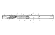
- FIG. 1 and FIG. 14 are configuration explanatory views showing the configuration of the applicator 1 according to the present invention.
- the applicator 1 has a body 2 having a substantially cylindrical shape. Moreover, the cap 3 and the inner cap 4 are provided.
- the application member 5 is usually composed of a fiber member, and is configured so that a liquid application material 6 described later can be gradually impregnated by a capillary phenomenon or the like.
- Numeral 7 indicates an absorber. As can be understood from FIG. 1 and FIG. 14, the absorber 7 is formed in a cylindrical shape without any irregular shape on the outer peripheral surface, and a through hole penetrating in the axial direction at the center in the axial direction. 8 is provided.
- the application member 5 is inserted through the through hole 8 and attached thereto.
- the absorber 7 has been made of a resin molded product whose outer periphery is configured as an uneven surface having a bellows shape. Since the cost is relatively high, the cost of the applicator itself has become expensive if different absorbers 7 having a plurality of types of forms are produced.
- the absorbent body 7 of the present invention is composed of a flexible member having an impregnation force such as a foam material having open cells inside, and the shape is changed by simply cutting the size and length. It is possible. Moreover, it is comprised so that a shape can be changed easily by compressing to a longitudinal direction or a diameter direction.
- Numeral 9 is a nose piece, which is fixed to the distal end portion of the body 2 while holding the distal end side of the coating member 5 having the core shape.
- a drawing member 10 is fitted and attached to the distal end side of the coating member 5, and is configured to draw or apply using the liquid coating material 6 impregnated with the drawing member 10.
- reference numeral 11 denotes a plug, which is inserted through and held in the body 2 at the rear end side of the application member 5, and the rear end portion is exposed to the side of the storage portion 12 formed next.
- the plug 11 holds the application member 5 by penetrating the inside of the insertion hole 16 on the rear end side of the application member 5 as described above.
- the shape of the insertion hole 16 is a different shape such as a square shape or a hexagonal shape. This adjusts the width
- the liquid coating material 6 is stored in the storage portion 12.
- symbol 13 shows the stopper for forming the said storage part 12.
- FIG. Therefore, the stopcock 13 can be attached to any location in the longitudinal direction of the body 2, so that the area of the reservoir 12 can be easily changed.
- Reference numeral 14 denotes a ball. After the liquid coating material 6 is stored in the storage section 12, the ball 14 is placed in the storage section 12, so that the impregnation of the liquid coating material 6 into the coating member 5 can be promoted. The liquid coating material 6 can be used without waste. There is also a type of applicator 1 that does not have a ball 14.
- the drawing member 10 is attached to the front end side through the nose piece 9 in the body 2, and the absorber cut to a desired length on the rear end side. 7 and the core-shaped application member 5 to which the plug 11 is attached are attached. Thereafter, the liquid coating material 6 is filled into the storage area 12 as a desired area space from the rear end opening 15 of the body 2, and the liquid coating material 6 is stored in the storage section 12 by being covered with a stopper 13. . Thereafter, the rear end of the body 2 is covered with the tail plug 17 to complete the assembly.
- the viscosity of the liquid coating material 6 varies depending on the type thereof. Therefore, in the case of the liquid coating material 6 having a small viscosity, liquid leakage occurs from the drawing member 10 attached to the tip of the coating member 5. There was a case.
- the applicator was configured by changing the length of the absorber 7 or by changing the size of the storage portion 12, but that alone ultimately The liquid leakage could not be solved.
- the applicator even if the applicator incorporates the absorbent body 7 having the same size (length) and the storage portion 12 designed to have the same size, it is adapted to the bulk viscosity of each type.
- the applicator 1 that does not leak liquid can be constituted by the one type of applicator 1. That is, the compression member 20 that compresses the absorbent body 7 accommodated in the body 2 of the applicator 1 and changes the size (length) of the absorbent body 7 is provided in the body 2.
- the absorber 7 is formed of a foam material having open cells inside as described above. And this absorber 7 has the through-hole 8 which the coating member 5 penetrates to an axial direction so that it may be understood from a figure.
- the compression member 20 is interposed on one side of the absorber 7, the absorber 7 is compressed in the longitudinal direction by the length of the interposed compression member 20. Become. That is, when the absorbent body 7 has a length of 20 mm, if the compression member 20 having a length of 4 mm is interposed, the absorbent body 7 is compressed to a length of 16 mm and contracts.
- the absorbent body 7 When the absorbent body 7 is compressed, the absorbent body 7 formed of a foam material having open cells in the inside thereof has improved adhesion with the coating member 5 inserted into the through hole 8 and penetrates into the coating member 5 side.
- the applied liquid coating material 6 is sucked up by capillary action. Therefore, the excess liquid coating material 6 is not impregnated on the side of the coating member 5 or the drawing member 10, and as a result, liquid leakage of the liquid coating material 6 can be prevented.
- FIG. 6 shows the experimental results.
- three applicators 1 having the same configuration are prepared as Sample 1, Sample 2, and Sample 3, and each has no compression member 20, the compression member 20 has a length of 4 mm, and the compression member 20.
- a swing inspection test after filling the liquid coating material 6 having a length of 5.5 mm was performed. The swing inspection is an inspection in which the applicator 1 is held and the applicator 1 is shaken several times in the vertical direction. Thus, it was inspected how many times the liquid leaked when shaken.
- the viscosity of the liquid coating material 6 was 6.0 CP (centipoise).
- the absorbent member 7 when the absorbent member 7 is compressed by providing a compression member 20 having a length of 5.5 mm, the sample 1 leaks when it is shaken 12 times, and the sample 2 leaks when it is shaken 11 times. In Sample 3, liquid leakage occurred when shaken 13 times.
- liquid coating material 6 was tested again by changing the viscosity to 5.0 CP (centipoise).
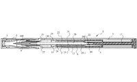
- FIG. 7 is a configuration explanatory view showing the configuration of the applicator 1 according to another embodiment of the present invention.
- the applicator 1 according to the present invention has a body 2 having a substantially cylindrical shape.
- the length of the body 2 is stipulated in the standard, and each type of applicator 1 is constituted by the body 2 having the same length even if the viscosity and material of the liquid application material 6 stored therein are different. it can. Therefore, even if a plurality of types of applicators 1 are formed, the same one can be used for the body 2 and finally the manufacturing cost can be reduced.
- the cap 3 and the inner cap 4 are attached to the tip of the body 2.
- a long coating member 5 having a core shape is held in the body 2.
- the coating member 5 is attached to the relay core 21 and the distal end of the relay core 21.
- the coating brush 100 is configured to be fitted and used for drawing.
- the relay core 21 and the application brush 100 are usually made of fiber members, and are configured so that the liquid application material 6 described later can be gradually impregnated by a capillary phenomenon or the like.
- Numeral 7 indicates an absorber.
- the absorbent body 7 is formed in a cylindrical shape that does not have any irregular shape on the outer peripheral surface, and the axial center portion thereof has an opening 200 provided on the surface to the back side in the axial direction.
- a long hole 80 is formed.
- the rear end portion 22 of the coating member 5 is fitted into the long hole 80 so that the coating member 5 and the absorber 7 can come into contact with each other, and both are connected.
- the absorbent body 7 has been made of a resin molded product whose outer periphery is configured as an accordion-shaped uneven surface.
- the mold cost of the resin molded product is high, and therefore, there are a plurality of types. If different absorbers 7 having different forms were produced, there was a problem that the cost of the applicator itself would be expensive.
- the absorbent body 7 of the present invention is composed of, for example, a flexible member having an impregnation force such as a foam material having open cells inside, and the shape and the length of the absorbent body 7 can be easily cut. It can also be changed.
- Numeral 9 is a nose piece, which is fixed to the distal end portion of the body 2 while holding the distal end side of the coating member 5 having the core shape.
- the application brush 100 is connected to and attached to the distal end side of the application member 5 so as to be fitted on the relay core 21, and the liquid application material 6 impregnated with the application brush 100 is used. And configured to draw or apply.
- the application member 5 may be configured by connecting separate parts of the relay core 21 and the application brush 100, or the application member 5 in which the relay core 21 and the application brush 100 are integrally formed. I do not care.
- symbol 23 indicates snorkel.
- the snorkel 23 is formed in a long and substantially cylindrical shape, and is configured such that the above-described relay core 21 can be inserted into a through space 25 penetrating in the axial direction inside.
- the rear end of the relay core 21 is exposed from the snorkel 23, and the rear end 22 is fitted and held in the long hole 80 of the absorber 7 as described above.
- the space between the outer peripheral surface of the snorkel 23 and the inner peripheral surface of the body 2 is configured as a storage portion 12 for the liquid coating material 6.
- the tip end side of the snorkel 23 is configured as a bulging cylindrical body 26 having a larger hole than the shape of the through space 25, and the plug 11 is fitted in the bulging cylindrical body 26.
- Reference numeral 140 can also be referred to as a so-called second absorber, which has a through-hole through which the relay core 21 passes, one end face of which is in contact with the end face of the plug 11, and the other end face is a locking protrusion of the body 2. Locked to the portion 27 and mounted in the body 2.
- the through space 25-1 on the rear end side of the snorkel 23 is not formed in a cylindrical shape that is in contact with the columnar outer peripheral surface of the relay core 21.
- a polygonal shape such as a hexagonal shape or an octagonal shape is used.
- the penetrating space 25 is formed as a shape, and the outer peripheral surface of the relay core 21 and the penetrating space 25 are in contact with each other at, for example, six points or eight points. Can be impregnated from the outer peripheral surface of the relay core 21. Further, air can be introduced from the gap, and the liquid coating material 6 can be smoothly impregnated into the relay core 21, that is, the capillary phenomenon can be smoothly performed.
- the diameter of the through space 25-2 located on the front end side from the intermediate portion of the snorkel 23 is formed larger than the diameter of the relay core 21, and thus the through space 25- located on the front end side from the intermediate portion of the snorkel 23. 2, the liquid coating material 6 can flow in, and a gap through which air can flow, that is, a clearance portion 28 can be formed.
- the absorber 7 described above is attached to the rear end side of the tail plug 17, for example, and the tail plug 17 is inserted into the body 2 from the rear opening of the body 2, and the oblong hole 80 of the absorber 7 is inserted.
- the relay core 21 is fitted to the absorbent core 7 so that the absorbent body 7 and the relay core 21 are in contact with each other, and the absorbent body 7 is disposed in the storage portion 12 in which the liquid coating material 6 is stored. Therefore, the absorbent body 7 is constantly impregnated with the liquid coating material 6. Since the absorbent body 7 is always in contact with the relay core 21, the impregnated liquid coating material 6 can be supplied to the relay core 21 side by capillary action.
- the amount of the liquid coating material 6 in the storage portion 12 is reduced, the state in which the applicator 1 is used in parallel is lengthened, and the liquid coating material 6 in the storage portion 12 is exposed to the storage member 12. Even when it does not reach the relay core 21, the liquid coating material 6 can be supplied from the absorbent body 7 that has been impregnated with the liquid coating material 6 in advance, so that the application brush 100 does not run out of liquid. In that sense, it can be said that the absorbent body 7 serves as a reserve tank for the liquid coating material 6.
- the assembly of the applicator according to the present invention will be described.
- the second absorbent body 140 is attached to the distal end side, and the snorkel 23 with the plug 11 fitted next to the second absorbent body 140 is fitted.
- the relay core 21 is inserted from the rear of the body 2.
- the tail plug 17 to which the absorber 7 is attached is inserted from the rear of the body 2 so that the relay core 21 is mounted at a predetermined position, and the relay core 21 and the absorber 7 are brought into contact with each other and connected to each other. Wear.
- the reservoir 12 needs to be filled with the liquid coating material 6 in advance.
- the application brush 100 with the nosepiece 9 attached is connected from the front end side of the body 2 to the front end side of the relay core 21. And the inner cap 4 and the cap 3 are attached to the front end side of the body 2, and the assembly of the applicator 1 is thereby completed.
- FIGS. 8 and 9 show another embodiment of the present invention, which is an example of a configuration in which the length and size of the absorber 7 are changed.
- the size and length of the absorbent body 7 can be freely changed. Therefore, even if there is a difference in the viscosity or material of the liquid coating material 6, the absorbent body 7 can be used without any problem. It is possible to fulfill the function of the spare tank.
- the gap serves as an air inflow path, and the relay core 21 can be smoothly impregnated with the liquid coating material.
- the presence of the second absorber 140 can adjust the amount of impregnation of the liquid coating material 6 into the relay core 21, thereby preventing liquid leakage and liquid breakage.
- FIG. 10 is a configuration explanatory view showing the configuration of the double-use applicator 101 according to the present invention.
- the applicator 101 according to the present invention has a body 2 having a substantially cylindrical shape. And the structure which has the cap 171 and the inner cap 181 at the both ends of the said body 2, and can be used double is employ
- the core-shaped application member 5 is held and attached from a pair of both sides.
- the pair of applicator members 5 is usually composed of a fiber member so that a liquid applicator material 6 described later can be gradually impregnated by a capillary phenomenon or the like.
- the application member 5 is attached so that two can be used from both ends in the longitudinal direction of the body 2.
- reference numeral 7 denotes an absorbent body. As can be understood from FIG. 10, two absorbent bodies 7 are attached in the longitudinal direction of the application member 5.
- the coating member 5 is inserted through the through hole 8 and attached thereto.
- the absorbent body 7 is made of a resin molded product whose outer periphery is configured as an accordion-like uneven surface.
- the mold cost of the resin molded product is high, and therefore, different forms of multiple types are formed.
- the absorber 7 was produced, the cost of the applicator itself was expensive.
- the absorbent body 7 of the present invention is composed of a flexible member having an impregnation force such as a foam material having open cells inside, and the shape is changed by simply cutting the size and length. It is possible.
- Numeral 9 is a nosepiece, which holds the tip side of the coating member 5 having the core shape and is fixed to the tip portion of the body 2.
- a drawing member 10 is fitted and attached to the distal end side of the coating member 5, and is configured to draw or apply using the liquid coating material 6 impregnated with the drawing member 10.
- Numeral 11 is a plug, which penetrates and holds the rear end side of the application member 5 in the body 2 and exposes the rear end portion to the storage portion 12 formed next.
- the plug 11 holds the coating member 5 by penetrating the inside of the plug through-hole 161 on the rear end side of the coating member 5.
- the shape of the through-hole 161 is rectangular or hexagonal. Different shapes. This adjusts the width
- the liquid coating material 6 is stored in the storage portion 12.
- a projecting piece 211 projecting in the longitudinal direction of the body 2 is provided on the storage part 12 side of the plug 11, and the rear end part of the application member 5 is formed in the projecting piece 211. .
- the ball 14 does not directly collide with the rear end portion of the application member 5, and the rear end portion of the application member 5 can be protected.
- the plug 11 is also used at an intermediate position of the application member 5, and the liquid application material 6 is prevented from leaking or excessively infiltrating by the plug 11 provided at the intermediate position.
- Reference numeral 14 denotes a ball. After the liquid coating material 6 is stored in the storage section 12, the ball 14 is placed in the storage section 12, so that the impregnation of the liquid coating material 6 into the coating member 5 can be promoted. The liquid coating material 6 can be used without waste. There is also a double-use applicator 1 that does not have a ball 14.
- a partition wall 30 that can be punched out is provided in advance in the body 2 that constitutes the applicator 1 of the present invention.
- the partition wall 30 is provided with a notch 201 at a connection portion between the partition wall 30 and the inner peripheral surface of the body 2, for example, by pushing the partition wall 30 along the longitudinal direction of the body 2.
- the partition wall 30 can be easily separated from the body 2.
- the applicator 1 shown in FIG. 12 is a type in which an applicator for drawing using a liquid applicator 6 is attached on one side and a powder member 40 for face is attached on the other side.
- a double-use applicator 1 there is no need to punch out the partition wall 30 and supply the liquid applicator 6 to the powder member 40 side. Therefore, the partition wall 30 is used without being punched out.
- an applicator for drawing using the liquid applicator 6 is attached on one side, and a pencil member 130 for the face is attached on the other side.
- a pencil member 130 for the face is attached on the other side.
- the applicator 1 is formed on both sides of the body 2, and both require the use of the liquid coating material 6. Therefore, in the case of such double use, it is necessary to punch the partition wall 30 for use. That is, if the partition wall 30 is pierced, the liquid applicator material 6 of both applicators 101 can be covered by one reservoir 12.
- the applicator 1 that can be used for various uses can be provided.
- a drawing member 10 is attached to the front end of the body 2 via a nose piece 9 and is cut to a desired length from a substantially intermediate position toward the rear end side. 7 and the plug 11 are attached, and the core-shaped application member 5 is attached.
- the partition wall 30 is punched and removed. Thereafter, the liquid coating material 6 is filled into the storage portion 12 as a desired region space from the rear end opening 15 of the body 2.
- another application member 5 is inserted from the rear end side of the body 2. That is, the drawing member 10 is attached to the front end via the nosepiece 9, and the core 7 is attached to the absorber 7 and the plug 11 cut to a desired length from the substantially intermediate position toward the rear end side. The application member 5 is inserted and attached from the other side of the body 2.
- a drawing member 10 is attached to the tip of one side via a nose piece 9, and the absorber 7 and the plug cut to a desired length from the substantially intermediate position toward the rear end.
- a core-shaped application member 5 to which 11 is attached is attached.
- the partition wall 30 is left without being punched. That is, the liquid coating material 6 is not used on both sides of the body 2.
- the liquid coating material 6 is filled into the storage portion 12 as a desired area space from the front end opening 191 side of the body 2, and then the coating member 5 is attached as described above.
- the partition wall 30 is used without being punched out.
- the face powder member 40 and the face pencil member 130 are attached and used on the other side of the body 2, but the present invention is not limited thereto. If the liquid coating material 6 is not used, it can be attached to the other side to form a double use applicator. In such a use, the body 2 is used while leaving the partition wall 30 as it is.
Landscapes
- Coating Apparatus (AREA)
- Containers And Packaging Bodies Having A Special Means To Remove Contents (AREA)
Abstract
Description
本発明は、例えばアイライナーやアイブローのような化粧用具、あるいは頭髪や眉毛などの部分白髪染め具など内部に貯留した液状塗布材を塗布部に浸潤させ、これを先端塗布部より塗布あるいは描画して使用する塗布具に関するものである。
In the present invention, for example, a liquid application material stored inside, for example, a cosmetic device such as an eyeliner or eyebrow, or a partial gray hair dyeing device such as head hair or eyebrows is infiltrated into the application part, and this is applied or drawn from the tip application part The present invention relates to an applicator used.
従来より、アイライナーなど内部に液状塗布材を貯留し、この液状塗布材を繊維部材などからなる芯材により構成された塗布部材に吸収、浸潤させ、該塗布部材の先端塗布部によって塗布あるいは描画する塗布具が一般に知られている。 Conventionally, a liquid coating material is stored inside an eyeliner and the like, and this liquid coating material is absorbed and infiltrated into a coating member composed of a core material made of a fiber member or the like, and is applied or drawn by a tip coating portion of the coating member. An applicator to do is generally known.
これら塗布具については、内部に貯留されている液状塗布材のバルク出量調整をするため、通常、前記芯材を覆う吸収体が設けられており、この吸収体により、芯材に送出される液状塗布材の出量を調整するものとしていた。 About these applicators, in order to adjust the amount of liquid coating material stored inside, an absorbent body that covers the core material is usually provided, and the absorbent material is delivered to the core material. The amount of liquid coating material was adjusted.
従来は、図5に示す様に、この吸収体7は一般的に外周面を蛇腹状の凹凸面に形成した樹脂成形品によって作製されており、その設計には多くの調整が必要で、また高額な金型費用が必要とされていた。
Conventionally, as shown in FIG. 5, the
また、内部に液状塗布材6を貯留する貯留部12の領域も確定していて、この領域を変更できる構成にはなっていなかった。
Further, the area of the
ところで、前記液状塗布材6は、使用の態様によって、その粘性や材質が多数異なっており、また前記貯留部12に貯留させる液状塗布材6の貯留量も様々異なるものである。
By the way, the
よって、上記のように、複数種類存在する液状塗布材6に対応させ、しかもその貯留量の異なる場合も含めて同じ形状で同じ大きさの構造をなす塗布具や内部の吸収体7を使用することは困難なこととされていた。
Therefore, as described above, the applicator and the internal
すなわち、長さなどを変更した樹脂成形品からなる吸収体7を別々に作製することは、高額な金型費用を必要とし、また、前記貯留量を変更するには塗布具の大きさそのものを変更しなければならないとの課題があるからである。
That is, separately producing the
ところで、前記バルクの粘度は、バルク液の種類によって異なっており、粘度の異なったバルク液にあわせて、液漏れが起こらないようそれぞれ塗布具の形状を変更することはきわめてコスト高になり、到底容認されるものではなかった。 By the way, the viscosity of the bulk varies depending on the type of the bulk liquid, and it is extremely expensive to change the shape of the applicator according to the bulk liquid having different viscosities so as not to cause liquid leakage. It was not acceptable.
そこで前記バルクの粘度が異なる場合であっても、同じ規格の塗布具を用いることが出来、しかもそれぞれ液漏れが起こらないように構成された塗布具が要請されていた。 Therefore, even when the bulk has different viscosities, there has been a demand for an applicator that can use the same standard applicator and that does not leak.
さらに、一般的な塗布具は、塗布具内に貯留されたバルク液が少なくなると、芯材に送出される液状塗布材の出量が保持できなくなる傾向にあった。なぜなら塗布具の使用状態はそれを平行にして使用するか或いは少し後端側を下げて使用することが多く、その様な使用状態であると、芯材への貯留部からのバルク液の含浸がうまく調整出来ないからである。
Furthermore, when the bulk liquid stored in the applicator decreases, the general applicator tends to be unable to maintain the amount of liquid applicator delivered to the core material. Because the usage state of the applicator is often used in parallel or slightly lowering the rear end side, in such a usage state, impregnation of the bulk liquid from the reservoir to the core material This is because cannot be adjusted well.
かくして、本発明による塗布具は、前記従来の課題を解決するために創案されたものであって、内部に貯留させる液状塗布材、すなわちバルク液につき、その粘性や材質の異なるものが複数種類存在し、また前記貯留部に貯留させる液状塗布材の貯留量も様々異なるものであったとしても、この複数種類存在するバルク液に対応でき、しかもそのバルク液の粘度が異なる場合であっても、例えば大きさや形状など同じ規格の塗布具を用いることが出来、それぞれ液漏れが起こらないように構成された塗布具を提供することを目的とし、また塗布具を平行にして使用するか或いは少し後端側を下げて使用した状態が長くなったとしても、芯材への貯留部からのバルク液の含浸が調整出来て、たとえバルク液の量が少なくなってきたとしても最後まで液切れしない塗布具を提供することを目的とし、さらには、ダブル使用できるタイプの塗布具で、双方側の使用につき液状塗布材を使用した塗布具として使用する場合も、一方側が塗布具で他方側はパウダーとしての使用のものでも、さらには他方側には白髪染めとしての塗布具の使用した場合にも、同一規格のボディを使用して作製でき、作製の手間とコストを安価に出来る塗布具を提供することを目的とするものである。
Thus, the applicator according to the present invention has been devised to solve the above-described conventional problems, and there are a plurality of types of liquid coating materials to be stored inside, that is, bulk liquids having different viscosities and materials. And even if the storage amount of the liquid coating material to be stored in the storage part is variously different, even if it can correspond to this multiple types of bulk liquid, and the viscosity of the bulk liquid is different, For example, it is possible to use an applicator of the same standard such as size and shape, and the purpose is to provide an applicator configured so that no liquid leakage occurs, and the applicator is used in parallel or a little later Even if the end side is lowered and used for a long time, the impregnation of the bulk liquid from the reservoir to the core material can be adjusted, even if the amount of bulk liquid decreases In addition, it is a type of applicator that can be used double, and even when it is used as an applicator that uses a liquid applicator for both sides, one side is an applicator. Even if the other side is used as a powder, and the other side is used as an application tool for white hair dyeing, it can be manufactured using the same standard body, which can reduce the manufacturing effort and cost. The purpose is to provide ingredients.
本発明による塗布具は、
略円筒状をなすボディと、該ボディ内に収納される芯状をなす塗布部材と、塗布部材に含浸する液状塗布材を貯留する貯留部と、前記塗布部材への液状塗布材の含浸量を調整する液状塗布材吸収体と、
前記ボディ内において前記塗布部材の後端側につき、穿設された貫挿孔を貫挿させて保持すると共に、該後端側を、貯留部側へ露出させてなり、前記貫挿孔の形状は、前記液状塗布材の粘性や材質に対応して、前記貫挿孔と貫挿する塗布部材との間の隙間の幅が調整でき、液状塗布材吸収体側に浸潤する液状塗布材の量を調整できるプラグと、を備え、
前記貯留部は、前記止栓の取り付け位置の変更により液状塗布材の貯留領域が増減可能に構成され、
前記液状塗布材吸収体は、前記塗布部材につき、前記プラグの取り付け位置より先端側に取り付けられ、前記液状塗布材の含浸量を増減可能にすべく、切断によって長さや大きさを変更可能に構成された、
ことを特徴とし、
または、
略筒状をなすボディと、該ボディ内に収納される塗布部材と、塗布部材に含浸する液状塗布材を貯留する貯留部と、前記塗布部材への液状塗布材の含浸量を調整する液状塗布材吸収体と、前記ボディ内に設けられた液状塗布材吸収体をボディ内で圧縮する圧縮部材と、を備え、
前記圧縮部材は、前記液状塗布材吸収体のボディ内での圧縮程度を変更可能とされて前記塗布部材へ含浸する液状塗布材の含浸量を調整できる構造とされた、
ことを特徴とし、
または、
前記液状塗布材吸収体は、内部に連続気泡構造体を有するフォーム材で構成された、
ことを特徴とし、
または、
前記貯留部内には、撹拌用のボールが設けられた、
ことを特徴とし、
または、
略円筒状をなすボディと、該ボディ内に収納され、ボディの長手方向一端から描画可能に構成された先端部を有する芯状をなす塗布部材と、前記ボディ内に設けられ、前記塗布部材に含浸する液状塗布材を貯留する貯留部と、前記ボディ内に収納された前記塗布部材後端側につき、貯留部側へ露出させて前記液状塗布材を塗布部材に含浸可能な構成とし、かつ前記塗布部材後端部を保持すると共に、液状塗布材を含浸出来るよう前記貯留部内に取り付けられた吸収体に接触状態としてなり、
前記吸収体は、前記液状塗布材の粘性や材質に応じて前記含浸量が調節できるよう長さや大きさが変更できる、
ことを特徴とし、
または、
前記芯状をなす塗布部材は、繊維部材で構成され、前記液状塗布材が毛細管現象により含浸できるよう構成された、
ことを特徴とし、
または、
前記塗布部材は、長尺の中継芯と該中継芯の先端に接続された塗布用ブラシとを有して構成された、
ことを特徴とし、
または、
略円筒状をなすボディと、該ボディ内に収納され、ボディの長手方向一端側から描画可能に構成された芯状をなす塗布部材と、前記塗布部材の後端側に設けられ、前記塗布部材に含浸する液状塗布材を貯留する貯留部と、前記塗布部材への液状塗布材の含浸量を調整する液状塗布材吸収体と、を有し、
前記貯留部を形成する後端側仕切り壁と、該仕切り壁から前記ボディの長手方向他端側に向かって設けられた空間には、前記ボディの長手方向一端側に取り付けられた芯状の塗布部材と同規格の塗布部材が取り付け可能とされ、
前記ボディの両側に塗布部材が取り付けられたとき、前記貯留部を形成する前記仕切り壁が打ち抜かれ、前記貯留部の液状塗布材を前記ボディの両側に塗布部材で兼用できる、
ことを特徴とし、
または、
前記ボディの長手方向他端側の空間には、塗布部材に替えて、前記塗布部材以外の化粧用部材が取り付け可能とされ、その場合には、前記仕切り壁は打ち抜かないで残される、
ことを特徴とするものである。
The applicator according to the present invention comprises:
A substantially cylindrical body, a core-shaped application member housed in the body, a reservoir for storing a liquid application material impregnated in the application member, and an amount of liquid application material impregnated in the application member; A liquid coating material absorber to be adjusted;
In the body, a penetrating hole formed on the rear end side of the coating member is inserted and held, and the rear end side is exposed to the storage portion side, and the shape of the through hole is formed. Corresponds to the viscosity and material of the liquid coating material, the width of the gap between the insertion hole and the coating member to be inserted can be adjusted, and the amount of liquid coating material infiltrating the liquid coating material absorber side can be adjusted. With an adjustable plug,
The storage part is configured such that the storage area of the liquid coating material can be increased or decreased by changing the attachment position of the stopcock,
The liquid coating material absorber is attached to the tip side of the coating member from the mounting position of the plug, and the length and size can be changed by cutting so that the amount of impregnation of the liquid coating material can be increased or decreased. Was
It is characterized by
Or
A body having a substantially cylindrical shape, an application member housed in the body, a reservoir for storing a liquid application material impregnated in the application member, and a liquid application for adjusting an impregnation amount of the liquid application material into the application member A material absorber, and a compression member that compresses the liquid coating material absorber provided in the body within the body,
The compression member has a structure in which the degree of compression in the body of the liquid coating material absorber can be changed and the amount of liquid coating material impregnated into the coating member can be adjusted.
It is characterized by
Or
The liquid coating material absorber is composed of a foam material having an open cell structure inside,
It is characterized by
Or
In the storage part, a stirring ball was provided,
It is characterized by
Or
A body having a substantially cylindrical shape, a coating member that is housed in the body and has a core shape having a tip portion that can be drawn from one end in the longitudinal direction of the body, and provided in the body. A storage section for storing the liquid coating material to be impregnated, and a rear end side of the coating member housed in the body, the liquid coating material being exposed to the storage section side so that the coating member can be impregnated, and While holding the rear end portion of the application member, it is in contact with the absorber attached in the reservoir so that the liquid application material can be impregnated,
The absorber can be changed in length and size so that the amount of impregnation can be adjusted according to the viscosity and material of the liquid coating material.
It is characterized by
Or
The core-shaped application member is composed of a fiber member, and the liquid application material is configured to be impregnated by capillary action.
It is characterized by
Or
The coating member is configured to have a long relay core and a brush for application connected to the tip of the relay core.
It is characterized by
Or
A body having a substantially cylindrical shape, a core-shaped coating member housed in the body and configured to be drawn from one longitudinal end of the body, and the coating member provided on the rear end side of the coating member; A reservoir for storing the liquid coating material impregnated in the liquid, and a liquid coating material absorber for adjusting the amount of liquid coating material impregnated into the coating member,
In the space provided from the partition wall toward the other end side in the longitudinal direction of the body, a core-like coating attached to one end side in the longitudinal direction of the body is formed. The application member of the same standard as the member can be attached,
When the application member is attached to both sides of the body, the partition wall forming the storage part is punched out, and the liquid application material of the storage part can be shared with the application member on both sides of the body.
It is characterized by
Or
In the space on the other end side in the longitudinal direction of the body, a cosmetic member other than the application member can be attached instead of the application member, and in that case, the partition wall is left without being punched.
It is characterized by this.
本発明による塗布具であれば、内部に貯留させる液状塗布材につき、その粘性や材質の異なるものが複数種類存在し、また前記貯留部に貯留させる液状塗布材の貯留量も様々異なるものであったとしても、この複数種類存在する液状塗布材に対応でき、しかもそのバルク液の粘度が異なる場合であっても、例えば大きさや形状につき同じ規格の塗布具を用いることが出来、それぞれ液漏れが起こらないように構成でき、さらには塗布具を平行にして使用するか或いは少し後端側を下げて使用した状態が長くなったとしても、芯材への貯留部からのバルク液の含浸が調整出来て、たとえバルク液の量が少なくなってきたとしても最後まで液切れしない塗布具を提供でき、また、ダブル使用タイプの塗布具であって、双方の使用につき液状塗布材を使用した塗布具として使用する場合も、一方側が塗布具で他方側はパウダーとしての使用のものでも、さらには他方側には白髪染めとしての塗布具の使用した場合にも、同一規格のボディを使用して作製でき、ダブル使用対応の塗布具作製の手間とコストを安価に出来るとの優れた効果を奏する。
In the case of the applicator according to the present invention, there are a plurality of types of liquid application materials that are stored in the interior, and the viscosity and material of the liquid application materials are different, and the storage amount of the liquid application material stored in the storage section is also different. Even if it is possible to deal with this plurality of types of liquid coating materials, and even when the bulk liquid has different viscosities, for example, the same standard applicator can be used for each size and shape. Can be configured so that it does not occur, and even if the applicator is used in parallel or the back end side is lowered slightly, the impregnation of the bulk liquid from the reservoir to the core material is adjusted It is possible to provide an applicator that does not run out until the end even if the amount of bulk liquid is reduced, and it is a double use type applicator that is a liquid application material for both uses Even when used as a used applicator, the same standard body is used even when one side is used as an applicator and the other side is used as a powder, and the other side is used as a white hair dyeing applicator. And has the excellent effect of reducing the labor and cost of preparing an applicator for double use.
以下、本発明を図に示す実施例に基づいて説明する。 Hereinafter, the present invention will be described based on embodiments shown in the drawings.
図1、図14は、本発明による塗布具1の構成を示す構成説明図である。 FIG. 1 and FIG. 14 are configuration explanatory views showing the configuration of the applicator 1 according to the present invention.
本発明による塗布具1は、略円筒状をなすボディ2を有している。また、キャップ3及びインナーキャップ4を有している。
The applicator 1 according to the present invention has a
ボディ2内には芯状をなす塗布部材5が保持されている。当該塗布部材5は通常繊維部材で構成され、後述する液状塗布材6が毛細管現象などによって徐々に含浸できるように構成されている。
In the
符号7は、吸収体を示す。図1、図14から理解出来る様に、当該吸収体7は、外周面に何らの凹凸形状も施さない円柱状に構成され、その軸方向中心部には、軸方向に向かって貫通する貫通孔8が設けられている。
そして、この貫通孔8に前記塗布部材5が貫挿して取り付けられている。従来この吸収体7は、図4、図5に示すように、外周が蛇腹状の凹凸面として構成された樹脂成形品で作製されていたが、前記したように、前記樹脂成形品の金型費用が比較的高額であり、そのため複数種類の形態をなす異なった吸収体7を作製すると塗布具自体のコストが高価となってしまっていた。
The
しかして、本発明の吸収体7は、例えば、内部に連続気泡を有するフォーム材などの含浸力を有する柔軟部材で構成されており、その大きさや長さを簡単に切断することにより形状が変更できるものとなっている。また、長手方向や直径方向へ圧縮することにより形状を容易に変更できるように構成してある。
Thus, the
符号9はノーズピースであり、前記芯状をなす塗布部材5の先端側を保持して、ボディ2の先端部に固着している。尚、前記塗布部材5の先端側には描画部材10が被嵌して取り付けられており、該描画部材10により含浸した液状塗布材6を使って、描画あるいは塗布するように構成されている。
次に、符号11は、プラグであり、ボディ2内において塗布部材5の後端側を貫挿させて保持すると共に、その後端部を隣に形成された貯留部12側へ露出させている。尚、図3から理解されるように、プラグ11は前述のように、塗布部材5の後端側につき、貫挿孔16内を貫挿させて塗布部材5を保持しているが、この貫挿孔16の形状は四角状あるいは六角形状など異なった形状にしてある。これは液状塗布材6の粘性や材質に対応して貫挿孔16とこれを貫挿する塗布部材5との間の隙間の幅を調整し、吸収体7側に浸潤する液状塗布材6の量を調整しようとしたものである。ここで、前記貯留部12には液状塗布材6が貯留されるものとなる。
Next,
また、符号13は、前記貯留部12を形成するための止栓を示す。しかして、該止栓13はボディ2の長手方向においていずれの箇所にも取り付け可能とされており、もって、貯留部12の領域は簡単に変更できるものとなっている。
Moreover, the code |
符号14はボールであり、貯留部12に液状塗布材6を貯留した後、当該ボール14を該貯留部12に入れることにより、液状塗布材6の塗布部材5への含浸を促進でき、最後まで無駄なく液状塗布材6を使用できるものとなっている。尚、ボール14を有しないタイプの塗布具1も存在する。
次に、塗布具1の組立につき説明すると、まず、ボディ2内に先端側にノーズピース9を介して描画部材10が取り付けられ、後端側には、所望の長さにカットされた吸収体7とプラグ11が取り付けられた芯状の塗布部材5が取り付けられる。その後、ボディ2の後端開口15から液状塗布材6を、所望の領域空間とした貯留部12内に充填し、止栓13により蓋をして液状塗布材6を貯留部12内に貯留する。その後、尾栓17でボディ2の後端に蓋をして組立は終了する。
Next, the assembly of the applicator 1 will be described. First, the drawing
ところで、前記液状塗布材6は、その種類によって粘度がまちまちであり、そのため粘度の小さな液状塗布材6の場合には、前記塗布部材5の先端に取り付けられた描画部材10側より液漏れが生じてしまうことがあった。
By the way, the viscosity of the
しかしながら、従来ではこの液漏れを防止するために、前記吸収体7の長さを異ならせたり、前記貯留部12の大きさを異ならせて塗布具を構成していたが、それだけでは最終的に前記液漏れを解消することが出来なかった。
However, in the past, in order to prevent this liquid leakage, the applicator was configured by changing the length of the
そこで、図1に示す発明では、同じ大きさ(長さ)の吸収体7や同じ大きさに設計された貯留部12を組み込んだ塗布具であっても、それぞれの種類のバルク粘度にあわせて液漏れの生じない塗布具1が前記一種類の塗布具1で構成できる発明としたのである。すなわち、塗布具1のボディ2内に収納された前記吸収体7を圧縮し、その吸収体7の大きさ(長さ)を変更する圧縮部材20をボディ2内に設けたのである。
Therefore, in the invention shown in FIG. 1, even if the applicator incorporates the
ここで、吸収体7は前述のように、内部に連続気泡を有するフォーム材で形成してある。そして、この吸収体7は、図から理解される様に、軸方向に塗布部材5が貫通する貫通孔8を有している。
Here, the
そして、図1に示すように、吸収体7の一方側に圧縮部材20を介在させれば、介在させた圧縮部材20の長さの分だけ、吸収体7は長手方向に圧縮されることになる。すなわち、吸収体7が20mmの長さであるとき、4mmの長さの圧縮部材20を介在させれば、吸収体7は16mmの長さに圧縮され、縮むことになる。
As shown in FIG. 1, if the
吸収体7が圧縮されると、内部に連続気泡を有するフォーム材で形成された吸収体7は、貫通孔8に貫挿された塗布部材5との密着性が高まり、塗布部材5側に浸透した液状塗布材6を毛細管現象によって吸い上げるものとなる。よって塗布部材5や描画部材10側には余分な液状塗布材6が含浸せず、その結果液状塗布材6の液漏れが防止出来るものとなる。
When the
図6に、その実験結果を示す。図6では同様の構成からなる塗布具1をサンプル1、サンプル2、サンプル3として3個作成し、それぞれにつき、圧縮部材20のないもの、圧縮部材20の長さが4mmのもの、圧縮部材20の長さが5.5mmのものの液状塗布材6充填後の振り検査試験を行った。振り検査とは、塗布具1を持ち、持った塗布具1を上下方向に数回振る検査である。これにより何回振ったときに液漏れが生じるのかを検査した。
Fig. 6 shows the experimental results. In FIG. 6, three applicators 1 having the same configuration are prepared as Sample 1,
ここで、液状塗布材6の粘度は6.0CP(センチポアズ)とした。
Here, the viscosity of the
すると、図6に示す様に、圧縮部材20のないものについては、サンプル1、サンプル2では6回振ったときに液漏れが生じ、サンプル3では5回振ったときに液漏れが生じた。また、4mmの圧縮部材20をボディ2内に設けて吸収体7を圧縮したときには、サンプル1では8回振ったときに液漏れが生じ、サンプル2では7回振ったときに液漏れが生じ、サンプル3では9回振ったときに液漏れが生じた。
Then, as shown in FIG. 6, in the samples without the
さらに、5.5mmの長さの圧縮部材20を設けて吸収体7を圧縮したときには、サンプル1では12回振ったときに液漏れが生じ、サンプル2では11回振ったときに液漏れが生じ、サンプル3では13回振ったときに液漏れが生じた。
Furthermore, when the
次に、液状塗布材6の粘度を5.0CP(センチポアズ)に替えて再度試験をしてみた。
Next, the
すると、圧縮部材20のないものについては、サンプル1、サンプル2、サンプル3では4回振ったときに液漏れが生じた。また、4mmの長さの圧縮部材20を設けて吸収体7を圧縮したときには、サンプル1では6回振ったときに液漏れが生じ、サンプル2では7回振ったときに液漏れが生じ、サンプル3では6回振ったときに液漏れが生じた。
Then, in the case where the
さらに、5.5mmの長さの圧縮部材20を設けて吸収体7を圧縮したときには、サンプル1、サンプル2では9回振ったときに液漏れが生じ、サンプル3では10回振ったときに液漏れが生じた。
Furthermore, when the
この様に、圧縮部材20を用い、吸収体7を長手方向に圧縮して、塗布部材5との密着性を高めると、塗布部材5側に余分な液状塗布材6が浸透せず、吸収体7が余分な液状塗布材6を吸収してくれる。
Thus, when the
よって、その結果、本発明の塗布具1では、液漏れが生じないことが判明した。 Therefore, as a result, it was found that no liquid leakage occurred in the applicator 1 of the present invention.
次に、本発明の他の実施例について説明する。 Next, another embodiment of the present invention will be described.
図7は、本発明の他の実施例による塗布具1の構成を示す構成説明図である。本発明による塗布具1は、略円筒状をなすボディ2を有している。このボディ2の長さは一応規格で定められてあり、内部に貯留されている液状塗布材6の粘性や材質が異なっていても、同じ長さのボディ2で各種類の塗布具1を構成できる。そのため複数種類の塗布具1を形成してもそのボディ2につき同じものを使用できて最終的に製造コストを安価に出来る。
FIG. 7 is a configuration explanatory view showing the configuration of the applicator 1 according to another embodiment of the present invention. The applicator 1 according to the present invention has a
そして、当該ボディ2の先端には、キャップ3及びインナーキャップ4が装着される。
The
ここで、ボディ2内には、芯状をなす長尺の塗布部材5が保持されており、図から理解されるように、当該塗布部材5は、中継芯21と該中継芯21の先端に被嵌され、描画に使用される塗布用ブラシ100とを有して構成される。
Here, a
しかして、中継芯21および塗布用ブラシ100は、通常繊維部材で構成され、後述する液状塗布材6が毛細管現象などによって徐々に含浸できるように構成されている。
However, the
符号7は、吸収体を示す。図から理解出来る様に、当該吸収体7は、外周面に何らの凹凸形状も施さない円柱状に構成され、その軸方向中心部には、表面に設けられた開口200から軸方向奥側に向かって設けられた長孔80が形成されている。
そして、この長孔80に前記塗布部材5の後端部22が嵌まり込んで、塗布部材5と吸収体7とが接触出来るように構成され、両者が接続された状態となっている。
Then, the
従来この吸収体7は、外周が蛇腹状の凹凸面として構成された樹脂成形品で作製されていたが、前記したように、前記樹脂成形品の金型費用が高額であり、そのため複数種類の形態をなす異なった吸収体7を作製すると塗布具自体のコストが高価となってしまうとの課題があった。
Conventionally, the
しかして、本発明の吸収体7は、例えば、内部に連続気泡を有するフォーム材などの含浸力を有する柔軟部材で構成されており、その大きさや長さを簡単に切断することにより形状が容易に変更することもできる。
Thus, the
符号9はノーズピースであり、前記芯状をなす塗布部材5の先端側を保持して、ボディ2の先端部に固着している。尚、前記塗布部材5の先端側には前述したように塗布ブラシ100が中継芯21に被嵌した状態で接続されて取り付けられており、該塗布用ブラシ100により含浸した液状塗布材6を使って、描画あるいは塗布するように構成されている。このように塗布部材5を中継芯21と塗布用ブラシ100との別体部品を連結して構成しても構わないし、中継芯21と塗布用ブラシ100とを一体的に形成した塗布部材5でも構わない。
次に符号23はシュノーケルを示す。該シュノーケル23は、長尺の略筒状に形成されており、内部の軸方向に貫通する貫通空間25に前述した中継芯21が挿通出来るよう構成されている。
Next,
そして、図から理解されるように、中継芯21の後端はシュノーケル23より露出し、その後端部22が、前述したように吸収体7の長孔80に嵌り込んで保持されている。
As can be understood from the drawing, the rear end of the
また、シュノーケル23の外周面とボディ2の内周面との間の空間は、液状塗布材6の貯留部12として構成されている。
Further, the space between the outer peripheral surface of the
ここで、シュノーケル23の先端側は、前記貫通空間25の形より大きな孔を有した膨出筒体26として構成され、この膨出筒体26内にはプラグ11が嵌り込んでいる。
Here, the tip end side of the
尚、符号140はいわゆる第2吸収体とも称することが出来、中継芯21が貫通する貫通孔を有すると共に、その一方側端面はプラグ11の端面に接し、他方側端面はボディ2の係止突部27に係止してボディ2内に装着されている。
ところで、前記シュノーケル23の後端側における貫通空間25-1は、中継芯21の円柱状外周面にすべて接する円筒状には構成されておらず、例えば、6角形状或いは8角形状などの多角形状をなす貫通空間25として構成され、中継芯21の外周面と前記貫通空間25とは例えば6点或いは8点で接するが、他の外周面位置では隙間が生じ、その隙間から液状塗布材6が中継芯21の外周面から含浸できるよう構成されている。また、該隙間から空気が導入できるようになっていて、液状塗布材6が中継芯21へスムーズに含浸出来るよう、即ち毛細管現象がスムーズに行えるよう構成されている。
By the way, the through space 25-1 on the rear end side of the
すなわち、シュノーケル23の中間部から先端側に位置する貫通空間25-2の径は、中継芯21の径より大きく形成されており、よってシュノーケル23の中間部から先端側に位置する貫通空間25-2には前記液状塗布材6が流入でき、かつ空気が流入できる隙間、すなわちクリアランス部28として構成できるのである。
That is, the diameter of the through space 25-2 located on the front end side from the intermediate portion of the
ところで、前述した吸収体7は、例えば尾栓17の後端側に取り付けられており、当該尾栓17はボディ2の後方開口からボディ2内に差し込まれて、前記吸収体7の長孔80に中継芯21が嵌り込み、吸収体7と中継芯21とが接触して接続するようになっており、また吸収体7は前記液状塗布材6が貯留される貯留部12内に配置されることとなるので、該吸収体7には絶えず液状塗布材6が含浸される状態となる。そして、この吸収体7は常時中継芯21に接触しているから、含浸した液状塗布材6を毛細管現象によって中継芯21側へ供給出来るようになっているのである。したがって、貯留部12内の液状塗布材6の量が少なくなり、塗布具1を平行にして使用するような状態が長くなって、貯留部12の液状塗布材6が前記貯留部材12に露出してある中継芯21に届かなくなった場合でも、あらかじめ液状塗布材6を含浸した吸収体7から液状塗布材6が供給出来、もって塗布用ブラシ100において液切れ状態を引き起こすことがないのである。その意味からすると前記吸収体7は液状塗布材6の予備タンクの役目を果たしていると言える。
By the way, the
ここで、本発明による塗布具の組み立てにつき説明すると、例えば、先端側に第2吸収体140が取り付けられ、この第2吸収体140の隣にプラグ11が嵌着されたシュノーケル23が被嵌された中継芯21がボディ2の後方から差し込まれる。次いで、吸収体7を取り付けた尾栓17をボディ2の後方から差し込んで、前記中継芯21を所定の位置に装着させると共に、中継芯21と吸収体7とを接触、接続させて尾栓17を装着する。尚、前記尾栓17を装着する前に、あらかじめ貯留部12には液状塗布材6を充填しておく必要がある。
Here, the assembly of the applicator according to the present invention will be described. For example, the second
さらに、ボディ2の先端側から、中継芯21の先端側にノーズピース9が装着された塗布用ブラシ100を連結させる。そして、ボディ2の先端側にインナーキャップ4およびキャップ3を取り付け、これにより塗布具1の組み立てが完了する。
Further, the
図8、図9は本発明の他の実施例を示すものであり、吸収体7の長さ、大きさを変更した構成の例である。このように吸収体7の大きさや長さは自在に変更することが出来、もってこれにより液状塗布材6の粘度や材質に違いがあっても、何ら問題なく前記吸収体7が液状塗布材6の予備タンクの機能を果たすことが出来るものとなる。
8 and 9 show another embodiment of the present invention, which is an example of a configuration in which the length and size of the
ところでプラグ11の孔も多角形状にして隙間を設ければ、その隙間が空気の動入路となって、中継芯21への液状塗布材の含浸をスムーズにすることが出来る。
By the way, if the hole of the
また、第2吸収体140の存在により、中継芯21への液状塗布材6の含浸量を調整出来、もってこれにより液漏れや液切れを防止することが出来る。
Also, the presence of the
図10は、本発明によるダブル使用の塗布具101の構成を示す構成説明図である。本発明による塗布具101は、略円筒状をなすボディ2を有している。そして、当該ボディ2の両端には、それぞれキャップ171及びインナーキャップ181を有してダブル使用出来る構成が採用される。
FIG. 10 is a configuration explanatory view showing the configuration of the double-
すなわち、ボディ2内には、芯状をなす塗布部材5が一対両側から保持され、取り付けられる。
That is, in the
ここで、前記一対の塗布部材5は通常繊維部材で構成され、後述する液状塗布材6が毛細管現象などによって徐々に含浸できるように構成されている。
Here, the pair of
この塗布部材5がボディ2の長手方向両端から2本使用出来るように取り付けられるのである。
The
次に、符号7は、吸収体であり、図10から理解出来る様に、当該吸収体7は、塗布部材5の長手方向に2個取り付けられている。
Next,
そして、その外周面に何らの凹凸形状も施さない円柱状に構成され、その軸方向中心部には、軸方向に向かって貫通する貫通孔8が設けられている。
And it is constituted in the shape of a cylinder which does not give any uneven shape to the outer peripheral surface, and a through
この貫通孔8に前記塗布部材5が貫挿して取り付けられている。従来この吸収体7は、外周が蛇腹状の凹凸面として構成された樹脂成形品で作製されていたが、前記樹脂成形品の金型費用が高額であり、そのため複数種類の形態をなす異なった吸収体7を作製すると塗布具自体のコストが高価となってしまっていた。
The
しかして、本発明の吸収体7は、例えば、内部に連続気泡を有するフォーム材などの含浸力を有する柔軟部材で構成されており、その大きさや長さを簡単に切断することにより形状が変更できるものとなっている。
Thus, the
符号9はノーズピースであり、前記芯状をなす塗布部材5の先端側を保持して、ボディ2の先端部に固着するものとしている。尚、前記塗布部材5の先端側には描画部材10が被嵌して取り付けられており、該描画部材10により含浸した液状塗布材6を使って、描画あるいは塗布するように構成されている。
符号11は、プラグであり、ボディ2内において塗布部材5の後端側を貫挿させて保持すると共に、その後端部を隣に形成された貯留部12側へ露出させている。尚、プラグ11は、塗布部材5の後端側につき、プラグ貫挿孔161内を貫挿させて塗布部材5を保持しているが、この貫挿孔161の形状は四角状あるいは六角形状など異なった形状にしてある。これは液状塗布材6の粘性や材質に対応して貫挿孔161とこれを貫挿する塗布部材5との間の隙間の幅を調整し、吸収体7側に浸潤する液状塗布材6の量を調整しようとしたものである。ここで、前記貯留部12には液状塗布材6が貯留されるものとなる。
プラグ11の貯留部12側にはボディ2の長手方向に向かって突出する突出片211が設けられており、その突出片211内に塗布部材5の後端部が位置するように形成されている。
A projecting
このように形成することにより、ボール14が塗布部材5の後端部に直接衝突することがなく、塗布部材5の後端部の保護が図れることになる。
By forming in this way, the
また、プラグ11は塗布部材5の中間位置においても使用されており、この中間位置に設けられたプラグ11により、液状塗布材6の液漏れや過浸潤を防止している。
Further, the
符号14はボールであり、貯留部12に液状塗布材6を貯留した後、当該ボール14を該貯留部12に入れることにより、液状塗布材6の塗布部材5への含浸を促進でき、最後まで無駄なく液状塗布材6を使用できるものとなっている。尚、ボール14を有しないタイプのダブル使用の塗布具1も存在する。
ところで、図12や図13に示すように、本発明の塗布具1を構成するボディ2内には、その略中間位置に打ち抜き可能な仕切り壁30があらかじめ設けられている。
Incidentally, as shown in FIG. 12 and FIG. 13, a
しかして、この仕切り壁30には、該仕切り壁30とボディ2内周面との接続部に切れ込み201が設けられており、例えば、仕切り壁30をボディ2の長手方向に沿って押すことにより、簡単に仕切り壁30をボディ2から切り離すことが出来る構成になっている。
Thus, the
図12に示す塗布具1は、一方側には液状塗布材6を使用して描画する塗布具が取り付けられ、他方側にはフェイス用のパウダー部材40が取り付けられるタイプである。しかしてこのようなダブル使用の塗布具1の場合は、前記仕切り壁30を打ち抜いてパウダー部材40側に液状塗布材6を供給する必要がない。よって、前記仕切り壁30を打ち抜かないで使用するものとなる。
The applicator 1 shown in FIG. 12 is a type in which an applicator for drawing using a
また、図13に示す塗布具1は、一方側には液状塗布材6を使用して描画する塗布具が取り付けられ、他方側にはフェイス用のペンシル部材130が取り付けられる。しかしてこのようなダブル使用の塗布具1の場合も、前記仕切り壁30を打ち抜いてペンシル部材130側に液状塗布材6を供給する必要がない。よって、前記仕切り壁30を打ち抜かないで使用するものとなる。
In the applicator 1 shown in FIG. 13, an applicator for drawing using the
しかしながら、図10や図11の場合、ボディ2の両側に塗布具1が形成されており、両方共に、液状塗布材6の使用が必要となる。したがって、このようなダブル使用の場合は、前記仕切り壁30を打ち抜いて使用することが必要となる。即ち、仕切り壁30を打ち抜けば、1つの貯留部12で両方の塗布具101の液状塗布材6をまかなうことが出来るからである。
However, in the case of FIGS. 10 and 11, the applicator 1 is formed on both sides of the
しかも、塗布部材5の先端に取り付けられた描画部材10を各種用意しておけば、各種の使用に対応できる塗布具1を提供できるものとなる。
In addition, if
ここで、ダブル使用の塗布具1の組立につき説明する。 Here, the assembly of the double-use applicator 1 will be described.
まず、ボディ2内において、その一方側の先端には、ノーズピース9を介して描画部材10が取り付けられ、略中間位置から後端側に向かっては、所望の長さにカットされた吸収体7とプラグ11が取り付けられて芯状の塗布部材5が取り付けられる。
First, a drawing
尚、この際、前記仕切り壁30は打ち抜かれて取り払われるものとなる。その後、ボディ2の後端開口15から液状塗布材6を、所望の領域空間とした貯留部12内に充填する。
At this time, the
その後、ボディ2の後端側から、もう1つの塗布部材5が差し込まれる。すなわち、先端にノーズピース9を介して描画部材10が取り付けられ、略中間位置から後端側に向かっては、所望の長さにカットされた吸収体7とプラグ11が取り付けられた芯状の塗布部材5がボディ2の他方側から差し込まれて取り付けられるのである。
Thereafter, another
次に図12および図13に示すダブル使用の塗布具101についての組み立てにつき説明する。
Next, the assembly of the double-
まずボディ2内において、その一方側の先端にノーズピース9を介して描画部材10が取り付けられ、略中間位置から後端側に向かっては、所望の長さにカットされた吸収体7とプラグ11が取り付けられた芯状の塗布部材5が取り付けられる。
First, in the
そして、この際、前記仕切り壁30は打ち抜かれないで残される。すなわち、液状塗布材6をボディ2の両側で使用しないからである。
At this time, the
よって、ボディ2の先端開口191側から液状塗布材6を、所望の領域空間とした貯留部12内に充填し、その後、塗布部材5を上記のように取り付ける。
Therefore, the
ついで、ボディ2の後端側からは、液状塗布材6を使用しない他の種類の塗布具101が差し込まれる。すなわち、例えば、他方側にはフェイス用のパウダー部材40やフェイス用のペンシル部材130が取り付けられる。
Next, another type of
よって、このような塗布具の場合は、仕切り壁30を打ち抜かないで使用するものとなる。
Therefore, in the case of such an applicator, the
尚、図12、図13にはボディ2の他方側においてフェイス用のパウダー部材40やフェイス用のペンシル部材130が取り付けられて使用される例を示したが、これに限定されるものではなく、液状塗布材6を使用しないものであればこの他方側に取り付けてダブル使用の塗布具とすることが出来る。そして、このような使用の場合には、前記仕切り壁30はそのまま残してボディ2を使用することになる。
12 and 13 show an example in which the
1 塗布具
2 ボディ
3 キャップ
4 インナーキャップ
5 塗布部材
6 液状塗布材
7 吸収体
8 貫通孔
9 ノーズピース
10 描画部材
11 プラグ
12 貯留部
13 止栓
14 ボール
15 後端開口
16 貫挿孔
17 尾栓
20 圧縮部材
21 中継芯
22 塗布部材の後端部
23 シュノーケル
25 貫通空間
25-1 シュノーケルの後端側における貫通空間
25-2 シュノーケルの中間位置から先端側に位置する貫通空間
26 膨出筒体
27 係止突部
28 クリアランス部
30 仕切り壁
40 パウダー部材
80 長孔
100 塗布用ブラシ
101 ダブル使用の塗布具
130 ペンシル部材
140 第2吸収体
161 プラグ貫挿孔
171 キャップ
181 インナーキャップ
191 ボディの先端開口
200 開口
201 切れ込み
211 突出片
DESCRIPTION OF SYMBOLS 1
Claims (9)
前記ボディ内において前記塗布部材の後端側につき、穿設された貫挿孔を貫挿させて保持すると共に、該後端側を、貯留部側へ露出させてなり、前記貫挿孔の形状は、前記液状塗布材の粘性や材質に対応して、前記貫挿孔と貫挿する塗布部材との間の隙間の幅が調整でき、液状塗布材吸収体側に浸潤する液状塗布材の量を調整できるプラグと、を備え、
前記貯留部は、前記止栓の取り付け位置の変更により液状塗布材の貯留領域が増減可能に構成され、
前記液状塗布材吸収体は、前記塗布部材につき、前記プラグの取り付け位置より先端側に取り付けられ、前記液状塗布材の含浸量を増減可能にすべく、切断によって長さや大きさを変更可能に構成された、
ことを特徴とする塗布具。
A substantially cylindrical body, a core-shaped application member housed in the body, a reservoir for storing a liquid application material impregnated in the application member, and an amount of liquid application material impregnated in the application member; A liquid coating material absorber to be adjusted;
In the body, a penetrating hole formed on the rear end side of the coating member is inserted and held, and the rear end side is exposed to the storage portion side, and the shape of the through hole is formed. Corresponds to the viscosity and material of the liquid coating material, the width of the gap between the insertion hole and the coating member to be inserted can be adjusted, and the amount of liquid coating material infiltrating the liquid coating material absorber side can be adjusted. With an adjustable plug,
The storage part is configured such that the storage area of the liquid coating material can be increased or decreased by changing the attachment position of the stopcock,
The liquid coating material absorber is attached to the tip side of the coating member from the mounting position of the plug, and the length and size can be changed by cutting so that the amount of impregnation of the liquid coating material can be increased or decreased. Was
An applicator characterized by that.
前記圧縮部材は、前記液状塗布材吸収体のボディ内での圧縮程度を変更可能とされて前記塗布部材へ含浸する液状塗布材の含浸量を調整できる構造とされた、
ことを特徴とする塗布具。
A body having a substantially cylindrical shape, an application member housed in the body, a reservoir for storing a liquid application material impregnated in the application member, and a liquid application for adjusting an impregnation amount of the liquid application material into the application member A material absorber, and a compression member that compresses the liquid coating material absorber provided in the body within the body,
The compression member has a structure in which the degree of compression in the body of the liquid coating material absorber can be changed and the amount of liquid coating material impregnated into the coating member can be adjusted.
An applicator characterized by that.
ことを特徴とする請求項2記載の塗布具。
The liquid coating material absorber is composed of a foam material having an open cell structure inside,
The applicator according to claim 2.
ことを特徴とする請求項2または請求項3記載の塗布具。
In the storage part, a stirring ball was provided,
The applicator according to claim 2 or 3, wherein the applicator is used.
前記吸収体は、前記液状塗布材の粘性や材質に応じて前記含浸量が調節できるよう長さや大きさが変更できる、
ことを特徴とする塗布具。
A body having a substantially cylindrical shape, a coating member that is housed in the body and has a core shape having a tip portion that can be drawn from one end in the longitudinal direction of the body, and provided in the body. A storage section for storing the liquid coating material to be impregnated, and a rear end side of the coating member housed in the body, the liquid coating material being exposed to the storage section side so that the coating member can be impregnated, and While holding the rear end portion of the application member, it is in contact with the absorber attached in the reservoir so that the liquid application material can be impregnated,
The absorber can be changed in length and size so that the amount of impregnation can be adjusted according to the viscosity and material of the liquid coating material.
An applicator characterized by that.
ことを特徴とする請求項5記載の塗布具。
The core-shaped application member is composed of a fiber member, and the liquid application material is configured to be impregnated by capillary action.
The applicator according to claim 5, wherein:
ことを特徴とする請求項5又は請求項6記載の塗布具。
The coating member is configured to have a long relay core and a brush for application connected to the tip of the relay core.
The applicator according to claim 5 or 6, wherein the applicator is used.
前記貯留部を形成する後端側仕切り壁と、該仕切り壁から前記ボディの長手方向他端側に向かって設けられた空間には、前記ボディの長手方向一端側に取り付けられた芯状の塗布部材と同規格の塗布部材が取り付け可能とされ、
前記ボディの両側に塗布部材が取り付けられたとき、前記貯留部を形成する前記仕切り壁が打ち抜かれ、前記貯留部の液状塗布材を前記ボディの両側に塗布部材で兼用できる、
ことを特徴とするダブル使用の塗布具。
A body having a substantially cylindrical shape, a core-shaped coating member housed in the body and configured to be drawn from one longitudinal end of the body, and the coating member provided on the rear end side of the coating member; A reservoir for storing the liquid coating material impregnated in the liquid, and a liquid coating material absorber for adjusting the amount of liquid coating material impregnated into the coating member,
In the space provided from the partition wall toward the other end side in the longitudinal direction of the body, a core-like coating attached to one end side in the longitudinal direction of the body is formed. The application member of the same standard as the member can be attached,
When the application member is attached to both sides of the body, the partition wall forming the storage part is punched out, and the liquid application material of the storage part can be shared with the application member on both sides of the body.
A double-use applicator characterized by that.
ことを特徴とする請求項8記載のダブル使用の塗布具。
In the space on the other end side in the longitudinal direction of the body, a cosmetic member other than the application member can be attached instead of the application member, and in that case, the partition wall is left without being punched.
The double-use applicator according to claim 8.
Priority Applications (4)
| Application Number | Priority Date | Filing Date | Title |
|---|---|---|---|
| KR1020207017554A KR102181363B1 (en) | 2016-05-11 | 2017-05-10 | Applicator |
| CN201780028750.1A CN109068829B (en) | 2016-05-11 | 2017-05-10 | Coating device |
| US15/742,225 US10827816B2 (en) | 2016-05-11 | 2017-05-10 | Applicator |
| KR1020187035277A KR102248616B1 (en) | 2016-05-11 | 2017-05-10 | Applicator |
Applications Claiming Priority (6)
| Application Number | Priority Date | Filing Date | Title |
|---|---|---|---|
| JP2016095306A JP6188865B1 (en) | 2016-05-11 | 2016-05-11 | Applicator |
| JP2016-095306 | 2016-05-11 | ||
| JP2017-009264 | 2017-01-23 | ||
| JP2017009264A JP6241972B1 (en) | 2017-01-23 | 2017-01-23 | Applicator |
| JP2017-020247 | 2017-02-07 | ||
| JP2017020247A JP6188111B1 (en) | 2017-02-07 | 2017-02-07 | Double use applicator |
Publications (1)
| Publication Number | Publication Date |
|---|---|
| WO2017195830A1 true WO2017195830A1 (en) | 2017-11-16 |
Family
ID=60267092
Family Applications (1)
| Application Number | Title | Priority Date | Filing Date |
|---|---|---|---|
| PCT/JP2017/017699 Ceased WO2017195830A1 (en) | 2016-05-11 | 2017-05-10 | Applicator |
Country Status (4)
| Country | Link |
|---|---|
| US (1) | US10827816B2 (en) |
| KR (2) | KR102248616B1 (en) |
| CN (1) | CN109068829B (en) |
| WO (1) | WO2017195830A1 (en) |
Cited By (3)
| Publication number | Priority date | Publication date | Assignee | Title |
|---|---|---|---|---|
| CN109527771A (en) * | 2018-12-11 | 2019-03-29 | 上海洋明塑料科技有限公司 | A kind of double end cosmetic pencil |
| JP2019201806A (en) * | 2018-05-22 | 2019-11-28 | ケミコスクリエイションズ株式会社 | Applicator |
| JP2020062182A (en) * | 2018-10-17 | 2020-04-23 | アサヌマ コーポレーション株式会社 | Liquid cosmetic container |
Families Citing this family (4)
| Publication number | Priority date | Publication date | Assignee | Title |
|---|---|---|---|---|
| JP6632690B1 (en) * | 2018-11-16 | 2020-01-22 | ウィントレーディング株式会社 | Applicator |
| EP3760452A1 (en) | 2019-07-04 | 2021-01-06 | Société BIC | Marker for variable shading under pressure |
| KR102151769B1 (en) * | 2019-07-19 | 2020-09-03 | 주식회사 씨티케이코스메틱스 | Double hinged cosmetic assembly |
| WO2021033800A1 (en) * | 2019-08-21 | 2021-02-25 | 조지원 | Eyeliner with ink discharge adjustment function |
Citations (5)
| Publication number | Priority date | Publication date | Assignee | Title |
|---|---|---|---|---|
| JPS4747410B1 (en) * | 1967-09-09 | 1972-11-30 | ||
| JP2001080269A (en) * | 1999-09-14 | 2001-03-27 | Sakura Color Prod Corp | Applicator |
| WO2004000575A1 (en) * | 2002-06-24 | 2003-12-31 | Hics Corporation | Writing utensil |
| JP2010089383A (en) * | 2008-10-08 | 2010-04-22 | Kowa Kagaku Sangyo Kk | Liquid directly feeding type instrument |
| JP2014188969A (en) * | 2013-03-28 | 2014-10-06 | Shachihata Inc | Writing utensil containing fresh ink |
Family Cites Families (20)
| Publication number | Priority date | Publication date | Assignee | Title |
|---|---|---|---|---|
| US4157874A (en) * | 1978-04-10 | 1979-06-12 | Freeman Transfer Printing Co. | Dye marking device |
| JPH1148678A (en) | 1997-07-31 | 1999-02-23 | Pentel Kk | Coating tool for high viscosity coating liquid |
| JP3917293B2 (en) * | 1998-04-23 | 2007-05-23 | パイロットインキ株式会社 | Direct liquid writing instrument |
| CA2246422A1 (en) * | 1997-08-29 | 1999-02-28 | The Pilot Ink Co., Ltd. | Direct liquid supply writing implement |
| JP2001080277A (en) * | 1999-09-14 | 2001-03-27 | Sakura Color Prod Corp | Applicator, and its application liquid feeding valve |
| US6554521B1 (en) | 1999-09-14 | 2003-04-29 | Sakura Color Products Corporation | Applicator |
| JP2001219693A (en) * | 2000-02-09 | 2001-08-14 | Mitsubishi Pencil Co Ltd | Double-headed direct liquid writing instrument |
| DE60226792D1 (en) * | 2001-03-26 | 2008-07-03 | Sanford Lp | Pressure-regulated free ink supply |
| JP4269104B2 (en) | 2002-05-28 | 2009-05-27 | ぺんてる株式会社 | Applicator |
| JP2005074973A (en) * | 2003-09-04 | 2005-03-24 | Pentel Corp | Joining structure of members in applicator |
| KR100758391B1 (en) * | 2003-12-16 | 2007-09-14 | 파일롯트 잉크 가부시키가이샤 | Writing implements of double head type |
| KR100562280B1 (en) * | 2004-06-15 | 2006-03-23 | 주식회사모나미 | Writing utensils |
| WO2005123416A1 (en) * | 2004-06-22 | 2005-12-29 | Hori, Yayoi | Liquid feed device |
| DE202007010060U1 (en) * | 2007-07-17 | 2007-10-18 | H & M Gutberlet Gmbh | Applicator device for applying a liquid medium |
| KR200446130Y1 (en) | 2007-11-30 | 2009-09-28 | (주)아모레퍼시픽 | A eyelash-iron having a mascara |
| JP5687529B2 (en) * | 2010-03-26 | 2015-03-18 | 株式会社サクラクレパス | Applicator |
| JP2013102910A (en) | 2011-11-14 | 2013-05-30 | 3S:Kk | Liquid dispenser |
| KR101366975B1 (en) | 2012-03-08 | 2014-02-25 | 이진호 | Apparatus for filtering particle |
| JP2014128891A (en) * | 2012-12-28 | 2014-07-10 | Pentel Corp | Applicator |
| KR200475064Y1 (en) * | 2014-07-24 | 2014-11-07 | 주식회사 버디전자 | Eye liner |
-
2017
- 2017-05-10 KR KR1020187035277A patent/KR102248616B1/en active Active
- 2017-05-10 KR KR1020207017554A patent/KR102181363B1/en not_active Expired - Fee Related
- 2017-05-10 WO PCT/JP2017/017699 patent/WO2017195830A1/en not_active Ceased
- 2017-05-10 CN CN201780028750.1A patent/CN109068829B/en active Active
- 2017-05-10 US US15/742,225 patent/US10827816B2/en active Active
Patent Citations (5)
| Publication number | Priority date | Publication date | Assignee | Title |
|---|---|---|---|---|
| JPS4747410B1 (en) * | 1967-09-09 | 1972-11-30 | ||
| JP2001080269A (en) * | 1999-09-14 | 2001-03-27 | Sakura Color Prod Corp | Applicator |
| WO2004000575A1 (en) * | 2002-06-24 | 2003-12-31 | Hics Corporation | Writing utensil |
| JP2010089383A (en) * | 2008-10-08 | 2010-04-22 | Kowa Kagaku Sangyo Kk | Liquid directly feeding type instrument |
| JP2014188969A (en) * | 2013-03-28 | 2014-10-06 | Shachihata Inc | Writing utensil containing fresh ink |
Cited By (4)
| Publication number | Priority date | Publication date | Assignee | Title |
|---|---|---|---|---|
| JP2019201806A (en) * | 2018-05-22 | 2019-11-28 | ケミコスクリエイションズ株式会社 | Applicator |
| JP2020062182A (en) * | 2018-10-17 | 2020-04-23 | アサヌマ コーポレーション株式会社 | Liquid cosmetic container |
| JP7340217B2 (en) | 2018-10-17 | 2023-09-07 | アサヌマ コーポレーション株式会社 | Container for liquid cosmetics |
| CN109527771A (en) * | 2018-12-11 | 2019-03-29 | 上海洋明塑料科技有限公司 | A kind of double end cosmetic pencil |
Also Published As
| Publication number | Publication date |
|---|---|
| CN109068829B (en) | 2022-01-18 |
| US20180199691A1 (en) | 2018-07-19 |
| KR20190025827A (en) | 2019-03-12 |
| KR20200088431A (en) | 2020-07-22 |
| US10827816B2 (en) | 2020-11-10 |
| KR102248616B1 (en) | 2021-05-06 |
| KR102181363B1 (en) | 2020-11-20 |
| CN109068829A (en) | 2018-12-21 |
Similar Documents
| Publication | Publication Date | Title |
|---|---|---|
| WO2017195830A1 (en) | Applicator | |
| JP3909775B2 (en) | Liquid supply device | |
| JP6736144B2 (en) | Applicator | |
| JP6155408B1 (en) | Applicator | |
| TWI700055B (en) | Applicator | |
| JP5859164B1 (en) | Applicator | |
| JP2013102910A (en) | Liquid dispenser | |
| JP6188865B1 (en) | Applicator | |
| JP6632690B1 (en) | Applicator | |
| WO2017026176A1 (en) | Applicator | |
| JP6315637B1 (en) | Applicator | |
| JP6241972B1 (en) | Applicator | |
| JP6188111B1 (en) | Double use applicator | |
| JP6281997B1 (en) | Applicator | |
| JP6022093B1 (en) | Applicator | |
| JP6338798B1 (en) | Application tool and application liquid storage | |
| JP2021007421A (en) | Applicator | |
| JP2019187464A (en) | Applicator | |
| JP2013085820A (en) | Applicator |
Legal Events
| Date | Code | Title | Description |
|---|---|---|---|
| WWE | Wipo information: entry into national phase |
Ref document number: 15742225 Country of ref document: US |
|
| NENP | Non-entry into the national phase |
Ref country code: DE |
|
| 121 | Ep: the epo has been informed by wipo that ep was designated in this application |
Ref document number: 17796190 Country of ref document: EP Kind code of ref document: A1 |
|
| ENP | Entry into the national phase |
Ref document number: 20187035277 Country of ref document: KR Kind code of ref document: A |
|
| 122 | Ep: pct application non-entry in european phase |
Ref document number: 17796190 Country of ref document: EP Kind code of ref document: A1 |