WO2017195840A1 - Dispositif et programme de traitement par micro-ondes - Google Patents
Dispositif et programme de traitement par micro-ondes Download PDFInfo
- Publication number
- WO2017195840A1 WO2017195840A1 PCT/JP2017/017750 JP2017017750W WO2017195840A1 WO 2017195840 A1 WO2017195840 A1 WO 2017195840A1 JP 2017017750 W JP2017017750 W JP 2017017750W WO 2017195840 A1 WO2017195840 A1 WO 2017195840A1
- Authority
- WO
- WIPO (PCT)
- Prior art keywords
- microwave
- irradiation
- emission
- unit
- information
- Prior art date
- Legal status (The legal status is an assumption and is not a legal conclusion. Google has not performed a legal analysis and makes no representation as to the accuracy of the status listed.)
- Ceased
Links
Images


Classifications
-
- B—PERFORMING OPERATIONS; TRANSPORTING
- B01—PHYSICAL OR CHEMICAL PROCESSES OR APPARATUS IN GENERAL
- B01J—CHEMICAL OR PHYSICAL PROCESSES, e.g. CATALYSIS OR COLLOID CHEMISTRY; THEIR RELEVANT APPARATUS
- B01J19/00—Chemical, physical or physico-chemical processes in general; Their relevant apparatus
- B01J19/08—Processes employing the direct application of electric or wave energy, or particle radiation; Apparatus therefor
- B01J19/12—Processes employing the direct application of electric or wave energy, or particle radiation; Apparatus therefor employing electromagnetic waves
- B01J19/122—Incoherent waves
- B01J19/126—Microwaves
-
- H—ELECTRICITY
- H05—ELECTRIC TECHNIQUES NOT OTHERWISE PROVIDED FOR
- H05B—ELECTRIC HEATING; ELECTRIC LIGHT SOURCES NOT OTHERWISE PROVIDED FOR; CIRCUIT ARRANGEMENTS FOR ELECTRIC LIGHT SOURCES, IN GENERAL
- H05B6/00—Heating by electric, magnetic or electromagnetic fields
- H05B6/64—Heating using microwaves
- H05B6/70—Feed lines
- H05B6/705—Feed lines using microwave tuning
-
- B—PERFORMING OPERATIONS; TRANSPORTING
- B01—PHYSICAL OR CHEMICAL PROCESSES OR APPARATUS IN GENERAL
- B01J—CHEMICAL OR PHYSICAL PROCESSES, e.g. CATALYSIS OR COLLOID CHEMISTRY; THEIR RELEVANT APPARATUS
- B01J19/00—Chemical, physical or physico-chemical processes in general; Their relevant apparatus
- B01J19/08—Processes employing the direct application of electric or wave energy, or particle radiation; Apparatus therefor
- B01J19/12—Processes employing the direct application of electric or wave energy, or particle radiation; Apparatus therefor employing electromagnetic waves
-
- B—PERFORMING OPERATIONS; TRANSPORTING
- B01—PHYSICAL OR CHEMICAL PROCESSES OR APPARATUS IN GENERAL
- B01J—CHEMICAL OR PHYSICAL PROCESSES, e.g. CATALYSIS OR COLLOID CHEMISTRY; THEIR RELEVANT APPARATUS
- B01J19/00—Chemical, physical or physico-chemical processes in general; Their relevant apparatus
- B01J19/18—Stationary reactors having moving elements inside
-
- H—ELECTRICITY
- H05—ELECTRIC TECHNIQUES NOT OTHERWISE PROVIDED FOR
- H05B—ELECTRIC HEATING; ELECTRIC LIGHT SOURCES NOT OTHERWISE PROVIDED FOR; CIRCUIT ARRANGEMENTS FOR ELECTRIC LIGHT SOURCES, IN GENERAL
- H05B6/00—Heating by electric, magnetic or electromagnetic fields
- H05B6/64—Heating using microwaves
- H05B6/66—Circuits
- H05B6/68—Circuits for monitoring or control
-
- H—ELECTRICITY
- H05—ELECTRIC TECHNIQUES NOT OTHERWISE PROVIDED FOR
- H05B—ELECTRIC HEATING; ELECTRIC LIGHT SOURCES NOT OTHERWISE PROVIDED FOR; CIRCUIT ARRANGEMENTS FOR ELECTRIC LIGHT SOURCES, IN GENERAL
- H05B6/00—Heating by electric, magnetic or electromagnetic fields
- H05B6/64—Heating using microwaves
- H05B6/72—Radiators or antennas
-
- H—ELECTRICITY
- H05—ELECTRIC TECHNIQUES NOT OTHERWISE PROVIDED FOR
- H05B—ELECTRIC HEATING; ELECTRIC LIGHT SOURCES NOT OTHERWISE PROVIDED FOR; CIRCUIT ARRANGEMENTS FOR ELECTRIC LIGHT SOURCES, IN GENERAL
- H05B6/00—Heating by electric, magnetic or electromagnetic fields
- H05B6/64—Heating using microwaves
- H05B6/80—Apparatus for specific applications
-
- B—PERFORMING OPERATIONS; TRANSPORTING
- B01—PHYSICAL OR CHEMICAL PROCESSES OR APPARATUS IN GENERAL
- B01J—CHEMICAL OR PHYSICAL PROCESSES, e.g. CATALYSIS OR COLLOID CHEMISTRY; THEIR RELEVANT APPARATUS
- B01J2219/00—Chemical, physical or physico-chemical processes in general; Their relevant apparatus
- B01J2219/00049—Controlling or regulating processes
- B01J2219/00051—Controlling the temperature
- B01J2219/00139—Controlling the temperature using electromagnetic heating
- B01J2219/00141—Microwaves
-
- B—PERFORMING OPERATIONS; TRANSPORTING
- B01—PHYSICAL OR CHEMICAL PROCESSES OR APPARATUS IN GENERAL
- B01J—CHEMICAL OR PHYSICAL PROCESSES, e.g. CATALYSIS OR COLLOID CHEMISTRY; THEIR RELEVANT APPARATUS
- B01J2219/00—Chemical, physical or physico-chemical processes in general; Their relevant apparatus
- B01J2219/08—Processes employing the direct application of electric or wave energy, or particle radiation; Apparatus therefor
- B01J2219/12—Processes employing electromagnetic waves
- B01J2219/1203—Incoherent waves
- B01J2219/1206—Microwaves
- B01J2219/1248—Features relating to the microwave cavity
- B01J2219/1269—Microwave guides
-
- B—PERFORMING OPERATIONS; TRANSPORTING
- B01—PHYSICAL OR CHEMICAL PROCESSES OR APPARATUS IN GENERAL
- B01J—CHEMICAL OR PHYSICAL PROCESSES, e.g. CATALYSIS OR COLLOID CHEMISTRY; THEIR RELEVANT APPARATUS
- B01J2219/00—Chemical, physical or physico-chemical processes in general; Their relevant apparatus
- B01J2219/08—Processes employing the direct application of electric or wave energy, or particle radiation; Apparatus therefor
- B01J2219/12—Processes employing electromagnetic waves
- B01J2219/1203—Incoherent waves
- B01J2219/1206—Microwaves
- B01J2219/1275—Controlling the microwave irradiation variables
-
- B—PERFORMING OPERATIONS; TRANSPORTING
- B01—PHYSICAL OR CHEMICAL PROCESSES OR APPARATUS IN GENERAL
- B01J—CHEMICAL OR PHYSICAL PROCESSES, e.g. CATALYSIS OR COLLOID CHEMISTRY; THEIR RELEVANT APPARATUS
- B01J2219/00—Chemical, physical or physico-chemical processes in general; Their relevant apparatus
- B01J2219/08—Processes employing the direct application of electric or wave energy, or particle radiation; Apparatus therefor
- B01J2219/12—Processes employing electromagnetic waves
- B01J2219/1203—Incoherent waves
- B01J2219/1206—Microwaves
- B01J2219/1287—Features relating to the microwave source
- B01J2219/129—Arrangements thereof
- B01J2219/1296—Multiple sources
Definitions
- the present invention relates to an apparatus for irradiating microwaves.
- JP-T 2006-516008 (first page, Fig. 1 etc.)
- the conventional microwave processing apparatus has a problem that it is difficult to appropriately control the microwave irradiation. For example, in a conventional microwave processing apparatus, it is difficult to irradiate microwaves so that a desired portion is locally heated. Further, for example, in a conventional microwave processing apparatus, it has been difficult to irradiate microwaves so that a desired space is evenly heated.
- the present invention has been made to solve the above-described problems, and an object of the present invention is to provide a microwave processing apparatus and the like capable of appropriately controlling microwave irradiation.
- the microwave processing apparatus of the present invention includes an irradiation unit that irradiates microwaves from a plurality of emission units, a moving unit that individually moves the plurality of emission units, and a control unit that controls movement of the emission unit by the moving unit; Is a microwave processing apparatus.
- microwave irradiation can be appropriately controlled by individually moving the positions of the plurality of emitting units. For example, by individually changing the positions of the plurality of emitting portions, it is possible to concentrate the electric field at a desired location by using microwaves, or to equalize the electric field distribution in the desired region.
- the control unit controls the moving unit so that the microwaves emitted from the plurality of emission units overlap each other at least at a desired location. It is the microwave processing device which moves. With this configuration, a desired portion can be locally heated.
- the control unit controls the moving unit so that the microwaves emitted from the plurality of emitting units are strengthened by interference at a desired location. It is a microwave processing apparatus that moves one or more emission parts. With this configuration, a desired portion can be locally heated.
- the control unit controls the moving unit so that the electric field generated by the microwaves emitted from the plurality of emission units is concentrated at a desired location.
- This is a microwave processing apparatus that moves the above-described emission part. With this configuration, a desired portion can be locally heated.
- the control unit controls the moving unit so that the phase of the microwave incident on a desired location is the same phase or more. It is the microwave processing apparatus which moves the radiation
- the irradiation unit in the microwave processing apparatus, can further change the phase of the microwaves emitted from the plurality of emission units, and the control unit further performs irradiation.
- This is a microwave processing device for controlling the phase of microwaves emitted from a plurality of emission parts. With this configuration, microwave irradiation can be appropriately controlled. For example, by combining the positions of a plurality of emission portions and the phases of microwaves emitted from the plurality of emission portions, the electric field is concentrated at a desired location by the microwave, or the electric field distribution in the desired region is made uniform. can do.
- the control unit may irradiate the irradiation unit so that at least some of the microwaves emitted from the plurality of emission units are different in phase. It is a microwave processing device that controls. With this configuration, microwave irradiation can be appropriately controlled.
- the irradiation unit can further irradiate microwaves having two or more different frequencies, and the control unit irradiates a desired location.
- a microwave processing apparatus for controlling the frequency of a microwave With this configuration, it is possible to control the frequency of the microwave irradiated to a desired location, and it is possible to increase the heating efficiency by the microwave.
- the irradiation unit has one or more microwave oscillators and an emission unit, and transmits the microwaves oscillated by the microwave oscillators.
- a plurality of transmission means for emitting the transmitted microwaves from the emission unit, and the moving unit is a microwave processing device that individually moves the plurality of emission units.
- the moving unit includes a plurality of robot arms, and the plurality of emitting units are respectively installed on the plurality of robot arms, and the operation of each robot arm is performed. It is a microwave processing device that moves individually according to the frequency. With this configuration, it is possible to appropriately control the microwave irradiation by individually moving the positions of the plurality of emitting units. In addition, by individually moving the emitting unit by the robot arm included in the moving unit, the degree of freedom of movement can be increased, and microwave irradiation can be controlled more appropriately.
- the desired part is locally heated. It becomes possible to do.
- the microwave processing apparatus of the present invention is the microwave processing apparatus according to the microwave processing apparatus, wherein the plurality of emitting units of the irradiation unit are antennas having high directivity. With such a configuration, it is possible to concentrate and irradiate microwaves.
- the microwave processing apparatus further includes a container, and the plurality of emitting units of the irradiation unit are installed to be movable to the container, and the irradiation unit includes the plurality of emitting units. Therefore, the microwave processing apparatus irradiates the container with microwaves.
- microwave irradiation can be appropriately controlled in the container. For example, by individually changing the positions of the plurality of emitting portions, the electric field can be concentrated at a desired location in the container by the microwave, or the electric field distribution in the container can be made uniform.
- the microwave irradiation can be appropriately controlled.
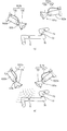
- FIG. 7A Schematic diagram showing an example of the configuration of the microwave processing apparatus according to the first embodiment of the present invention.
- FIG. 10 (a) for explaining the operation of the microwave processing apparatus, and an enlarged view of the main part of the graph of FIG. 10 (a) (FIG. 10 (b)).
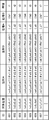
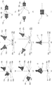
- the figure which shows the model used for the simulation verification test of the microwave processing apparatus (FIG. 11 (a)-FIG. 11 (h)) Plan views showing simulation results of the microwave processing apparatus (FIGS. 12A to 12G) Graphs and tables showing the results of simulation demonstration tests of the microwave processing apparatus (FIGS. 13A to 13D) Schematic diagram showing an example of a microwave processing apparatus according to Embodiment 2 of the present invention (FIG. 14A), and a sectional view taken along line XI-XI of the main part of FIG. 14A (FIG.
- FIG. 14B The figure which shows the model used for the simulation verification test of the microwave processing apparatus (FIG. 15 (a), FIG.15 (b)) The figure which shows the simulation result of the microwave processing apparatus (FIG. 16 (a)-FIG. 16 (g)) The figure which shows the simulation verification test result of the same microwave processing apparatus (FIG. 17 (a)-FIG. 17 (g)) The figure which shows an example of the external appearance of the computer system in embodiment of this invention The figure which shows an example of a structure of the computer system
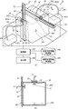
- FIG. 1 is a schematic diagram illustrating an example of a configuration of a microwave processing apparatus 1 according to the present embodiment.
- the microwave processing apparatus 1 includes an irradiation unit 101, a moving unit 102, one or more sensors 103, a situation correspondence information storage unit 104, an irradiation management information storage unit 105, a reception unit 106, and a control unit 107.
- FIG. 1 shows a case where the irradiation unit 101 includes two emission units 12 as an example.
- the irradiation unit 101 includes two microwave oscillators 1011 and two transmission units 1012 that transmit the microwaves generated by the microwave oscillators 1011, respectively.
- a case where one light emitting unit 12 is provided will be described as an example.
- the irradiation unit 101 may have a plurality of emission units 12 as long as it is not two.
- the emission part 12 may be three or more.
- the moving unit 102 of the microwave processing apparatus 1 has two robot arms 1022, and the emitting unit 12 included in the transmission unit 1012 is provided at the tip of each robot arm 1022. This is shown as an example.
- the two microwave oscillators 1011 included in the irradiation unit 101 are referred to as microwave oscillators 1011a and 1011b, and the transmission means 1012 connected to the microwave oscillators 1011a and 1011b are respectively referred to as transmission means 1012a and 1012b.
- the emission units 12 included in the transmission units 1012a and 1012b may be referred to as emission units 12a and 12b.
- the two robot arms 1022 included in the moving unit 102 are referred to as robot arms 1022a and 1022b, and the emission unit 12 installed at the tips of the robot arms 1022a and 1022b is provided with the emission unit 12a and the emission unit 12b, respectively.
- the irradiation unit 101 irradiates microwaves from the plurality of emission units 12.
- the plurality of emitting portions 12 are usually arranged at different positions.
- the irradiation unit 101 may have any configuration as long as it can irradiate microwaves from the plurality of emission units 12.
- the irradiation unit 101 transmits, for example, one or more microwave oscillators 1011 that generate microwaves and microwaves generated by the one or more microwave oscillators 1011, and the microwaves transmitted from the plurality of emission units 12, respectively. It comprises a plurality of transmission means 1012 for emitting waves.
- Each of the plurality of transmission units 1012 includes an emission unit 12 that emits the transmitted microwave.
- each of the plurality of transmission units 1012 is connected to the plurality of microwave oscillators 1011 in a one-to-one relationship, and each transmits a microwave generated by one microwave oscillator 1011. You may do it.
- a plurality of transmission means 1012 may be connected to one microwave oscillator 1011 through a branch structure or the like (not shown).
- Each transmission means 1012 may branch and transmit the microwave generated by the one microwave oscillator 1011.
- the transmission means 1012 connected to one microwave transmitter 1011 and branched into a plurality may be considered as a plurality of transmission means 1012.
- the plurality of emission units 12 are, for example, portions of the plurality of transmission units 1012 that emit microwaves.
- the emitting unit 12 is an antenna, for example.
- the transmission unit 1012 is a combination of a coaxial cable and an antenna that is a plurality of emission units 12 for emitting microwaves connected thereto.
- the end of the coaxial cable that is not connected to the antenna is connected to the microwave oscillator 1011, transmits the microwave generated by the microwave oscillator 1011, and exits from the antenna.
- one transmission unit 1012 includes a coaxial cable 11 connected to the microwave oscillator 1011 and an output unit 12 that is an antenna connected to the coaxial cable 11. Will be described as an example.
- a coaxial tube or a waveguide may be used.
- the waveguide for example, the end portion on the opposite side to the microwave oscillator 1011 side is the emission portion 12.
- the transmission unit 1012a includes the coaxial cable 11a
- the transmission unit 1012b includes the coaxial cable 11b is illustrated as an example.
- the frequencies of the microwaves emitted from the two or more emission units 12 of the irradiation unit 101 are usually the same frequency but may be different frequencies.
- the microwave irradiation by the irradiation unit 101 is, for example, a so-called multi-mode microwave irradiation.
- the plurality of emitting units 12 can emit microwaves at the same time, for example. However, only a part of the plurality of emitting portions 12 may be able to irradiate microwaves at the same time. For example, it is preferable that the plurality of emission units 12 be capable of emitting microwaves at the same time and capable of emitting microwaves even with only a part thereof.
- a coaxial cable, a coaxial tube, and a waveguide that are suitable for the frequency and output of the microwave generated by the microwave oscillator 1011 as the transmission means 1012.
- the antenna that is the emission unit 12.
- the structure of the antenna used as the emitting portion 12 is not limited as long as it can emit microwaves.
- the antenna is a planar antenna, a parabolic antenna, a horn antenna, or the like.
- the antenna may be an antenna having directivity or an antenna having no directivity.
- each output part 12 it is preferable to use an antenna with high directivity.
- an antenna having a gain of 10 dB or more is preferably used as a highly directional antenna.
- the antenna used as the emitting unit 12 is, for example, an antenna with a coaxial waveguide converter.
- the antenna is connected to the coaxial cable 11 via a coaxial waveguide converter (not shown) included in the antenna itself.
- a waveguide (not shown) is usually provided between the antenna portion of the antenna with the coaxial waveguide converter and the coaxial waveguide converter.
- FIG. 1 the example which used the pyramid horn antenna as the output part 12 is shown.
- the microwave transmitter 1011 may have any structure as long as it can generate microwaves.
- the microwave oscillator 1011 is, for example, a semiconductor type oscillator.
- the semiconductor oscillator is a microwave oscillator that generates a microwave constituted by using a semiconductor element.
- the microwave oscillator 1011 may be a microwave oscillator such as a magnetron, a klystron, or a gyrotron.
- the frequency and intensity of the microwave emitted from the microwave oscillator 1011 are not limited.
- the frequency of the microwave emitted from each microwave oscillator 1011 may be, for example, 2.45 GHz, 5.8 GHz, 24 GHz, 915 MHz, or other The frequency may be in the range of 300 MHz to 300 GHz.
- the frequencies of the microwaves emitted by the two or more microwave oscillators 1011 are usually the same frequency, but may be different.
- the intensity of the microwaves emitted by the two or more microwave oscillators 1011 may be the same or different.
- a power source used when the microwave oscillator 1011 outputs microwaves may be included in each microwave oscillator 1011 or may be included in a microwave processing apparatus. Alternatively, the power source or the like may be provided outside the microwave processing apparatus. Further, the microwave oscillator 1011 may include an amplifier or the like.
- the phases of the microwaves emitted from the plurality of emission units 12 may be the same phase or different phases. Moreover, when it has the 3 or more output part 12, the output part 12 of the same phase and the output part 12 of a different phase may be mixed.
- each branched microwave is a separate amplifier.
- each amplifier may be considered as a separate semiconductor oscillator.
- the irradiation unit 101 can control the phase of the microwaves emitted from the plurality of emission units 12.
- the irradiation unit 101 is preferably capable of individually controlling the phases of microwaves emitted from the plurality of emission units 12, for example.
- a group constituted by two or more emission units 12 among the plurality of emission units 12 may be controllable in units of groups.
- the phase of the irradiation unit 101 is controlled by the control unit 107, for example.
- the irradiation unit 101 is preferably controllable so that, for example, at least a part of the plurality of emission units 12 generates a microwave having a phase different from that of the other emission units 12.
- the emission unit 101 may be controlled so that the phases of the microwaves emitted from the plurality of emission units 12 are in phase shift.
- the phase control may be considered as control of the initial phase, for example.
- the irradiation unit 101 can control the phase of the microwaves emitted from the plurality of emission units 12.
- the irradiation unit 101 includes a plurality of microwave oscillators 1011
- the phase irradiated from the emission unit 12 can be controlled by controlling the phase of the microwave generated by the microwave oscillator 1011 by the control unit 107 described later.
- the phases of the plurality of microwave oscillators 1011 may be appropriately synchronized, for example, by synchronizing the phases between the microwave oscillators 1011 or by outputting a signal or the like for synchronization by the control unit 107 or the like. That's fine.
- a microwave oscillator provided with a phase shifter (not shown) for controlling the phase may be used.
- the microwave oscillator 1011 is a semiconductor oscillator having an oscillator and an amplifier (not shown), a semiconductor oscillator having a phase shifter between the oscillator of the semiconductor oscillator and the amplifier, or a stage subsequent to the amplifier.
- a semiconductor oscillator to which a phase shifter is connected may be used as the microwave oscillator 1011 capable of controlling the phase. Further, instead of using a microwave oscillator capable of controlling the phase, a phase shifter (not shown) for controlling the phase of the microwave generated by each microwave oscillator is provided in the middle of the transmission means 1012 or before and after. You may make it provide. In this case, the phase of the generated microwave is controlled by controlling each phase shifter by the control unit 107 described later.
- the irradiation unit 101 has one or more configurations that transmit the microwave generated by one microwave oscillator 1011 to the plurality of transmission units 1012 through a branch structure or the like, one microwave oscillator
- the microwave generated by 1011 is branched into a plurality of waves, and the branched microwaves are input to a phase shifter (not shown) to control each phase, and the microwaves whose phases are controlled are respectively transmitted to a plurality of transmission units 1012. You may make it transmit.
- the phase shifter is disposed downstream of the one microwave oscillator 1011. (Not shown), and the microwaves whose phases are controlled by the phase shifter are branched and transmitted to the plurality of transmission units 1012, and are transmitted to and output from the plurality of transmission units 1012. Wave phase can be controlled simultaneously.
- phase shifter Since the structure of the phase shifter is a known technique, a detailed description is omitted here.
- phase shifter see, for example, the following documents. "" High-frequency circuit classroom [V. Control circuit] ", [online], iLab, [March 11, 2016 search], Internet ⁇ URL: http://www1.sphere.ne.jp/i-lab/ilab/kairo/k5/k5_3a .Htm> ".
- phase when controlling the phase, it is preferable to use a semiconductor oscillator composed of a semiconductor element as the microwave oscillator because the phase can be easily controlled.
- the irradiation unit 101 may be capable of irradiating microwaves having two or more different frequencies, for example.
- the irradiation unit 101 may irradiate two or more different frequencies of microwaves before and after the change by changing the frequency of the microwaves emitted by the one or more emission units 12. Further, two or more of the plurality of emitting units 12 of the irradiation unit 101 may emit microwaves having different frequencies by emitting microwaves having different frequencies. In this case, for example, by moving the emission unit 12 and changing the emission unit 12 that irradiates microwaves to one region to the emission unit 12 that emits microwaves of different frequencies, two or more different frequency micros Waves can be applied to one area.
- the frequency of the microwave irradiated by each emitting unit 12 of the irradiation unit 101 is controlled by the control unit 107 described later, for example.
- the irradiation unit 101 is controlled by a control unit 107 (to be described later) to irradiate a microwave having a frequency corresponding to the situation information (to be described later).
- the irradiation unit 101 irradiates microwaves of two or more different frequencies by changing the frequency of the microwaves emitted by the emission unit 12, how the emission unit 12 irradiates microwaves of different frequencies It doesn't matter if you can do it.
- the irradiation unit 101 uses, as the microwave oscillator 1011, one or more semiconductor-type oscillators in which the frequency of the generated microwave is variable, and the microwave frequency generated by the one or more semiconductor-type oscillators 1011 is changed. By changing, it may be possible to irradiate microwaves of two or more different frequencies from the emission part 12.
- the irradiation unit 101 has, for example, a plurality of semiconductor oscillators (not shown) having different frequencies of generated microwaves, and generates one of the plurality of semiconductor oscillators.
- microwaves with different frequencies may be emitted from the plurality of emitting units 12. Since the semiconductor oscillator in which the frequency of the generated microwave is variable is a known technique, detailed description thereof is omitted here.
- a semiconductor oscillator capable of changing the frequency for example, the one shown in the following URL is known.
- the frequency of the microwave generated by the microwave oscillator 1011 which is a semiconductor oscillator is controlled by, for example, the control unit 107 described later.
- the principle of frequency control of the semiconductor type oscillator refer to the following URL, for example. “Http://cp.literature.agilent.com/literweb/pdf/00-2564.pdf”, “http://toragi.cqpub.co.jp/Portals/0/backnumber/2004/01/p098-099” .Pdf "," http://www.altima.jp/column/fpga_edison/vco_vcxo.html ".
- the microwave oscillators 1011a and 1011b are semiconductor oscillators having a variable frequency of generated microwaves and having a phase shifter (not shown) for controlling the phase. A case will be described as an example.
- the moving unit 102 individually moves the plurality of emitting units 12 included in the irradiation unit 101. It may be considered that the movement is performed independently of the movement. For example, the moving unit 102 individually moves the emitting units 12 (for example, antennas) included in each of the plurality of transmission units 1012. The moving unit 102 may individually move the emitting unit 12 included in the transmission unit 1012 by individually moving the transmission unit 1012 included in the irradiation unit 101, for example. For example, the moving unit 102 may individually move the end portions that are the emission units 12 of the plurality of waveguides (not shown) included in the irradiation unit 101.
- the movement of each emitting unit 12 may be a one-dimensional movement (for example, a movement in a linear direction), a two-dimensional movement (for example, a movement in a plane, etc.), or a three-dimensional direction. (For example, movement in a space). Moreover, you may think that the movement here also includes the change of the direction of the emission part 12.
- FIG. The direction of the emission part 12 is, for example, a change in the emission direction of the microwave, rotation around the emission direction, or the like.
- the movement here may be a combination of movement in the one-dimensional to three-dimensional directions and change in the irradiation direction.
- the change in the irradiation direction of the emission unit 12 may be, for example, a change in the direction of the antenna that is the emission unit 12.
- the moving unit 102 may have two or three or more robot arms 1022.
- the plurality of robot arms 1022 are, for example, robot arms 1022 that can move independently.
- the robot arm is also called a manipulator.
- the robot arm 1022 moves a tip or the like by a plurality of arms connected by a plurality of joints respectively driven by actuators such as a plurality of motors.
- the robot arm 1022 may be any robot arm.
- the robot arm 1022 is, for example, a vertical articulated robot arm or a horizontal articulated robot arm.
- the robot arm 1022 has a high degree of freedom of movement, for example, the robot arm 1022 is preferably an n-axis (n is an integer of 6 or more) robot arm.
- the moving unit 102 may be configured by only a plurality of robot arms 1022 or may have other configurations.
- the size of the robot arm 1022 does not matter. Further, the size ratio between the robot arm 1022 and the emission unit 12 installed on the robot arm 1022 is not limited. Since control of the robot arm and the posture and movement of the robot arm is a known technique, detailed description thereof is omitted here.
- the emission units 12 (for example, antennas) of the plurality of transmission units 1012 are respectively installed on the plurality of robot arms 1022 included in the moving unit 102, and the emission units arranged on the robot arms 1022 by moving the robot arms 1022.
- the part 12 can be moved.
- each emitting unit 12 attached to the robot arm 1022 can be moved individually.
- the emitting unit 12 is installed at, for example, a so-called hand, a hand effector (not shown) or a tip of each robot arm 1022. Even when the emitting unit 12 is gripped by a gripping unit (not shown) provided at the hand of the robot arm 1022 or the like, it is assumed here that the emitting unit 12 is installed on the robot arm 1022. Good.
- the transmission means 1012 has a waveguide
- the robot arm 1022 is provided with the emitting portion 12 which is the end of the waveguide, and the end of the waveguide is moved by moving the robot arm 1022. You may make it move.
- the moving unit 102 preferably has the same number of robot arms 1022 as the number of emitting units 12 included in the irradiation unit 101.
- the moving unit 102 has at least two or more robot arms 1022, as long as the emitting units 12 respectively installed on the two or more robot arms 1022 can be individually moved. May be.
- the emitting unit 12 of the transmission means 1012 is installed on the robot arm 1022 of the moving unit 102, and a coaxial cable other than the emitting unit 12, a microwave oscillator 1011 or the like is installed in a place other than the robot arm 1022. Also good.
- a transmission unit 1012 having the emission unit 12, a microwave oscillator 1011 to which a microwave is transmitted by the transmission unit 1012, and the like may be appropriately installed on the robot arm 1022 in which the emission unit 12 is installed.
- the configuration of the irradiation unit 101a may be installed in the robot arm 1022a of the moving unit 102, and the configuration of the irradiation unit 101b may be set in the robot arm 1022b.
- a robot other than the robot arm 1022 a moving object such as a crane, a so-called drone that can be remotely operated, a moving object that moves on a rail, or the like may be used.
- the situation information is information indicating a situation related to a region irradiated with the microwaves emitted from the plurality of emission units 12.
- the region here is a concept including, for example, a three-dimensional space.
- the status information may be information indicating the status of one or more desired locations in the region irradiated with the microwave, or information indicating the status of the irradiation object irradiated with the microwave. Good.
- the desired location here is a location where electric fields due to a plurality of microwaves emitted from a plurality of emission sections 12 are concentrated, a location where a plurality of microwaves are strengthened by interference, or the phase of incident microwaves is the same phase. And the like.
- the region irradiated with the microwaves here is preferably a region where the microwaves emitted from the plurality of emission units 12 overlap.
- the situation related to the region irradiated with the microwave is, for example, the temperature, pressure, humidity, and conductivity in the region. Further, the situation related to the region irradiated with the microwave is a value indicating the load state of the device (for example, when a device such as a stirring blade (not shown) is provided in the region irradiated with the microwave (for example, The torque at the time of rotation of the stirring blade may be used.
- the situation of the region irradiated with the microwave may be considered to include the situation of the object to be irradiated with the microwave (not shown) and the situation of one or more places irradiated with the microwave.
- the condition of the region includes, for example, the temperature, viscosity, pH, color, concentration, moisture (water content), sugar content, conductivity, and the like of the region.
- the one or more sensors 103 include a temperature sensor, a specific gravity sensor, a pressure sensor, a concentration sensor, a color sensor, a stirring torque sensor, a humidity sensor, a pH sensor, a conductivity sensor, a viscosity sensor, a moisture sensor, and a sugar content sensor. One or more of them.
- the irradiation object will be described later.
- the status information acquired by the sensor 103 includes so-called raw data such as an output value of an electric signal acquired by the sensor 103, or a value representing a measurement target (for example, temperature, pressure, conductivity, moisture content, etc.). Measured value such as a value replaced with (value), or a binary value such as “high” or “low”.
- the binary value may be, for example, a value acquired by determining whether or not the measured value is higher than a predetermined threshold value for the sensor 103.
- each sensor 103 may be the same sensor (for example, the same temperature sensor) or a different sensor.
- the position where one or more sensors 103 are provided is not limited.
- a case where one sensor 103 that is an infrared image sensor for detecting a temperature distribution is provided so that a region where microwaves irradiated from a plurality of emitting units 12 overlap is a detection target region. It is shown as an example.
- the sensor 103 may be any sensor, and the position where the sensor 103 is provided, the number of the sensors 103, the shape of the sensors 103, and the like are not limited.
- the situation correspondence information storage unit 104 stores one or more situation correspondence information.
- the situation correspondence information includes information specifying two or more ranges of values indicated by the one or more situation information acquired by the one or more sensors 103, and the microwaves irradiated by the irradiation units 101 respectively corresponding to the two or more ranges. This is information having frequency and information.
- the information specifying the range of one value is, for example, information having at least one of an upper limit value and a lower limit value. For example, when the information specifying the range of one value has one upper limit value, the one value range may be considered as a range less than (or less than) the one upper limit value.
- the range of the one value when information specifying a range of one value has a lower limit value, the range of the one value may be considered as a range greater than or equal to the lower limit value (or above the lower limit value).
- the information specifying the range of 2 or more of the value may be one threshold value.
- the range of the value of the threshold value or more is the first range, and the range of the value less than this threshold value. May be considered as the second range.
- the two or more ranges are non-overlapping ranges, for example.
- the range including two or more ranges is preferably a range including a range of values that can be acquired by one or more sensors 103.
- one range specified by the information specifying the range may include information specifying the range for each of two or more different situation information.
- the situation correspondence information may be stored in the situation correspondence information storage unit 104 in association with the situation information (for example, in association with an identifier or the like of the situation information).
- the situation correspondence information storage unit 104 may be a non-volatile recording medium or a volatile recording medium. The same applies to other storage units. If the situation correspondence information is not used, the situation correspondence information storage unit 104 may be omitted.
- the irradiation management information storage unit 105 stores one or more irradiation management information.
- One irradiation management information is, for example, (1-A) information having a plurality of emission position information and target position information. Further, one irradiation management information is stored in association with the order in which one or more sets of a plurality of emission position information indicating the positions of (1-B) the plurality of microwave emission units 12 are moved. It may be information.
- the irradiation management information is any of the above information will be described.
- the irradiation management information is information having a plurality of emission position information and target position information
- the plurality of emission position information is information indicating the positions of the plurality of emission units 12 included in the irradiation unit 101, respectively.
- the emission position information is information indicating the position of the emission unit 12, for example, the coordinates of the emission unit 12.
- the emission position information may further include information indicating the direction of the emission unit 12.
- the information indicating the direction is, for example, information indicating the irradiation direction of the microwave as described above, information indicating a rotation angle of the emission unit 12 with respect to the irradiation direction, or the like.
- the information indicating the irradiation direction is, for example, a direction vector or a combination of an azimuth angle and an elevation angle.
- the emission position information includes information indicating the irradiation direction. It is preferable to have.
- the emission position information may not include information indicating the direction.
- the one emission position information is information associated with one emission unit 12.
- each piece of emission position information included in one piece of emission management information is stored in one piece of irradiation management information in association with information specifying the emission unit 12 associated with each piece of emission position information.
- the information for specifying the emission part 12 is referred to as emission part specifying information.
- the emission unit specifying information is, for example, information for specifying a movable part of the moving unit 102 where the emission unit 12 is installed.
- the emission part specifying information is an identifier of the emission part 12.
- the identifier of the emitting unit 12 is, for example, a code assigned to the emitting unit 12.
- the emission unit specifying information is information for specifying the robot arm 1022 of the moving unit 102 where the emission unit 12 is installed, for example, an identifier of the robot arm 1022 or the like.
- the identifier of the robot arm 1022 is, for example, a code assigned to the robot arm 1022 or address information such as an IP address.
- the target position information is information indicating a position to be irradiated with microwaves.
- the microwave irradiation target is, for example, a location where the electric field due to the microwaves emitted from the plurality of emission units 12 is concentrated, a location where the microwaves emitted from the plurality of emission units 12 are strengthened by interference,
- the positions of the microwaves irradiated from the emission unit 12 are the same phase, and the position indicating the irradiation target is a position indicating these positions.
- the plurality of emission position information included in one irradiation management information is, for example, for concentrating the electric fields generated by the microwaves emitted from the plurality of emission units 12 at the position indicated by the target position information included in the same irradiation management information, or This is information indicating the position of each emitting portion 12 for increasing the intensity.
- the phase of the microwaves emitted from each emission unit 12 is a predetermined phase, for example.
- the irradiation management information is information stored in association with the order in which one or more sets of a plurality of emission position information are moved, the details of the emission position information and the plurality of emission position information Can be stored in association with the emission part specifying information, as described above.
- the order in which the movement is performed is, for example, the order in which the moving unit 102 moves the plurality of emitting units 12 under the control of the control unit 107.
- the order in which the movement is performed may be considered as the order in which microwave irradiation or processing is performed.
- the fact that one or more sets of emission position information are stored in association with the order in which movement is performed means that, for example, they are arranged and stored in the order in which movement is performed so that they are read out in the order in which movement is performed. It may be stored in association with a value such as a serial number indicating the order in which movement is performed.
- one set of the plurality of emission position information may further include information indicating the timing at which the movement is started, the time when the movement is stopped after the movement according to the one irradiation management information, and the like. good.
- one or more pieces of irradiation management information may further include a plurality of phase designation information.
- the plurality of pieces of phase designation information are information indicating phases when the plurality of emission units 12 each emit microwaves.
- the information indicating the phase is, for example, information indicating the phase difference with respect to the reference microwave or information indicating the initial phase.
- the phase designation information is stored in the irradiation management information in association with information indicating the corresponding emission unit 12.
- the phase designation information may be stored in the irradiation management information in association with the emission position information associated with the information indicating the corresponding emission unit 12.
- the irradiation management information stored in the irradiation management information storage unit 105 is the acquired information.
- the irradiation management information used in the above (1-A) uses a set of emission position information of each of a plurality of predetermined emission units 12 and a set of the emission position information. Or information having target position information calculated by a predetermined mathematical formula or the like. Further, the irradiation management information used in (1-A) is performed by using each of a predetermined set of emission position information of the plurality of emission units 12 and a set of emission position information. Information including target position information indicating a position where the intensity of the electric field or magnetic field obtained by a predetermined simulation for acquiring the electric field distribution or the magnetic field distribution is high.
- the irradiation management information used in the above (1-B) uses information such as coordinates indicating the position of this location in order to concentrate the electric field by the microwave at one or more predetermined locations. This is information having the emission position information of the plurality of emission units 12 calculated in the above manner.
- the irradiation management information used in (1-B) includes a plurality of emission units 12 respectively acquired by simulation or experiment in order to concentrate the electric field by the microwave at one or more predetermined locations. This is information having a set of emission position information.
- the irradiation management information used in (1-B) is stored in the irradiation management information storage unit 105 in association with the irradiation order of the location where the microwave is irradiated.
- the group here is a combination which does not overlap, for example.
- the situation of irradiating microwaves includes, for example, the environment for irradiating microwaves, the shape of an antenna for irradiating microwaves, and the like.
- the distribution of the electric field and magnetic field due to the microwave is affected by the reflected wave, so an accurate electric and magnetic field distribution is predicted.
- microwave irradiation management information using simulation as mentioned above.
- the case where microwave irradiation is performed in an environment where microwave reflection or the like occurs is a case where the microwave processing apparatus performs microwave irradiation in a container or a closed space as described later. .
- the irradiation management information storage unit 105 may be omitted.
- the reception unit 106 receives position designation information.
- the position designation information is information indicating a position to be irradiated with microwaves.
- the position to be irradiated with microwaves is, for example, a position to be irradiated with microwaves emitted from the plurality of emitting units 12.
- the position to be irradiated with the microwave is, for example, a desired location. Further, the location here may be considered as one point, or may be considered as a region having a predetermined size or the like. The same applies to the following.
- one point is a point that can be designated by one coordinate, for example.
- the position to be irradiated with the microwave is, for example, a place where the microwave is locally heated.
- the position to be irradiated with the microwave is, for example, a place where it is desired to increase the electric field strength by the microwave.
- the position to be irradiated with the microwave is, for example, a place where the microwaves respectively emitted from the plurality of emission units 12 are desired to be strengthened by interference.
- the position to be irradiated with the microwave is, for example, a location where the electric fields generated by the microwaves emitted from the plurality of emission units 12 are concentrated.
- the position to be irradiated with the microwave is, for example, a place where the microwaves emitted from the plurality of emission units 12 are to be in phase.
- “Reception” here refers to, for example, reception from an input means by a user, reception of an input signal transmitted from another device, reading of information from a recording medium, or the like.
- the position specifying information input means may be anything such as a numeric keypad, a keyboard, a mouse, or a menu screen.
- the receiving unit 106 can be realized by a device driver for input means such as a keyboard, control software for a menu screen, or the like.
- the control unit 107 controls the movement of the emitting unit 12 by the moving unit 102.
- the control unit 107 transmits a control signal or the like to the moving unit 102 to operate the moving unit 102 and individually control the movement of each emitting unit 12 installed in the moving unit 102.
- Operating the moving unit 102 means, for example, moving the position of the moving unit 102 or changing the posture of the moving unit 102. Controlling the movement of each emission part 12 may be considered as moving each emission part 12, for example.
- the control unit 107 controls the moving unit 102 to operate the moving unit 102 to move each emitting unit 12 individually.
- the control unit 107 transmits a control signal or the like to each robot arm 1022, and each By operating the robot arm 1022 individually, each emitting unit 12 can be moved individually.
- the control of each robot arm 1022 may be considered as the control of the moving unit 102.
- the movement is a concept including moving the direction of the emission part 12 so that the emission direction of the emission parts 12a and 12b becomes a desired direction.
- the operation of the robot arm 1022 is, for example, movement of the robot arm 1022 or change of posture.
- control unit 107 transmits a control signal to operate the robot arms 1022 a and 1022 b included in the moving unit 102, so that the emission units installed in the robot arm 1022 a and the robot arm 1022 b respectively. 12a and 12b can be moved to a desired position.
- control unit 107 reads data for moving the emitting unit 12 stored in advance in a storage unit (not shown) to a desired position, and moves the moving unit so that the emitting unit 12 moves to the position indicated by the data. 102 is controlled.
- This data is, for example, irradiation management information stored in the irradiation management information storage unit 105.
- the storage unit (not shown) can store this one such as irradiation management information.
- the control unit 107 stores the coordinates indicating the movement destination of the emission unit 12 and information indicating the emission direction after movement (for example, information having an azimuth angle and an elevation angle, a direction vector, and the like) in advance.
- information indicating the coordinates of the movement destination and the emission direction is read from a storage unit (not shown), and the position and direction of the tip of the robot arm 1022 are indicated by the read coordinates and direction vectors of the movement destination.
- Information for controlling the robot arm 1022 so as to be in the coordinates and direction is calculated from the information indicating the coordinates of the movement destination and the emission direction that have been read out, and using this information, By operating the arm 1022 can be moved one of the exit portion 12 in a desired position.
- the information for controlling the robot arm 1022 calculated from the information on the coordinates of the movement destination and the direction vector of the emitting unit 12 described above is, for example, information for controlling the position of the arm constituting the robot arm 1022 and the like. Specifically, the information is information for controlling a plurality of actuators and the like constituting the robot arm 1022.
- the process of calculating information for controlling the robot arm 1022 from information such as coordinates and direction vectors indicating the position of the movement destination of the tip of the robot arm 1022 is a known technique as a technique for controlling the robot arm 1022 or the like. Therefore, detailed description is omitted here.
- the control unit 107 controls, for example, the moving unit 102 to move one or two or more emission units 12 so that the microwaves emitted from the plurality of emission units 12 of the irradiation unit 101 overlap at least at a desired location.
- the control unit 107 controls and operates the moving unit 102 (for example, one or more robot arms 1022 included in the moving unit 102), and at least microwaves emitted from the plurality of emitting units 12 are desired.
- One or two or more emission units 12 are individually moved so as to overlap each other.
- by individually moving the plurality of emission units 12 it is possible to irradiate the microwaves emitted from the plurality of emission units 12 in a desired location.
- heating that combines a plurality of microwave irradiations for example, local heating or uniform heating, which cannot be performed by one microwave irradiation, can be performed on a desired location. It becomes possible.
- control unit 107 controls the moving unit 102 to set the one or more emission units 12 so that the microwaves emitted from the plurality of emission units 12 of the irradiation unit 101 are strengthened by interference at a desired location.
- Move For example, the control unit 107 controls and operates the moving unit 102 (for example, one or more robot arms 1022 included in the moving unit 102), and the microwaves irradiated from the plurality of emitting units 12 are in desired locations. 1 or 2 or more of the emitting portions 12 are individually moved so as to strengthen each other by interference. Thereby, the local heating in the desired location which cannot be performed by one microwave irradiation can be performed.
- the desired location here is one or more desired locations in the area
- the desired location is one or more desired locations in the area
- control it is preferable that between this desired location and each output part 12 is a space with a high microwave permeability, for example, a space having a substance with a low dielectric constant. The same applies to the following.
- control unit 107 controls, for example, the moving unit 102 to move one or more emitting units so that the electric fields due to the microwaves irradiated from the plurality of emitting units 12 are concentrated at a desired location.
- the electric field generated by the microwave may be considered as, for example, an electric field generated by the microwave or an electric field of the microwave itself generated by the presence of the microwave microwave.
- the concentration of the electric field means, for example, an increase in electric field strength, an increase in electric field strength distribution, and the like.
- the concentration of the electric field means, for example, that the electric field is concentrated or the distribution of the electric field strength is higher than in the case where the positions of the plurality of emitting portions 12 are not moved.
- the position here may be considered to include the direction.
- control unit 107 controls and operates the moving unit 102 (for example, one or more robot arms 1022), and the electric field generated by the microwaves emitted from the plurality of emitting units 12 is concentrated at a desired location.
- One or more emitting parts 12 are moved. This makes it possible to perform local heating at a desired location, which cannot be performed by one microwave irradiation.
- control unit 107 controls the moving unit 102 to move each emitting unit so that the phase of the microwave incident on a desired location becomes the same phase.
- control unit 107 controls and moves the moving unit 102 (for example, one or more robot arms 1022), and a plurality of microwaves incident on a desired location from the plurality of emitting units 12 are the same.
- One or two or more emission parts 12 are moved so as to be in phase. This makes it possible to perform local heating at a desired location, which cannot be performed by one microwave irradiation.
- FIG. 2 is a schematic diagram for explaining control for moving a plurality of emitting units 12 included in the irradiation unit 101.
- Control for moving the emission unit 12 may be considered as control of the position of the emission unit 12.
- the irradiating unit 101 includes five emitting units 12 (referred to here as emitting units 12a to 12e) such as antennas.
- the output frequencies of the microwaves generated by the emission units 12a to 12e are the same, and the phase of the emitted microwaves is also the same phase. To do. It is assumed that the desired portion 1021 is located in a region where microwaves emitted from the plurality of emission units 12 overlap.
- the distances between the emission parts 12a to 12e before movement and the desired location 1021 are distances Ka to Ke, respectively.
- the position of the desired location 1021 is set so that the distances Ka to Ke have different values. 2 may be considered to be the same or different from the emission parts 12a and 12b in FIG.
- each emitting unit The positions of the emitting portions 12a to 12e may be controlled so that the phase difference caused by the difference in distances Ka to Ke between 12a to 12e and the desired location 1021 becomes zero.
- the distance from one emitting section 12 serving as a reference among the plurality of emitting sections 12 to the desired location 1021 and the distance between each emitting portion 12a to 12e and the desired location 1021 The difference is calculated, and the difference is divided by the wavelength of the microwaves emitted from each of the emission parts 12a to 12e to obtain remainders ⁇ a to ⁇ e ( ⁇ ).
- the emitting portions 12a to 12e are moved in the direction of the desired location 1021. That is, it is brought close to the desired location 1021.
- the calculation of the above-described phase difference may not be performed for the single emission unit 12 serving as a reference, the phase of the single emission unit 12 serving as a reference may not be changed, and the phase difference may be set to zero. Also good.
- the emission unit 12 serving as one reference is the emission unit 12c
- the difference between the distance Ka and the distance Kc, that is, Ka ⁇ Kc is calculated, and this difference is calculated as the wavelength of the microwave emitted by the emission unit 12.
- the remainder ⁇ a ( ⁇ a ⁇ ) is obtained by dividing by ⁇ , and the moving unit 102 is controlled to move the emitting unit 12a closer to the desired location 1021 by the value of the remainder ⁇ a.
- the difference between the distance Kb and the distance Kc that is, Kb ⁇ Kc is calculated, and the difference is divided by the wavelength ⁇ of the microwave to obtain a remainder ⁇ b ( ⁇ b ⁇ ), and the moving unit 102 is controlled.
- the emission unit 12b is moved so as to approach the desired location 1021 by the distance of ⁇ b.
- the moving unit 102 is controlled to output only the distances ⁇ d and ⁇ e.
- the portion 12d and the emitting portion 12e are moved so as to approach the desired location 1021.
- the above moving distance is a phase based on the distance between the emitting portion 12c and the desired location 1021. For this reason, it is not necessary to calculate the distance difference as described above for the emission unit 12c, and the position of the emission unit 12c need not be changed, for example.
- any output part 12 is good also as a reference
- the control unit 107 consequently positions each emitting unit 12 so that this relative remainder is eliminated. If it can be changed, the position of each emitting unit 12 may be moved by controlling the moving unit 102. For example, when the remainder of the emission unit 12a with respect to the emission unit 12c is a certain value ⁇ , the control unit 107 controls the moving unit 102 to move the emission unit 12a closer to the desired location 1021 by ⁇ . Alternatively, the emitting portion 12a may be moved closer to the desired location 1021 by 1 / 3 ⁇ , and the emitting portion 12c may be moved away from the desired location 1021 by 2 / 3 ⁇ . The same applies to the following.
- control unit 107 controls the movement unit 102 so that the distances Ka to Ke are set to the wavelengths ⁇ of microwaves generated by the respective emission units 12a to 12e.
- Each of the emitting portions 12a to 12e is moved closer to the desired location 1021 by the distance indicated by the remainders ⁇ a to ⁇ e obtained by dividing by. However, ⁇ a to ⁇ e are all less than ⁇ .
- each emission unit after movement so that each location has the same phase has been described as an example.
- the positions 12a to 12e may be determined.
- a position where a plurality of locations are in phase cannot be determined.
- a desired location can be locally heated.
- microwave oscillators 1011 may be two or more, and if it is two or more, the same control as described above can be realized. is there.
- each emitting section 12 may be moved so that microwaves having the same phase are irradiated from a plurality of emitting sections 12 at a desired location. For example, assuming that the phase of the emission part 12b is delayed by ⁇ with respect to the emission part 12a, first, assuming that the positions of the emission part 12a and the emission part 12b are irradiated with microwaves of the same phase.
- the position may be determined as described above, and the position of the emitting portion 12b may be brought closer to a desired location by the amount of the phase difference ⁇ .
- the position of the emitting portion 12b may be moved in the direction of a desired location by ⁇ from the position determined as the same phase.
- control unit 107 controls the moving unit 102 to output a plurality of emission points so that one or two or more desired locations become positions that are strengthened by interference of microwaves emitted from the emission units 12.
- the position where the unit 12 is moved may be determined by a method other than the above. For example, by changing the positions of the plurality of microwave oscillators 1011 and performing simulations, experiments, or the like, the positions of the plurality of emission units 12 where the microwaves strengthen each other at a desired location may be determined. Similarly, the positions of the plurality of emitting portions 12 that uniformly heat a desired region may be determined by simulation or the like.
- the region here is a concept including a three-dimensional space. Further, the positions and the like of the plurality of emitting portions 12 that can heat the desired region evenly may be determined by simulation.
- control unit 107 uses the irradiation management information stored in the irradiation management information storage unit 105 to irradiate the irradiation unit 101 from the plurality of emission units 12.
- An example of controlling the phase of the microwave will be described.
- the control unit 107 when using the irradiation unit 101 that can control the phase of the microwaves emitted from the plurality of emission units 12, the control unit 107 further includes the irradiation unit 101 having a plurality of emission units 12. You may make it control the phase of the microwave irradiated from.
- the control unit 107 individually controls the movement of one or more emission units 12 of the irradiation unit 101 and individually controls the phases of the microwaves that the irradiation unit 101 emits from the plurality of emission units 12. It may be.
- the control unit 107 individually controls one or more microwave oscillators 1011 that can control the phase, thereby changing the phase of the microwaves generated by the one or more microwave oscillators 1011.
- the microwaves whose phases are changed may be irradiated from the plurality of emitting units 12.
- a phase shifter (not shown) for controlling the phase of the microwaves transmitted by the one or more transmission units 1012 provided for the one or more transmission units 1012 included in the irradiation unit 101 is individually controlled.
- the phase of the microwaves transmitted to the transmission unit 1012 may be controlled so that the microwaves whose phases have been changed may be emitted from the plurality of emission units 12.
- the irradiation unit 101 controls the phase of the microwaves emitted from the plurality of emission units 12.
- control unit 107 controls the irradiation unit 101 to control the phases of the microwaves emitted from the plurality of emission units 12, thereby changing the phases of the microwaves emitted from the plurality of emission units 12 to different phases. Can be the same phase.
- the phase control is, for example, to advance or slow down the phase of the generated microwave.
- the phase control may be considered as, for example, controlling or setting the initial phase of the microwaves emitted from the respective emission units 12.
- the control of the phases emitted by the plurality of emission units 12 may be, for example, relative control of the phases of the microwaves emitted by the plurality of emission units 12 or absolute control.
- the location where the electric field is concentrated by the microwave can be controlled as will be described later. Since the configuration and the control method for the control unit 107 to control the phase of the microwave oscillator 1011 are known techniques, detailed description thereof is omitted here.
- the control unit 107 controls the irradiation unit 101 so that, for example, at least some of the plurality of emission units 12 emit microwaves having different phases. It may be considered that the control unit 107 controls the microwave oscillator 1011 and the phase shifter (not shown) included in the irradiation unit 101 or the like. As long as at least a part of the phases can be emitted, it does not matter what kind of phase the control unit 107 controls the irradiation unit 101 to irradiate each of the plurality of emission units 12. For example, the control unit 107 controls the irradiation unit 101 so that three or more emission units 12 generate microwaves having two or more different phases.
- control unit 107 irradiates the irradiation unit 101 so that a part (except all) of the plurality of emission units 12 generates microwaves having the same phase and the remaining emission units 12 generate microwaves having different phases. May be controlled.
- control unit 107 may control the microwave oscillator 1011a and the microwave oscillator 1011b to have different phases in the microwave processing apparatus 1 illustrated in FIG.
- the control unit 107 adjusts the phase of the microwaves emitted from the plurality of emission units 12 by the irradiation unit 101 so that the electric fields generated by the microwaves emitted from the plurality of emission units 12 are concentrated at one or more desired locations.
- the concentration of the electric field means, for example, that the electric field strength is increased.
- the concentration of the electric field means that the electric field is concentrated as compared with the case where the phase of the microwaves irradiated from the plurality of emitting units 12 is not controlled, for example.
- a microwave with a random phase is generated.
- the case where the phase of the microwave is not controlled may be considered to mean such a case.
- control unit 107 is configured such that the irradiation unit 101 irradiates the microwaves from the plurality of emission units 12 so that one or two or more desired locations are positions where the microwaves radiated from the plurality of positions are strengthened by interference.
- the phase may be controlled.
- the position where the microwaves are strengthened by interference may be considered as, for example, a position where the intensity of the microwaves is strengthened by interference. Reinforcement of microwaves may be considered as an increase in amplitude, for example.
- the position where the microwaves are strengthened by interference is, for example, a position where an electric field having at least a higher intensity than that obtained individually from each of the plurality of irradiated microwaves is obtained.
- the position where the microwaves are strengthened by interference may be, for example, a position where a plurality of microwaves are not weakened by interference. However, the height of the wave in a desired location is not ask
- the irradiation unit 101 emits from the plurality of emission units 12 so that one or two or more desired locations are positions where the microwaves irradiated from the plurality of emission units 12 are most strongly strengthened by interference. It is preferable to control the phase of the microwave. With such a configuration, it is possible to concentrate the microwaves irradiated from the plurality of emission units 12 at one or more desired locations. Thereby, it becomes possible to selectively heat one or more desired locations.
- control unit 107 is a position where one or more desired locations are positions where two or more of the microwaves irradiated from the three or more emission units 12 are most strengthened by interference, and the remaining microwaves are By controlling the phase of the microwaves emitted from the three or more emission parts 12 so that the two or more microwaves that are most strengthened are at least not weakened, a desired portion is strengthened by interference. You may do it.
- the control part 107 is the range where the phase difference of the several microwave irradiated from the several output part 12 is less than (pi). You may make it control the phase of the microwave irradiated from each output part 12 so that it may become a place to be settled.
- the desired location is a position where a plurality of microwaves are not weakened by interference, and as a result, the microwaves are strengthened by interference at the desired location, and an electric field is applied to the desired location. Can concentrate.
- the control unit 107 may control the phases of the microwaves emitted by the plurality of emission units 12 so that the phases of the microwaves incident on one or more desired locations are the same phase.
- the fact that the phases of a plurality of incident microwaves are the same phase means that, for example, the phase at the time of incidence on a desired location is the same phase.
- the place where the plurality of microwaves are most strengthened is a place where the phases of the plurality of incident microwaves are the same, that is, a place where the phase difference is zero.
- the microwaves that irradiate the desired location from a plurality of positions are most strongly strengthened by interference. It becomes a position, The microwave irradiated from a some position can be concentrated on a desired location. Thereby, a desired location can be selectively heated.
- the phase of the microwave irradiated by each emitting unit 12 may be determined in any way.
- the combination of the position of each emission unit 12 controlled by the control unit 107 and the phase of the microwave irradiated by each emission unit 12 may be determined in any way.
- each emission part is set from this set position so that the phase of the microwave incident on one or more desired locations is the same phase.
- each emitting portion is set from this predetermined position so that the phase of the microwave incident on one or more desired locations is the same phase.
- the phase of the microwaves emitted by each of the emission units 12 for making the phase of the microwaves incident on one or more desired locations the same phase may be determined in any way.
- the phase at the time of outputting the microwave is determined so that the phase difference caused by the distance between the plurality of emitting units 12 and the desired location or the difference in distance is eliminated.
- the phase determined here may be considered as the initial phase.
- phase of the microwaves incident on the desired location 1021 from the plurality of emitting portions 12a to 12e become the same phase
- the phase of the microwaves emitted from each of the emission units 12a to 12e may be controlled so that the phase difference caused by the difference between the distances Ka to Ke between the emission units 12a to 12e and the desired location 1021 becomes zero.
- phase difference the remainders ⁇ a to ⁇ e ( ⁇ ) as in the case of (1-A) above are obtained, and a value obtained by dividing ⁇ a to ⁇ e by the wavelength ⁇ is multiplied by 2 ⁇ to calculate a phase difference.
- the phase of the microwave emitted from each of the emission units 12a to 12e by this phase difference is the phase of the microwave generated by one microwave oscillator 1011 that irradiates the microwave from the one emission unit 12 serving as the reference.
- the calculation of the above-described phase difference may not be performed for the single emission unit 12 serving as a reference, the phase of the single emission unit 12 serving as a reference may not be changed, and the phase difference may be set to zero. Also good.
- the emission unit 12 serving as one reference is the emission unit 12c
- the difference between the distance Ka and the distance Kc is divided by the wavelength ⁇ of the microwave emitted by the emission unit 12, and a remainder ⁇ a ( ⁇ a ⁇ ) is obtained.
- 2 ⁇ a / ⁇ is calculated by multiplying the value obtained by dividing ⁇ a by the wavelength ⁇ by 2 ⁇ , and the phase of the microwave generated by the emitting unit 12a is calculated by this value, and the phase of the microwave generated by the emitting unit 12c is calculated.
- the irradiation unit 101 is controlled so as to proceed with respect to the above.
- the difference between the distance Kb and the distance Kc is divided by the wavelength ⁇ of the microwave to obtain the remainder ⁇ b ( ⁇ b ⁇ ) to calculate 2 ⁇ b / ⁇ , and the microwave generated by the emission unit 12b by this value is calculated.
- the irradiating unit 101 is controlled so that the phase of is advanced with respect to the phase of the microwave generated by the emitting unit 12c.
- the emitting portions 12b, 12d and 12e are The irradiation unit 101 is controlled to advance the phase of the generated microwave by 2 ⁇ b / ⁇ , 2 ⁇ d / ⁇ , and 2 ⁇ e / ⁇ , respectively, with respect to the phase of the microwave generated by the emitting unit 12c.
- the above phase is a phase based on the phase of the emitting part 12c. For this reason, the phase difference as described above does not have to be calculated for the emission unit 12c, and the phase of the emission unit 12c may not be changed, for example, and the phase difference may be zero.
- the control unit 107 calculates the phase difference of the microwaves emitted from each of the emission units 12 with respect to the case where the phases of all of the emission units 12 are the same phase. May be controlled so as to shift only (for example, advance the phase).
- the control unit 107 emits light from each emitting unit 12 so that the relative phase difference is eliminated.
- the phase of each emitting section 12 may be controlled in any way.
- the control unit 107 may control the irradiation unit 101 so that the phase of the emission unit 12a is advanced by ⁇ with respect to the phase of the emission unit 12c.
- the phase of the emission part 12a may be advanced by 1 / 3 ⁇ and the phase of the emission part 12c may be delayed by 2 / 3 ⁇ . The same applies to the following.
- the phase of the emission part 12a is advanced by 2 ⁇ a / ⁇
- the phase of the emission part 12b is advanced by 2 ⁇ b / ⁇
- the phase of the emission part 12c is advanced by 2 ⁇ c / ⁇
- the phase of the emission part 12d is advanced by 2 ⁇ d / ⁇
- the phase of the emission part 12e may be advanced by 2 ⁇ e / ⁇ .
- the above control is an example, and if the phases of the microwaves incident on the desired location 1021 from the plurality of emission units 12 can be the same phase, the emission units 12a to 12e output the same phase.
- the phase of the microwave may be changed in any way.
- each of the emission portions 12a to 12e is set so that each location has the same phase. What is necessary is just to determine the phase of. However, depending on the arrangement of desired locations, it may not be possible to determine a phase where a plurality of locations have the same phase.
- the control part 107 controls the phase of the microwave which each output part 12 changes so that the phase at the time of generating a microwave may be changed, and the desired location which concentrates a microwave at high speed can be obtained. Can be changed. For example, the location where the microwaves are concentrated can be moved following the change in the position of the desired location.
- the phases of the microwaves irradiated from the plurality of emitting units 12 are controlled so that one or two or more desired locations are locally heated.
- an electric field distribution that is equal to that in a case where a single microwave is irradiated to a desired region or the like is generated. Also good.
- region can be heated equally appropriately.
- the region here is a concept including a three-dimensional space.
- each of the combinations of the microwaves at a desired position can be obtained by performing simulations or experiments on the combinations of the positions of the respective emission units 12 and the phases of the microwaves emitted by the respective emission units 12 as described above.
- a combination of the position of the emission unit 12 and the phase of the microwave emitted by each emission unit 12 may be determined.
- a combination of positions and phases of microwaves emitted from the plurality of emission units 12 for heating a desired region evenly may be determined by simulation or the like.
- the microwave electric field distribution may vary depending on the microwave irradiation environment, the shape and material of the microwave irradiation object, the presence or absence of other microwave absorbers and microwave reflectors, etc.
- the electric field by the microwave can always be concentrated at a desired location. is not. This also applies to the case where the electric field is evenly distributed in a desired region. Therefore, by using simulation or the like, it is possible to determine the position of each emission unit 12 where the electric field can be concentrated at a desired location, the phase of the microwave irradiated by each emission unit 12, or a combination thereof. it can.
- the one or more desired locations can be obtained. It is possible to concentrate the electric field by the microwave or distribute the electric field by the microwave evenly in a desired region. Thereby, microwave irradiation can be appropriately controlled by a combination of phase control and movement control. For example, a desired location can be appropriately heated by microwaves.
- the irradiation unit 101 is controlled so that the phases of the microwaves emitted from the plurality of emission units 12 are the same, and the plurality of emission units 12 are moved to positions that are equidistant with respect to a desired location.
- the moving unit 102 By controlling the moving unit 102, the electric field generated by the microwaves emitted from the plurality of emitting units 12 can be concentrated at a desired location, and the desired location can be locally heated.
- each of the plurality of emission units 12 is moved to a position where it is easy to irradiate the microwave to a desired location, and the electric field generated by the microwaves emitted from the plurality of emission portions 12 at that position is concentrated at the desired location.
- the phase of the microwaves emitted from each of the emission units 12 may be controlled.
- the position where the desired location is easily irradiated with the microwave is, for example, shielded between the emitting unit 12 and the desired location by another object having low microwave permeability, an object that reflects the microwave, or the like. The position is not.
- the plurality of emission units 12 are, for example, highly directional antennas
- the plurality of emission units 12 are moved so that the microwaves emitted from the plurality of emission units 12 overlap at a desired location
- the control unit 107 changes one or more positions of the plurality of emission units 12 or the phase of the emitted microwave, or a combination of this position and phase with time, and the electric field is concentrated by the plurality of microwaves.
- the location may be moved, that is, changed over time.
- one or more positions of the plurality of emission units 12 or the phase of the microwave to be emitted may be changed with time so that the electric field concentrates over a plurality of desired locations with time.
- the control unit 107 may detect one or more positions of the plurality of emission units 12 or the phase of the microwaves to be emitted so that each of the plurality of desired locations sequentially becomes the desired location as described above. May be changed over time.
- the control unit 107 may, for example, cause the plurality of emission units 12 to alternately move and stop, and cause the two or more emission units 12 to emit desired microwaves when stopped as described above. Good. For example, when the control unit 107 is stopped, the microwaves are applied to the two or more emission units 12 so that the microwave electric field concentrates on one or more desired locations, or the microwaves strengthen at one or more desired locations. A wave may be emitted. Further, when the microwave is emitted, as described above, two or more so that the electric field by the microwave is concentrated at one or more desired locations, and the microwave is strengthened at one or more desired locations. The phase of the microwaves emitted from the emission unit 12 may be individually controlled.
- control unit 107 may control the movement of each emission unit 12 so that the electric field due to the microwaves is concentrated at different places or the microwaves are strengthened at different places at each stop time.
- the movement here may be one or more movements among the plurality of emission units 12 that emit microwaves when stopped.
- control unit 107 changes one or more positions of the plurality of emission units 12 or the phase of the emitted microwaves, or a combination thereof over time to concentrate the electric field with the plurality of microwaves, It may be possible to switch over time to uniformly distribute the electric field in a desired region by the microwave.
- the change over time here may be a continuous change or a stepwise change.
- the time required for each stage can be set as appropriate, for example.
- the control unit 107 controls the phase of the microwave that the irradiation unit 101 irradiates from the plurality of emission units 12 using, for example, the irradiation management information stored in the irradiation management information storage unit 105 as described above.
- the control unit 107 uses the irradiation management information stored in the irradiation management information storage unit 105 to output the phase of the microwave emitted by each emission unit 12 stored in association with the identifier of each emission unit 12.
- the phase designation information (for example, the value of the initial phase) indicating the phase designation information is read out, and the microwave of the phase indicated by the phase designation information is emitted from each emission unit 12 using the read phase designation information.
- the phase designation information included in the irradiation management information is, for example, information that designates the phase of each emitting unit 12 determined as described above.
- the control unit 107 controls the phase of each emission unit 12 using the phase designation information included in the irradiation management information will be described as an example.
- the control unit 107 controls the irradiation unit 101 so that the irradiation unit 101 irradiates a desired region. You may make it control the frequency of a microwave.
- the control unit 107 controls the irradiation unit 101 to emit from one or more emission units 12.
- the frequency to be changed may be changed.
- the control unit 107 controls one or two or more microwave transmitters 1011 that can change the frequency of the irradiation unit 101 to change the frequency of the microwaves transmitted by the microwave oscillator 1011.
- the frequency of two or more microwaves to be irradiated may be changed to different frequencies.
- the control unit 107 controls the moving unit 102 to control the plurality of emission units 12.
- the position of the emission unit 12 that emits microwaves to a desired region to the emission unit 12 that emits microwaves of different frequencies the frequency of the microwaves that are irradiated to the desired region is changed. May be.
- the one or two or more emission units 12 that irradiate the microwave of the first frequency After moving one or more of the emission units 12 that irradiate the microwave of the first frequency to a position where the microwave can be irradiated to a desired region and irradiating the microwave of the first frequency
- the one or two or more emission units 12 that irradiate a microwave having a second frequency different from the first frequency are moved to a position where the microwave can be irradiated to a desired region, and the second frequency microwave You may make it irradiate a wave.
- the one or more emission units 12 that irradiate the microwave of the second frequency are moved, the one or more emission units 12 that irradiate the microwave of the first frequency are at different positions. It is preferable to move.
- control unit 107 may change the frequency so that the microwaves emitted by the two or more emission units 12 have the same frequency, or may change the frequency so as to have different frequencies.
- control unit 107 may further control the microwave emitted from the emission unit 12 in combination with the control of the position of the emission unit 12 and the control of the phase as described above.
- the control unit 107 controls the irradiation unit 101 so as to irradiate microwaves having a frequency corresponding to one or more pieces of situation information acquired by one or more sensors 103.
- the control unit 107 controls the irradiation unit 101 according to one or more status information acquired by one or more sensors 103, and changes the frequency of the microwave irradiated by the irradiation unit 101.
- the control unit 107 irradiates a microwave having a frequency at which the relative dielectric loss of a desired region irradiated with the microwave is increased according to one or more pieces of situation information acquired by the one or more sensors 103.
- the irradiation unit 101 is controlled.
- control unit 107 irradiates the microwaves with a frequency that increases the relative dielectric loss in the region irradiated with the microwaves according to the one or more situation information acquired by the one or more sensors 103.
- 101 may be controlled.
- the control unit 107 controls the irradiation unit 101 according to one or more situation information acquired by one or more sensors 103, and the irradiation unit 101 irradiates the microwave so that the relative dielectric loss of a desired region is increased.
- Change the frequency For example, the heating efficiency can be increased by changing the frequency of the microwave irradiated by the irradiation unit 101 so as to increase the relative dielectric loss according to the situation information.
- “to increase the dielectric loss” means, for example, to make the dielectric loss higher than before the frequency change.
- the relative dielectric loss of a substance to be irradiated with microwaves changes in accordance with the state of the substance itself and the change of the environment in which the substance is arranged.
- the dielectric loss also changes when a chemical reaction or the like occurs in the substance due to a change in the situation or the like, or when the substance changes or the physical properties change. That is, it can be said that the relative dielectric loss of the substance changes according to the situation information. This means that, for example, when a substance is heated by microwaves, the heating efficiency changes according to the situation information.
- control unit 107 controls the irradiation unit 101 according to the situation information, and the microwave frequency emitted from the plurality of emission units 12 by the irradiation unit 101 is set according to the situation information.
- the microwave frequency emitted from the plurality of emission units 12 by the irradiation unit 101 is set according to the situation information.
- FIG. 3 is a graph showing the relationship between the relative dielectric loss and the frequency at each temperature of ethanol.
- FIG. 3 is a graph disclosed in the document “Satoshi Horikoshi, three others,“ Microwave Chemistry ”, Sankyo Publishing, p. 113”.
- one or more microwave oscillators 1011 included in the irradiation unit 101 are semiconductor-type oscillators in which the frequency of the generated microwaves is variable.
- the irradiating unit 101 irradiates the microwave having the frequency corresponding to the situation information by controlling the irradiating unit 101 so that the frequency of the microwave generated by the one or more microwave oscillators 1011 becomes the frequency corresponding to the situation information.
- the control unit 107 outputs a control signal for changing the frequency to one or more microwave oscillators 1011 included in the irradiation unit 101, thereby changing the frequency of the microwaves generated by the microwave oscillator 1011.
- the control signal may be a signal designating the changed frequency, or a signal for driving the microwave oscillator 1011 so as to generate a microwave having the changed frequency.
- the control signal may be any control signal as long as it controls the one or more microwave oscillators 1011 to generate a microwave having a desired frequency.
- the control unit 107 sets the frequency of the microwave irradiated from the plurality of emitting units 12 by the irradiation unit 101 according to the situation information.
- the situation information is raw data, measurement values, or the like as described above
- (4-A) the situation correspondence information is used to determine the frequency of the microwaves emitted by one or more emission units 12.
- the plurality of emitting units 12 are controlled to emit microwaves having the same frequency.
- the control unit 107 uses, for example, one or more situation correspondence information stored in the situation correspondence information storage unit 104 to determine the frequency of the microwave irradiated by the irradiation unit 101.
- the irradiation unit 101 is controlled to be a microwave having a frequency corresponding to a range to which a value indicated by the status information acquired by one or more sensors 103 belongs.
- the control unit 107 selects one or more status information acquired by one or more sensors 103 in any of two or more ranges of one or more status information indicated by the status correspondence information corresponding to the one or more status information. It is determined whether or not it belongs to the range, and the irradiation unit 101 is controlled to irradiate microwaves having a frequency corresponding to the range determined to belong. For example, the control unit 107 acquires information indicating the frequency associated with the range determined to belong, and the irradiation unit 101, specifically, the irradiation unit 101 is set to have a frequency specified by this information.
- One or more semiconductor oscillators 1011 are controlled.
- the information indicating the frequency of the microwave may be information that can indicate the frequency of the microwave irradiated by the irradiation unit 101, and may be a value of the frequency. It may be a control signal used for controlling the irradiation microwave to have a desired frequency, a parameter value used for control, or the like. The same applies to the following.
- the control unit 107 performs a predetermined statistical process on the situation information acquired by each of the two or more sensors 103.
- One value for example, an average value, an intermediate value, a maximum value, etc.
- situation information representing situation information obtained by each of the two or more sensors 103, and this situation information is obtained as described above.
- information indicating the frequency may be obtained from the situation correspondence information.
- the information indicating two or more ranges for the values indicated by the status information acquired by each of the two or more sensors 103 is, for example, two or more ranges for the values indicated by the status information acquired by two or more different sensors 103, respectively. It may be information indicating the combination.
- the information indicating the frequency of the microwave irradiated by the irradiation unit 101 corresponding to each of the two or more ranges includes, for example, values indicated by the different situation information respectively acquired by the two or more different sensors 103. This is information indicating the frequency of the microwave irradiated by the irradiation unit 101 associated with the information set designating the range.
- the irradiation unit 101 performs irradiation.
- the microwave is controlled to have the first frequency corresponding to this combination, the situation information acquired by the first sensor 103 is a value within the range A1, and the situation information acquired by the second sensor 103.
- the microwave irradiated by the irradiation unit 101 is controlled to be the second frequency corresponding to this combination, and the situation information acquired by the first sensor 103 is
- the situation information acquired by the second sensor 103 is a value within the range B1
- the value within the range ⁇ 1 the microwave irradiated by the irradiation unit 101 has a third frequency corresponding to this combination.
- the range A1 and the range B1, the range ⁇ 1, and the range ⁇ 1 are not overlapped by each other. Further, it is assumed that the first to third frequencies are different frequencies.
- situation correspondence information storage unit 104 for example, it is preferable to previously store situation correspondence information corresponding to the irradiation object, the type of one or more sensors 103, and the like.
- control unit 107 may perform a determination process similar to the determination process using the situation correspondence information by performing a determination process whether or not a condition prepared in advance is satisfied. In practice, it may be considered that this corresponds to the processing using the above-mentioned situation correspondence information.
- the control unit 107 uses the function of the value indicated by one or more situation information and the information indicating the frequency of the microwave irradiated by the irradiation unit 101, so that the irradiation unit 101 Controls the irradiation unit 101 so that the frequency of the microwaves irradiated from the plurality of emission units 12 becomes a frequency corresponding to the value indicated by the status information respectively acquired by one or more sensors 103.
- the function of the value indicated by the situation information and the information indicating the frequency of the microwave irradiated by the irradiation unit 101 is, for example, a microwave that provides a high relative dielectric loss at the value indicated by the situation information and the value indicated by the situation information.
- the information indicating the frequency is, for example, a value indicating the frequency.
- the frequency at which a high relative dielectric loss can be obtained is preferably a frequency at which the highest relative dielectric loss can be obtained within a range of microwave frequencies that can be irradiated by the irradiation unit 101 having a variable frequency. However, it may be considered that at least the frequency at which the relative dielectric loss is the lowest or the frequency at which the relative dielectric loss is higher than the average value.
- the control unit 107 acquires information (for example, a value) indicating a frequency corresponding to a value indicated by the situation information acquired by the sensor 103, using a function corresponding to the situation information acquired by the sensor 103.
- information indicating the frequency is acquired by substituting a value indicated by the situation information acquired by the sensor 103 as an argument into the function.
- the control part 107 controls the irradiation part 101 so that it may become the frequency which the information which shows the acquired frequency shows.
- the function may be accumulated in advance in a storage unit (not shown). It does not matter how this function is acquired.
- the situation information acquired by one or more sensors 103 is a binary value as described above
- the binary indicated by the situation information is associated with each of the binary values on a storage medium (not shown).
- the information indicating the microwave frequency corresponding to the situation information acquired by one or more sensors 103 is acquired from the information stored in association with the information indicating the microwave frequency.
- the control part 107 may be made to control the irradiation part 101 so that it may become the frequency which the information which shows the acquired frequency shows.
- Such information may also be considered as one aspect of the situation correspondence information described above.
- the timing at which the control unit 107 controls the frequency of the microwaves that the irradiation unit 101 irradiates from the plurality of emission units 12 does not matter. For example, when the irradiation unit 101 starts irradiation or when the irradiation unit 101 is irradiating microwaves, the frequency is controlled as described above every time a predetermined or indefinite time has passed. The processing for this may be repeated.
- control unit 107 may also perform control for causing the irradiation unit 101 to irradiate microwaves (for example, control of starting and stopping irradiation). Further, the control unit 107 may control the output of the microwave irradiated by the irradiation unit 101 according to the situation information acquired by the one or more sensors 103. Moreover, you may control separately the output of the microwave which the some microwave oscillator 1011 which the irradiation part 101 has is generated. Since the control for starting the irradiation and the like and the control of the output are known techniques, detailed description thereof is omitted here.
- control unit 107 when the control unit 107 does not use the situation information acquired by the sensor 103 for controlling the frequency or the like, the sensor 103 may be omitted.
- control unit 107 controls the frequency or the like of the microwave irradiated by the irradiation unit 101 using one or more situation correspondence information stored in advance in the situation correspondence information storage unit 104. I will give you a description.
- connection between the control unit 107 and the sensor 103 or the moving unit 102 may be a wired connection or a wireless connection.
- the control unit 107 can usually be realized by an MPU, a memory, or the like.
- the processing procedure of the control unit 107 is usually realized by software, and the software is recorded on a recording medium such as a ROM. However, it may be realized by hardware (dedicated circuit).
- the reception unit 106 may be omitted.
- the space in which the microwave processing apparatus 1 of the present embodiment is disposed may be any space.
- the microwave processing apparatus 1 may be disposed in an open space or a free space.
- the open space may be considered as a space other than a closed space such as a reactor or a container.
- the microwave processing apparatus 1 may be disposed in a building such as a factory. Also.
- the microwave processing apparatus 1 may be disposed in outer space or the like.
- the object of microwave irradiation is not limited.
- the example of the microwave irradiation target object by the microwave processing apparatus 1 of this Embodiment is demonstrated.
- the irradiation object may be, for example, a single substance or a mixture of two or more kinds of substances. Further, the irradiation object may be a substance having impurities or the like, for example. Further, the irradiation object may be, for example, a solid such as a powder, a granular material, or a pellet, or may have fluidity.
- the irradiation target having fluidity is, for example, a liquid content.
- the liquid irradiation object may be one having high fluidity such as water, oil, aqueous solution, colloidal solution, etc., or one having low fluidity such as slurry or suspension. There may be.
- the irradiation object may be a raw material and / or a product.
- the irradiation object may be a raw material and / or a product.
- fats and oils and alcohols may be raw materials.
- the irradiation object may have, for example, a processing object to be processed by using microwave irradiation.
- the processing here may be any processing, for example, processing including heating by microwave irradiation, or processing including a heating step for performing one or more reactions.
- the one or more reactions may be, for example, a chemical reaction or a treatment other than the chemical reaction.
- the chemical reaction is, for example, binding, decomposition, modification, or the like of one or more substances constituting the object to be processed.
- the one or more treatments may be heat treatment, drying treatment including heating, sterilization treatment, sterilization treatment, or the like.
- the one or more treatments may be a treatment of baking, solidification or molding of a material having plasticity or curability with respect to heat or electromagnetic waves using microwave irradiation or heating by microwave irradiation.
- the one or more treatments may be a treatment of deformation of the substance by microwave irradiation or heating by microwave irradiation. Further, the treatment may include a treatment or a process that does not require heating. Further, the one or more reactions may be a combination of two or more of the above reactions.
- the irradiation object may be, for example, a mixture of one or more kinds of raw materials and one or more kinds of catalysts.
- the catalyst mixed with the raw material may be a heterogeneous catalyst such as a solid catalyst or a homogeneous catalyst such as a liquid catalyst.
- the irradiation object is put in a container or the like (not shown), and a fluidized bed may be formed in this container, or it may not be.
- the shape of a solid catalyst is not ask
- the shape of the solid catalyst may be, for example, amorphous particles, columnar shapes, spherical shapes, pellet shapes, ring shapes, shell shapes, and the like.
- the solid catalyst of these shapes may be hollow and may not be hollow.
- the solid catalyst may be porous or may not be porous. Also, the solid catalyst may or may not have, for example, microwave absorption or microwave sensitivity. When the solid catalyst has microwave absorption or microwave sensitivity, the solid catalyst is heated by the microwave when irradiated with the microwave, and the chemical reaction in the vicinity of the solid catalyst is promoted. It will be.
- the microwave absorptivity and microwave sensitivity depend on the frequency of the irradiated microwave, the temperature of the irradiation object, and the like.
- a microwave having a high dielectric loss coefficient has a high microwave absorptivity at a microwave frequency to be used and a temperature inside a container (not shown) in which raw materials are arranged. Therefore, for example, a solid catalyst containing such a substance having a high microwave absorption property may be used.
- carbons other than fullerene eg, graphite, carbon nanotubes, activated carbon, etc.
- iron, nickel, cobalt, Or there is ferrite is ferrite.
- the solid catalyst may contain a substance having such microwave absorbability.
- the solid catalyst may be a composite in which such a substance having microwave absorbability and microwave sensitivity and a metal or a metal oxide are combined.
- the composite may be a combination of a substance having wave sensitivity and a catalyst such as an alkali catalyst or an acid catalyst, or a substance having microwave absorption or microwave sensitivity and a catalyst such as an alkali catalyst or an acid catalyst. Further, it may be a composite in which a metal or a metal oxide is combined.
- the compositing may be performed, for example, by physical adsorption, may be performed by chemical bonding, may be performed by alloying, or may be performed by other methods.
- the container (not shown) is a flow-type container such as a so-called flow-type reactor, the content as a raw material or the content obtained by mixing the raw material and a solid catalyst is put upstream of the container.
- Step S101 The receiving unit 106 determines whether or not position designation information has been received from a user or another device (not shown). If accepted, the process proceeds to step S102. If not accepted, the process returns to step S101.
- the control unit 107 stores a plurality of emission position information associated with target position information corresponding to the position designation information received by the receiving unit 106 in step S101 in the irradiation management information storage unit 105. Obtained from one or more irradiation management information. For example, the control unit detects irradiation management information having target position information that matches the position designation information received in step S101, and acquires a plurality of emission position information included in the detected irradiation management information. At this time, it is preferable that the emission part specifying information respectively associated with the plurality of emission position information is also acquired.
- the target position information corresponding to the position designation information is, for example, target position information that matches the position designation information or target position information that indicates a position closest to the position designation information.
- Step S103 The control unit 107 acquires a plurality of pieces of phase designation information respectively corresponding to the plurality of emission position information acquired in step S102 from the irradiation management information.
- the control unit 107 stores a plurality of pieces of phase designation information associated with target position information corresponding to the position designation information received by the reception unit 106 in step S101 in the irradiation management information storage unit 105 1 or Obtained from two or more irradiation management information.
- a plurality of pieces of phase designation information included in the irradiation management information detected in step S102 are acquired.
- the emission part specifying information associated with each of the plurality of pieces of phase designation information is also acquired.
- step S102 and step S103 the order which processes step S102 and step S103 is not ask
- phase designation information corresponding to the same emission position information may be acquired, respectively. You may make it also acquire the emission part specific information matched.
- Step S104 The control unit 107 controls the moving unit 102 so that the emission unit 12 corresponding to each emission position information moves to the position indicated by the plurality of emission position information acquired in step S102.
- the emission part 12 corresponding to each emission position information is the emission part 12 specified by the emission part specifying information associated with each emission position information.
- the control unit 107 outputs the emission unit identification information corresponding to each emission position information acquired in step S102.
- the robot arm 1022 on which the unit 12 is installed is controlled to operate each robot arm 1022 so that the emitting unit 12 is positioned at a position indicated by each emitting position information.
- Step S105 The control unit 107 controls the irradiation unit 101 using the plurality of phase designation information acquired in step S103, and the phase designation information indicates from the emission unit 12 corresponding to each of the plurality of phase designation information.
- Phase microwave irradiation is started.
- the emission unit 12 corresponding to the phase designation information is, for example, the emission unit 12 specified by the emission unit identification information associated with the phase designation information.
- the control unit 107 controls the phase generated by the microwave oscillator 1011 that generates the microwaves emitted by the respective emission units 12 or the microwaves emitted by the respective emission units 12 transmitted by the transmission means 1012.
- the phase is changed by controlling it using a phase shifter (not shown) or the like, and the microwave of the phase indicated by each phase shift designation information is emitted from each emission unit 12.
- the irradiation unit 101 irradiates microwaves having a frequency specified by default or the like, for example.
- Step S106 One or more sensors 103 start to acquire the status information.
- the sensor 103 acquires situation information at predetermined time intervals and transmits the situation information to the control unit 107.
- the sensor 103 may store the acquired status information in association with the acquisition time or the like in a storage medium (not shown).
- Step S107 The control unit 107 determines whether it is time to perform a process of changing the frequency. For example, it is determined whether a predetermined time has elapsed since the process for changing the frequency immediately before the start of irradiation or immediately before, and if it has elapsed, it is determined that it is time to perform the process of changing. To do. If it is timing, the process proceeds to step S108. If not, the process proceeds to step S110.
- Step S ⁇ b> 1078 The control unit 107 displays the status information transmitted from the sensor 103, preferably the value indicated by the latest status information, in any of two or more ranges that the status response information stored in the status response information storage unit 104 has. It is determined whether or not it belongs to the range, and information indicating the frequency corresponding to the range to which it belongs is acquired from the situation correspondence information. Note that the control unit 107 may make the above determination on the value indicated by the status information such as the latest status information accumulated by the sensor 103.
- the control unit 107 controls one or more microwave oscillators 1011 included in the irradiation unit 101 so as to generate the frequency indicated by the information indicating the frequency acquired in step S108. For example, when the frequency indicated by the information indicating the frequency acquired in step S108 is different from the frequency of the microwave output from the irradiation unit 101 immediately before, the frequency generated by the microwave oscillator 1011 is changed. Further, for example, when the frequency indicated by the information indicating the frequency acquired in step S108 is the same as the frequency of the microwave output from the irradiation unit 101 immediately before, the frequency is not changed. If the frequency does not need to be changed, control for changing the frequency may not be performed.
- the control unit 107 determines whether or not to end the microwave irradiation. For example, the irradiation may be determined to end when a predetermined time has elapsed from the start of irradiation. Further, after the movement according to the position designation information is completed, the irradiation may be determined to end when a predetermined time or a time associated with the position designation information has elapsed. Further, when the situation information acquires information indicating that the situation is a predetermined situation, the irradiation may be decided to be terminated. Further, when an end instruction is received from a user or the like via a receiving unit (not shown) or the like, the irradiation may be determined to end.
- the end of irradiation may be controlled individually for each of the plurality of emitting units 12, or may be controlled simultaneously.
- the microwave irradiation ends, and the process returns to step S101.
- the process does not end, the process returns to step S107.
- Step S201 The control unit 107 substitutes 1 as the value of the counter m.
- Step S202 The control unit 107 determines whether or not the irradiation target information whose movement order is the mth is stored in the irradiation management information storage unit 105. For example, the control unit 107 determines whether or not the irradiation target information stored in the mth is stored in the irradiation management information storage unit 105. Alternatively, the control unit 107 determines whether or not the irradiation management information storage unit 105 stores, for example, irradiation target information associated with information indicating the mth, for example, a serial number indicating the mth. to decide. If stored, the process proceeds to step S203. If not stored, the process ends.
- Step S ⁇ b> 203 The control unit 107 acquires, from the irradiation management information stored in the irradiation management information storage unit 105, the plurality of emission position information included in the irradiation target information whose movement order is the mth. At this time, it is preferable that the emission part specifying information respectively associated with the plurality of emission position information is also acquired. Note that the processing from step S201 to step S203 is considered as processing for acquiring a plurality of emission position information from the irradiation management information stored in the irradiation management information storage unit 105 in accordance with the order in which movement by the moving unit 102 is performed. Also good.
- Step S204 The control unit 107 acquires, from the irradiation management information, a plurality of pieces of phase designation information that respectively correspond to the plurality of emission position information acquired in Step S203.
- the control unit 107 acquires, from the irradiation management information stored in the irradiation management information storage unit 105, a plurality of pieces of phase designation information included in the irradiation target information whose movement order is the mth.
- the control unit 107 acquires a plurality of pieces of phase designation information included in the irradiation management information acquired in step S203. At this time, it is preferable that the emission part specifying information associated with each of the plurality of pieces of phase designation information is also acquired.
- step S203 and step S204 the order which processes step S203 and step S204 is not ask
- phase designation information corresponding to each emission position information may also be acquired, You may make it further acquire the emission part specific information each matched with several emission position information. Then, the process proceeds to step S104.
- step S104 in the flowchart of FIG. 5 the control unit 107 performs control using a plurality of emission position information acquired in step S203.
- step S105 control unit 107 performs control using a plurality of pieces of phase designation information acquired in step S204.
- Step S205 When it is determined in step S110 that the irradiation is terminated, the control unit 107 increments the value of the counter m by 1, and returns to step S202.
- the process is ended by powering off or interruption for aborting the process.
- step S105 of the flowcharts shown in FIGS. 4 and 5 described above the microwave having the default frequency is irradiated. However, before the microwave is irradiated, the acquisition of the status information in step S106 is started. And you may enable it to irradiate the microwave of the frequency according to status information by performing the process of step S108 and step S109. Further, the acquisition of the status information in step S106 may be started before step S105.
- step S103 or step S105 when the phase is not controlled, the process of controlling the phase in step S103 or step S105 may be omitted.
- step S204 or step S105 when the phase is not controlled, the process of controlling the phase in step S204 or step S105 may be omitted.
- step S106 when the frequency is not controlled, the processing from step S106 to step S109 may be omitted.
- control unit 107 uses the irradiation management information described in (1-A) above to control the moving unit 102 to irradiate the microwave. The case will be described. However, here, it is assumed that the frequency of the microwave irradiated by the irradiation unit 101 is not controlled.
- FIG. 6 is an irradiation management information management table for managing the irradiation management information stored in the irradiation management information storage unit 105.
- the irradiation management information management table has attributes of “ID”, “target position”, “exit A”, “exit B”, “phase A”, “phase B”, and “time”. ing. Further, the emission management information has an attribute of “additional”.
- the attribute value of “ID” is an identifier for managing irradiation management information.
- each record (row) of the irradiation management information management table indicates one irradiation management information.
- the attribute value of “target position” is target position information, and here is assumed to be coordinates in a three-dimensional space.
- “Ejection A” is emission unit specifying information for specifying the emission unit 12a installed at the tip of the robot arm 1022a. It is assumed that the emission position information of the part 12a is obtained. It is assumed that the attribute value of “exit A” is a set of coordinates, an azimuth angle, and an elevation angle in a three-dimensional space indicating the position of the emission unit 12a installed at the tip of the robot arm 1022a. The same applies to “exit B”, and “exit B” is output unit specifying information for specifying the output unit 12b installed at the tip of the robot arm 1022b. It is assumed that the emission position information of the emission part 12a is specified by the part specification information “Ejection A”.
- the attribute value of “exit B” is a combination of coordinates in the three-dimensional space indicating the position of the output unit 12b installed at the tip of the robot arm 1022b, an azimuth angle, and an elevation angle.
- the attribute values of “exit A” and “exit B” are represented by “(x coordinate, y coordinate, z coordinate) and (azimuth angle ⁇ , elevation angle ⁇ )”, respectively.
- the attribute value of “phase A” is phase designation information for designating the phase of the microwave output from the emission unit 12a
- the attribute value of “phase B” is phase designation for designating the phase of the microwave output from the emission unit 12b. Suppose that it is information.
- the value of the phase indicated by each phase designation information is determined in advance in order to concentrate the electric field generated by the microwaves emitted from the emission part 12a and the emission part 12b from the position indicated by each position designation information at the position indicated by the target position information.
- “Time” is a microwave irradiation time.
- x, y, z, xa1, ya1, za1, xb1, yb1, zb1, ⁇ b1, ⁇ a1, ⁇ a1, ⁇ b1, t1, and the like are arbitrary values.
- the irradiation management information stored in the irradiation management information storage unit 105 is, for example, information acquired using simulation.
- the coordinates of a plurality of three-dimensional virtual lattice points set in a space where microwaves can be irradiated from the two emitting portions 12a and 12b are set as target position information of a plurality of irradiation management information
- “Ejection A” and “Exit B” of the irradiation management information are positions of the two emission units 12a and 12b when the microwave is irradiated to the position indicated by the target position information.
- the positions of the two emitting portions 12a and 12b are set as the positions of the emitting portions 12a and 12b attached to the tips of the robot arms 1022a and 1022b.
- the positions of the emission parts 12a and 12b are assumed to be positions where the antenna which is the emission part 12 emits microwaves, for example.
- FIG. 7 is a schematic diagram (FIG. 7A) of the main part showing a state where the irradiation object 70 is arranged in a region that can be processed by the microwave processing apparatus 1, and the emitting parts 12a and 12b. It is a schematic diagram (FIG.7 (b)) of the principal part which shows the state which has irradiated the irradiation target object 70 with the microwave.
- the irradiation object 70 is a pipe-like object.
- the processable region is a range in which microwaves can be superimposed and irradiated by moving the emitting units 12a and 12b, for example.
- X1, Y1, Z1 are arbitrary values.
- the control unit 107 detects and detects a record in which the coordinates that are the attribute values of “target position” match the coordinates received by the receiving unit 106, that is, irradiation management information.
- the attribute values of “Exit A”, “Exit B”, “Phase A”, “Phase B”, and “Time” of the recorded record are acquired. Then, for example, the acquired attribute values of “exit A” and “phase A” are stored in a storage unit (not shown) in association with the output unit identification information “exit A”. Further, the attribute values of “exit B” and “phase B” are stored in a storage unit (not shown) in association with the output unit specifying information “exit B”.
- the acquired “time” attribute value is also stored in a storage unit (not shown).
- the control unit 107 The attribute values of “exit A”, “exit B”, “phase A”, “phase B”, and “time” of the record whose ID is “003” are acquired and stored as described above.
- the accumulation here may be temporary storage. It is assumed that the acquired attribute value of “time” is “t3”.
- the control unit 107 includes position designation information that is an attribute value of “exit A” accumulated in association with the output unit identification information “exit A”, that is, coordinates (xa3, ya3, za3), an azimuth angle ⁇ a3, The elevation angle ⁇ a3 is read out, the moving unit 102 is controlled, and the emitting unit 12 specified by the emitting unit specifying information “Exit A” is moved to the position indicated by the read position designation information.
- the control unit 107 Each part of the robot arm 1022a for moving the tip of the robot arm 1022a to the position indicated by the read information using the coordinates (xa3, ya3, za3), the azimuth angle ⁇ a3, and the elevation angle ⁇ a3 read in The information for controlling is calculated. For example, the movement amount of one or more actuators provided in the robot arm 1022a is calculated. Then, using the calculated value, the control unit 107 moves the tip of the robot arm 1022a to the position indicated by the position designation information read out above. Thereby, the emission part 12a installed at the tip of the robot arm 1022a can be moved to the position indicated by the position designation information corresponding to the emission part specifying information “Ejection A”.
- the control unit 107 reads the position designation information stored in association with the emission unit identification information “Ejection B”, and moves the tip of the robot arm 1022b to the position indicated by the position designation information in the same manner as described above.
- the emitting unit 12b installed at the tip of the robot arm 1022b is moved to the position indicated by the position designation information corresponding to the emitting unit specifying information “Exit B”. It is assumed that the positions after movement of the emitting portions 12a and 12b are positions where microwaves irradiated from the respective positions can be superimposed at least at a desired location 71.
- the control unit 107 reads the phase designation information “ ⁇ a3” that is the attribute value of “phase A” accumulated in association with the emission unit identification information “emission A”, and shifts the phase by ⁇ a3 from the emission unit 12a.
- a microwave is emitted.
- the control unit 107 controls the microwave oscillator 1011a or a phase shifter (not shown) connected to the microwave oscillator to generate a microwave whose phase is shifted by ⁇ a3, and generates the generated microwave. Then, the signal is transmitted through the coaxial cable 11a of the transmission means 1012a and irradiated from the emitting part 12a.
- the control unit 107 reads out the phase designation information “ ⁇ b3” that is the attribute value of “phase A” accumulated in association with the emission unit identification information “emission B”, A microwave whose phase is shifted by ⁇ b3 is emitted from the emission part 12b.
- the frequencies of the microwaves emitted from the emission units 12a and 12b are the same frequency set by default.
- the microwaves emitted from the emission part 12a and the emission part 12b overlap at least at a desired location 71, and as described above, the phase is changed according to the phase designation information.
- the electric field due to the microwaves emitted from the emission unit 12a and the emission unit 12b from the position indicated by the position designation information concentrates on the desired location 71 that matches the position indicated by the target position information.
- the electric field by the microwave can be concentrated at the desired location 71, and the desired location 71 can be locally heated.
- microwaves can be irradiated from the plurality of emitting portions 12a and 12b so that the electric field is applied at a desired location designated by the user, and the desired location is locally heated. Can do.
- control unit 107 uses the irradiation management information described in (1-B) above to control the moving unit 102 to irradiate the microwave. The case will be described. However, here, it is assumed that the frequency of the microwave irradiated by the irradiation unit 101 is not controlled.
- FIG. 8 is a diagram showing an irradiation management information management table stored in the irradiation management information storage unit 105.
- the irradiation management information management table of the specific example 2 has attributes of “order”, “exit A”, “exit B”, “phase A”, “phase B”, and “time”. Since the attributes “exit A”, “exit B”, “phase A”, “phase B”, and “time” are the same as those in FIG. 6, detailed description thereof is omitted here.
- the “order” is a numerical value indicating the order in which the emitting unit 12 is moved using the irradiation management information that is each record (row). Here, the smaller the value, the faster the order of movement. .
- the attribute values of “exit A”, “exit B”, “phase A”, and “phase B” included in one irradiation management information here concentrate the microwaves at predetermined desired locations. For this reason, it is assumed that the positions of the emission parts A12a and 12b and the phase (for example, initial phase) of the microwaves emitted from the emission parts 12a and 12b are respectively.
- control unit 107 detects a record whose “order” value is “1” from the irradiation management information management table shown in FIG. 8, and “exit A”, “exit B”, “phase” of this record.
- the attribute values of “A”, “Phase B”, and “Time” are acquired.
- the robot arms 1022a and 1022b are respectively operated by using the position designation information that is the acquired attribute values of “exit A” and “exit B” and installed at the respective tips.
- the outgoing portions 12a and 12b are moved.
- the microwaves whose phases are controlled are irradiated from the emission units 12 a and 12 b.
- emitted from the output parts 12a and 12b can be concentrated on the predetermined desired location.
- the desired location is, for example, the location 72 in FIG.
- the microwave irradiation is performed for the time indicated by “t1” that is the attribute value of “time” acquired above. Thereby, the desired location 72 can be heated locally.
- the control unit 107 detects a record whose “order” value is “2” from the irradiation management information management table shown in FIG.
- the attribute values of “Exit B”, “Phase A”, “Phase B”, and “Time” are acquired, and the robot arms 1022a and 1022b are respectively operated as described above to move the output units 12a and 12b. Is applied for the time indicated by the attribute value “t2” of “time”.
- the desired portion irradiated with the microwave of the same phase is the portion 73 in FIG. Thereby, the desired location 73 can be heated locally.
- the location where the electric field by the microwave is concentrated can be changed according to the order designated in advance. It is possible to change the location to be locally heated by the microwave.
- microwave oscillators 1011a and 1011b used in this specific example are semiconductor oscillators that can change the frequency of the generated microwaves in the range of 2.4 GHz to 2.5 GHz.
- an infrared temperature sensor capable of detecting the temperature is installed above the irradiation object as the sensor 103.
- the sensor 103 may be referred to as an infrared temperature sensor 103.
- the microwave frequency generated first by each of the microwave oscillators 1011a and 1011b is the default value of 2.45 GHz.
- the infrared temperature sensor 103 acquires the temperature value of the irradiation object, and transmits the acquired temperature value to the control unit 107.
- the control unit 107 receives the temperature value transmitted from the infrared temperature sensor 103.
- FIG. 9 is a diagram illustrating an example of a situation correspondence information management table for managing the situation correspondence information stored in the situation correspondence information storage unit 104.
- the situation correspondence information management table has attributes of “situation”, “threshold”, “less than threshold”, and “above threshold”.
- the “situation” is information indicating the type of target situation information. This “situation” may be information for identifying one or more of the sensors 103.
- the attribute value “temperature” indicates that the target situation information is a value indicating the temperature (here, the temperature of ethylene glycol) acquired by the infrared temperature sensor 103.
- the attribute of “situation” may be omitted.
- the “threshold value” is a threshold value for dividing the range of values that can be taken by the situation information into two ranges, and may be considered as information specifying these two ranges.
- the threshold value is 60 ° C.
- the temperature value region that can be acquired by the infrared temperature sensor 103 is divided into a region below 60 ° C. and a region above 60 ° C.
- “Below threshold” and “above threshold” are information indicating the frequency of the microwave oscillator 1011 when the value acquired by the infrared temperature sensor 103 is less than the threshold, and the microwave oscillator 1011 when the value is greater than or equal to the threshold. This is information indicating the frequency.
- “below the threshold” and “above the threshold” are control target values of the frequency of the microwave generated by the microwave oscillator 1011.
- the control unit 107 determines that the latest temperature value received from the infrared temperature sensor 103 corresponds to the situation shown in FIG. It is determined whether or not the value is “60 ° C.” or higher, which is the attribute value of “threshold” of the record (row) whose “status” in the information management table is “temperature”.
- the control unit 107 determines that the temperature value acquired by the infrared temperature sensor 103 is less than the threshold, and FIG.
- the control unit 107 controls the irradiation unit 101 so that the frequency of the emitted microwave is 2.4 GHz.
- the microwave frequency generated here is 2.4 GHz, which is the same as the default frequency, and therefore the microwave frequency is not changed.
- the control unit 107 repeats the same processing every time a predetermined time elapses.
- the control unit 107 sets the “threshold value” of the record (row) in which “temperature” is 61 ° C., which is the temperature value transmitted from the infrared temperature sensor 103, in the situation correspondence information management table shown in FIG. It is determined whether or not the attribute value is “60 ° C.” or higher.
- the temperature value 61 ° C. since the temperature value 61 ° C.
- the control unit 107 determines that the temperature value acquired by the infrared temperature sensor 103 is equal to or higher than the threshold value. And “2.5” GHz which is the attribute value “less than threshold” of the record (row) whose “status” is “temperature” in the status correspondence information management table shown in FIG. 9 is acquired. Then, based on the acquired attribute value “2.5”, the control unit 107 controls the irradiation unit 101 so that the frequency of the emitted microwave becomes 2.5 GHz.
- each microwave oscillator 1011 In response to this control, each microwave oscillator 1011 generates a 2.5 GHz microwave, and the emitting units 12a and 12b irradiate the object to be irradiated with a 2.5 GHz microwave. Assuming that the frequency of the microwaves emitted from the emission units 12a and 12b immediately before is 2.4 GHz, the frequency of the emitted microwaves is changed.
- FIG. 10 is a graph showing the relationship between the relative dielectric loss and the frequency of ethylene glycol at each temperature (FIG. 10A), and the main part of the graph of FIG. 10A, specifically, 2.45 GHz. It is an enlarged view (FIG.10 (b)) which shows the vicinity. However, this enlarged view is a schematic diagram for explanation and does not necessarily have high accuracy.
- the graph of Fig.10 (a) is drawing described in the same literature as the graph regarding the ethanol of FIG.3 mentioned above.
- the relative dielectric loss with respect to the frequency changes.
- the temperature is in the range of 30 to 50 ° C.
- the relative dielectric constant with respect to the microwave having a frequency of 2.4 GHz.
- the loss is larger than the dielectric loss for a microwave of 2.5 GHz, but in the range of 60 to 90 ° C., the dielectric loss for a microwave with a frequency of 2.5 GHz is a dielectric constant for a microwave of 2.4 GHz. Greater than loss.
- the control unit 107 controls the irradiation unit 101 so as to irradiate ethylene glycol, which is an irradiation object, with a 2.5 GHz microwave. It is possible to irradiate a microwave having a frequency at which the relative dielectric loss of the irradiated region becomes the highest at the temperature of the region, thereby improving the heating efficiency. Thereby, efficiency improvement of the energy required for processing can be achieved.
- the microwave having the highest relative dielectric loss in the irradiated region means that the relative dielectric loss in the irradiated region is the highest among the microwaves having the frequency that the irradiation unit 101 can irradiate. Microwave of frequency.
- the control unit 107 repeatedly performs the same processing as described above every time a predetermined time elapses until the microwave irradiation ends.
- control unit 107 controls the irradiation unit 101 so as to irradiate the microwave of the frequency according to the situation information acquired by the sensor 103, so that the relative dielectric constant of the microwave by the irradiation object is obtained. Loss can be increased and heating efficiency can be increased. Thereby, energy efficiency can be improved.
- FIG. 11 is a perspective view (FIG. 11A), a front view (FIG. 11B), and a side view (FIG. 11B) showing a model of case 1 used in a demonstration test by simulation of the microwave processing apparatus 1.
- c) a perspective view showing a model of the case 2 (FIG. 11D), a front view (FIG. 11E), a side view (FIG. 11F), and a perspective view showing a model of the case 3 (FIG. 11 (g)), a front view (FIG. 11 (h)), and a side view (FIG. 11 (i)).
- FIG. 11 for convenience of explanation, the same or corresponding reference numerals are given to portions corresponding to FIG. 1.
- FIG. 11 is a diagram for explanation, and the relationship between the size and position of the irradiation objects 50a to 50c and the emission part 12 shown in FIG. 11 is actually set in the simulation test. May be different. The same applies to FIG. 15 described later.
- each of the three irradiation objects 50a to 50c is a microwave absorber having a short side of 25 mm, a long side of 50 mm, and a height of 10 mm, and 35 mm so that the irradiation object 50b is centered in the direction in which the short side extends. They are arranged in a line on the same plane at intervals. At this time, the center of the irradiation object 50b is arranged on a predetermined position 51 on a plane where the irradiation objects 50a to 50c are arranged (hereinafter referred to as arrangement plane).
- arrangement plane is a virtual plane.
- the materials of the irradiation objects 50a to 50c are microwave absorbers having a real part ⁇ r of complex dielectric constant of 10, an imaginary part ⁇ i of complex dielectric constant of 10, and a tan ⁇ of 1 for the complex dielectric constant.
- the real part ⁇ r of the complex dielectric constant is the dielectric constant.
- the imaginary part ⁇ i of the complex dielectric constant is a dielectric loss.
- the two emitting portions 12a and 12b have their respective openings facing the irradiation objects 50a to 50c, and above the straight line on which the irradiation objects 50a to 50c are arranged, the centers 52a and the centers of the respective openings. 52b is positioned.
- the long sides of the two emitting portions 12a and 11b are arranged to be parallel to a plane passing through a predetermined position 51 and centers 52a and 52b.
- the emission units 12, 12a and 12b are set to numerical values so as to be horn type antennas (product name: LB-340-15-A, manufactured by Chengdu AINFO).
- the size of the opening has a short side of 238 mm, the long side has a length of 309 mm, and a WR340 standard (inner diameter: 43.2 ⁇ 86.4 mm) waveguide is located at the opposite side of the opening.
- the opening and the long side are provided so as to be parallel to each other, and the total length is set to 294 mm.
- FIGS. 11A to 11C The models shown in FIGS. 11A to 11C are obtained by applying microwaves to three irradiation objects 50a to 50c arranged at equal intervals from the two emission units 12a and 12b of the microwave processing apparatus 1.
- FIG. It is a model used for case 1 which irradiates.
- straight lines connecting the centers 52 a and 52 b of the openings of the emission parts 12 a and 12 b and the predetermined position 51 are the arrangement planes. All of the angles formed are arranged to be 60 degrees. The distances between the center 52a and the center 52b and the position 51 are all set to 550 mm.
- FIGS. 11D to 11F The models shown in FIGS. 11D to 11F are obtained by applying microwaves to the three irradiation objects 50a to 50c arranged at equal intervals from the two emission units 12a and 12b of the microwave processing apparatus 1. It is a model used for case 2 which irradiates.
- case 2 which irradiates.
- the straight line connecting the center 52b of the opening of the emission part 12b and the position 51 is arranged so that the angle formed with the arrangement plane is 30 degrees.
- the distance between the center 52a and the position 51 is set to 900 mm, and the distance between the center 52b and the position 51 is set to 550 mm.
- FIGS. 11 (g) to 11 (i) The models shown in FIGS. 11 (g) to 11 (i) are models used for case 3 which is a control test. From the one emission unit 12, three irradiation objects arranged at equal intervals are used. This is a model for microwave irradiation.
- the emission part 12 has the center 52 of the opening located immediately above a predetermined position 51, the opening faces the irradiation objects 50a to 50c, and the long side is the irradiation object 50a. Arranged so as to be parallel to the arrangement direction of ⁇ 50c. The distance between the center 52 and the position 51 is set to 500 mm.
- the emission parts 12a and 12b are such that the straight lines connecting the centers 52a and 52b of the openings and the position 51 are the openings of the emission parts 12a and 11b. It arranges so that it may become a normal line of a plane which makes.
- the output of the microwaves emitted from the emission parts 12a and 12b is 100 W
- the input power is set to be the same. Further, it is assumed that the frequencies of the microwaves emitted from the emission unit 12 and the emission units 12a and 12b are all 2.45 GHz.
- the space in which the emission parts 12, 12a, 12b and the irradiation objects 50a to 50c are arranged here is a microwave in the surrounding so as to simulate a free space. Is set to be zero. This space is set to a vacuum. That is, the real part of the complex permittivity ⁇ r is 1, the imaginary part ⁇ i of the dielectric permittivity is 0, tan ⁇ for the complex permittivity is 0, the imaginary part ⁇ r of the complex permeability is 1, and the imaginary part of the complex permittivity ⁇ i is set to 0, and tan ⁇ for the complex permeability is set to 0.
- FIG. 12 is a plan view showing the heat generation distribution in the vicinity of the irradiation objects 52a to 52c obtained by the simulation verification test.
- FIGS. 12 (a) to 12 (c) show the phase of the emitting portion 12a in case 1.
- FIG. Represents the heat generation distribution when the phase of the emitting portion 12b is changed to 0 degree, 90 degrees, and 180 degrees, that is, when the phase difference is changed to 0 degrees, 90 degrees and 180 degrees, respectively, 12 (d) to 12 (f), in case 2, when the phase of the emission part 12a is set to 0 degree and the phase of the emission part 12b is changed to 0 degree, 90 degrees, and 180 degrees, respectively, That is, the heat generation distribution when the phase difference is changed between 0 degrees and 90 degrees and 180 degrees is shown, and FIG. 12G shows the heat generation distribution when the emitting unit 12 is used. In FIG. 12, it is shown that the higher the brightness, the higher the heat generation.
- FIG. 13 is a graph and table showing the calorific values of the irradiation objects 52a to 52c obtained by the simulation verification test
- FIG. 13 (a) is a graph for the case 1 in which the phase difference is changed.
- the calorific values of the irradiation objects 52a to 52c obtained in this case are plotted on the same graph.
- the respective calorific values are shown as a ratio when the calorific value of the irradiation object 52c when the phase difference is 0 degree is 1.
- FIG. 13B is a graph for Case 2, and the heat generation amounts of the irradiation objects 52a to 52c obtained when the phase difference is changed are plotted on the same graph.
- each heat generation amount is shown as a ratio when the heat generation amount of the irradiation object 52a is 1 when the phase difference is 90 degrees.
- FIG. 13C is a graph for case 3, and shows the respective calorific values as a ratio when the calorific value of the irradiation object 52c is 1.
- FIG. 13D shows the ratio of the calorific values shown in the above graph in a table.
- a circle indicates a case where the phase difference with respect to the reference phase of the emission part 12a and the emission part 12b is both 0 degrees, and a square mark indicates the emission part 12a.
- the phase difference with respect to the reference phase of the emission part 12b is 0 degree and 90 degrees
- the triangular mark indicates that the phase difference with respect to the reference phase of the emission part 12a and the emission part 12b is 0 degree and 180 degrees. It shows a case. As shown in FIGS. 12 (g) and 13 (c), when the microwave is irradiated from one emitting part 12, the distribution of the heat generation amount by the microwaves between the irradiation objects 52a to 52c is not very biased. In contrast, it seems that the position to be heated spreads outward with the irradiation object 52b as the center, whereas the two emitting portions 12a and 12b are used as shown in FIGS. When the irradiation objects 52a to 52c are irradiated with microwaves, the distribution of heat generated by the microwaves between the irradiation objects 52a to 52c is uneven, and local heating by the microwaves is performed. You can see that
- FIGS. 12A to 12C and FIG. 13A even in the same case 1 arrangement, if the phase difference is different, the amount of heat generated by the microwaves between the irradiation objects 52a to 52c.
- the irradiation object 12b is locally heated
- FIG. 12B the irradiation object 12a and the left side of the irradiation object 12b.
- the right side of the irradiation object 12c is locally heated
- FIG. 12C the irradiation object 12c is locally heated.
- FIGS. 12D to 12F and FIG. 13F even in the same case 2 arrangement, if the phase difference is different, the heat generation amount distribution by the microwaves between the irradiation objects 52a to 52c.
- the irradiation objects 12a and 12b are locally heated
- the irradiation object 12b and the irradiation object 12c are locally heated
- the right side of FIG. 12 is locally heated
- FIG. 12C it can be seen that the irradiation object 12c is locally heated.
- the place to be locally heated can be moved by controlling the phases of the two emitting portions 12a and 12b.
- the microwave irradiation by individually moving the two emitting portions 12a and 12b.
- the local heating can be performed and the portion to be heated It can be seen that can be moved.
- the phase of the two emitting portions 12a and 12b it is possible to appropriately control the microwave irradiation.
- the present embodiment it is possible to appropriately control the irradiation of microwaves by individually moving the plurality of emission units 12 that emit microwaves.
- the microwave irradiation can be controlled appropriately and more flexibly.
- heating efficiency can be improved by changing the frequency of the irradiation part 101.
- the microwave processing apparatus 2 is configured such that, in the microwave processing apparatus described in the above embodiment, a plurality of emission units that emit microwaves can be individually moved in a container. .
- FIG. 14 is a schematic diagram (FIG. 14 (a)) showing an example of the configuration of the microwave processing apparatus 2 in the present embodiment, and a cross-sectional view taken along line XI-XI of the main part of FIG. 14 (a). 14 (b)).
- the same reference numerals as those in FIG. 1 denote the same or corresponding parts.
- the microwave processing apparatus 2 includes a container 200, an irradiation unit 201, a moving unit 202, one or more sensors 103, a situation correspondence information storage unit 104, an irradiation management information storage unit 105, a reception unit 106, and a control unit 107.
- the sensor 103 is a temperature sensor such as a thermocouple, for example.
- the container 200 is a container in which microwaves are irradiated.
- the container 200 is a container that performs one or more processes such as heating the contents by irradiating microwaves.
- the container 200 may be considered as a processing container.
- the one or more processes performed in the container 200 may be any process.
- the one or more treatments may be a treatment including heating for performing one or more reactions, for example.
- One or more processes are processes performed using the contents in the container 200, for example.
- the process here is, for example, the same process as one or more of the processes described in the first embodiment.
- the container 200 may be a reactor for performing one or more reactions such as a chemical reaction inside, for example.
- the container 200 is, for example, a reactor that performs microwave irradiation in a multimode.
- contents are arranged.
- contents those similar to the irradiation object described in the first embodiment can be used.
- the contents are supplied into the container 200 continuously or discontinuously, for example.
- the container 200 has, for example, a supply port (not shown) for supplying the contents to the inside and an outlet (not shown) for taking out the contents inside.
- the supply port may be considered as an input port, for example.
- the outlet may be considered as, for example, a discharge port or a recovery port.
- the contents may be supplied into the container 200 or taken out from the container 200 using, for example, a pump (not shown).
- the container 200 may be, for example, a batch type reactor.
- the container 200 is a continuous reactor such as a so-called flow reactor that continuously performs one or more reactions on the continuously supplied contents and continuously removes the contents. It may be.
- the container 200 may be a horizontal flow reactor in which liquid contents flow in the horizontal direction with an unfilled space above. For example, by providing the content supply port at the same height as or higher than the height at which the outlet is provided, the content that is the fluid supplied from the supply port is transferred from the supply port side to the outlet side.
- the container 200 naturally flows through the container 200 and is discharged from the outlet, and the container 200 can be used as such a flow type reactor.
- the container 200 includes a heater for heating the inside of the container 200, a heating means (not shown) such as a hot water jacket, a cooling means (not shown) such as a cold water jacket for cooling the inside, and the like. May be.
- the container 200 may have one or two or more partition plates (not shown), stirring means such as screws and stirring blades for stirring the contents, and the like.
- the shape of the container 200 does not matter.
- the container 200 has, for example, a cylindrical shape that has a U-shaped cross section and extends in the lateral direction.
- it may have a horizontally long rectangular parallelepiped shape, a capsule shape, or a cylindrical shape
- a cross-sectional shape may be a semicircular shape or a trapezoidal shape, and may have a cylindrical shape that extends in the horizontal direction.
- the container 200 may have a vertically long shape such as a vertically long capsule shape or a cylindrical shape instead of a horizontally long shape, or may have a spherical shape.
- the container 200 may have a bottom surface or the like that is horizontally disposed, and the bottom surface or the like that is inclined with respect to a horizontal plane.
- the microwave processing apparatus 2 may have legs (not shown) for holding the container 200 in a state where the bottom surface is inclined with respect to the horizontal plane.
- the material of the container 200 does not matter.
- the container 200 preferably has an inner wall made of a material that reflects microwaves.
- the substance that reflects the microwave is, for example, a metal.
- the size of the container is not limited.
- the irradiation unit 201 is configured to irradiate the inside of the container 200 with microwaves from the plurality of emission units 12 in the irradiation unit 201 described in the above embodiment.
- the plurality of emitting units 12 of the irradiation unit 101 are arranged inside the container 200, the wall surface of the container 200, and the like.
- the antenna is disposed in the container 200 so as to be movable.
- FIG. 14 a case where a planar antenna is used as the emission unit 12 is shown as an example.
- the irradiation unit 201 is configured such that the plurality of emitting units 12 are individually movable with respect to the container 200.
- the plurality of emitting portions 12 are installed so as to be movable along the wall surface of the container 200.
- the other configuration is the same as that of the irradiation unit 201 in the above embodiment, and thus detailed description thereof is omitted here.
- the moving unit 202 individually moves the plurality of emitting units 12 included in the irradiation unit 101 in the container 200 in the irradiation unit 101 of the above embodiment.
- the moving unit 202 moves the plurality of emitting units 12 individually along the wall surface of the container 200.
- the moving unit 202 slides the transmission unit 1012 inserted into the slit 20 provided on the wall surface of the container 200 while being inserted into the slit 20, so that the inside of the container 200 of the inserted transmission unit 1012 is inserted.
- the emission part 12 provided on the side can be moved in the container 200.
- the transmission unit includes the coaxial cable 11 and the moving unit 202 having a plurality of robot arms 1022 and the like provided on the wall surface of the container 200 and including the emitting unit 12 as described in the above embodiment. There may be.
- a moving mechanism 2022 constituting the moving unit 202 is provided on each of the upper surface and one side surface of the container 200.
- Each moving mechanism 2022 is provided on the upper surface and one side surface of the container 200 (hereinafter simply referred to as a surface), and slide member 21 that slides on the slit 20 penetrating the surface, along the slit 20.
- the side of the slide member 21 is slidable so as to restrict the moving direction of the slide member 21 to the direction in which the slit 20 extends and to prevent the slide member 21 from separating from the surface of the container 200.
- the transmission means 1012 is attached to the slide member 21 so that one end of the transmission means 1012 penetrates the slide member 21, and one end of the transmission means 1012 that penetrates the slide member 21 passes through the slit 20 provided on the surface and passes through the container 200. Is placed inside.
- one end of the coaxial cable 11 of the transmission unit 1012 passes through the slide member 21 and is disposed in the container 200, and an antenna that is the emission unit 12 connected to the one end is disposed in the container 200.
- the length of the slide member 21 is set such that the slide member 21 can block at least the entire slit 20 when the transmission unit 1012 is positioned at both ends of the slit 20 in the longitudinal direction.
- the length of the slide member 21 is longer than twice the length of the slit 20.
- the slide member 21 is moved along the guide unit 22 together with the rack gear 23 by rotating the motor 25 and the pinion gear 24, and is attached to the slide member 21.
- the transmission means 1012 moves with the slide member 21 in a state where one end side of the transmission means 1012 is inserted into the slit 20, whereby the slide member 21 moves through the emitting portion 12 (for example, an antenna) provided at one end of the transmission means 1012. Can be moved in a one-dimensional direction. Further, even if the slide member 21 is moved, the slit 20 is blocked by the slide member 21, so that, for example, even when the emission unit 12 is moved, airtightness is maintained and microwaves are not leaked to the outside. I can.
- each moving mechanism 2022 may be provided so that the slide member 21 moves in any direction.
- the container 200 it is necessary to provide the container 200 with the slit 20 corresponding to the moving mechanism 2022 so as to extend in the moving direction of the slide member 21.
- the moving unit 202 shown here is an example, and the moving unit 202 may have a structure other than the above. However, a structure in which microwaves do not leak due to movement is preferable.
- control unit 107 which will be described later, individually controls each moving mechanism 2022, whereby the emitting unit 12 installed in each moving mechanism 2022 can be individually moved.
- the operation of the microwave processing apparatus 2 is the same as that of the first embodiment except that the moving range of the emitting unit 12 by the moving unit 202 and the control signal for moving the moving unit 202 are different. Here, detailed description is omitted.
- FIG. 15 is a diagram showing models of case 4 and case 5 used in a demonstration test by simulation of the microwave processing apparatus 2, and is a perspective view (FIG. 15 (a)) and a plan view (FIG. b)), a side view (FIG. 15C), a front view (FIG. 15D), a perspective view of the case 5 (FIG. 15E), a plan view (FIG. 15F), and a side view. (FIG. 15G) and a front view (FIG. 15H) are shown respectively.
- Each of the models of the case 4 and the case 5 is a model that irradiates microwaves from the two emitting portions 12a and 12b in a container 200 that is a square having a side of 1000 mm and a height of 400 mm. Is shown.
- An irradiation object 60 having a thickness of 20 mm is disposed on the entire bottom surface of the container 200.
- the irradiation object 60 is a microwave absorber in which the real part ⁇ r of the complex dielectric constant is 10, the imaginary part ⁇ i of the complex dielectric constant is 10, and tan ⁇ for the complex dielectric constant is 1.
- the other space in the container 200 is set to air. All the inner walls of the container 200 were metal walls.
- the bottom surface on which the irradiation object 60 is arranged is also a metal wall.
- the center 61 of the bottom surface of the container 200 is the origin of the coordinate axis, a straight line that passes through the center 61 and is perpendicular to the front side of the bottom surface passes through the x axis and the center 61, and is a straight line that is perpendicular to the x axis on the bottom surface. Is the y axis, and the axis perpendicular to the bottom surface through the center 61 is the z axis.
- the x-coordinates at both ends of the bottom surface of the container 200 in the x-axis direction were set to ⁇ 500 and 500, respectively, and the y-coordinates at both ends in the y-axis direction were set to ⁇ 500 and 500, respectively.
- the emission parts 12a and 12b are assumed to be WR340 standard linear waveguides having an opening having a long side of 86.4 mm and a short side of 43.2 mm.
- the two emitting portions 12 a and 12 b are arranged on the upper surface of the container 200 so that the respective opening portions face the center 61 of the bottom surface of the container 200.
- the irradiation units 12 a and 12 b have the opening centers 62 a and 62 b on the x-axis on the upper surface of the container 200 and the opening portion. Are arranged so that their long sides are parallel to each other.
- the straight lines connecting the centers 62a and 62b of the openings of the emission parts 12a and 12b and the center 61 of the bottom surface are arranged such that the angle formed by the bottom surface of the container 200 is 70 degrees.
- the emission parts 12a and 12b are arranged so that the straight lines connecting the centers 62a and 62b of the openings and the position 61 are normal to the plane formed by the openings of the emission parts 12a and 11b.
- the distance between the centers 62a and 62b of the openings of the emission parts 12a and 12b is 273.6 mm, and the height of the part of the emission parts 12a and 12b protruding into the container 200 is 32.2 mm. This is the same for the case 5.
- the irradiation unit 12a has an opening 62a at the center 62a of the opening at a position where the x coordinate is -250 and the y coordinate is -250 on the upper surface of the container 200.
- the formed surface is arranged in parallel with the bottom surface of the container 200 so as to face the bottom surface of the container 200.
- the irradiation unit 12a is arranged so that the long side of the opening is parallel to the x-axis.
- the irradiation unit 12b is once arranged such that the center 62b of the opening is at a position where the x coordinate is ⁇ 200 and the y coordinate is 200 on the upper surface of the container 200, and the surface formed by the opening is parallel to the bottom surface of the container 200.
- the irradiation part 12b is arranged so that the long side of the opening is parallel to the x axis, and the normal line formed by the opening passing through the center 62 of the opening of the irradiation part 12b
- the rotation part is rotated 45 degrees counterclockwise as viewed from above, and the rotated irradiation part 12b is opened with a straight line parallel to the long side of the opening part of the irradiation part 12b passing through the center of the irradiation part 12b as the rotation axis.
- FIG. 16 is a diagram showing the results obtained by the simulation verification test for case 4.
- FIGS. 16 (a) to 16 (e) show the case 4 in which the phase of the emission part 12a is 0 degrees.
- the phase of the portion 12b is changed to 0 degree, 45 degrees, 90 degrees, 135 degrees, and 180 degrees, that is, the phase difference is changed to 0 degrees, 45 degrees, 90 degrees, 135 degrees, and 180 degrees.
- FIG. 16 (f) is a graph in which the xy coordinates of the portion where the maximum value of the electric field strength is obtained are plotted on the xy coordinate plane in each of the above phase differences.
- FIG. 16 (g) shows a table showing the xy coordinates and the maximum value of the electric field strength at the position where the maximum value of the electric field strength is obtained in each of the above phase differences.
- FIG. 17 is a diagram showing the results obtained by the simulation verification test for the case.
- FIGS. 17A to 17E show the case in which the phase of the emission part 12a is 0 degrees in case 5 and the emission part When the phase of 12b is changed to -180 degrees, -90 degrees, 0 degrees, 90 degrees, and 180 degrees, that is, the phase difference is -180 degrees, -90 degrees, 0 degrees, 90 degrees, and 180 degrees, respectively.
- FIG. 17 (f) plots the xy coordinates of the portion where the maximum value of the electric field strength is obtained on the xy coordinate plane in each phase difference described above.
- FIG. 17 (g) shows a table showing the xy coordinates and the maximum value of the electric field strength where the maximum value of the electric field strength is obtained in each phase difference. In FIGS. 16 and 17, the higher the brightness, the higher the heat generation.
- phase difference indicates the phase of the emission part 12a and the phase of the emission part 12b in order from the left.
- Each phase indicates a phase difference with respect to a reference phase.
- Each phase may be considered as an initial phase.
- FIGS. 16A to 16E even in the same case 4, by changing the phase difference, the electric field distribution can be changed, and the portion where the electric field strength is locally changed can be changed. I understand that I can do it. Further, for example, as shown in FIG. 16 (f) and FIG. 16 (g), it can be seen that the portion where the electric field intensity is highest can be moved by changing the phase difference. From the results shown in FIG. 17, it can be seen that the same can be said for case 5.
- This processing may be performed by, for example, the control unit 107 or the like, or may be performed by another information processing apparatus (not shown).
- the simulations as shown in FIGS. 15 to 17 are performed for a plurality of combinations of movements of the plurality of emitting units 12 and phase differences. A larger number of combinations is preferable.
- a height position (for example, a position from the upper surface of the container 200) where the irradiation target 60 is disposed may be added as one element of the combination. That is, a simulation similar to the above may be performed when the height of the irradiation object 60 is changed. As a result, it is possible to acquire the coordinates of a portion where the electric field strength is high in the three-dimensional space.
- the movement of the plurality of emission units 12 is, for example, changing at least one or more of the position, the direction in which microwaves are emitted, and the like of at least one of the plurality of emission units 12.
- the movement here is, for example, movement along the wall surface of the container 200.
- moving each emitting part 12 for example, it is preferable to move on the intersection of the virtual matrix, but it may be moved freely.
- the information regarding the movement of the plurality of emitting portions 12, the information on the phase of each emitting portion 12, and the electric field strength in the electric field distribution obtained by the simulation as shown in FIG. Get the coordinates of the high part and the value of the electric field strength.
- the information regarding the movement of the plurality of emission units 12 is, for example, information indicating the position and emission direction of each emission unit 12 changed by the movement.
- the information regarding the movement of the plurality of emission units 12 is, for example, a combination of information (for example, coordinates) indicating the positions of the plurality of emission units and information (for example, azimuth and elevation) indicating the emission direction of the microwaves. It is.
- the coordinates of the highest electric field strength are the xy coordinates on the irradiation object 60, but when the height of the irradiation object 60 is also changed, a value indicating this height is further acquired as the z-coordinate. Also good.
- the irradiation management information possessed as the target position information is acquired and stored in a storage unit such as the irradiation management information storage unit 105. Thereby, irradiation management information as shown in FIG. 6 in Embodiment 1 can be acquired.
- the irradiation management information in which the target position information is duplicated is acquired, only the irradiation target information having a higher corresponding electric field strength may be left and the other information may be deleted.
- each coordinate may be acquired and stored as irradiation management information having target position information, and the irradiation management information with overlapping target position information may be deleted.
- a simulation result having a high electric field strength is detected, and a set of information relating to the movement of the plurality of emission units 12 for this simulation, information on the phases of the plurality of emission units 12 and the coordinates in the above-specified space is obtained.
- the irradiation management information included as the emission position information, the phase designation information, and the target position information may be acquired and stored in a storage unit such as the irradiation management information storage unit 105, respectively.
- the simulation result with a high electric field strength may be a simulation result with the highest electric field strength, or may be a simulation result with the electric field strength being the kth highest (k is an integer of 2 or more). It may be random or the like from simulation results whose intensity is greater than or equal to a threshold value.
- phase designation information is not necessary for the irradiation management information, a simulation that does not change the phase may be performed so that the phase information is not acquired.
- the irradiation management information is acquired using a simulation result when the plurality of emitting units 12 are moved along the wall surface of the container 200.
- the emitting unit is used.
- the movement of 12 may not be limited to movement along the wall surface.
- the simulation is performed on the movement in the container 200.
- the irradiation management information may be acquired by performing the simulation on the movement of the emitting unit 12 in a free space or the like without the container 200.
- the microwave irradiation of microwaves in the container 200 it is possible to appropriately control the irradiation of microwaves in the container 200 by individually moving the plurality of emitting units 12 in the container 200.
- the microwave irradiation can be controlled appropriately and more flexibly.
- heating efficiency can be improved by changing the frequency of the irradiation part 101.
- the concentration of the electric field generated by the microwave may be considered to be substantially the same as the concentration of the magnetic field generated by the microwave.
- the control unit 107 has moved the plurality of emission units 12 so that the electric field concentrates at one or more desired locations, or controls the phase of the microwave. This may be considered substantially the same as the control of the microwave so that the control unit 107 concentrates the magnetic field on one or more desired locations. Normally, the location where the electric field concentrates and the location where the magnetic field concentrates are substantially the same location. Therefore, even when the electric field is replaced with the magnetic field in this way, substantially the same as in the above embodiment. It becomes a structure and has the same effect.
- a microwave oscillator 1011 such as a plurality of semiconductor oscillators that generate microwaves having different frequencies is used, and these are generated. It is also possible to change the frequency of the microwaves emitted from each of the emission units 12 by switching the microwaves to be emitted from each of the emission units 12.
- a plurality of microwave oscillators that generate microwaves of different frequencies are, for example, a combination of a plurality of microwave oscillators that generate microwaves of different frequencies (for example, an integrated or integrated array) Etc.). In this case, you may make it share some circuits etc. which comprise several microwave oscillators.
- a set of a plurality of microwave oscillators that generate microwaves having different frequencies, or a combination of the plurality of microwave oscillators, may be used as the one microwave oscillator 1011 described above.
- a plurality of microwave oscillators that generate microwaves having different frequencies it is possible to widen the range of frequencies that can be changed as compared with the case of using a microwave oscillator having a variable frequency.
- Modification 1 In the above embodiment, an example is described in which the microwave processing apparatus that moves the plurality of irradiation units 101 by the moving unit 102 controls the phase of the microwaves irradiated by the irradiation unit 101.
- the configuration for controlling the phase of the microwave irradiated by the irradiation unit 101 is applied to a microwave processing device other than the above, such as a microwave processing device that does not move the irradiation unit. Also good.
- the microwave processing apparatus of the present invention to which the configuration for controlling the phase of the microwaves irradiated by the plurality of irradiation units as described in the above embodiments is applied, for example, from three or more positions.
- the control unit includes three or more irradiation units and a control unit that controls the phase of the three or more irradiation units.
- the control unit generates an electric field generated by microwaves irradiated from three or more positions at one or more desired locations. It may be a microwave processing device that controls the phases of three or more irradiation units so as to concentrate. With such a configuration, the electric field can be concentrated at a desired location in the container. For example, the desired location in the container can be locally heated.
- control unit does not control the phase of the three or more microwave oscillators so that the electric field generated by the microwaves irradiated from the three or more positions concentrates on the one or more desired locations.
- the phase of the three or more microwave oscillators may be controlled so that the position of is a position where microwaves irradiated from three or more positions are strengthened by interference. This also applies to the configuration using the absorbent member described later.
- control unit eliminates the phase difference generated due to the difference in distance between the desired location and the position where each transmission unit emits the microwave, and enters the desired location.
- the phases of the three or more irradiation units may be controlled so that the phases of the microwaves to be made are the same. This also applies to the configuration using the absorbent member described later.
- the plurality of irradiation units irradiate the microwaves having the same wavelength ⁇
- the control unit determines that an arbitrary distance, the desired location, and each irradiation unit are There is no phase difference calculated by multiplying the difference between the distance from the microwave emission position and the wavelength ⁇ by 2 ⁇ / ⁇ , and the phase of the microwave incident on the desired location is the same phase.
- the phase of three or more irradiation units may be controlled so that The same applies to Modification 2 described later.
- the arbitrary distance here may be a distance between a position where one of the plurality of irradiation units emits the microwave and a desired location.
- the plurality of irradiation units emit microwaves having the same wavelength ⁇
- the control unit emits the microwaves at the desired location and each irradiation unit.
- Three or more irradiation units so that the phase difference calculated by multiplying the distance from the position by the wavelength ⁇ and multiplying by 2 ⁇ / ⁇ is eliminated, and the phase of the microwave incident on the desired location is the same phase
- the phase may be controlled. The same applies to Modification 2 described later.
- produces a microwave
- produced Can be used.
- the control part here is a control part provided with at least the structure which controls the phase which the control part 107 mentioned above has, for example.
- the control unit here controls the phase of the irradiation unit by controlling the phase of the microwave oscillator, for example.
- the control unit here controls the phase of the microwave oscillator so that the phase irradiated from the irradiation unit becomes a desired phase.
- this microwave processing apparatus is provided with the container which is not illustrated, for example, an irradiation part irradiates a microwave in a container, and a control part arises in one or more desired locations in a container by a microwave.
- Phases of microwaves generated by three or more irradiation units for example, phases of microwaves generated by the microwave oscillator 1011 of the irradiation unit
- the container here may be considered, for example, as a processing container in which one or more treatments are performed, or may be a reactor for performing one or more reactions such as a chemical reaction inside.
- a container is a container which heats, for example.
- the microwave processing apparatus is preferably a microwave processing apparatus that performs microwave irradiation in a multimode.
- the container is, for example, a reactor in which microwave irradiation is performed in a multimode.
- the vessel may be a flow type reactor or a batch type reactor. The same applies to Modification 2 described later.
- an absorbent member (not shown) that absorbs microwaves moves over time in a container (not shown), and the control unit 107
- the one or more predetermined locations in the absorbent member that move with the movement of the absorbent member over time become one or more desired locations where the electric field generated by the microwaves is concentrated.
- the phase of the irradiating unit 101 may be controlled so that the phase of the microwaves incident on the phase becomes the same. In this case, the irradiation unit 101 may be moved or may not be moved.
- the control unit 107 may control the phase of the microwave oscillator 1011 of the irradiation unit 101.
- the desired location in the absorbent member is, for example, a location that moves as the absorbent member moves.
- the absorptive member is a member having microwave absorptivity.
- An absorptive member is a member with high absorptivity of a microwave, for example.
- the absorptive member may be considered as a member having a high dielectric loss, for example.
- the movement of the absorbent member in this case is preferably, for example, movement along a predetermined movement path.
- information indicating the movement path of one or more locations that are desired locations to move with the movement of the absorbent member for example, vector data such as coordinate groups and Bezier curves
- information indicating the movement speed for example, vector data such as coordinate groups and Bezier curves
- Acquire information including a plurality of sets of positions on the movement route and elapsed time at the time of movement, and use this information so that the desired location described above follows one or more locations that move.
- Information indicating changes over time in the phase of the microwave generated by each irradiation unit 101 for calculation is calculated and accumulated in a storage medium (not shown).
- control unit 107 controls the phase of the microwave generated by each irradiating unit 101, so that one or more predetermined locations in the absorbent member that move with the passage of time of the absorbent member are present. , And can be controlled to be the desired location described above.
- the control unit 107 or the like calculates the phase of the microwaves that each irradiation unit 101 should generate so that the desired part (for example, the part where the electric field concentrates) is described above, and each irradiation unit 101 generates
- the control unit 105 may control the plurality of irradiation units 101 so that the phase of the microwave becomes the calculated phase. With such a configuration, for example, a part of the moving absorbent member can always be locally heated.
- the moving absorbent member is, for example, a stirring blade provided in the container, a tray moving in the container, or the like.
- the movement of the absorbent member 102 may be a one-dimensional movement, a two-dimensional movement, or a three-dimensional movement.
- the movement of the absorptive member may be, for example, a rotational movement around a rotation axis or the like.
- the microwave processing apparatus described in this modification includes, for example, a container, a plurality of irradiation units that irradiate microwaves into the container from a plurality of positions, and a control unit that controls the phases of the plurality of irradiation units.
- the container further includes an absorbent member that is a member having microwave absorption, and the absorbent member moves with time in the container, and the control unit moves the absorbent member with time.
- Microwaves for controlling the phases of a plurality of microwave oscillators so that electric fields generated by microwaves irradiated from a plurality of positions are concentrated at one or more predetermined positions in the absorbent member that moves with It is a processing device. With such a configuration, for example, one or more locations that are desired locations in the absorbent member that moves with time can be heated following the movement.
- the microwave processing apparatus that moves the plurality of irradiation units 101 by the moving unit 102 or the plurality of irradiation units 101 is moved, and the phase of the microwaves irradiated by the irradiation unit 101 is controlled.
- the microwave processing apparatus or the like the example in which the frequency of the microwave irradiated by the irradiation unit 101 is changed according to the situation information acquired by one or more sensors 103 is described.
- a microwave processing device that does not move the irradiation unit, a microwave processing device that does not control the phase of the irradiation unit, or a microwave process that includes one irradiation unit is used to change the frequency of the microwave. You may apply also in microwave processing apparatuses other than the above, such as an apparatus.
- the microwave processing apparatus to which the configuration in which the frequency of the microwave irradiated by the irradiation unit as described in the above embodiment is changed according to the situation information acquired by the sensor is, for example, two or more different frequencies
- the frequency of the microwave irradiated by the irradiation unit is changed so that one or more irradiation units are controlled according to the above situation information and the microwave of the frequency at which the relative dielectric loss of the microwave irradiation target is increased is irradiated.
- the microwave processing apparatus with which a microwave irradiation provided with the control part is performed may be sufficient. With such a configuration, it is possible to increase the heating efficiency by, for example, microwaves by irradiating microwaves with a frequency at which the relative dielectric loss of the contents is increased according to the situation information acquired by the sensor.
- the control part here is a control part provided with at least the structure which controls the irradiation part according to the situation information which the sensor which the control part 107 mentioned above has acquired, and changes a frequency, for example.
- this microwave processing apparatus is provided with the container which is not illustrated, for example, and an irradiation part is a microwave irradiation apparatus which irradiates the microwave with respect to the content in the container which is a process target.
- the one or more sensors acquire situation information indicating one or more situations in the container.
- the container similar to the container used for the microwave processing apparatus which controls the phase mentioned above can be utilized, for example.
- the microwave processing apparatus is preferably a microwave processing apparatus that performs microwave irradiation in a multimode.
- control performed by the control unit 107 or the like may be realized by centralized processing by a single control unit, or by distributed processing by a plurality of control units or the like. It may be realized.
- each component may be configured by dedicated hardware, or a component that can be realized by software may be realized by executing a program.
- each component can be realized by a program execution unit such as an MPU reading and executing a software program recorded on a recording medium such as a hard disk or a semiconductor memory.
- the program execution unit may execute the program while accessing a storage unit (for example, a recording medium such as a hard disk or a memory).
- this program shows an irradiation unit that irradiates microwaves from a plurality of emission units, and a microwave processing apparatus including a moving unit that individually moves the plurality of emission units, and positions of the plurality of emission units.
- a computer accessible to an irradiation management information storage unit storing a plurality of irradiation position information and a plurality of irradiation management information having target position information which is information indicating a position to be irradiated with microwaves, and a reception unit
- the reception unit is associated with target position information corresponding to the position designation information received in the step of receiving position designation information that is information for designating a position to be irradiated with microwaves and the step of receiving position designation information. Obtained in the step of acquiring the plurality of emission position information from the irradiation management information and the step of obtaining the plurality of emission position information.
- the position indicated by the output position information, so that emitting portion corresponding to the exit position information moves, a program for executing and controlling the moving unit.
- this program indicates an irradiation unit that irradiates microwaves from a plurality of emission units, a microwave processing apparatus that includes a moving unit that individually moves the plurality of emission units, and positions of the plurality of emission units.
- An irradiation management information storage unit in which one or more sets of a plurality of emission position information are stored in association with the order in which movement is performed, and an irradiation management information storage unit in accordance with the order in which movement is performed to a computer accessible to the computer.
- emission position information may move to the position shown by these may be sufficient.
- the irradiation management information further includes a plurality of phase designation information that is information indicating the phases of the microwaves respectively emitted from the plurality of emission units, and includes a plurality of emission position information.
- a step of acquiring from the irradiation management information a plurality of phase designation information respectively corresponding to the plurality of emission position information obtained in the obtaining step, and a step of obtaining the plurality of phase designation information after the step of controlling the moving unit The program which further performs the step which controls an irradiation part so that the microwave of the phase which each of the some phase designation
- processing performed by hardware for example, processing performed by a modem or an interface card in the transmission step (only performed by hardware). Not included) is not included.
- the computer that executes this program may be singular or plural. That is, centralized processing may be performed, or distributed processing may be performed.
- FIG. 18 is a schematic diagram showing an example of an external appearance of a computer that executes the program and realizes a control unit, a reception unit, and the like of the microwave processing device according to each of the above embodiments.
- the above-described embodiment can be realized by computer hardware and a computer program executed on the computer hardware.
- the computer system 900 includes a computer 901 including a CD-ROM (Compact Disk Only Memory) drive 905, a keyboard 902, a mouse 903, and a monitor 904.
- CD-ROM Compact Disk Only Memory
- FIG. 19 is a diagram showing an internal configuration of the computer system 900.
- a computer 901 in addition to a CD-ROM drive 905, a computer 901 is connected to an MPU (Micro Processing Unit) 911, a ROM 912 for storing a program such as a bootup program, and the MPU 911, and receives instructions of an application program.
- MPU Micro Processing Unit
- ROM 912 for storing a program such as a bootup program
- a RAM (Random Access Memory) 913 that temporarily stores and provides a temporary storage space
- a hard disk 914 that stores application programs, system programs, and data
- a bus 915 that interconnects the MPU 911, ROM 912, and the like
- the computer 901 may include a network card (not shown) that provides connection to the LAN.
- the situation correspondence information storage unit and the irradiation management information storage unit in each of the above embodiments may be stored in a storage medium such as a hard disk included in the computer system 900.
- a program that causes the computer system 900 to execute functions such as the control unit of the microwave processing device according to the above-described embodiment is stored in the CD-ROM 921, inserted into the CD-ROM drive 905, and transferred to the hard disk 914. Also good. Instead, the program may be transmitted to the computer 901 via a network (not shown) and stored in the hard disk 914. The program is loaded into the RAM 913 when executed. The program may be loaded directly from the CD-ROM 921 or the network.
- the program does not necessarily include an operating system (OS) or a third-party program that causes the computer 901 to execute functions such as the control unit of the microwave processing device according to the above-described embodiment.
- the program may include only a part of an instruction that calls an appropriate function (module) in a controlled manner and obtains a desired result. How the computer system 900 operates is well known and will not be described in detail.
- the microwave processing apparatus is suitable as an apparatus for irradiating microwaves, and is particularly useful as an apparatus for irradiating microwaves from a plurality of positions.
Landscapes
- Physics & Mathematics (AREA)
- Electromagnetism (AREA)
- Chemical & Material Sciences (AREA)
- Organic Chemistry (AREA)
- Chemical Kinetics & Catalysis (AREA)
- Health & Medical Sciences (AREA)
- General Health & Medical Sciences (AREA)
- Toxicology (AREA)
- Constitution Of High-Frequency Heating (AREA)
- Physical Or Chemical Processes And Apparatus (AREA)
Abstract
Le problème à résoudre dans le cadre de la présente invention consiste à fournir un dispositif de traitement par micro-ondes qui peut réguler de manière appropriée l'irradiation aux micro-ondes. La solution consiste en un dispositif de traitement par micro-ondes qui comprend : une unité d'irradiation (101) dans laquelle des micro-ondes sont irradiées à partir d'une pluralité d'unités d'émission (12) ; une unité de déplacement (102) destinée à déplacer la pluralité d'unités d'émission (12) indépendamment les unes des autres ; et une unité de commande (107) destinée à commander le mouvement des unités d'émission (12) en utilisant l'unité de déplacement (102). L'unité d'irradiation (101) est capable de modifier les phases des micro-ondes émises à partir de la pluralité d'unités d'émission (12). L'unité de commande (107) commande les phases des micro-ondes que l'unité d'irradiation (101) émet à partir de la pluralité d'unités d'émission (12).
Priority Applications (4)
| Application Number | Priority Date | Filing Date | Title |
|---|---|---|---|
| US15/735,670 US10850252B2 (en) | 2016-05-13 | 2017-05-10 | Microwave treatment apparatus and program |
| CN201780001854.3A CN107637166A (zh) | 2016-05-13 | 2017-05-10 | 微波处理装置及程序 |
| EP17796199.2A EP3307020B1 (fr) | 2016-05-13 | 2017-05-10 | Dispositif et programme de traitement par micro-ondes |
| CN202310671171.6A CN116847496A (zh) | 2016-05-13 | 2017-05-10 | 微波处理装置及程序 |
Applications Claiming Priority (6)
| Application Number | Priority Date | Filing Date | Title |
|---|---|---|---|
| JP2016-097128 | 2016-05-13 | ||
| JP2016097129A JP6109994B1 (ja) | 2016-05-13 | 2016-05-13 | 加熱装置、加熱方法、およびプログラム |
| JP2016-097130 | 2016-05-13 | ||
| JP2016097128 | 2016-05-13 | ||
| JP2016097130A JP6088690B1 (ja) | 2016-05-13 | 2016-05-13 | マイクロ波処理装置、プログラム |
| JP2016-097129 | 2016-05-13 |
Publications (1)
| Publication Number | Publication Date |
|---|---|
| WO2017195840A1 true WO2017195840A1 (fr) | 2017-11-16 |
Family
ID=60267259
Family Applications (1)
| Application Number | Title | Priority Date | Filing Date |
|---|---|---|---|
| PCT/JP2017/017750 Ceased WO2017195840A1 (fr) | 2016-05-13 | 2017-05-10 | Dispositif et programme de traitement par micro-ondes |
Country Status (4)
| Country | Link |
|---|---|
| US (1) | US10850252B2 (fr) |
| EP (1) | EP3307020B1 (fr) |
| CN (2) | CN107637166A (fr) |
| WO (1) | WO2017195840A1 (fr) |
Families Citing this family (9)
| Publication number | Priority date | Publication date | Assignee | Title |
|---|---|---|---|---|
| US20190116844A1 (en) * | 2017-10-19 | 2019-04-25 | Harold Dail Kimrey, JR. | Radio frequency heating apparatus with helical travel path for packaged articles |
| CN109600864B (zh) * | 2018-11-16 | 2021-11-19 | 西安交通大学 | 六自由度串联石英灯自适应模块化复杂曲面加热装置 |
| TWI678502B (zh) * | 2019-02-15 | 2019-12-01 | 沛承節能科技有限公司 | 可多軸向控制之微波加熱腔體 |
| CN114040531A (zh) * | 2021-09-29 | 2022-02-11 | 赛赫智能设备(上海)股份有限公司 | 一种基于变频微波装置的在线热处理方法 |
| CN113939056A (zh) * | 2021-09-29 | 2022-01-14 | 赛赫智能设备(上海)股份有限公司 | 一种变频微波加热装置 |
| CN114486988B (zh) * | 2022-01-27 | 2024-03-29 | 东北大学 | 一种真空环境下微波移动烧结月壤试验装置及试验方法 |
| CN115950612B (zh) * | 2022-12-19 | 2026-04-21 | 上海交通大学 | 基于相位编码微波感知的起重机结构振动与形变监测系统和方法 |
| DE102023109309A1 (de) * | 2023-04-13 | 2024-10-17 | TRUMPF Hüttinger GmbH + Co. KG | Mikrowellen-Erwärmungseinrichtung für eine mikrowellengestützte Bearbeitungsvorrichtung und Nutzung derselben |
| DE102024115592A1 (de) | 2024-06-05 | 2025-12-11 | Herrenknecht Aktiengesellschaft | Vorrichtung und Verfahren zum Vorschädigen von Gestein |
Citations (4)
| Publication number | Priority date | Publication date | Assignee | Title |
|---|---|---|---|---|
| JP2006516008A (ja) | 2002-12-23 | 2006-06-15 | アルディヴィア エスアー | 再循環システムに組み込まれた、断続的な誘電加熱による熱処理を備えた化学合成法 |
| JP2007317458A (ja) * | 2006-05-25 | 2007-12-06 | Matsushita Electric Ind Co Ltd | マイクロ波利用装置 |
| JP2010540163A (ja) * | 2007-10-01 | 2010-12-24 | インスピレド スルギカル テクノロジーズ インコーポレーテッド | 事前算出フィードフォワード制御と画像フィードバック制御とを介して細胞に対する制御を自動化し殲滅することで標的へエネルギを供給するようにしたフォトン利用の非侵襲的外科手術システム |
| JP2014175122A (ja) * | 2013-03-07 | 2014-09-22 | Toshiba Corp | マイクロ波加熱装置及び排気ガス浄化装置 |
Family Cites Families (12)
| Publication number | Priority date | Publication date | Assignee | Title |
|---|---|---|---|---|
| JPS5214946U (fr) | 1975-07-21 | 1977-02-02 | ||
| US5008506A (en) | 1989-10-30 | 1991-04-16 | Board Of Trustees Operating Michigan State University | Radiofrequency wave treatment of a material using a selected sequence of modes |
| JPH0513163A (ja) | 1991-07-01 | 1993-01-22 | Tadao Totsuka | 電磁波による加熱器 |
| WO2000003564A1 (fr) | 1998-07-08 | 2000-01-20 | Matsushita Electric Industrial Co., Ltd. | Unite a impedance variable, dispositif l'utilisant, et four a micro-ondes |
| US8265772B2 (en) * | 2004-07-01 | 2012-09-11 | Joel Fallik | 3D microwave system and methods |
| US20130166004A1 (en) | 2004-07-01 | 2013-06-27 | Joel Fallik | 3d microwave system and methods |
| JP5268047B2 (ja) | 2007-09-25 | 2013-08-21 | 株式会社Idx | マイクロ波化学反応装置 |
| JP5258314B2 (ja) | 2008-02-01 | 2013-08-07 | テルモ株式会社 | 医療用マニピュレータ及び医療用ロボットシステム |
| JP5114616B1 (ja) | 2011-11-11 | 2013-01-09 | マイクロ波化学株式会社 | 化学反応装置 |
| JP2013201096A (ja) | 2012-03-26 | 2013-10-03 | Panasonic Corp | マイクロ波加熱装置 |
| DE102013012321A1 (de) | 2013-07-25 | 2014-03-27 | Daimler Ag | Mikrowellensender und Verfahren zum Betreiben eines Mikrowellensenders |
| US10335116B2 (en) | 2014-04-17 | 2019-07-02 | The Johns Hopkins University | Robot assisted ultrasound system |
-
2017
- 2017-05-10 CN CN201780001854.3A patent/CN107637166A/zh active Pending
- 2017-05-10 WO PCT/JP2017/017750 patent/WO2017195840A1/fr not_active Ceased
- 2017-05-10 CN CN202310671171.6A patent/CN116847496A/zh active Pending
- 2017-05-10 US US15/735,670 patent/US10850252B2/en active Active
- 2017-05-10 EP EP17796199.2A patent/EP3307020B1/fr active Active
Patent Citations (4)
| Publication number | Priority date | Publication date | Assignee | Title |
|---|---|---|---|---|
| JP2006516008A (ja) | 2002-12-23 | 2006-06-15 | アルディヴィア エスアー | 再循環システムに組み込まれた、断続的な誘電加熱による熱処理を備えた化学合成法 |
| JP2007317458A (ja) * | 2006-05-25 | 2007-12-06 | Matsushita Electric Ind Co Ltd | マイクロ波利用装置 |
| JP2010540163A (ja) * | 2007-10-01 | 2010-12-24 | インスピレド スルギカル テクノロジーズ インコーポレーテッド | 事前算出フィードフォワード制御と画像フィードバック制御とを介して細胞に対する制御を自動化し殲滅することで標的へエネルギを供給するようにしたフォトン利用の非侵襲的外科手術システム |
| JP2014175122A (ja) * | 2013-03-07 | 2014-09-22 | Toshiba Corp | マイクロ波加熱装置及び排気ガス浄化装置 |
Non-Patent Citations (1)
| Title |
|---|
| "High-Frequency Circuit Class, V. Control Circuit", I-LABORATORY, 11 March 2016 (2016-03-11), Retrieved from the Internet <URL:http V/www 1. sphere .ne .jp/i lah/ilab/kairo/k5/k5_3a.htm> |
Also Published As
| Publication number | Publication date |
|---|---|
| EP3307020A4 (fr) | 2019-07-10 |
| US20180361348A1 (en) | 2018-12-20 |
| EP3307020B1 (fr) | 2024-01-24 |
| CN107637166A (zh) | 2018-01-26 |
| CN116847496A (zh) | 2023-10-03 |
| EP3307020A1 (fr) | 2018-04-11 |
| US10850252B2 (en) | 2020-12-01 |
Similar Documents
| Publication | Publication Date | Title |
|---|---|---|
| WO2017195840A1 (fr) | Dispositif et programme de traitement par micro-ondes | |
| Sturm et al. | Microwaves and microreactors: Design challenges and remedies | |
| JP6088690B1 (ja) | マイクロ波処理装置、プログラム | |
| EP2514268B1 (fr) | Système de chauffage par micro-ondes interplaque non modal et procédé de chauffage | |
| JP6012107B2 (ja) | 空間的に制御されたエネルギ送出 | |
| Sarabi et al. | Coaxial traveling-wave microwave reactors: Design challenges and solutions | |
| EP2395814A2 (fr) | Dispositif de chauffage par micro-ondes | |
| US20130306627A1 (en) | Interface for controlling energy application apparatus | |
| EP3525550B1 (fr) | Dispositif de chauffage à micro-ondes et procédé de fonctionnement d'un dispositif de chauffage à micro-ondes | |
| Das et al. | Microwaves in chemistry applications: fundamentals, methods and future trends | |
| US20200205248A1 (en) | Controlling microwave heating by moving radiators | |
| Joardder et al. | Toward uniform microwave heating in food drying: Principles, technologies, and emerging trends | |
| CN109156052B (zh) | 微波加热装置以及用于操作微波加热装置的方法 | |
| Horikoshi et al. | Physics of microwave heating | |
| JP5763234B1 (ja) | 化学反応装置 | |
| Yan et al. | A Review of Methods for Improving Microwave Heating Uniformity | |
| JPH07260462A (ja) | 空間定在波形成方法とその装置および空間定在波形成装置を用いたマイクロ波測定装置 | |
| Horikoshi et al. | Engineering of microwave heating | |
| EP1796830B1 (fr) | Reacteur chimique a micro-ondes | |
| JP6042040B1 (ja) | 加熱用照射装置 | |
| Liu et al. | Effects of polarization-charge shielding and electromagnetic resonances on water behavior under microwave heating | |
| Kouzaev | Towards miniature multi-bore coaxial reactors for microwave-assisted parallel liquid heating: Basis experimental research | |
| KR20150112205A (ko) | 마이크로파 가열 장치 | |
| Leonelli | Microwave generators, transmission, and interaction with different materials | |
| Meier | Microwave dielectric heating through interference modulation with narrow band high power sources |
Legal Events
| Date | Code | Title | Description |
|---|---|---|---|
| 121 | Ep: the epo has been informed by wipo that ep was designated in this application |
Ref document number: 17796199 Country of ref document: EP Kind code of ref document: A1 |
|
| NENP | Non-entry into the national phase |
Ref country code: DE |