WO2017195898A1 - 管状体設計方法、ゴルフシャフト設計方法およびゴルフシャフト - Google Patents
管状体設計方法、ゴルフシャフト設計方法およびゴルフシャフト Download PDFInfo
- Publication number
- WO2017195898A1 WO2017195898A1 PCT/JP2017/018087 JP2017018087W WO2017195898A1 WO 2017195898 A1 WO2017195898 A1 WO 2017195898A1 JP 2017018087 W JP2017018087 W JP 2017018087W WO 2017195898 A1 WO2017195898 A1 WO 2017195898A1
- Authority
- WO
- WIPO (PCT)
- Prior art keywords
- tubular body
- layer
- stacking
- vicinity
- procedure
- Prior art date
- Legal status (The legal status is an assumption and is not a legal conclusion. Google has not performed a legal analysis and makes no representation as to the accuracy of the status listed.)
- Ceased
Links
Images


Classifications
-
- G—PHYSICS
- G06—COMPUTING OR CALCULATING; COUNTING
- G06F—ELECTRIC DIGITAL DATA PROCESSING
- G06F30/00—Computer-aided design [CAD]
- G06F30/20—Design optimisation, verification or simulation
-
- A—HUMAN NECESSITIES
- A63—SPORTS; GAMES; AMUSEMENTS
- A63B—APPARATUS FOR PHYSICAL TRAINING, GYMNASTICS, SWIMMING, CLIMBING, OR FENCING; BALL GAMES; TRAINING EQUIPMENT
- A63B53/00—Golf clubs
- A63B53/10—Non-metallic shafts
-
- B—PERFORMING OPERATIONS; TRANSPORTING
- B29—WORKING OF PLASTICS; WORKING OF SUBSTANCES IN A PLASTIC STATE IN GENERAL
- B29C—SHAPING OR JOINING OF PLASTICS; SHAPING OF MATERIAL IN A PLASTIC STATE, NOT OTHERWISE PROVIDED FOR; AFTER-TREATMENT OF THE SHAPED PRODUCTS, e.g. REPAIRING
- B29C70/00—Shaping composites, i.e. plastics material comprising reinforcements, fillers or preformed parts, e.g. inserts
- B29C70/04—Shaping composites, i.e. plastics material comprising reinforcements, fillers or preformed parts, e.g. inserts comprising reinforcements only, e.g. self-reinforcing plastics
- B29C70/28—Shaping operations therefor
- B29C70/30—Shaping by lay-up, i.e. applying fibres, tape or broadsheet on a mould, former or core; Shaping by spray-up, i.e. spraying of fibres on a mould, former or core
-
- B—PERFORMING OPERATIONS; TRANSPORTING
- B29—WORKING OF PLASTICS; WORKING OF SUBSTANCES IN A PLASTIC STATE IN GENERAL
- B29C—SHAPING OR JOINING OF PLASTICS; SHAPING OF MATERIAL IN A PLASTIC STATE, NOT OTHERWISE PROVIDED FOR; AFTER-TREATMENT OF THE SHAPED PRODUCTS, e.g. REPAIRING
- B29C70/00—Shaping composites, i.e. plastics material comprising reinforcements, fillers or preformed parts, e.g. inserts
- B29C70/04—Shaping composites, i.e. plastics material comprising reinforcements, fillers or preformed parts, e.g. inserts comprising reinforcements only, e.g. self-reinforcing plastics
- B29C70/06—Fibrous reinforcements only
- B29C70/10—Fibrous reinforcements only characterised by the structure of fibrous reinforcements, e.g. hollow fibres
-
- B—PERFORMING OPERATIONS; TRANSPORTING
- B29—WORKING OF PLASTICS; WORKING OF SUBSTANCES IN A PLASTIC STATE IN GENERAL
- B29C—SHAPING OR JOINING OF PLASTICS; SHAPING OF MATERIAL IN A PLASTIC STATE, NOT OTHERWISE PROVIDED FOR; AFTER-TREATMENT OF THE SHAPED PRODUCTS, e.g. REPAIRING
- B29C70/00—Shaping composites, i.e. plastics material comprising reinforcements, fillers or preformed parts, e.g. inserts
- B29C70/04—Shaping composites, i.e. plastics material comprising reinforcements, fillers or preformed parts, e.g. inserts comprising reinforcements only, e.g. self-reinforcing plastics
- B29C70/28—Shaping operations therefor
- B29C70/54—Component parts, details or accessories; Auxiliary operations, e.g. feeding or storage of prepregs or SMC after impregnation or during ageing
-
- B—PERFORMING OPERATIONS; TRANSPORTING
- B32—LAYERED PRODUCTS
- B32B—LAYERED PRODUCTS, i.e. PRODUCTS BUILT-UP OF STRATA OF FLAT OR NON-FLAT, e.g. CELLULAR OR HONEYCOMB, FORM
- B32B1/00—Layered products having a non-planar shape
- B32B1/08—Tubular products
-
- B—PERFORMING OPERATIONS; TRANSPORTING
- B32—LAYERED PRODUCTS
- B32B—LAYERED PRODUCTS, i.e. PRODUCTS BUILT-UP OF STRATA OF FLAT OR NON-FLAT, e.g. CELLULAR OR HONEYCOMB, FORM
- B32B41/00—Arrangements for controlling or monitoring lamination processes; Safety arrangements
-
- G—PHYSICS
- G06—COMPUTING OR CALCULATING; COUNTING
- G06F—ELECTRIC DIGITAL DATA PROCESSING
- G06F30/00—Computer-aided design [CAD]
-
- G—PHYSICS
- G06—COMPUTING OR CALCULATING; COUNTING
- G06F—ELECTRIC DIGITAL DATA PROCESSING
- G06F30/00—Computer-aided design [CAD]
- G06F30/10—Geometric CAD
-
- A—HUMAN NECESSITIES
- A63—SPORTS; GAMES; AMUSEMENTS
- A63B—APPARATUS FOR PHYSICAL TRAINING, GYMNASTICS, SWIMMING, CLIMBING, OR FENCING; BALL GAMES; TRAINING EQUIPMENT
- A63B2102/00—Application of clubs, bats, rackets or the like to the sporting activity ; particular sports involving the use of balls and clubs, bats, rackets, or the like
- A63B2102/32—Golf
-
- A—HUMAN NECESSITIES
- A63—SPORTS; GAMES; AMUSEMENTS
- A63B—APPARATUS FOR PHYSICAL TRAINING, GYMNASTICS, SWIMMING, CLIMBING, OR FENCING; BALL GAMES; TRAINING EQUIPMENT
- A63B2209/00—Characteristics of used materials
- A63B2209/02—Characteristics of used materials with reinforcing fibres, e.g. carbon, polyamide fibres
- A63B2209/023—Long, oriented fibres, e.g. wound filaments, woven fabrics, mats
-
- B—PERFORMING OPERATIONS; TRANSPORTING
- B29—WORKING OF PLASTICS; WORKING OF SUBSTANCES IN A PLASTIC STATE IN GENERAL
- B29C—SHAPING OR JOINING OF PLASTICS; SHAPING OF MATERIAL IN A PLASTIC STATE, NOT OTHERWISE PROVIDED FOR; AFTER-TREATMENT OF THE SHAPED PRODUCTS, e.g. REPAIRING
- B29C37/00—Component parts, details, accessories or auxiliary operations, not covered by group B29C33/00 or B29C35/00
- B29C2037/90—Measuring, controlling or regulating
- B29C2037/903—Measuring, controlling or regulating by means of a computer
-
- B—PERFORMING OPERATIONS; TRANSPORTING
- B29—WORKING OF PLASTICS; WORKING OF SUBSTANCES IN A PLASTIC STATE IN GENERAL
- B29L—INDEXING SCHEME ASSOCIATED WITH SUBCLASS B29C, RELATING TO PARTICULAR ARTICLES
- B29L2031/00—Other particular articles
- B29L2031/52—Sports equipment ; Games; Articles for amusement; Toys
- B29L2031/5227—Clubs
-
- B—PERFORMING OPERATIONS; TRANSPORTING
- B32—LAYERED PRODUCTS
- B32B—LAYERED PRODUCTS, i.e. PRODUCTS BUILT-UP OF STRATA OF FLAT OR NON-FLAT, e.g. CELLULAR OR HONEYCOMB, FORM
- B32B2305/00—Condition, form or state of the layers or laminate
- B32B2305/08—Reinforcements
-
- G—PHYSICS
- G06—COMPUTING OR CALCULATING; COUNTING
- G06F—ELECTRIC DIGITAL DATA PROCESSING
- G06F2111/00—Details relating to CAD techniques
- G06F2111/06—Multi-objective optimisation, e.g. Pareto optimisation using simulated annealing [SA], ant colony algorithms or genetic algorithms [GA]
-
- G—PHYSICS
- G06—COMPUTING OR CALCULATING; COUNTING
- G06F—ELECTRIC DIGITAL DATA PROCESSING
- G06F2113/00—Details relating to the application field
- G06F2113/26—Composites
-
- G—PHYSICS
- G06—COMPUTING OR CALCULATING; COUNTING
- G06F—ELECTRIC DIGITAL DATA PROCESSING
- G06F2119/00—Details relating to the type or aim of the analysis or the optimisation
- G06F2119/18—Manufacturability analysis or optimisation for manufacturability
Definitions
- the present invention relates to a tubular body design method, a golf shaft design method, and a golf shaft.
- This application claims priority based on Japanese Patent Application No. 2016-097268 for which it applied on May 13, 2016, and uses the content here.
- Patent Document 1 relates to a golf shaft design method and a manufacturing method, and performs analysis and optimization calculation using a discrete method by expressing a shaft design parameter as a function.
- Patent Document 2 also relates to a golf shaft, and pays attention to a change in swing motion by a tool and optimizes the performance of the shaft.
- Patent Document 3 intends to determine the physical properties of a resin by global optimization.
- the technique described in Patent Document 4 relates to a hybrid material of fiber reinforced resin and metal.
- each layer is modeled with a laminated shell element, and the parameters of the adhesive layer serving as an interface are optimized. It is a technique.
- an object of the present invention is to provide a golf shaft as an example of a tubular body.
- a tubular body design method provides a laminated model while sequentially changing values of design variables of a tubular body formed by laminating a plurality of fiber reinforced resin layers.
- a search procedure for searching for [2]
- the objective function may be composed of a plurality of variables.
- the discrete method may be a finite element method, a boundary element method, an individual element method, an Element Free Galerkin (EFG) method, an extended FEM (XFEM) method, or a Smoothed Particle. It is at least one of Hydrodynamics (SPH) method and Capsular Particle Method, and the objective function is expressed by one or more linear combinations of strength, weight, bending rigidity, and torsional rigidity of the tubular body. In the search procedure, at least one of a stacking angle, a material constant, and a pipe shape of each stacked layer of the tubular body may be selected as the design variable.
- the analysis procedure includes: The plurality of objective functions may be calculated for each region of the layer, and the search procedure may search for the value of the design variable for each region of the layer.
- the analysis procedure further includes a sampling procedure for discretely selecting a stacking angle of the layer that is the design variable, and the analysis The procedure calculates the plurality of objective functions as the design variable selected by the sampling procedure and the stacking angle of the layers, and the search procedure calculates the plurality of objective functions calculated by the analysis procedure.
- a response surface creation procedure for creating a response surface calculated so as to approximate the objective function wherein the search procedure takes a maximum value or a minimum value in the response surface created by the response surface creation procedure.
- the sampling procedure may extend the sampling space to an infinite space with repetition, and perform sampling that maximizes the minimum value of the distance between the sampling points.
- the response surface creation procedure may create a response surface by Fourier series approximation.
- the Fourier series approximation may be a first-order approximation or a second-order approximation.
- the tubular body is a golf shaft, and the golf shaft according to any one of the above aspects [1] to [8] To design.
- the vertical stacking component which is the sum of the stacking angles of each layer except the two innermost angle layers, is from the butt side to the chip side. It gets smaller as you go.
- at least one layer may be composed of a plurality of prepregs having different stacking angles.
- the position C The stacking angles in the vicinity are + 45 °, ⁇ 45 °, 0 °, 0 °, 90 °, 15 ° to 45 °, 90 ° in order from the inside of the tubular body, and the stacking angles in the vicinity of position B are In order from the inside of the tubular body, + 45 °, ⁇ 45 °, 0 °, 0 °, 90 °, 5 ° to 15 °, 90 °, and the stacking angle in the vicinity of the position A is sequentially from the inside of the tubular body, + 45 °, -45 °, 0 °, 0 °, 0 °, 90 °, and the stacking angle near the position T is It may be + 45 °, ⁇ 45 °, 0 °, 0 °, 0 °, 0 °, 0 ° sequentially from the inside of the tubular body.
- the stacking angle in the vicinity of the position C is + 45 °, ⁇ 45 °, 0 °, 0 °, 90 °, + 15 °, in order from the inside of the tubular body.
- 45 °, ⁇ 15 ° to ⁇ 45 °, 90 °, and the stacking angles in the vicinity of position B are + 45 °, ⁇ 45 °, 0 °, 0 °, 90 °, ⁇ 5 in order from the inside of the tubular body.
- the stacking angle in the vicinity of position A is + 45 °, -45 °, 0 °, 0 °, 0 °, 0 in order from the inside of the tubular body.
- the stacking angle in the vicinity of the position T may be + 45 °, ⁇ 45 °, 0 °, 0 °, 0 °, 0 °, 0 ° in this order from the inside of the tubular body.
- an optimal solution is obtained by selecting desired physical properties as an objective function, inputting material physical properties and composition into the objective function as design variables, and repeatedly performing the calculation while sequentially changing the design variables.
- a material structure satisfying desired physical properties can be obtained.
- an optimum laminated configuration of each layer can be designed according to the purpose.
- it can be applied to weight reduction and strength enhancement, and the problems peculiar to a tubular body composed of a plurality of fiber reinforced resin layers can be solved.
- a lightweight and highly rigid thing which is not in the conventional tubular body is obtained.
- a golf shaft is described as an example of a tubular body composed of a plurality of layers (for example, fiber reinforced resin layers), but is not limited thereto.
- the present embodiment can be applied to a tubular body made of a plurality of fiber reinforced resin layers of a sport use member such as a fishing rod, a bicycle frame, a tennis racket, or an industrial use member such as a robot arm, a carbon roll, or a drive shaft. it can.
- FIG. 1 is a block diagram of a design apparatus 1 according to the embodiment. As illustrated in FIG. 1, the design apparatus 1 includes an objective function selection unit 11, a design variable selection unit 12, a design variable change unit 13, an analysis unit 14, an objective function maximization / minimization unit 15, and a storage unit 16. .
- the design device 1 designs a golf shaft that is a tubular body formed by laminating a plurality of fiber reinforced resin layers, using input information input to the design device 1 by a user (designer, manufacturer, etc.)
- the designed information is output to an external device such as a display unit or a printing device.
- the input information is information on objective functions and design variables.
- the output information includes, for example, the number of layers, material information, stacking angles (also referred to as orientation angles) of each layer, weight, strength, and the like.
- the design apparatus 1 may store some information of the objective function and design variable information in the storage unit 16 in advance. The objective function and design variables will be described later. Part or all of the design apparatus 1 may be realized by a personal computer and software installed in the personal computer.
- the objective function selection unit 11 selects at least one objective function from information stored in the storage unit 16 or input input information.
- the objective function includes, for example, the strength of the golf shaft, the weight of the golf shaft, the bending rigidity of the golf shaft, the torsional rigidity of the golf shaft, and the three-point bending strength.
- the objective function selection unit 11 may select a plurality of objective functions.
- the objective function may be information expressed by linearly combining a plurality of selected objective functions, or information expressed by linearly combining a plurality of objective functions.
- the objective function selection unit 11 outputs the selected objective function to the analysis unit 14.
- the design variable selection unit 12 selects at least one design variable from information stored in the storage unit 16 or input input information.
- the design variable is information necessary for designing a golf shaft that is a tubular body, and includes a lamination structure of the golf shaft, a material constant of the golf shaft, a lamination angle of each layer of the golf shaft, and each part of the golf shaft. The diameter and the thickness of each part of the golf shaft.
- the design variable selection unit 12 may select a plurality of design variables.
- the design variable selection unit 12 may output a variable that has not been selected to the analysis unit 14 as an arbitrary fixed value.
- the storage unit 16 may store the arbitrary fixed value.
- the design variable selection unit 12 selects only the stacking angle as the design variable and does not select the material constant, diameter, and thickness.
- the design variable selection unit 12 sets the material constant, diameter, and thickness generally used for the golf shaft as fixed values.
- the analysis part 14 may be made to perform analysis of the average physical property etc. of all the shafts, for example using these fixed values. If the purpose is to maximize the strength of the lightweight shaft, the design variable selection unit 12 may use the population as the physical property value of the material used for the lightweight shaft.
- the design variable changing unit 13 sequentially changes the design variables selected by the design variable selecting unit 12. For example, when the stacking angle is selected as the design variable, the design variable changing unit 13 changes the stacking angle in increments of a predetermined angle (for example, 45 °). The design variable change unit 13 outputs the changed design variable to the analysis unit 14. In order to create a golf shaft that is a tubular body, the design variable changing unit 13 changes the stacking angle for each layer in order to stack a plurality of fiber reinforced resin layers, for example. Note that when the material stacking direction is changed, the Young's modulus changes according to the stacking angle. The design variable changing unit 13 calculates the Young's modulus for each stacking angle using a known method. At the time of the change, it is preferable that the design variable changing unit 13 changes the design variable as efficiently as possible using an experimental design method, a mathematical programming method, or the like in order to shorten the calculation time.
- the analysis unit 14 performs analysis using a discrete method using the objective function selected by the objective function selection unit 11, the design variable sequentially changed by the design variable change unit 13, and the laminated shell element model.
- the discrete methods are the finite element method, the boundary element method, the individual element method, the Element Free Galerkin (EFG) method, the eXtended FEM (XFEM) method, the Smoothed Particle Hydrodynamics (SPH) method, and the Capsule Particulate Method 1 at least.
- ECG Element Free Galerkin
- XFEM eXtended FEM
- SPH Smoothed Particle Hydrodynamics
- Capsule Particulate Method 1 at least.
- the finite element method is preferable because of its widespread use and high reliability.
- the analysis unit 14 performs analysis using, for example, structural analysis software.
- the structural analysis software is, for example, LS-DYNA (registered trademark) manufactured by Livermore Software Technology Corporation.
- the analysis unit 14 sets time evolution to a dynamic explicit method, sets an analysis solver to nonlinear behavior analysis, and sets a discrete method to a finite element method.
- the analysis unit 14 sets the element form to a thick shell element, sets the element formulation to a two-dimensional plane stress element, and sets the hourglass control to a viscous type. To do. Note that the above-described example is an example, and the analysis unit 14 may use other settings.
- the laminated shell element model will be described later.
- the objective function maximization / minimization unit 15 obtains an optimum point by searching for the maximum value or the minimum value of the objective function in the result analyzed by the analysis unit 14.
- the objective function maximization / minimization unit 15 searches for the maximum value when the objective function is, for example, the strength of the golf shaft, the bending rigidity of the golf shaft, or the torsional rigidity of the golf shaft, and the objective function is, for example, the weight of the golf shaft. In the case of, the minimum value is searched. Since the strength test using actual samples has a large variation in results, it is useful to know the theoretical solution by simulation, so it is extremely meaningful to select the strength as the objective function. Note that the objective function maximization / minimization unit 15 may search for a maximum value or a minimum value.
- the objective function maximization / minimization unit 15 uses, for example, a simulated annealing method or the like for maximization or minimization.
- the simulated annealing method is a general-purpose random selection algorithm for the global optimization problem, and gives a good approximation to the global optimal solution of a given function in a vast search space.
- the objective function maximization / minimization unit 15 may perform maximization or minimization using a method other than the simulated annealing method.
- the objective function maximization / minimization unit 15 may create a response surface using, for example, a radial basis function (RBF) using the result analyzed by the analysis unit 14. Then, the objective function maximization / minimization unit 15 may calculate an approximate function of the solution space using the created response surface, and uses various optimization methods such as steepest gradient method and dynamic programming. Only the optimum point may be derived.
- RBF radial basis function
- the storage unit 16 stores in advance some information of the objective function and design variable information.
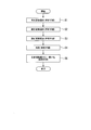
- FIG. 2 is a flowchart of the design process according to the embodiment.
- the objective function selection unit 11 selects at least one objective function from information stored in the storage unit 16 or inputted input information (objective function selection procedure, analysis procedure).
- Step S2 The design variable selection unit 12 selects at least one design variable from information stored in the storage unit 16 or input input information (design variable selection procedure, analysis procedure).
- Step S3 The design variable changing unit 13 sequentially changes the design variables selected by the design variable selecting unit 12 (design variable changing procedure, analysis procedure).
- Step S4 The analysis unit 14 performs analysis, for example, by the finite element method using the laminated shell element model (analysis procedure).
- Step S5 The objective function maximization / minimization unit 15 obtains an optimum point by searching for the maximum value or minimum value of the objective function selected by the objective function selection unit 11 in step S1 (maximization / minimization of objective function). Procedure, search procedure).
- FIG. 3 is a diagram illustrating a laminated shell element model for analysis using a discrete method according to the embodiment.
- the laminated shell element model 100 has an inner diameter of 14.1 [mm], a length of 300 [mm], and seven layers of fiber reinforced resin layers of the first layer Ly1 to the seventh layer Ly7.
- the lamination angle of each layer is 0 ° (degrees) (the direction along which the fibers extend in the longitudinal direction).
- a finite number of elements are connected by nodes to define a substantially rod-shaped model.
- Each element includes parameters such as element length, flexural modulus, Young's modulus E, and cross-sectional secondary moment I, for example.
- Table 1 shows an example of material information stored in the storage unit 16 or material information input to the design apparatus 1.
- the storage unit 16 stores information on prepregs A to I that are in the form of sheets in which fibers are impregnated with resin or the like.
- the storage unit 16 includes a prepreg ( ⁇ ) ( ⁇ is any one of A to I), a product number, fiber tensile elastic modulus [GPa], basis weight [g / m 2 ], resin content [% by mass], and thickness. [Mm] is stored in association with each other.
- the prepreg A has a product number of TR350C050S, a tensile modulus of fiber of 235 [GPa], a basis weight of 75 [g / m 2 ], a resin content of 25 [mass%], and a thickness of 0.062 [mm] is stored in association with each other.
- the basis weight is the weight per unit area.
- Table 1 except for the prepreg C, adjustments are made to be the same except for the elastic modulus of the yarn in consideration of later analysis.
- the example shown in Table 1 is an example, and the storage unit 16 may also store information on materials such as materials of other product numbers and thicknesses other than 0.062 [mm].
- the objective function selection unit 11 selects the bending rigidity of the golf shaft from the information stored in the storage unit 16 (step S1). Subsequently, the design variable selection unit 12 selects the type of prepreg from the information stored in the storage unit 16 (step S2). Subsequently, the design variable changing unit 13 changes the type of the stacking angle prepreg for each layer in order to stack a plurality of fiber reinforced resin layers (step S3).
- the analysis unit 14 performs analysis, for example, by a finite element method using the laminated shell element model (step S4).
- the objective function maximization / minimization unit 15 obtains the optimum point by searching for the maximum value of the stiffness, which is the objective function, in the result analyzed in step S4 (step S5). As a result, the material near the optimum point was prepreg I (Table 1).
- Example 2 will be described.
- a fiber reinforced resin layer is so brittle that rigidity is high. For this reason, it is necessary to consider not only the elastic modulus but also the strength. In particular, when only the 0 ° layer is used, the strength may be greatly reduced because crushing occurs in the circumferential direction. In this case, the strength can be increased by changing the stacking angle. Therefore, in the second embodiment, an example will be described in which a three-point bending strength is selected as an objective function and a stacking angle is selected as a design variable in order to consider such a strength problem.
- C as described in SG Standard CPSA 0098, Golf Club Shaft Certification Standard and Standard Confirmation Method (Product Safety Association of Japan, Minister of International Trade and Industry No. 5 No. 2087, October 4, 1993)
- the outline of “strength of mold shaft (1) three-point bending test” will be described.
- the C type means that the material of the shaft is made of non-metal such as fiber reinforced plastic.
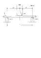
- FIG. 4 is a diagram showing a three-point bending test in SG standard CPSA 0098.
- the position T is a position of 90 [mm] from the tip.
- the position A is a position 175 [mm] from the tip.
- the position B is a position of 525 [mm] from the tip.
- the position C is a position 175 [mm] from the grip end.
- the symbol S is a shaft.
- “in the case of a C-shaped shaft, it should not be destroyed when a three-point bending test is performed” is a certification standard.
- FIG. 5 is a diagram illustrating a model based on the three-point bending test according to the example.
- the laminated shell element model 100 of the shaft has an inner diameter of 14.1 [mm], a length of 300 [mm], and seven layers of fiber reinforced resin layers composed of the first layer Ly1 to the seventh layer Ly7. It is a thing.
- the positions of the three points are 15 mm from one end, 150 [mm] at the center of both ends (one end and the other end), and 15 [mm] from the other end.
- the R at the position of 15 [mm] from each of the one end and the other end is 12.5 [mm]
- the indenter 201 at the position is 150 [mm] at the center of both ends (one end and the other end).
- R is 75 [mm].
- the center indenter 201 descends at a constant speed from above.
- the configuration of the design apparatus 1 is the same as that of the first embodiment.
- the design variable changing unit 13 sequentially changes the design variables selected by the design variable selecting unit 12.
- the design variable changing unit 13 performs sampling for discretely determining the design variable in the process of changing the design variable. The sampling performed by the design variable changing unit 13 will be described later.
- the objective function maximization / minimization unit 15 obtains an optimum point by searching for the maximum value or the minimum value of the objective function.
- the objective function maximization / minimization unit 15 approximates the objective function and creates a response surface in the process of searching for the maximum value or the minimum value of the objective function. The creation of the response surface performed by the objective function maximization / minimization unit 15 will be described later.
- FIG. 6 is a flowchart of design processing according to the embodiment.
- description is abbreviate
- the design variable changing unit 13 sequentially changes the design variables selected by the design variable selecting unit 12 (design variable changing procedure, analysis procedure).
- the design variable changing unit 13 performs sampling for discretely determining the design variable in step S31 (step S311, sampling procedure).
- Step S51 The objective function maximization / minimization unit 15 obtains an optimum point by searching for the maximum value or minimum value of the objective function (objective function maximization / minimization procedure, search procedure). In step S51, the objective function maximization / minimization unit 15 approximately calculates the objective function and creates a response surface (step S511, response surface creation procedure).
- FIG. 7 is a diagram illustrating a sampling procedure according to the embodiment.
- a case is considered in which the stacking angle of the two layers from the outside (sixth layer Ly6, seventh layer Ly7) is optimized.
- two adjacent layers for example, two layers from the outside are selected from the stack.
- the horizontal axis represents the stacking angle of the sixth layer
- the vertical axis represents the stacking angle of the seventh layer (outermost layer).
- the lamination angle A [° (degrees)] of the sixth layer and the lamination angle B [° (degrees)] of the seventh layer are represented by circles ( ⁇ 90, ⁇ 90), (-90, 90), (0, 0), (90, -90), and (90, 90) are sampling points. Since the strength analysis using the laminated shell is long in one analysis, it is practically important to reduce the number of analyzes as much as possible. For this reason, it is preferable that the sampling can cover the whole with as few sampling points as possible.
- the Space-Filling method is a method of filling the space in a well-balanced manner, and is composed of an algorithm that maximizes the “minimum value of the distance between each point”.
- the design variable changing unit 13 sets the sampled sampling points as the changed design variables.
- the design variable changing unit 13 may use a method other than the Space-Filling method as a sampling method.
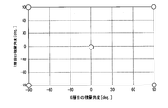
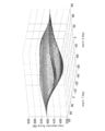
- FIG. 8 is a diagram illustrating an example of a response curved surface based on the three-point bending strength calculated using the sampling points of the sixth layer and the seventh layer according to the example.
- the first axis of the horizontal plane indicates the stacking angle (angle 6) of the sixth layer
- the second axis of the horizontal plane indicates the stacking angle (angle 7) of the seventh layer
- the vertical axis indicates the strength [N].
- the stacking angle is in the range of ⁇ 90 ° to + 90 °.
- the maximum value is obtained when the lamination angle of the sixth layer is ⁇ 90 ° and the lamination angle of the seventh layer is ⁇ 90 °, which indicates that the strength (rigidity) is the largest. .
- the objective function selection unit 11 selects the three-point bending strength from the information stored in the storage unit 16 (step S1). Subsequently, the design variable selection unit 12 selects a stacking angle from the information stored in the storage unit 16 (step S2). Subsequently, the design variable changing unit 13 samples the design variable (step S311). Subsequently, the design variable changing unit 13 sets the sampled points as the changed stacking angles of the two layers (sixth layer, seventh layer) from the outside, for example (step S31). Subsequently, the analysis unit 14 performs analysis, for example, by a finite element method using the laminated shell element (step S4).
- the objective function maximization / minimization unit 15 creates a response surface using the result analyzed in step S41 (step S511). Subsequently, the objective function maximization / minimization unit 15 searches for the maximum value of the objective function using the created response surface to obtain the optimum point (step S51).
- the lamination angle A [° (degrees)] of the sixth layer, which is the maximum value, and the lamination angle B [° (degrees)] of the sixth layer are ( ⁇ 90, -90), (-90, 90), (90, -90), (90, 90).
- the stacking angle of the tubular body ⁇ 90 ° and + 90 ° indicate the same stacking.
- strength (vertical axis) of four local maximum points must correspond.
- the strengths (vertical axes) of the four maximum points do not match. This is because, at the time of the sampling procedure, the periodicity that ⁇ 90 ° and + 90 ° are the same is not taken into consideration when a method that simply fills the space is used. In Example 3, an example in which such periodicity is considered will be described.
- One method that considers the periodicity is a method of periodically extending the sampling space infinitely. That is, in Example 2, the vicinity of ⁇ 90 ° and + 90 ° is sampled twice, which is equivalent to two points even though five points are sampled. Therefore, in this embodiment, double sampling is prevented by expanding the sampling space.
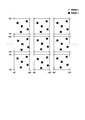
- FIG. 9 is a schematic diagram of sampling in the case of 5 points according to the embodiment.
- circles indicate sampling points selected by the sampling method in the second embodiment
- X marks indicate sampling points selected by the sampling method in the third embodiment.
- double sampling is prevented by expanding the sampling space.
- i represents the number of samples for each layer, and is a value of 2 to 50, for example. If the number is two or more, highly reliable results can be obtained. If it is 50 points or less, calculation time can be shortened. Further, j represents the total number of stacked layers, for example, not less than 1 and not more than 15, and 7 examples are described in the embodiment.
- L represents the distance between any two points among the plurality of sample points. F represents a function.
- the analysis part 14 calculates
- max (min (L)) means that the sampling points are distributed in a well-balanced manner by arranging the minimum L so as to be the maximum.
- the sampling points calculated in this way are shown in FIG. 7 or FIG. 7 and 9 show an example in which the number of sampling points is five, the number is not limited to this.
- the number of sampling points may be a predetermined value, or may be set or changed by the user of the design apparatus 1.
- the objective function maximization / minimization unit 15 creates a response surface using, for example, a radial basis function (RBF) using the calculated sampling points.
- the objective function maximization / minimization unit 15 may further ensure the periodicity by using Fourier series approximation in order to consider the periodicity in creating the response surface.
- the objective function maximization / minimization unit 15 performs Fourier series approximation using the following equation (2).
- FIG. 10 is a diagram illustrating a response surface obtained by performing first-order Fourier series approximation according to the embodiment.
- the example shown in FIG. 10 is an example in which two layers (sixth layer, seventh layer) are selected from the outside, as in the second embodiment.
- the first axis on the horizontal plane indicates the stacking angle (angle 6) of the sixth layer
- the second axis on the horizontal plane indicates the stacking angle (angle 7) of the seventh layer
- the vertical axis indicates the strength [N].
- first-order Fourier series approximation is performed in order to consider periodicity in creating a response surface.
- second-order Fourier series approximation is performed in the case of the first-order approximation.
- the whole may be smoothed and may not be found when a local optimum point exists. By changing this to a quadratic approximation, a local optimum point can also be found.
- FIG. 11 is a diagram illustrating a response surface obtained by performing a second-order Fourier series approximation according to the embodiment.
- the example shown in FIG. 11 is an example in which two layers (sixth layer, seventh layer) are selected from the outside, as in the second embodiment.
- the first axis of the horizontal plane indicates the stacking angle (angle 6) of the sixth layer
- the second axis of the horizontal plane indicates the stacking angle of the seventh layer (angle 7)
- the vertical axis indicates the strength [N]. Indicates the size.
- Equation (3) EI is the bending rigidity of the shaft, E is the Young's modulus, and I is the sectional moment of the shaft.
- GJ is the torsional rigidity of the shaft, G is the shear modulus, and J is the torsional constant (cross-sectional torsion moment).
- I is the order of the layers, the first layer is 1, and the seventh layer is 7.
- E (a i) xx is, E (a 1) xx is the Young's modulus of the innermost layer Ly1, E (a 2) xx is the Young's modulus of the layer Ly2 the second layer from the innermost, a ... To express.
- Ia i denotes the second moment of Ia 1 is the innermost layer LyI, second moment of layer Ly2 the second layer Ia 2 from innermost, a ....
- E (a i ) ss is E (a 1 ) ss is the shear elastic modulus of the innermost layer Ly1
- E (a 2 ) ss is the shear elastic modulus of the second layer Ly2 from the innermost side, and so on.
- Ja i represents torsional constant of Ja 1 is the innermost layer LyI
- torsional constant of the layer Ly2 the second layer Ja 2 from innermost a ....
- Each of f and g represents a function.
- ⁇ 1 represents the stacking angle of the first layer
- ⁇ 2 represents the stacking angle of the second layer
- ⁇ 7 represents the stacking angle of the seventh layer.
- EI was set to 35 [N ⁇ m2] or more, with the constraint that it has a hardness that can function as a shaft.
- GJ has a constraint that it is difficult to twist to the extent that it functions as a shaft, and is set to 12 [N ⁇ m2] or more.
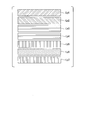
- FIG. 12 is a diagram illustrating an optimal configuration example at the position C when the constraint condition according to the embodiment is imposed.
- the stacking angle of the seventh layer Ly7 is 90 °
- the stacking angle of the sixth layer Ly6 is 15 ° (calculated 14.18 ° but 15 °).
- the stacking angle of the fifth layer Ly5 is 90 °
- the stacking angle of the fourth layer Ly4 is 0 °
- the stacking angle of the third layer Ly3 is 0 °
- the stacking angle of the second layer Ly1 is ⁇ 45 °
- the stacking angle is 45 °.
- the configuration shown in FIG. 12 is an example of a configuration having the maximum strength and the lightest weight.
- a constraint condition of the following expression (4) is imposed on the position B
- a constraint condition of the following expression (5) is imposed on the position A
- a constraint condition of the following expression (6) is imposed on the position T, so that the laminated structure is formed.
- Each value of the equations (4) to (6) has a constraint condition according to the size of the inner diameter having a hardness that allows EI to function as a shaft, and has a resistance to twisting that allows GJ to function as a shaft. This is a value set as a constraint condition according to the size of the inner diameter.
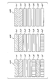
- FIG. 13 is a diagram illustrating an optimal configuration example at positions B, A, and T when the constraint condition according to the embodiment is imposed.
- the stacking angle of the seventh layer Ly7 is 90 °
- the stacking angle of the sixth layer Ly6 is 5 °
- the fifth layer from the outermost layer to the innermost layer.
- the stacking angle of Ly5 is 90 °
- the stacking angle of the fourth layer Ly4 is 0 °
- the stacking angle of the third layer Ly3 is 0 °
- the stacking angle of the second layer Ly1 is ⁇ 45 °
- the stacking angle of the first layer Ly1 is 45 °.
- the stacking angle of the seventh layer Ly7 is 90 °
- the stacking angle of the sixth layer Ly6 is 0 °
- the fifth layer from the outermost layer to the innermost layer.
- the stacking angle of Ly5 is 0 °
- the stacking angle of the fourth layer Ly4 is 0 °
- the stacking angle of the third layer Ly3 is 0 °
- the stacking angle of the second layer Ly1 is ⁇ 45 °
- the stacking angle of the first layer Ly1 is 45 °.
- the stacking angle of the seventh layer Ly7 is 0 °
- the stacking angle of the sixth layer Ly6 is 0 °
- the fifth layer from the outermost layer to the innermost layer.
- the stacking angle of Ly5 is 0 °
- the stacking angle of the fourth layer Ly4 is 0 °
- the stacking angle of the third layer Ly3 is 0 °
- the stacking angle of the second layer Ly1 is ⁇ 45 °
- the stacking angle of the first layer Ly1 is 45 °.
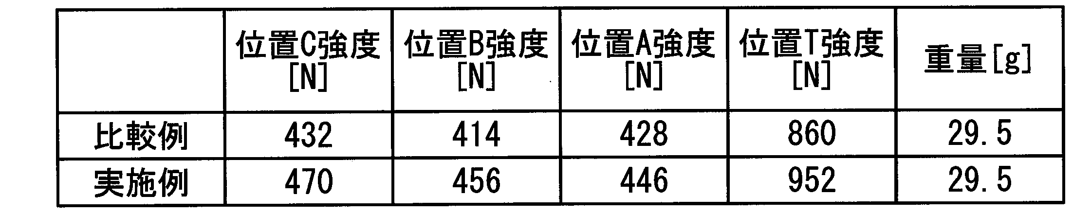
- Table 2 shows the results of the strength evaluation of the optimum lamination of the comparative example and the example at each position. Table 2 shows the results of actually creating what was obtained from the calculation and measuring the intensity at each position. Thus, according to the Example, it was confirmed that even if the weight is the same, the strength is increased compared to the comparative example.
- the second layer Ly6 from the outside at the position C and the position B is 15 ° and 5 °, respectively. If this design value is applied to a golf shaft, there is a possibility of violating the rules. This is because there is a rule that “effectively restricts the shaft from being designed to have asymmetric properties”, that is, “not intentionally left-right asymmetry” (eg, Rules Guide 2016 on Clubs and Balls (5th edition), Japan Golf Association). Therefore, it is desirable that the material is ⁇ 15 ° and ⁇ 5 ° using prepreg C (Table 1) having a thickness of about half. In addition, the shaft weight of the comparative example and the optimum lamination was the same, and the rigidity of the comparative example was higher.
- the rigidity was evaluated by a cantilever bending test using a 1 [kg] weight.
- the golf shaft cantilever bending test conforms to, for example, the above-mentioned SG standard CPSA 0098, and details thereof are omitted.
- FIG. 14 is a diagram showing a configuration example of the optimum lamination of the golf shaft with the maximum strength.
- the golf shaft in the present embodiment is obtained by winding each prepreg around a mandrel called a mandrel, drawing out the mandrel after heat curing, and polishing the outer layer. This is the same as a general golf shaft manufacturing method.
- the polishing margin is not shown.
- the outer diameter adjustment layer exists on the tip portion (position T side), but is not illustrated.
- the position C side is a butt portion.
- the material used for each layer was all prepreg E (Table 1).
- the stacking angles of the positions C, B, A and T of the angle layer 31 which is the innermost layer are + 45 °.
- the angle layer 32 has a stacking angle of ⁇ 45 ° at each of the positions C, B, A, and T, and is configured to be stacked on the angle layer 31.
- the straight layer 33 has a stacking angle of 0 ° at each of the positions C, B, A, and T, and is configured to be stacked on the angle layer 32.
- the straight layer 34 has a stacking angle of 0 ° at each of the positions C, B, A, and T, and is configured to be stacked on the straight layer 33.
- the change layer 35 c has a stacking angle of + 90 ° and is stacked at the position C of the straight layer 34.
- the change layer 36c has a stacking angle of + 15 ° and is configured to be stacked on the change layer 35c.
- the change layer 37c has a stacking angle of + 90 ° and is configured to be stacked on the change layer 36c.
- the change layer 35 b has a stacking angle of + 90 ° and is stacked at the position B of the straight layer 34.
- the change layer 36b has a stacking angle of 5 ° and is configured to be stacked on the change layer 35b.
- the change layer 37b has a stacking angle of + 90 ° and is configured to be stacked on the change layer 36b.
- the change layer 35 a has a stacking angle of 0 °, and is stacked at the position A of the straight layer 34.
- the change layer 36a has a stacking angle of 0 ° and is configured to be stacked on the change layer 35a.
- the change layer 37a has a stacking angle of + 90 ° and is configured to be stacked on the change layer 36a.
- the change layer 35t has a stacking angle of 0 ° and is stacked at the position A of the straight layer 34.
- the change layer 36t has a stacking angle of 0 ° and is configured to be stacked on the change layer 35t.
- the change layer 37t has a stacking angle of 0 ° and is configured to be stacked on the change layer 36t.
- Each layer may be configured by wrapping around another adjacent layer.
- each end is abutted, that is, without being overlapped and arranged without a gap, but each may be wound alone.
- the diagonally abutted portions represented by the change layers 35c and 35b in FIG. 14 are relief portions for avoiding stress concentration.
- Each of the change layer 35c, the change layer 36c, and the change layer 37c is disposed from 0 to 325 mm (hereinafter referred to as the vicinity of the position C) starting from the butt end.
- the standard of the length is up to the center of the relief portion.
- Each of the change layer 35b, the change layer 36b, and the change layer 37b is 325 to 625 mm (hereinafter referred to as the vicinity of the position B).
- each of the change layer 35a, the change layer 36a, and the change layer 37a is disposed at 625 to 975 mm (hereinafter referred to as the vicinity of the position A).
- Each of the change layer 35t, the change layer 36t, and the change layer 37t is disposed up to the end of 975-chip (hereinafter referred to as the vicinity of the position T).
- the vertical stacking component decreases sequentially.
- the vertical stacking component was defined as the sum of the stacking angles of the respective layers except for the two innermost angle layers.
- the angle layer refers to a layer in which the fiber orientation with respect to the longitudinal direction of the shaft is + 20 ° to + 75 ° and ⁇ 20 ° to ⁇ 75 °.
- the vertical lamination component is an absolute value and is a dimensionless amount.
- the value obtained by dividing the vertical stacking component of each layer in each region is divided by the number of prepregs in each layer. Then, the obtained vertical stacking component of each layer is added over all layers. For example, when comparing the 0 ° layer and the 15 ° layer, the vertical stacking component is 0 for the 0 ° layer and 15 for the 15 ° layer, so that the 15 ° layer has a larger vertical stacking component.
- At least one layer is composed of a plurality of prepregs having different lamination angles.
- the layer composed of a plurality of prepregs may be a layer extending over the entire length or a partially disposed layer.
- the laminated structure In the vicinity of position C, the laminated structure is + 45 °, ⁇ 45 °, 0 °, 0 °, 90 °, 15 ° to 45 °, and 90 ° in order from the inside.
- the vertical lamination component is 195 to 225. Since the vicinity of the position C has high rigidity, it is crushed and destroyed while there is little bending due to bending. That is, the crushing rigidity becomes dominant. If the vertical lamination component, which is a pseudo and relatively numerical value of the crushing rigidity, is 195 or more, it is preferable because crushing rigidity increases. If the vertical lamination component is 225 or less, the bending rigidity is sufficient, which is preferable.
- the laminated structure In the vicinity of position B, the laminated structure is + 45 °, ⁇ 45 °, 0 °, 0 °, 90 °, 5 ° to 15 °, and 90 ° in order from the inside.
- the vertical stack component is 185 to 195, which is smaller than the vertical stack component at position C. Since the vicinity of the position B is thinner and softer than the vicinity of the position C, the bending component becomes larger than the vicinity of the position C at the time of breakage. By setting the vertical lamination component in the above range smaller than the vertical lamination component in the vicinity of the position C, the bending rigidity can be increased.
- the laminated structure In the vicinity of position A, the laminated structure is + 45 °, ⁇ 45 °, 0 °, 0 °, 0 °, and 90 ° in order from the inside.
- the vertical stack component is 90. It is smaller than the vertical stacking component at position B. If the vertical lamination component at the position A is too large, the rigidity is likely to be insufficient. Therefore, the vertical lamination component is preferably less than 180. Since the vicinity of the position A is thinner and softer than the vicinity of the position B, the bending component is larger than the vicinity of the position B at the time of breakage. Therefore, in order to increase the bending rigidity, it is preferable that the vertical lamination component is in the above range smaller than the vertical lamination component in the vicinity of the position B.
- the laminated structure In the vicinity of the position T, the laminated structure is + 45 °, ⁇ 45 °, 0 °, 0 °, 0 °, and 0 ° in order from the inside.
- the vertical stack component is zero.
- the fracture In the vicinity of the position T, the fracture is almost caused by bending, so that the vertical lamination component is preferably zero.
- the above-described characteristics depend on the fact that bending deformation does not occur much at the time of performing the three-point bending, and it is crushed and easily broken. That is, the cylindrical shaft is deformed into an ellipse and broken. Therefore, the conclusion is reached that a large number of 90 ° layers for increasing the crushing rigidity should be arranged.
- bending rigidity is low on the chip side, and large bending deformation occurs when performing three-point bending, and crushing deformation hardly occurs. Therefore, the conclusion is reached that many 0 ° layers for increasing the bending rigidity should be arranged.
- the shaft having the above-described configuration (FIG. 14) was obtained by the design method of the present embodiment.
- the number of layers is 7 and the prepreg E is used.
- the shaft designed by the design apparatus 1 was approximately 30 [g] or less (actual measurement was 29.5 [g]).
- the rigidity was designed to be 90 [mm] or more in a cantilever bending test using a 1 [kg] weight. The measured value of the cantilever bending test was 91 [mm].
- a design variable for example, material
- an objective function for example, rigidity
- a design variable for example, a stacking angle
- an objective function for example, three-point bending strength
- the whole can be covered with as few sampling points as possible, the whole can be covered with as few sampling points as possible, and the analysis time can be shortened.
- the sampling space is expanded in the sampling procedure by Fourier series approximation, so that double sampling can be prevented.
- the Fourier series approximation is first order in the sampling procedure, the entire solution space can be known, and the optimum stacking configuration for maximizing the intensity (here, the design variable is the stacking angle) The stacking angle of each layer) can be known.
- the Fourier series approximation is quadratic, a local optimum point can also be found.
- At least one layer of the stack includes a plurality of regions (for example, the vicinity of position C, the vicinity of position B, the vicinity of position A, and the vicinity of position T).
- a design variable that maximizes or minimizes the objective function can be obtained.
Landscapes
- Engineering & Computer Science (AREA)
- Physics & Mathematics (AREA)
- Theoretical Computer Science (AREA)
- Mechanical Engineering (AREA)
- Composite Materials (AREA)
- Chemical & Material Sciences (AREA)
- General Physics & Mathematics (AREA)
- Geometry (AREA)
- Computer Hardware Design (AREA)
- General Engineering & Computer Science (AREA)
- Evolutionary Computation (AREA)
- Health & Medical Sciences (AREA)
- General Health & Medical Sciences (AREA)
- Physical Education & Sports Medicine (AREA)
- Computational Mathematics (AREA)
- Mathematical Analysis (AREA)
- Mathematical Optimization (AREA)
- Pure & Applied Mathematics (AREA)
- Golf Clubs (AREA)
- Architecture (AREA)
- Software Systems (AREA)
Abstract
Description
本願は、2016年5月13日に出願された日本国特願2016-097268号に基づき優先権を主張し、その内容をここに援用する。
例えば、特許文献1に記載の技術分野はゴルフシャフトの設計方法及び製造方法に関するもので、シャフトの設計用パラメータを関数表現して離散的手法を用いた解析と最適化計算を行うものである。また、特許文献2に記載の技術もゴルフシャフトに関するものであり、用具によるスイング動作の変化に着目し、シャフトの性能を最適化したものである。
[2]上記[1]の態様において、前記目的関数は、複数の変数からなってもよい。
[3]上記[1]または[2]の態様において、前記離散的手法は、有限要素法、境界要素法、個別要素法、Element Free Galerkin(EFG)法、eXtended FEM(XFEM)法、Smoothed Particle Hydrodynamics(SPH)法、Capsular Particle Methodのうち少なくとも1つであり、前記目的関数は、前記管状体の強度、重量、曲げ剛性、捩り剛性のうちいずれか1つ又は複数の線形結合で表されたものであり、前記探索手順は、前記管状体の、積層された各層の積層角度、材料定数、パイプ形状のうち少なくとも1つを前記設計変数として選択してもよい。
[4]上記[1]から[3]のいずれか1つの態様において、前記管状体の積層される複数の層のうち少なくとも1つの層は、2つ以上の領域を備え、前記解析手順は、前記層の領域毎に前記複数の目的関数を算出し、前記探索手順は、前記層の領域毎に前記設計変数の値を探索してもよい。
[5]上記[1]から[4]のいずれか1つの態様において、前記解析手順が、更に、前記設計変数である前記層の積層角度を離散的に選択するサンプリング手順、を含み、前記解析手順は、前記サンプリング手順によって選択した、前記層の積層角度を、前記順次変化させた前記設計変数として、前記複数の目的関数を算出し、前記探索手順は、前記解析手順によって算出した前記複数の目的関数に近似するよう算出した応答曲面を作成する応答曲面作成手順、を含み、前記探索手順は、前記応答曲面作成手順によって作成した前記応答曲面中で前記目的関数が最大値又は最小値をとるような前記設計変数の値を探索してもよい。
[6]上記[5]の態様において、前記サンプリング手順は、サンプリング空間を繰り返しのある無限空間に拡張し、各サンプリング点同士の距離の最小値を最大化するサンプリングを行ってもよい。
[7]上記[5]または[6]の態様において、前記応答曲面作成手順は、フーリエ級数近似にて応答曲面の作成を行ってもよい。
[8]上記[7]の態様において、前記フーリエ級数近似は、一次近似又は二次近似であってもよい。
[11]上記[10]の態様において、少なくとも1層が積層角度を変えた複数のプリプレグからなってもよい。
[12]上記[10]または[11]の態様において、バット端部を基準とし、0mm以上かつ325mm未満を位置C近傍、325mm以上かつ625mm未満を位置B近傍、625mm以上~975mmを位置A近傍、975mm以上かつチップ端までを位置T近傍と定義したとき、1)~4)を満たしてもよい。
1)位置C近傍での垂直積層成分が、195以上、225未満である
2)位置B近傍での垂直積層成分が、185以上であり、C点の垂直積層成分よりも小さい
3)位置A近傍での垂直積層成分が、90以上、180未満である
4)位置T近傍での垂直積層成分が、0である
[13]上記[10]から[12]のいずれか1つの態様において、位置C近傍での積層角度が前記管状体の内側から順に、+45°、-45°、0°、0°、90°、15°~45°、90°であり、位置B近傍での積層角度が前記管状体の内側から順に、+45°、-45°、0°、0°、90°、5°~15°、90°であり、位置A近傍での積層角度が前記管状体の内側から順に、+45°、-45°、0°、0°、0°、0°、90°であり、位置T近傍での積層角度が前記管状体の内側から順に、+45°、-45°、0°、0°、0°、0°、0°であってもよい。
[14]上記[10]または[11]の態様において、位置C近傍での積層角度が前記管状体の内側から順に、+45°、-45°、0°、0°、90°、+15°~45°、-15°~-45°、90°であり、位置B近傍での積層角度が前記管状体の内側から順に、+45°、-45°、0°、0°、90°、-5°~-15°、+5°~+15°、90°であり、位置A近傍での積層角度が前記管状体の内側から順に、+45°、-45°、0°、0°、0°、0°、90°であり、位置T近傍での積層角度が前記管状体の内側から順に、+45°、-45°、0°、0°、0°、0°、0°であってもよい。
なお、本実施形態では、複数の層(例えば繊維強化樹脂層)からなる管状体の例として、ゴルフシャフトを例に説明するが、これに限られない。本実施形態は、釣竿、自転車のフレーム、テニスラケット等のスポーツ用途部材、さらにはロボットアームやカーボンロール、ドライブシャフト等の産業用途部材の複数の繊維強化樹脂層からなる管状体に適用することができる。
図1は、実施形態に係る設計装置1のブロック図である。図1に示すように、設計装置1は、目的関数選択部11、設計変数選択部12、設計変数変更部13、解析部14、目的関数最大化・最小化部15、および記憶部16を備える。
なお、設計装置1の一部または全ては、パーソナルコンピュータおよびパーソナルコンピュータにインストールされているソフトウェアによって実現するようにしてもよい。
離散的手法は、有限要素法、境界要素法、個別要素法、Element Free Galerkin(EFG)法、eXtended FEM(XFEM)法、Smoothed Particle Hydrodynamics(SPH)法、Capsular Particle Method(CPM)のうち少なくとも1つである。一般的に普及しており、信頼性が高いため、好ましくは有限要素法が良い。解析部14は、例えば構造解析ソフトウェアを用いて解析を行う。構造解析ソフトウェアは、例えばLivermore Software Technology Corporation社のLS-DYNA(登録商標)である。例えば、解析部14は、LS-DYNA(登録商標)の解法設定において、時間発展を動的陽解法に設定し、解析ソルバーを非線形行動解析に設定し、離散的手法を有限要素法に設定する。また、解析部14は、LS-DYNA(登録商標)の要素設定において、要素形態を肉厚シェル要素に設定し、要素定式化を2次元平面応力要素に設定し、アワグラスコントロールを粘性型に設定する。なお、上述した例は一例であり、解析部14は、他の設定を用いてもよい。なお、積層シェル要素モデルについては、後述する。
図2は、実施例に係る設計処理のフローチャートである。
(ステップS1)目的関数選択部11は、記憶部16が記憶する情報、または入力された入力情報から少なくとも1つの目的関数を選択する(目的関数選択手順、解析手順)。
(ステップS3)設計変数変更部13は、設計変数選択部12が選択した設計変数を順次変更する(設計変数変更手順、解析手順)。
(ステップS5)目的関数最大化・最小化部15は、ステップS1で目的関数選択部11が選択した目的関数の最大値又は最小値を探索することで最適点を求める(目的関数最大化・最小化手順、探索手順)。
図3は、実施例に係る離散的手法を用いた解析のための積層シェル要素モデルを示す図である。なお、図3に示す図では、半断面図で示している。
図3に示すように、積層シェル要素モデル100は、内径が14.1[mm]、長さが300[mm]、繊維強化樹脂層を第1層Ly1~第7層Ly7による7層積層し、各層の積層角度が0°(度)(長手方向に繊維が沿う方向)である。
また、積層シェル要素モデルでは、有限個の要素を節点で接続することにより、略棒状のモデルとして定義する。また、各要素それぞれには、例えば、要素の長さ、曲げ弾性率、ヤング率E、断面二次モーメントI等のパラメータが含まれる。
表1は、記憶部16が記憶する材料の情報、または設計装置1に入力される材料の情報の一例を示す。

なお、表1に示した例は一例であり、記憶部16は、他の品番の材料、0.062[mm]以外の厚さ等の材料の情報も記憶していてもよい。
目的関数選択部11は、記憶部16が記憶する情報から、ゴルフシャフトの曲げ剛性を選択する(ステップS1)。続けて、設計変数選択部12は、記憶部16が記憶する情報から、プリプレグの種類を選択する(ステップS2)。続けて、設計変数変更部13は繊維強化樹脂層を複数層積層するため各層ごとに積層角度プリプレグの種類を変更する(ステップS3)。解析部14は、積層シェル要素モデルを用いて、例えば有限要素法によって解析を行う(ステップS4)。目的関数最大化・最小化部15は、ステップS4で解析した結果において、目的関数である剛性の最大値を探索することで最適点を求める(ステップS5)。
この結果、最適点に近い材料としては、プリプレグI(表1)であった。
一般に、繊維強化樹脂層は、剛性が高いほど脆い。このため、弾性率だけでなく強度も考慮する必要がある。特に、0°層のみで構成した場合、周方向に潰れが発生するため強度が大きく低下する場合がある。この場合は、積層角度を変更することで強度を高めることができる。このため、実施例2では、このような強度問題を考慮するため目的関数として3点曲げ強度を選択し、設計変数として積層角度を選択する例を説明する。
SG基準 CPSA 0098によれば、「C型シャフトにあたっては、3点曲げ試験を行ったときに破壊しないこと」が認定基準となっている。
図5は、実施例に係る3点曲げ試験に基づくモデルを示す図である。図5に示すようにシャフトの積層シェル要素モデル100は、内径が14.1[mm]、長さが300[mm]、繊維強化樹脂層を第1層Ly1~第7層Ly7による7層積層したものである。
3点の位置は、図5に示すように、一端から15mmの位置、両端(一端と他端)の中心の150[mm]に位置、他端から15[mm]の位置である。SG基準 CPSA 0098に従って、一端および他端それぞれから15[mm]の位置のRが12.5[mm]であり、両端(一端と他端)の中心の150[mm]に位置における圧子201のRが75[mm]である。このモデルでは、中央の圧子201が、上から一定の速度で降りてくるものである。
設計変数変更部13は、設計変数選択部12が選択した設計変数を順次変更する。設計変数変更部13は、設計変数を変更する処理において、設計変数を離散的に決めるサンプリングを行う。なお、設計変数変更部13が行うサンプリングについては、後述する。
目的関数最大化・最小化部15は、目的関数の最大値又は最小値を探索することで最適点を求める。目的関数最大化・最小化部15は、目的関数の最大値又は最小値を探索する処理において、目的関数を近似的に算出して応答曲面を作成する。なお、目的関数最大化・最小化部15が行う応答曲面の作成については、後述する。
図6は、実施例に係る設計処理のフローチャートである。なお、実施例1と同じ処理については、同じ符号を用いて説明を省略する。
(ステップS31)設計変数変更部13は、設計変数選択部12が選択した設計変数を順次変更する(設計変数変更手順、解析手順)。なお、設計変数変更部13は、ステップS31において、設計変数を離散的に決めるサンプリングを行う(ステップS311、サンプリング手順)。
図7は、実施例に係るサンプリング手順を示す図である。なお、図7では、説明を単純化するために、外側から2層(6層目Ly6、7層目Ly7)の積層角度を最適化する場合を考える。このように、本実施例では、積層のうち、隣接する2つの層(例えば、外側から2層)を選択する。
ここで、Space-Filling法とは、空間をバランスよく埋める手法であり、「各点の距離の最小値」を最大化するアルゴリズムで構成される。設計変数変更部13は、このように、サンプリングしたサンプリング点を変更した設計変数とする。なお、設計変数変更部13は、サンプリングの手法としてSpace-Filling法以外の手法を用いてもよい。
図8は、実施例に係る6層目と7層目のサンプリング点を用いて算出した3点曲げ強度に基づく応答曲面の一例を示す図である。
図8において、水平面の第1の軸が第6層の積層角度(angle6)を示し、水平面の第2の軸が第7層の積層角度(angle7)を示し、縦軸が強度[N]の大きさを示す。なお、積層角度は、-90°~+90°の範囲とする。
図8に示す例では、6層目の積層角度を-90°、7層目の積層角度を-90°にしたときが最大値であり、強度(剛性)が最も大きくなることを示している。
目的関数選択部11は、記憶部16が記憶する情報から、3点曲げ強度を選択する(ステップS1)。続けて、設計変数選択部12は、記憶部16が記憶する情報から、積層角度を選択する(ステップS2)。続けて、設計変数変更部13は、設計変数に対してサンプリングを行う(ステップS311)。続けて、設計変数変更部13は、サンプリングした点を、例えば外側から2層(6層目、7層目)それぞれの変更した積層角度とする(ステップS31)。続けて、解析部14は、積層シェル要素を用いて、例えば有限要素法によって解析を行う(ステップS4)。続けて、目的関数最大化・最小化部15は、ステップS41で解析した結果を用いて応答曲面を作成する(ステップS511)。続けて、目的関数最大化・最小化部15は、作成した応答曲面を用いて、目的関数の最大値を探索することで最適点を求める(ステップS51)。
この理由は、サンプリング手順の時点で、単純に空間を埋めるような手法を用いた場合に-90°と+90°が同一であるという周期性が考慮されていないためである。実施例3では、このような周期性を考慮した例を説明する。
すなわち、実施例2では、-90°と+90°付近が2重にサンプリングされていることになり、5点サンプリングしているにもかかわらず、2点分と同等である。そこで、本実施例では、サンプリング空間を拡張することで、2重サンプリングを防ぐ。
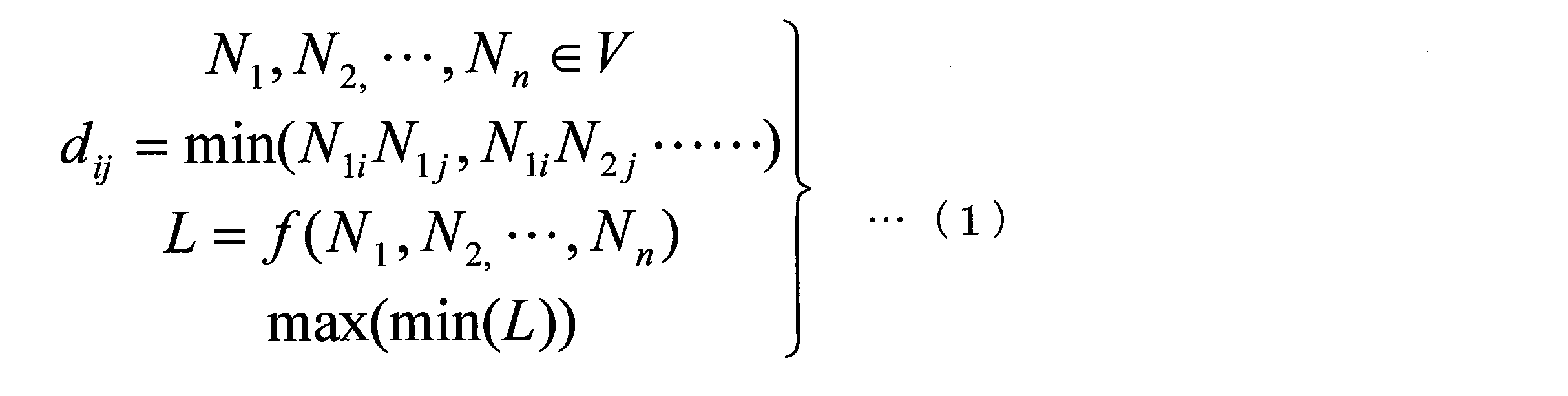
解析部14は、式(1)において、max(min(L))によって新たなサンプル点を求める。max(min(L))の意味合いは、最小のLが最大になるように配置することで、空間全体にバランスよくサンプリング点をばらまくことを意味している。
このように算出されたサンプリング点は、図7または図9である。なお、図7および図9では、サンプリング点の数が5つの例を示したが、数はこれに限られない。サンプリング点の数は、所定の値であってもよく、設計装置1の利用者が設定または変更するようにしてもよい。

図10は、実施例に係る1次のフーリエ級数近似を行った応答曲面を示す図である。なお、図10に示す例は、実施例2と同様に、外側から2層(6層目、7層目)を選択した例である。図10において、水平面の第1の軸が第6層の積層角度(angle6)を示し、水平面の第2の軸が第7層の積層角度(angle7)を示し、縦軸が強度[N]の大きさを示す。
図10に示す応答曲面により、解空間全体を知ることができ、強度を最大化するための最適な積層構成(ここでは設計変数を積層角度としたため各層の積層角度)を知ることができる。
1次近似の場合、全体が平滑化されてしまい局所的な最適点が存在する場合に見つけ出すことができない可能性がある。これを2次近似に変更することで局所的な最適点も見つけることができる。
実施例4では、前述した位置Cに対して、次式(3)の制約条件を用いる。

なお、EIはシャフトとして機能する程度の硬さを有することを制約条件とし、35[N・m2]以上とした。GJはシャフトとして機能する程度の捩れにくさを有することを制約条件とし、12[N・m2]以上とした。
図12は、実施例に係る制約条件を課したときの位置Cにおける最適構成例を示す図である。
図12に示すように、最外層から最内層の順に、7層目Ly7の積層角度が90°、6層目Ly6の積層角度が15°(計算上は14.18°だが15°とした)、5層目Ly5の積層角度が90°、4層目Ly4の積層角度が0°、3層目Ly3の積層角度が0°、2層目Ly1の積層角度が-45°、1層目Ly1の積層角度が45°である。
なお、図12に示した構成は、強度が最大であり、重量が最も軽い構成の例である。

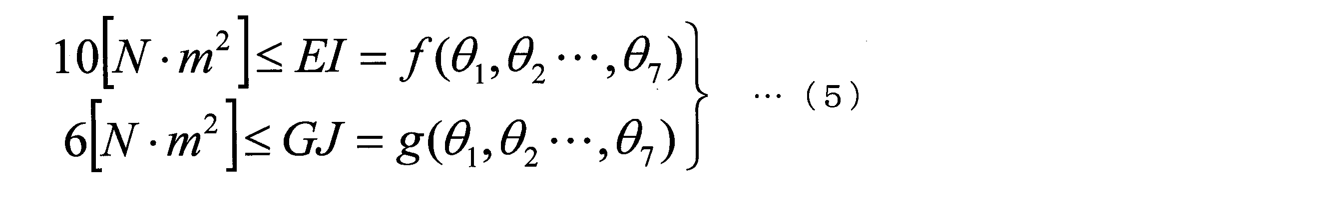

図13は、実施例に係る制約条件を課したときの位置B、A、Tにおける最適構成例を示す図である。
図13の符号g101が示す領域に示すように、位置Bでは、最外層から最内層の順に、7層目Ly7の積層角度が90°、6層目Ly6の積層角度が5°、5層目Ly5の積層角度が90°、4層目Ly4の積層角度が0°、3層目Ly3の積層角度が0°、2層目Ly1の積層角度が-45°、1層目Ly1の積層角度が45°である。
剛性評価は1[kg]の錘を用いた片持ち曲げ試験にて行った。ゴルフシャフトの片持ち曲げ試験は、例えば前述したSG基準 CPSA 0098に従うものであり、詳細は省略する。
ここで、強度を最大化したゴルフシャフトの最適積層の例について説明する。設計条件は、位置Cの内径が14.1[mm]、位置Bの内径が13.0[mm]、位置Aの内径が9.8[mm]、位置Tの内径が8.4[mm]である。
図14は、強度を最大化したゴルフシャフトの最適積層の構成例を示す図である。
アングル層32は、位置C、B、AおよびTそれぞれの積層角度が-45°であり、アングル層31に積層して構成される。
ストレート層34は、位置C、B、AおよびTそれぞれの積層角度が0°であり、ストレート層33に積層して構成される。
変化層36cは、積層角度が+15°であり、変化層35cに積層して構成される。
変化層37cは、積層角度が+90°であり、変化層36cに積層して構成される。
変化層36bは、積層角度が5°であり、変化層35bに積層して構成される。
変化層37bは、積層角度が+90°であり、変化層36bに積層して構成される。
変化層36aは、積層角度が0°であり、変化層35aに積層して構成される。
変化層37aは、積層角度が+90°であり、変化層36aに積層して構成される。
変化層36tは、積層角度が0°であり、変化層35tに積層して構成される。
変化層37tは、積層角度が0°であり、変化層36tに積層して構成される。
なお、変化層35c,変化層35b,変化層35a,変化層35t、変化層36c,変化層36b,変化層36a,変化層36t、変化層37c,変化層37b,変化層37a,変化層37tそれぞれは、各端部が突き合わされるように、すなわち重ね合わせることなく且つ隙間なく配置されるように形成されることが望ましいが、それぞれが単体で巻き付けられてもよい。ここで、図14の変化層35c、35bに代表される斜めに突き合わされている部分は応力集中を避けるための逃がし部である。なお、突き合わせた部位に関しては、重ならない限り、例えば、製造上不可避な程度の間隔を有して配置されていてもよい。
I.バット側からチップ側に向かうに従って、順次垂直積層成分が小さくなる。
ここで垂直積層成分とは、最内層のアングル層の2層を除いた各層の積層角度の和と定義した。なお、アングル層とは、シャフト長手方向に対する繊維の配向が+20°~+75°、-20°~-75°である層を指す。また、垂直積層成分は絶対値であり、無次元量とした。
位置C近傍、位置B近傍、位置A近傍、位置T近傍の垂直積層成分を算出する場合は、それぞれの領域において、各層の垂直積層成分を加算した値を各層のプリプレグの枚数で除算してから、求めた各層の垂直積層成分を全層に亘って加算して求める。例えば、0°層と15°層を比較した場合、垂直積層成分は、0°層では0であり、15°層では15になるため、垂直積層成分は15°層の方が大きい。また、位置C近傍の積層数が3層であり、第一の層が90°層の1枚であり、第二の層が45°と15°の2枚を突き合わせており、第三の層が90°を2枚突き合わせている場合、垂直積層成分は90/1+(45+15)/2+(90+90)/2=210となる。
II.少なくとも1層が積層角度を変えた複数のプリプレグからなる。複数のプリプレグからなる層は、全長に亘る層であってもよく、部分的に配置された層でもよい。
一方、チップ側は曲げ剛性が低く、3点曲げ実施時には曲げ変形が大きく生じ、潰し変形はあまり生じない。よって、曲げ剛性を高めるための0°層を多く配置すべきという結論に達する。
また、実施形態によれば、設計したい目的関数(例えば3点曲げ強度)が最大又は最小となる設計変数(例えば積層角度)を層毎に求めることができる。
また、実施形態によれば、フーリエ級数近似によるサンプリング手順において、サンプリング空間を拡張したので、2重サンプリングを防ぐことができる。
また、実施形態によれば、サンプリング手順において、フーリエ級数近似が一次の場合、解空間全体を知ることができ、強度を最大化するための最適な積層構成(ここでは設計変数を積層角度としたため各層の積層角度)を知ることができる。また、フーリエ級数近似が二次の場合、局所的な最適点も見つけることができる。
Claims (14)
- 複数の繊維強化樹脂層を積層してなる管状体の設計変数の値を順次変化させながら、積層モデルを用いた離散的手法によって繰り返し計算を行って、前記管状体の複数の目的関数を算出する解析手順と、
算出された前記複数の目的関数の中から最大値又は最小値となる前記設計変数の値を探索する探索手順と、
を含む管状体設計方法。 - 前記目的関数は、複数の変数からなる
請求項1に記載の管状体設計方法。 - 前記離散的手法は、有限要素法、境界要素法、個別要素法、Element Free Galerkin(EFG)法、eXtended FEM(XFEM)法、Smoothed Particle Hydrodynamics(SPH)法、Capsular Particle Methodのうち少なくとも1つであり、
前記目的関数は、前記管状体の強度、重量、曲げ剛性、捩り剛性のうちいずれか1つ又は複数の線形結合で表されたものであり、
前記探索手順は、前記管状体の、積層された各層の積層角度、材料定数、パイプ形状のうち少なくとも1つを前記設計変数として選択する、
請求項1または請求項2に記載の管状体設計方法。 - 前記管状体の積層される複数の層のうち少なくとも1つの層は、2つ以上の領域を備え、
前記解析手順は、前記層の領域毎に前記複数の目的関数を算出し、
前記探索手順は、前記層の領域毎に前記設計変数の値を探索する、
請求項1から請求項3のいずれか1項に記載の管状体設計方法。 - 前記解析手順が、更に、前記設計変数である前記層の積層角度を離散的に選択するサンプリング手順、を含み、
前記解析手順は、前記サンプリング手順によって選択した、前記層の積層角度を、前記順次変化させた前記設計変数として、前記複数の目的関数を算出し、
前記探索手順は、前記解析手順によって算出した前記複数の目的関数に近似するよう算出した応答曲面を作成する応答曲面作成手順、を含み、
前記探索手順は、前記応答曲面作成手順によって作成した前記応答曲面中で前記目的関数が最大値又は最小値をとるような前記設計変数の値を探索する、
請求項1から請求項4のいずれか1項に記載の管状体設計方法。 - 前記サンプリング手順は、サンプリング空間を繰り返しのある無限空間に拡張し、各サンプリング点同士の距離の最小値を最大化するサンプリングを行う、
請求項5に記載の管状体設計方法。 - 前記応答曲面作成手順は、フーリエ級数近似にて応答曲面の作成を行う、
請求項5または請求項6に記載の管状体設計方法。 - 前記フーリエ級数近似は、一次近似又は二次近似である、
請求項7に記載の管状体設計方法。 - 前記管状体は、ゴルフシャフトであり、
請求項1から請求項8のいずれか1項に記載の管状体設計方法によってゴルフシャフトを設計する、ゴルフシャフト設計方法。 - 最内層のアングル層2層を除いた各層の積層角度の和である垂直積層成分が、バット側からチップ側に向かうにしたがって小さくなるゴルフシャフト。
- 少なくとも1層が積層角度を変えた複数のプリプレグからなる
請求項10に記載のゴルフシャフト。 - バット端部を基準とし、0mm以上かつ325mm未満を位置C近傍、325mm以上かつ625mm未満を位置B近傍、625mm以上~975mmを位置A近傍、975mm以上かつチップ端までを位置T近傍と定義したとき、1)~4)を満たす、
請求項10または請求項11に記載のゴルフシャフト。
1)位置C近傍での垂直積層成分が、195以上、225未満である
2)位置B近傍での垂直積層成分が、185以上であり、C点の垂直積層成分よりも小さい
3)位置A近傍での垂直積層成分が、90以上、180未満である
4)位置T近傍での垂直積層成分が、0である - 位置C近傍での積層角度が前記管状体の内側から順に、+45°、-45°、0°、0°、90°、15°~45°、90°であり、位置B近傍での積層角度が前記管状体の内側から順に、+45°、-45°、0°、0°、90°、5°~15°、90°であり、位置A近傍での積層角度が前記管状体の内側から順に、+45°、-45°、0°、0°、0°、0°、90°であり、位置T近傍での積層角度が前記管状体の内側から順に、+45°、-45°、0°、0°、0°、0°、0°である、
請求項10から12のいずれか1項に記載のゴルフシャフト。 - 位置C近傍での積層角度が前記管状体の内側から順に、+45°、-45°、0°、0°、90°、+15°~45°、-15°~-45°、90°であり、位置B近傍での積層角度が前記管状体の内側から順に、+45°、-45°、0°、0°、90°、-5°~-15°、+5°~+15°、90°であり、位置A近傍での積層角度が前記管状体の内側から順に、+45°、-45°、0°、0°、0°、0°、90°であり、位置T近傍での積層角度が前記管状体の内側から順に、+45°、-45°、0°、0°、0°、0°、0°である、
請求項10または請求項11に記載のゴルフシャフト。
Priority Applications (5)
| Application Number | Priority Date | Filing Date | Title |
|---|---|---|---|
| KR1020187032294A KR20180135917A (ko) | 2016-05-13 | 2017-05-12 | 관상체 설계 방법, 골프 샤프트 설계 방법 및 골프 샤프트 |
| CN201780029021.8A CN109153193A (zh) | 2016-05-13 | 2017-05-12 | 管状体设计方法、高尔夫杆身设计方法及高尔夫杆身 |
| EP17796256.0A EP3456524A4 (en) | 2016-05-13 | 2017-05-12 | DESIGN PROCEDURE FOR TUBULAR BODIES, DESIGN PROCEDURES FOR GOLF TREATMENT AND GOLF HOSPITALITY |
| JP2017529410A JPWO2017195898A1 (ja) | 2016-05-13 | 2017-05-12 | 管状体設計方法、ゴルフシャフト設計方法およびゴルフシャフト |
| US16/186,792 US20190076709A1 (en) | 2016-05-13 | 2018-11-12 | Tubular body designing method, golf club shaft designing method, and golf club shaft |
Applications Claiming Priority (2)
| Application Number | Priority Date | Filing Date | Title |
|---|---|---|---|
| JP2016-097268 | 2016-05-13 | ||
| JP2016097268 | 2016-05-13 |
Publications (1)
| Publication Number | Publication Date |
|---|---|
| WO2017195898A1 true WO2017195898A1 (ja) | 2017-11-16 |
Family
ID=60267990
Family Applications (1)
| Application Number | Title | Priority Date | Filing Date |
|---|---|---|---|
| PCT/JP2017/018087 Ceased WO2017195898A1 (ja) | 2016-05-13 | 2017-05-12 | 管状体設計方法、ゴルフシャフト設計方法およびゴルフシャフト |
Country Status (6)
| Country | Link |
|---|---|
| US (1) | US20190076709A1 (ja) |
| EP (1) | EP3456524A4 (ja) |
| JP (1) | JPWO2017195898A1 (ja) |
| KR (1) | KR20180135917A (ja) |
| CN (1) | CN109153193A (ja) |
| WO (1) | WO2017195898A1 (ja) |
Cited By (1)
| Publication number | Priority date | Publication date | Assignee | Title |
|---|---|---|---|---|
| WO2023048009A1 (ja) * | 2021-09-22 | 2023-03-30 | 株式会社レゾナック | プログラム、条件探索装置、及び条件探索方法 |
Families Citing this family (2)
| Publication number | Priority date | Publication date | Assignee | Title |
|---|---|---|---|---|
| US11403444B1 (en) * | 2018-05-30 | 2022-08-02 | Callaway Golf Company | Golf club face thickness optimization method |
| JP7088399B1 (ja) * | 2021-12-17 | 2022-06-21 | Dic株式会社 | ノボラック型フェノール樹脂の探索方法、情報処理装置、及びプログラム |
Citations (3)
| Publication number | Priority date | Publication date | Assignee | Title |
|---|---|---|---|---|
| JP2004008521A (ja) * | 2002-06-07 | 2004-01-15 | Yokohama Rubber Co Ltd:The | ゴルフクラブシャフトの設計方法およびゴルフクラブシャフトの製造方法 |
| JP2008302017A (ja) * | 2007-06-07 | 2008-12-18 | Sri Sports Ltd | ゴルフクラブシャフトの設計方法及びその製造方法 |
| JP2010240209A (ja) * | 2009-04-07 | 2010-10-28 | Sumitomo Rubber Ind Ltd | ゴルフクラブシャフトの設計変数及び製造方法 |
Family Cites Families (10)
| Publication number | Priority date | Publication date | Assignee | Title |
|---|---|---|---|---|
| JPH0640904B2 (ja) * | 1985-05-27 | 1994-06-01 | 住友ゴム工業株式会社 | ゴルフクラブセット |
| JPS6349426A (ja) * | 1986-08-18 | 1988-03-02 | Ryobi Ltd | 釣竿等の積層管 |
| JPH08117372A (ja) * | 1994-10-28 | 1996-05-14 | Yokohama Rubber Co Ltd:The | ゴルフクラブシャフト |
| JP3540195B2 (ja) * | 1998-05-01 | 2004-07-07 | 美津濃株式会社 | 繊維強化樹脂製ゴルフクラブ用シャフト |
| US6606612B1 (en) * | 1998-08-13 | 2003-08-12 | The United States Of America As Represented By The Administrator Of The National Aeronautics And Space Administration | Method for constructing composite response surfaces by combining neural networks with other interpolation or estimation techniques |
| JP3946996B2 (ja) * | 2001-12-21 | 2007-07-18 | Sriスポーツ株式会社 | ゴルフクラブシャフト |
| US7756688B2 (en) * | 2004-05-10 | 2010-07-13 | Board Of Trustees Of Michigan State University | Design optimization system and method |
| CN103207928B (zh) * | 2012-01-13 | 2017-04-26 | 利弗莫尔软件技术公司 | 基于产品响应撞击事件的耐久性选择采样点的方法及系统 |
| JP6060724B2 (ja) * | 2013-02-22 | 2017-01-18 | 明 ▲吉▼田 | 繊維強化プラスチック製シャフト |
| US9274036B2 (en) * | 2013-12-13 | 2016-03-01 | King Fahd University Of Petroleum And Minerals | Method and apparatus for characterizing composite materials using an artificial neural network |
-
2017
- 2017-05-12 CN CN201780029021.8A patent/CN109153193A/zh active Pending
- 2017-05-12 JP JP2017529410A patent/JPWO2017195898A1/ja active Pending
- 2017-05-12 KR KR1020187032294A patent/KR20180135917A/ko not_active Ceased
- 2017-05-12 WO PCT/JP2017/018087 patent/WO2017195898A1/ja not_active Ceased
- 2017-05-12 EP EP17796256.0A patent/EP3456524A4/en not_active Withdrawn
-
2018
- 2018-11-12 US US16/186,792 patent/US20190076709A1/en not_active Abandoned
Patent Citations (3)
| Publication number | Priority date | Publication date | Assignee | Title |
|---|---|---|---|---|
| JP2004008521A (ja) * | 2002-06-07 | 2004-01-15 | Yokohama Rubber Co Ltd:The | ゴルフクラブシャフトの設計方法およびゴルフクラブシャフトの製造方法 |
| JP2008302017A (ja) * | 2007-06-07 | 2008-12-18 | Sri Sports Ltd | ゴルフクラブシャフトの設計方法及びその製造方法 |
| JP2010240209A (ja) * | 2009-04-07 | 2010-10-28 | Sumitomo Rubber Ind Ltd | ゴルフクラブシャフトの設計変数及び製造方法 |
Non-Patent Citations (1)
| Title |
|---|
| See also references of EP3456524A4 * |
Cited By (1)
| Publication number | Priority date | Publication date | Assignee | Title |
|---|---|---|---|---|
| WO2023048009A1 (ja) * | 2021-09-22 | 2023-03-30 | 株式会社レゾナック | プログラム、条件探索装置、及び条件探索方法 |
Also Published As
| Publication number | Publication date |
|---|---|
| US20190076709A1 (en) | 2019-03-14 |
| KR20180135917A (ko) | 2018-12-21 |
| JPWO2017195898A1 (ja) | 2019-03-14 |
| EP3456524A1 (en) | 2019-03-20 |
| CN109153193A (zh) | 2019-01-04 |
| EP3456524A4 (en) | 2019-11-27 |
Similar Documents
| Publication | Publication Date | Title |
|---|---|---|
| WO2017195898A1 (ja) | 管状体設計方法、ゴルフシャフト設計方法およびゴルフシャフト | |
| US9211460B2 (en) | Ball bat including a fiber composite component having high angle discontinuous fibers | |
| US20150018139A1 (en) | Ball bat including a fiber composite component having high angle discontinuous fibers | |
| WO2014034803A1 (ja) | ゴルフクラブ用シャフト | |
| US9878225B2 (en) | Golf club shaft and golf club using the same | |
| Shan et al. | A novel design of a passive variable stiffness soft robotic gripper | |
| Soykok et al. | Evaluation of the failure responses of filament wound and pre-preg wrapped glass fiber/epoxy composite tubes under quasi-static torsional loading | |
| JP6375704B2 (ja) | ゴルフクラブ及びシャフト | |
| JP5476025B2 (ja) | ゴルフクラブシャフトの設計変数及び製造方法 | |
| Motgi et al. | Lattice Structure Optimization of 3D Printed TPMS under Different Loading Conditions Using Regression Machine Learning | |
| JP4871218B2 (ja) | ゴルフクラブシャフトの設計方法及びその製造方法 | |
| Suwannachote et al. | Experimental and computer simulation studies on badminton racquet strings | |
| JP2009523557A (ja) | ゴルフクラブシャフト及びその製造方法 | |
| JP5847625B2 (ja) | 撚りコードの有限要素モデル作成方法、有限要素モデル作成プログラム並びに有限要素モデル作成装置 | |
| Zarei et al. | A nondestructive approach to predict buckling load of composite lattice-core sandwich conical shells based on vibration correlation technique | |
| JP2013224856A (ja) | 高圧タンクの破裂強度を求めるシミュレーション方法 | |
| CN100407911C (zh) | 钓鱼杆的制造方法 | |
| JP6931611B2 (ja) | ゴルフクラブシャフト及びゴルフクラブ | |
| Bai et al. | Optimal design of the shape of a non-ball mandrel for thin-walled tube small radius cold bending | |
| JP6243612B2 (ja) | ゴルフクラブ用シャフト | |
| Sol | Computer aided design of rackets | |
| JP5882882B2 (ja) | マンドレルを用いて製造された複数のゴルフクラブを有するゴルフクラブセット | |
| Wang et al. | Triaxial braided sandwich composite guide bar potentially used in high-speed warp knitting machine | |
| Frank | Analysis and optimization of composite helical springs | |
| Danis et al. | Advances in Composite Materials and String Technologies for Optimised Tennis Equipment Performance |
Legal Events
| Date | Code | Title | Description |
|---|---|---|---|
| ENP | Entry into the national phase |
Ref document number: 2017529410 Country of ref document: JP Kind code of ref document: A |
|
| ENP | Entry into the national phase |
Ref document number: 20187032294 Country of ref document: KR Kind code of ref document: A |
|
| NENP | Non-entry into the national phase |
Ref country code: DE |
|
| 121 | Ep: the epo has been informed by wipo that ep was designated in this application |
Ref document number: 17796256 Country of ref document: EP Kind code of ref document: A1 |
|
| ENP | Entry into the national phase |
Ref document number: 2017796256 Country of ref document: EP Effective date: 20181213 |