WO2017199283A1 - 空調管理装置及びプログラム - Google Patents
空調管理装置及びプログラム Download PDFInfo
- Publication number
- WO2017199283A1 WO2017199283A1 PCT/JP2016/064453 JP2016064453W WO2017199283A1 WO 2017199283 A1 WO2017199283 A1 WO 2017199283A1 JP 2016064453 W JP2016064453 W JP 2016064453W WO 2017199283 A1 WO2017199283 A1 WO 2017199283A1
- Authority
- WO
- WIPO (PCT)
- Prior art keywords
- data
- management
- air conditioner
- screen
- management screen
- Prior art date
- Legal status (The legal status is an assumption and is not a legal conclusion. Google has not performed a legal analysis and makes no representation as to the accuracy of the status listed.)
- Ceased
Links
Images


Classifications
-
- F—MECHANICAL ENGINEERING; LIGHTING; HEATING; WEAPONS; BLASTING
- F24—HEATING; RANGES; VENTILATING
- F24F—AIR-CONDITIONING; AIR-HUMIDIFICATION; VENTILATION; USE OF AIR CURRENTS FOR SCREENING
- F24F11/00—Control or safety arrangements
- F24F11/89—Arrangement or mounting of control or safety devices
-
- F—MECHANICAL ENGINEERING; LIGHTING; HEATING; WEAPONS; BLASTING
- F24—HEATING; RANGES; VENTILATING
- F24F—AIR-CONDITIONING; AIR-HUMIDIFICATION; VENTILATION; USE OF AIR CURRENTS FOR SCREENING
- F24F11/00—Control or safety arrangements
- F24F11/30—Control or safety arrangements for purposes related to the operation of the system, e.g. for safety or monitoring
-
- F—MECHANICAL ENGINEERING; LIGHTING; HEATING; WEAPONS; BLASTING
- F24—HEATING; RANGES; VENTILATING
- F24F—AIR-CONDITIONING; AIR-HUMIDIFICATION; VENTILATION; USE OF AIR CURRENTS FOR SCREENING
- F24F11/00—Control or safety arrangements
- F24F11/50—Control or safety arrangements characterised by user interfaces or communication
- F24F11/52—Indication arrangements, e.g. displays
-
- F—MECHANICAL ENGINEERING; LIGHTING; HEATING; WEAPONS; BLASTING
- F24—HEATING; RANGES; VENTILATING
- F24F—AIR-CONDITIONING; AIR-HUMIDIFICATION; VENTILATION; USE OF AIR CURRENTS FOR SCREENING
- F24F11/00—Control or safety arrangements
- F24F11/50—Control or safety arrangements characterised by user interfaces or communication
- F24F11/56—Remote control
- F24F11/58—Remote control using Internet communication
-
- F—MECHANICAL ENGINEERING; LIGHTING; HEATING; WEAPONS; BLASTING
- F24—HEATING; RANGES; VENTILATING
- F24F—AIR-CONDITIONING; AIR-HUMIDIFICATION; VENTILATION; USE OF AIR CURRENTS FOR SCREENING
- F24F11/00—Control or safety arrangements
- F24F11/88—Electrical aspects, e.g. circuits
Definitions
- the present invention relates to an air conditioning management device and a program.
- Building management systems for the integrated management of multiple facilities installed in buildings are widely known.
- a technology that allows a terminal device equipped with a general Web browser to access a building management system via a LAN (Local Area Network) to monitor and control the operating state of equipment such as an air conditioner is also known.
- an operation management device is provided between the internal bus of the building management system and the LAN. Based on a request from a terminal device connected to the LAN, such an operation management device collects the operating state of an air conditioner or the like in the building management system, edits it into screen display information in a hypertext format, and transmits it to the requesting terminal device. To do.
- the building management system of Patent Document 1 has a man-machine device for displaying an operating state of an air conditioner or the like to an operator stationed in a central monitoring room and receiving an input from the operator for controlling the operation of the air conditioner or the like. Is provided.
- this man-machine device does not employ the screen display in the hypertext format, the design philosophy relating to the screen display function cannot be shared with the terminal device, which hinders cost reduction for development and maintenance. There is a problem that.
- the present invention has been made to solve the above-described problems, and an object of the present invention is to provide an air conditioning management apparatus and program capable of reducing development costs and the like for the screen display function.
- an air conditioning management device includes: Display means for displaying a management screen for managing the operating state of the air conditioner; Terminal communication means for communicating with the terminal device; Storage means for storing web content data and air conditioner data relating to the air conditioner; Web server means for transmitting the Web content data to the terminal device via the terminal communication means in response to a request from the terminal device; A management screen generating unit configured to generate the management screen by combining the air conditioner data with the screen data based on the Web content data, and to output the management screen to the display unit;
- the air conditioning management device displays the management screen by combining the air conditioner data with the screen data based on the Web content data provided to the terminal device, so that the development cost for the screen display function can be reduced.
- FIG. 1 is a diagram showing an overall configuration of an air conditioning management system 1 according to an embodiment of the present invention.
- the air conditioning management system 1 is a system for managing the air conditioning of a building such as an office building, for example. As shown in FIG. 1, the air conditioning management device 2, a plurality of air conditioners 3, and a plurality of monitoring terminals 4 And the remote controller 5.
- the air conditioning management device 2, each of the plurality of air conditioners 3, and the remote controller 5 are connected to be able to communicate with each other via a communication line 6.
- the air conditioning management device 2 and each of the plurality of monitoring terminals 4 are connected to each other via a communication line 7 so that they can communicate with each other.
- the plurality of air conditioners 3 are respectively installed at different positions in a predetermined living room space, and are monitored and controlled under the control of the air conditioning management device 2.
- the air conditioner 3 performs an operation based on the control data. That is, the air conditioner 3 performs operation start / stop, switching of operation modes such as cooling, heating, dehumidification, and air blowing, changing the set temperature, changing the air volume, and the like according to the contents of the received control data.
- the plurality of air conditioners 3 are collectively referred to as an air conditioner group 8.
- the remote controller 5 is installed near the entrance to the living room space where the air conditioner group 8 is installed.
- the remote controller 5 receives an input operation from the user, and transmits control data based on the received input operation to the air conditioner group 8 or one or more air conditioners 3 designated by the user.
- the air conditioner 3 that has received the control data transmitted from the remote controller 5 performs an operation based on the received control data.
- the air conditioner 3 transmits to the air conditioning management device 2 data (operating state data) related to the operating state of the own device that is changed based on the control data from the remote controller 5.
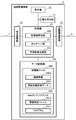
- the air conditioning management device 2 is installed in a place where only persons concerned cannot enter, such as a management room in the building, and comprehensively manages (monitors and controls) the air conditioner group 8. As shown in FIG. 2, the air conditioning management device 2 includes a display unit 20, an operation receiving unit 21, an air conditioner communication unit 22, a terminal communication unit 23, a data storage unit 24, and a control unit 25.
- the display unit 20 is configured by a display device such as a CRT display, a liquid crystal display, an organic EL display, or a plasma display.
- the display unit 20 displays a management screen for managing the operating state of the air conditioner group 8 under the control of the control unit 25.
- the management screen includes a monitoring screen for monitoring the operating state of the air conditioner group 8, an operation screen for controlling the air conditioner group 8, and the like.
- the operation accepting unit 21 includes, for example, a keyboard, a mouse, a keypad, a touch pad, a touch panel, and the like.
- the operation reception unit 21 receives an operation by an administrator or the like, and sends a signal related to the received operation to the control unit 25.
- the operation receiving unit 21 is a touch panel, it is installed on the display unit 20.
- the air conditioner communication unit 22 functions as an interface of the communication line 6 that is a dedicated communication line.
- the air conditioning management device 2 transmits and receives data to and from each air conditioner 3 via the air conditioner communication unit 22.
- the communication line 6 is not necessarily a dedicated communication line, and may be configured using a general-purpose communication line such as a LAN or an RS-485 interface.
- the terminal communication unit 23 functions as an interface for the communication line 7.
- the air conditioning management device 2 transmits and receives data to and from the monitoring terminal 4 via the terminal communication unit 23.
- the communication line 7 is a communication path capable of general-purpose communication such as a wired LAN or a wireless LAN.
- HTTP Hypertext Transfer Protocol
- Web browser is adopted as a communication protocol between the air conditioning management device 2 and the monitoring terminal 4.
- the protocol is not limited to HTTP, and other protocols such as WebSocket may be used.
- the data storage unit 24 (storage means) includes a readable / writable non-volatile semiconductor memory such as a flash memory, a hard disk drive, or the like.
- the data storage unit 24 stores data necessary for monitoring and controlling the air conditioner group 8. Specifically, the data storage unit 24 stores air conditioner data 240 and Web content data 241.
- the air conditioner data 240 includes connection information 2400 and operation state management data 2401.
- the connection information 2400 is information necessary for communicating with each air conditioner 3, such as the address, identification number, operation group number, model identification information of each air conditioner 3.
- the operation state management data 2401 is for managing the current operation state of each air conditioner 3 (for example, operation mode during operation / stop, operation mode such as cooling / heating / air blowing, set temperature, indoor temperature, indoor humidity, etc.). It is data.
- the operation state management data 2401 is updated as needed by data transmission / reception with each air conditioner 3.
- Web content data 241 is data defining Web content displayed on the Web browser of the monitoring terminal 4.
- the Web content data 241 includes a screen configuration file 2410 and a program 2411.
- the screen configuration file 2410 is a group of files created in a description language such as HTML (HyperText Markup Language).
- the monitoring terminal 4 can display a management screen such as a monitoring screen or an operation screen on the Web browser by the screen configuration file 2410 acquired from the air conditioning management device 2.
- the program 2411 is a program downloaded and executed by the monitoring terminal 4. By executing the program 2411, the monitoring terminal 4 can perform various types of communication with the air conditioning management device 2, and can acquire data related to the air conditioner 3.
- the program 2411 is described by, for example, JavaScript (registered trademark), Java (registered trademark) applet, or Flash (registered trademark).
- the data storage unit 24 stores one or a plurality of programs for managing the operating state of the air conditioner 3 (not shown).
- control unit 25 includes a CPU (Central Processing Unit), a ROM (Read Only Memory), a RAM (Random Access Memory), and the like, and performs overall control of the air conditioning management device 2. Detailed functions of the control unit 25 will be described later.
- CPU Central Processing Unit
- ROM Read Only Memory
- RAM Random Access Memory
- the monitoring terminal 4 (terminal device) is a personal computer equipped with a general-purpose Web browser function, receives Web content data 241 from the air conditioning management device 2 via the communication line 7, and receives Web content data.
- a management screen such as a monitoring screen or an operation screen is displayed in accordance with 241.
- the air conditioning management device 2 and the monitoring terminal 4 of each user are connected to a general-purpose communication line 7 constituting a local LAN (or a dedicated LAN), and the web browser of the monitoring terminal 4 is connected to the web in the air conditioning management device 2.
- the management screen can be displayed on the monitoring terminal 4 by inputting the URL (Uniform Resource Locator) of the content data 241.
- URL Uniform Resource Locator
- the monitoring terminal 4 includes a display unit 40, an operation receiving unit 41, a communication unit 42, a data storage unit 43, and a control unit 44.
- the display unit 40 includes a display device such as a CRT display, a liquid crystal display, an organic EL display, or a plasma display, and displays various types of information. For example, the display unit 40 displays a management screen for the air conditioner group 8 on the web browser based on the web content data 241 acquired from the air conditioning management device 2 under the control of the control unit 44.
- a display device such as a CRT display, a liquid crystal display, an organic EL display, or a plasma display
- the operation reception unit 41 is composed of, for example, a keyboard, a mouse, a keypad, a touchpad, a touch panel, and the like.
- a signal related to the operation is sent to the control unit 44.
- the user can perform desired operation
- the operation reception part 41 is a touch panel, it is installed on the display part 40.
- the communication unit 42 functions as an interface for the communication line 7.
- the monitoring terminal 4 transmits and receives data to and from the air conditioning management device 2 via the communication unit 42.
- the data storage unit 43 includes a readable / writable non-volatile semiconductor memory such as a flash memory, a hard disk drive, or the like.
- the data storage unit 43 stores various data necessary for the control unit 44 to perform management screen display processing.
- control unit 44 includes a CPU, a ROM, a RAM, and the like, and performs overall control of the monitoring terminal 4. Characteristically, the control unit 44 acquires the Web content data 241 from the air conditioning management device 2 and performs a process for displaying a management screen on the display unit 40 based on the acquired Web content data 241. Functionally, the control unit 44 includes a screen configuration file analysis unit 440 and a program execution unit 441.
- the screen configuration file analysis unit 440 reads the screen configuration file 2410 in the Web content data 241 acquired from the air conditioning management device 2, and generates screen data that serves as a base screen of the management screen.
- the program execution unit 441 communicates with the air conditioning management device 2 via the communication unit 42 by executing the program 2411 of the Web content data 241, generates a management screen by acquiring necessary data, and displays the display unit 40.
- the program execution unit 441 includes a data communication management unit 4410 and a management screen generation unit 4411.
- the data communication management unit 4410 communicates with the air conditioning management device 2 by executing the program 2411 periodically or when there is an instruction from the user, and acquires data such as the air conditioner data 240.
- the management screen generation unit 4411 generates a management screen obtained by combining the data acquired by the data communication management unit 4410 with the screen data generated by the screen configuration file analysis unit 440 and displays the management screen on the display unit 40.
- the management screen generation unit 4411 generates a management screen by embedding various information indicated by the data acquired by the data communication management unit 4410 in the screen data generated by the screen configuration file analysis unit 440.
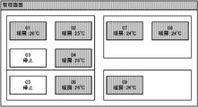
- An example of the management screen displayed on the monitoring terminal 4 is shown in FIG.
- FIG. 5 is a flowchart showing a procedure of management screen display processing executed by the monitoring terminal 4.
- the management screen display process is started when the user inputs the URL of the Web content data 241 in the air conditioning management device 2 to the Web browser of the monitoring terminal 4.
- the control unit 44 acquires the Web content data 241 from the air conditioning management device 2 (step S101). Then, the control unit 44 analyzes the screen configuration file 2410 in the acquired Web content data 241 and generates screen data that becomes a base screen of the management screen (step S102).
- control unit 44 executes the program 2411 included in the acquired web content data 241 (step S103). And the control part 44 communicates with the air-conditioning management apparatus 2 according to the content described in the program 2411, and acquires the data (for example, driving
- control unit 44 generates a management screen in which various information indicated by the data acquired in step S104 is embedded in the screen data generated in step S102, and displays the management screen on the display unit 40 (step S105).
- the management screen display process ends.
- the control unit 25 of the air conditioning management device 2 functionally includes an air conditioner management unit 250, a Web server unit 251, and a management screen generation unit 252.
- Each of these functional units is realized by a CPU or the like executing one or a plurality of programs (not shown) for managing the operation state of the air conditioner 3 stored in the data storage unit 24.
- the air conditioner management unit 250 executes processing similar to that of this type of conventional air conditioning management device, for example, processing for controlling the operation of the air conditioner 3 in accordance with an operation instruction received from the user via the management screen.
- the air conditioner management unit 250 receives the above-described operation state data transmitted from the air conditioner 3 via the air conditioner communication unit 22, the air conditioner management unit 250 manages the operation state of the air conditioner data 240 based on the received operation state data. The contents of the data 2401 are updated.
- the Web server unit 251 transmits the Web content data 241, the operation state management data 2401, etc. to the requesting monitoring terminal 4.
- the management screen generation unit 252 generates a management screen for managing the operation state of the air conditioner group 8 and displays the management screen on the display unit 20.
- the management screen includes a monitoring screen for monitoring the operating state of the air conditioner group 8, an operation screen for controlling the air conditioner group 8 or the specific air conditioner 3, and the like.
- the management screen generation unit 252 performs switching or updating of the management screen according to a user operation, and updates the management screen in accordance with the update of the content of the operation state management data 2401.
- the management screen generation unit 252 generates and displays a management screen based on the Web content data 241 and the air conditioner data 240 stored in the data storage unit 24. More specifically, the management screen generation unit 252 reads the screen configuration file 2410 in the Web content data 241 and generates screen data that becomes a base screen of the management screen. Then, the management screen generation unit 252 generates a management screen by combining the data acquired from the air conditioner data 240 with the generated screen data, that is, by embedding various information indicated by the acquired data. Therefore, the management screen generation unit 252 has a function similar to that of a general Web browser installed in the monitoring terminal 4. However, the function of the management screen generation unit 252 has the following features.
- a main field for displaying a Web page here, a management screen
- a screen frame a field for displaying a title
- a field for displaying a tool such as a “return” button (tool field)
- a field for inputting a URL URL field
- a status field for displaying a reading status etc.
- the management screen generation unit 252 hides a plurality of fields including at least the URL field, excluding the main body field, from among the fields described above.
- the management screen generation unit 252 converts the resolution of the image data defined by the screen configuration file 2410 included in the Web content data 241 to an appropriate value based on the specification of the display unit 20 and manages the management screen. Is generated. It is assumed that data related to the specification of the display unit 20 (monitor specification data) is stored in the data storage unit 24 in advance. Note that the monitor specification data can be appropriately changed by an operation through the user operation receiving unit 21.
- FIG. 6 shows an example of the management screen generated in the management screen generation unit 252 and displayed on the display unit 20 as described above.
- FIG. 7 is a flowchart showing the procedure of the air conditioning management process executed by the air conditioning management device 2.
- the air conditioning management process is started when the power of the air conditioning management device 2 is turned on.
- the management screen generation unit 252 generates a top screen (main screen) of the management screen based on the Web content data 241 and the air conditioner data 240 stored in the data storage unit 24, and displays it on the display unit 20 ( Step S201).
- step S202 When the user performs an operation via the displayed management screen (step S202; YES), the management screen generation unit 252 switches or updates the management screen (step S203). On the other hand, when the operation by the user is not performed (step S202; NO), the process of the air conditioning management device 2 proceeds to step S206.
- step S204 When the user's operation is related to the control instruction of the air conditioner 3 (step S204; YES), the air conditioner management unit 250 generates control data according to the control instruction, and the air conditioner group 8 or the designated air conditioner. It transmits to the machine 3 (step S205). On the other hand, when the user operation is not related to the control instruction of the air conditioner 3 (step S204; NO), the processing of the air conditioning management device 2 proceeds to step S206.
- step S206 it is determined whether or not the content of the operation state management data 2401 stored in the data storage unit 24 has been updated.
- the management screen generation unit 252 updates the management screen based on the updated content (step S207).
- step S208 the process of the air-conditioning management apparatus 2 transfers to step S208.
- step S208 it is determined whether or not there is a data request from the monitoring terminal 4.
- the web server unit 251 transmits the web content data 241 or the air conditioner data 240 to the requesting monitoring terminal 4 (step S209).
- step S209 or when there is no request from the monitoring terminal 4 step S208; NO
- the processing of the air conditioning management device 2 returns to step S202.
- the air conditioning management device 2 includes the management screen generation unit 252 having a function similar to that of the Web browser. Then, the management screen generation unit 252 generates a management screen based on the Web content data 241 that defines the Web content displayed on the Web browser of the monitoring terminal 4 and displays the management screen on the display unit 20. This allows the air conditioning management device 2 and the monitoring terminal 4 to share the design concept related to the display function of the management screen, thereby reducing the number of man-hours for development and maintenance (changes, corrections, etc.). Reduction can be achieved.
- the management screen generation unit 252 since the management screen generation unit 252 generates a management screen based on the Web content data 241, the air conditioning management device 2 does not need to hold dedicated screen data separately, and the memory capacity can be reduced. Can be reduced.
- management screen generation unit 252 generates and displays a management screen in which a screen frame and a specific display field in a general Web browser screen configuration such as a URL field are removed. No discomfort to the person. Therefore, it is possible to provide visibility and operability that are comparable to conventional ones.
- the management screen generation unit 252 generates a management screen by converting the resolution of the image data defined by the screen configuration file 2410 included in the Web content data 241 into an appropriate value based on the specification of the display unit 20. For this reason, it is not necessary to tune the display according to each of the air conditioning management device 2 and the monitoring terminal 4, and the development cost, manufacturing cost, and maintenance cost can be further reduced.
- the management screen generation unit 252 enlarges the operation target component (icon, scroll button, scroll bar, etc.) constituting the management screen according to a predetermined condition or detects a touch operation detection range (allowable range). ) May be enlarged. If it does in this way, the further improvement of visibility and operability of an administrator etc. can be aimed at.
- the operation target component icon, scroll button, scroll bar, etc.
- the administrator or the like can set via the operation reception unit 21 whether or not to remove the screen frame and the specific display field in the general Web browser screen configuration such as the URL field. Also good.
- the management screen generation unit 252 determines whether or not to remove the screen frame and the specific display field according to the setting.
- each function unit of the air conditioning management device 2 is executed by executing one or more programs for managing the operation state of the air conditioner 3 stored in the data storage unit 24 by the CPU or the like. (See FIG. 2) was realized.
- all or part of the functional units of the air conditioning management device 2 may be realized by dedicated hardware.
- the dedicated hardware is, for example, a single circuit, a composite circuit, a programmed processor, an ASIC (Application Specific Integrated Circuit), an FPGA (Field-Programmable Gate Array), or a combination thereof.
- the program executed by the air conditioning management device 2 is a CD-ROM (Compact Disc Read Only Memory), DVD (Digital Versatile Disc), MO (Magneto-Optical Disk), USB memory, memory card, etc. It is also possible to store and distribute in a computer-readable recording medium. And it is also possible to make the said computer function as the air-conditioning management apparatus 2 in the said embodiment by installing this program in a specific or general purpose computer.
- the above program may be stored in a disk device or the like included in a server device on a communication network such as the Internet, and may be downloaded onto a computer, for example, superimposed on a carrier wave.
- the above-described processing can also be achieved by starting and executing a program while transferring it via a communication network.
- the above-described processing can also be achieved by executing all or part of the program on the server device and executing the program while the computer transmits and receives information regarding the processing via the communication network.
- the present invention can be suitably employed in an air conditioning management system installed in an office building or the like.
- Air conditioning management system 1 Air conditioning management system, 2 Air conditioning management device, 3 Air conditioner, 4 Monitoring terminal, 5 Remote controller, 6, 7 Communication line, 8 Air conditioner group, 20, 40 Display unit, 21, 41 Operation reception unit, 22 Air conditioner communication Unit, 23 terminal communication unit, 24, 43 data storage unit, 25, 44 control unit, 42 communication unit, 240 air conditioner data, 241 web content data, 250 air conditioner management unit, 251 web server unit, 252, 4411 management screen Generation unit, 440 screen configuration file analysis unit, 441 program execution unit, 2400 connection information, 2401 operation state management data, 2410 screen configuration file, 2411 program, 4410 data communication management unit
Landscapes
- Engineering & Computer Science (AREA)
- Chemical & Material Sciences (AREA)
- Combustion & Propulsion (AREA)
- Mechanical Engineering (AREA)
- General Engineering & Computer Science (AREA)
- Human Computer Interaction (AREA)
- Air Conditioning Control Device (AREA)
Abstract
空調管理装置(2)において、データ記憶部(24)は、Webコンテンツデータ(241)と、空調機に関する空調機データ(240)を記憶する。Webサーバ部(251)は、端末装置からの要求に応答してWebコンテンツデータ(241)を端末通信部(23)を介して端末装置に送信する。管理画面生成部(252)は、Webコンテンツデータ(241)に基づく画面データに空調機データ(240)を合成することで空調機の運転状態を管理するための管理画面を生成し、表示部(20)に出力する。
Description
本発明は、空調管理装置及びプログラムに関する。
ビルに設置された複数の設備の統合的な管理を目的としたビル管理システムは広く知られている。また、一般的なWebブラウザを搭載した端末装置により、LAN(Local Area Network)を介してビル管理システムにアクセスして、空調機等の設備の運転状態の監視や制御を行えるようにした技術(例えば、特許文献1)も知られている。
特許文献1に開示される技術では、ビル管理システムの内部バスとLANとの間に運営管理装置が設けられている。かかる運営管理装置は、LANに接続する端末装置からの要求に基づき、ビル管理システムにおける空調機等の運転状態を収集し、ハイパーテキスト形式の画面表示情報に編集して要求元の端末装置に送信する。
特許文献1のビル管理システムには、中央監視室に駐在するオペレータに空調機等の運転状態を表示し、且つ空調機等の運転を制御するための入力をオペレータから受け付けるためのマンマシン装置が設けられている。しかしながら、このマンマシン装置は、ハイパーテキスト形式での画面表示を採用していないため、画面表示機能に係る設計思想を端末装置と共通化できず、開発やメンテナンス等にかかるコストの削減化を妨げているという課題がある。
本発明は、上記課題を解決するためになされたものであり、画面表示機能についての開発コスト等の削減が図れる空調管理装置及びプログラムを提供することを目的とする。
上記目的を達成するため、本発明に係る空調管理装置は、
空調機の運転状態を管理するための管理画面を表示する表示手段と、
端末装置と通信する端末通信手段と、
Webコンテンツデータと、前記空調機に関する空調機データを記憶する記憶手段と、
前記端末装置からの要求に応答して前記Webコンテンツデータを前記端末通信手段を介して前記端末装置に送信するWebサーバ手段と、
前記Webコンテンツデータに基づく画面データに前記空調機データを合成することで前記管理画面を生成し、前記表示手段に出力する管理画面生成手段とを備える。
空調機の運転状態を管理するための管理画面を表示する表示手段と、
端末装置と通信する端末通信手段と、
Webコンテンツデータと、前記空調機に関する空調機データを記憶する記憶手段と、
前記端末装置からの要求に応答して前記Webコンテンツデータを前記端末通信手段を介して前記端末装置に送信するWebサーバ手段と、
前記Webコンテンツデータに基づく画面データに前記空調機データを合成することで前記管理画面を生成し、前記表示手段に出力する管理画面生成手段とを備える。
本発明によれば、空調管理装置は、端末装置に提供するWebコンテンツデータに基づく画面データに空調機データを合成することで管理画面を表示するため、画面表示機能に係る開発コストの削減が図れる。
以下、本発明の実施形態について図面を参照して詳細に説明する。
図1は、本発明の実施形態に係る空調管理システム1の全体構成を示す図である。空調管理システム1は、例えば、オフィスビル等の建物の空調を管理するためのシステムであり、図1に示すように、空調管理装置2と、複数の空調機3と、複数の監視端末4と、リモートコントローラ5とから構成される。
空調管理装置2と、複数の空調機3の各々と、リモートコントローラ5とは、通信線6を介して相互に通信可能となるように接続されている。また、空調管理装置2と複数の監視端末4の各々とは、通信線7を介して相互に通信可能となるように接続されている。
複数の空調機3は、予め定めた居室空間において異なる位置にそれぞれ設置され、空調管理装置2の制御の下で監視、制御される。空調機3は、空調管理装置2からの制御データを受信すると、かかる制御データに基づいた動作を行う。即ち、空調機3は、受信した制御データの内容に従って、運転の開始/停止、冷房,暖房,除湿,送風等の運転モードの切り替え、設定温度の変更や風量等の変更を行う。以下、複数の空調機3を総称して空調機群8とも呼ぶ。
リモートコントローラ5は、空調機群8が設置される居室空間への出入口付近に設置される。リモートコントローラ5は、ユーザからの入力操作を受け付け、受け付けた入力操作に基づく制御データを空調機群8又はユーザにより指定された1又は複数の空調機3に送信する。このようにしてリモートコントローラ5から送信された制御データを受信した空調機3は、受信した制御データに基づいた運転を行う。その場合、空調機3は、リモートコントローラ5からの制御データに基づいて変更した自機の運転状態に係るデータ(運転状態データ)を空調管理装置2に送信する。
空調管理装置2は、当該建物内の管理室等、関係者以外が立ち入ることのできない場所に設置され、空調機群8を統括的に管理(監視、制御)する。空調管理装置2は、図2に示すように、表示部20と、操作受付部21と、空調機通信部22と、端末通信部23と、データ記憶部24と、制御部25とを備える。
表示部20は、例えば、CRTディスプレイ、液晶ディスプレイ、有機ELディスプレイ、プラズマディスプレイ等の表示デバイスで構成される。表示部20は、制御部25の制御の下、空調機群8の運転状態を管理するための管理画面を表示する。管理画面には、空調機群8の運転状態を監視するための監視画面、空調機群8を制御するための操作画面等が含まれる。
操作受付部21は、例えば、キーボード、マウス、キーパッド、タッチパッドやタッチパネル等で構成される。操作受付部21は、管理者等による操作を受け付け、受け付けた操作に係る信号を制御部25に送出する。なお、操作受付部21がタッチパネルである場合には、表示部20上に設置される。
空調機通信部22は、専用の通信線である通信線6のインタフェースとして機能する。空調管理装置2は、空調機通信部22を介して各空調機3とデータの送受信を行う。なお、通信線6は、必ずしも専用の通信線である必要はなく、汎用的な通信線であるLANやRS-485インタフェースなどを用いた構成としてもよい。
端末通信部23(端末通信手段)は、通信線7のインタフェースとして機能する。空調管理装置2は、端末通信部23を介して監視端末4とデータの送受信を行う。通信線7は、例えば、有線LANや無線LANなど、汎用的な通信が可能な通信路である。本実施形態では、空調管理装置2と監視端末4との間の通信プロトコルとして、一般にWebブラウザで利用されるHTTP(Hypertext Transfer Protocol)を採用する。しかし、HTTPに限定されず、WebSocketなどの他のプロトコルを用いてもよい。
データ記憶部24(記憶手段)は、フラッシュメモリ等の読み書き可能な不揮発性の半導体メモリやハードディスクドライブ等から構成される。データ記憶部24は、空調機群8の監視や制御を行うために必要となるデータを記憶する。具体的には、データ記憶部24は、空調機データ240と、Webコンテンツデータ241とを記憶する。
空調機データ240には、接続情報2400と、運転状態管理データ2401とが含まれる。接続情報2400は、各空調機3のアドレス、識別番号、操作グループ番号、機種識別情報など、各空調機3と通信するために必要な情報である。運転状態管理データ2401は、各空調機3の現在の運転状態(例えば、運転中/停止中、冷房/暖房/送風などの運転モード、設定温度、室内温度、室内湿度など)を管理するためのデータである。運転状態管理データ2401は、各空調機3とのデータ送受信により随時更新される。
Webコンテンツデータ241は、監視端末4のWebブラウザ上に表示されるWebコンテンツを定義するデータである。Webコンテンツデータ241には、画面構成ファイル2410とプログラム2411とが含まれる。
画面構成ファイル2410は、HTML(HyperText Markup Language)等の記述言語で作成されたファイル群である。監視端末4は、空調管理装置2から取得した画面構成ファイル2410により、Webブラウザ上に監視画面や操作画面等の管理画面を表示することが可能となる。
プログラム2411は、監視端末4によりダウンロードされて実行されるプログラムである。プログラム2411を実行することにより、監視端末4は、空調管理装置2との間で各種の通信が可能となり、空調機3に関するデータを取得することが可能となる。プログラム2411は、例えば、JavaScript(登録商標)、Java(登録商標)アプレット、またはFlash(登録商標)などで記述されている。
なお、上記の他にも、データ記憶部24は、図示はしないが、空調機3の運転状態を管理するための1又は複数のプログラムを記憶する。
制御部25は、何れも図示しないが、CPU(Central Processing Unit)、ROM(Read Only Memory)、RAM(Random Access Memory)等を備え、空調管理装置2を統括制御する。制御部25の詳細な機能については後述する。
図1に戻り、監視端末4(端末装置)は、汎用的なWebブラウザ機能を搭載したパーソナルコンピュータであり、通信線7を介して空調管理装置2からWebコンテンツデータ241を受信し、Webコンテンツデータ241に従って監視画面や操作画面等の管理画面を表示する。例えば、空調管理装置2及び各利用者の監視端末4を構内LAN(又は専用のLAN)を構成する汎用の通信線7に接続し、監視端末4のWebブラウザに、空調管理装置2内のWebコンテンツデータ241のURL(Uniform Resource Locator)を入力することで、監視端末4に管理画面を表示することができる。以下、監視端末4の構成について詳細に説明する。
図3に示すように、監視端末4は、表示部40と、操作受付部41と、通信部42と、データ記憶部43と、制御部44とを備える。
表示部40は、CRTディスプレイ、液晶ディスプレイ、有機ELディスプレイ、プラズマディスプレイ等の表示デバイスで構成され、各種の情報を表示する。例えば、表示部40は、制御部44の制御の下、空調管理装置2から取得したWebコンテンツデータ241に基づいて、Webブラウザ上に空調機群8の管理画面を表示する。
操作受付部41は、例えば、キーボード、マウス、キーパッド、タッチパッドやタッチパネル等で構成される。ユーザが、操作受付部41から所望の操作を行うと、その操作に係る信号が制御部44に送出される。これにより、ユーザは、例えば、管理画面の切り替えや、空調機群8あるいは特定の空調機3に所望の動作を実行させることができる。なお、操作受付部41がタッチパネルである場合には、表示部40上に設置される。
通信部42は、通信線7のインタフェースとして機能する。監視端末4は、通信部42を介して空調管理装置2とデータの送受信を行う。
データ記憶部43は、フラッシュメモリ等の読み書き可能な不揮発性の半導体メモリやハードディスクドライブ等から構成される。データ記憶部43は、制御部44が管理画面の表示処理を行うために必要となる各種データを記憶する。
制御部44は、何れも図示しないが、CPU、ROM、RAM等を備え、監視端末4を統括制御する。特徴的には、制御部44は、空調管理装置2からWebコンテンツデータ241を取得し、取得したWebコンテンツデータ241に基づいて、表示部40に管理画面を表示するための処理を行う。制御部44は、機能的には、画面構成ファイル解析部440と、プログラム実行部441とを備える。
画面構成ファイル解析部440は、空調管理装置2から取得したWebコンテンツデータ241内の画面構成ファイル2410を読み込み、管理画面のベース画面となる画面データを生成する。
プログラム実行部441は、Webコンテンツデータ241のプログラム2411を実行することにより、通信部42を介して空調管理装置2と通信を行い、必要なデータを取得することで管理画面を生成し、表示部40に表示する。プログラム実行部441には、データ通信管理部4410と、管理画面生成部4411とが含まれる。
データ通信管理部4410は、定期的に又はユーザからの指示があった際に、プログラム2411を実行することにより空調管理装置2と通信を行い、空調機データ240等のデータを取得する。
管理画面生成部4411は、画面構成ファイル解析部440が生成した画面データにデータ通信管理部4410が取得したデータを合成した管理画面を生成し、表示部40に表示する。例えば、管理画面生成部4411は、画面構成ファイル解析部440が生成した画面データに、データ通信管理部4410が取得したデータが示す各種の情報を埋め込む等して管理画面を生成する。監視端末4で表示される管理画面の一例を図4に示す。
図5は、監視端末4で実行される管理画面表示処理の手順を示すフローチャートである。管理画面表示処理は、ユーザにより監視端末4のWebブラウザに、空調管理装置2内のWebコンテンツデータ241のURLが入力されることで開始される。
制御部44は、空調管理装置2からWebコンテンツデータ241を取得する(ステップS101)。そして、制御部44は、取得したWebコンテンツデータ241内の画面構成ファイル2410を解析して管理画面のベース画面となる画面データを生成する(ステップS102)。
続いて、制御部44は、取得したWebコンテンツデータ241に含まれるプログラム2411を実行する(ステップS103)。そして、制御部44は、プログラム2411に記述された内容に従って、空調管理装置2と通信を行い、空調機3に関するデータ(例えば、運転状態管理データ2401)を取得する(ステップS104)。
続いて、制御部44は、ステップS102で生成した画面データに、ステップS104で取得したデータが示す各種の情報を埋め込んだ管理画面を生成し、表示部40に表示する(ステップS105)。以上で管理画面表示処理は終了する。
図2に戻り、空調管理装置2の制御部25は、機能的には、空調機管理部250と、Webサーバ部251と、管理画面生成部252とを備える。これらの各機能部は、CPU等が、データ記憶部24に記憶されている、空調機3の運転状態を管理するための図示しない1又は複数のプログラムを実行することで実現される。
空調機管理部250は、従来のこの種の空調管理装置と同様の処理、例えば、管理画面を介してユーザから受け付けた操作指示に従って空調機3の運転動作を制御する処理を実行する。また、空調機管理部250は、空調機3から送信された上述の運転状態データを空調機通信部22を介して受信すると、受信した運転状態データに基づいて、空調機データ240の運転状態管理データ2401の内容を更新する。
Webサーバ部251は、監視端末4からの要求に応答して、Webコンテンツデータ241や運転状態管理データ2401等を要求元の監視端末4に送信する。
管理画面生成部252は、空調機群8の運転状態を管理するための管理画面を生成し、表示部20に表示する。上述したように、管理画面には、空調機群8の運転状態を監視するための監視画面、空調機群8又は特定の空調機3を制御するための操作画面等が含まれる。また、管理画面生成部252は、ユーザの操作に応じて管理画面の切り替えや更新を行ったり、運転状態管理データ2401の内容の更新に伴い管理画面の更新を行う。
管理画面生成部252は、データ記憶部24に記憶されるWebコンテンツデータ241と空調機データ240に基づいて管理画面の生成及び表示を行う。より詳細には、管理画面生成部252は、Webコンテンツデータ241内の画面構成ファイル2410を読み込み、管理画面のベース画面となる画面データを生成する。そして、管理画面生成部252は、生成した画面データに空調機データ240から取得したデータを合成することで、即ち、取得したデータが示す各種の情報を埋め込む等することで管理画面を生成する。このため、管理画面生成部252は、監視端末4に搭載される一般的なWebブラウザと類似の機能を備える。ただし、管理画面生成部252の機能には、以下のような特徴が備わっている。
(1)一般的なWebブラウザの画面構成における画面枠や特定の表示フィールドの除去
一般的なWebブラウザにおいては、図4に示すように、Webページ(ここでは、管理画面)を表示する本体フィールドの他、画面枠や、タイトルを表示するフィールド、「戻る」ボタン等のツールを表示するフィールド(ツールフィールド)、URLを入力するためのフィールド(URLフィールド)、読み込みの状態等を表示する状態フィールド等の各種のフィールドが表示される。管理画面生成部252は、上記の各フィールドの内、本体フィールドを除く、少なくともURLフィールドを含む複数のフィールドを非表示とする。
一般的なWebブラウザにおいては、図4に示すように、Webページ(ここでは、管理画面)を表示する本体フィールドの他、画面枠や、タイトルを表示するフィールド、「戻る」ボタン等のツールを表示するフィールド(ツールフィールド)、URLを入力するためのフィールド(URLフィールド)、読み込みの状態等を表示する状態フィールド等の各種のフィールドが表示される。管理画面生成部252は、上記の各フィールドの内、本体フィールドを除く、少なくともURLフィールドを含む複数のフィールドを非表示とする。
(2)解像度の変換
管理画面生成部252は、Webコンテンツデータ241に含まれる画面構成ファイル2410で定義される画像データの解像度を表示部20の仕様に基づいて適切な値に変換して管理画面を生成する。表示部20の仕様に関するデータ(モニタ仕様データ)は、予めデータ記憶部24に記憶されているものとする。なお、モニタ仕様データは、ユーザの操作受付部21を介した操作により適宜変更可能である。
管理画面生成部252は、Webコンテンツデータ241に含まれる画面構成ファイル2410で定義される画像データの解像度を表示部20の仕様に基づいて適切な値に変換して管理画面を生成する。表示部20の仕様に関するデータ(モニタ仕様データ)は、予めデータ記憶部24に記憶されているものとする。なお、モニタ仕様データは、ユーザの操作受付部21を介した操作により適宜変更可能である。
上記のようにして管理画面生成部252に生成され、表示部20に表示される管理画面の一例を図6に示す。
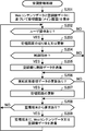
図7は、空調管理装置2で実行される空調管理処理の手順を示すフローチャートである。空調管理処理は、空調管理装置2の電源がONになると開始される。
先ず、管理画面生成部252は、データ記憶部24に記憶されているWebコンテンツデータ241と空調機データ240に基づいて管理画面のトップ画面(メイン画面)を生成し、表示部20に表示する(ステップS201)。
表示された管理画面を介してユーザにより操作が行われると(ステップS202;YES)、管理画面生成部252は、管理画面の切り替え又は更新を行う(ステップS203)。一方、ユーザによる操作が行われていない場合(ステップS202;NO)、空調管理装置2の処理は、ステップS206へ移行する。
ユーザの操作が空調機3の制御指示に関するものである場合(ステップS204;YES)、空調機管理部250は、かかる制御指示に応じた制御データを生成し、空調機群8又は指定された空調機3に送信する(ステップS205)。一方、ユーザの操作が空調機3の制御指示に関するものでない場合(ステップS204;NO)、空調管理装置2の処理は、ステップS206へ移行する。
ステップS206では、データ記憶部24に記憶されている運転状態管理データ2401の内容が更新されたか否かが判別される。更新されている場合(ステップS206;YES)、管理画面生成部252は、更新された内容に基づいて管理画面の更新を行う(ステップS207)。一方、更新されていない場合(ステップS206;NO)、空調管理装置2の処理は、ステップS208へ移行する。
ステップS208では、監視端末4からデータの要求があったか否かが判別される。要求があった場合(ステップS208;YES)、Webサーバ部251は、要求元の監視端末4に、Webコンテンツデータ241又は空調機データ240を送信する(ステップS209)。ステップS209の後、又は、監視端末4からの要求が無かった場合(ステップS208;NO)、空調管理装置2の処理は、ステップS202へ戻る。
以上説明したように、本発明の実施形態に係る空調管理システム1では、空調管理装置2は、Webブラウザと類似の機能を有する管理画面生成部252を備える。そして、管理画面生成部252は、監視端末4のWebブラウザ上に表示されるWebコンテンツを定義したWebコンテンツデータ241に基づいて管理画面を生成し、表示部20に表示する。これにより、空調管理装置2と監視端末4とで、管理画面の表示機能に係る設計思想を共通化できるため、開発及びメンテナンス(変更、修正等)の工数を低減でき、開発コスト及びメンテナンスコストの削減が図れる。
また、管理画面生成部252は、Webコンテンツデータ241に基づいて管理画面を生成するので、空調管理装置2は、専用の画面データを別途保持する必要がなく、メモリ容量の削減が図れ、製造コストの削減が図れる。
また、管理画面生成部252は、URLフィールド等の一般的なWebブラウザの画面構成における画面枠や特定の表示フィールドを除去した管理画面を生成して表示するため、空調管理装置2を操作する管理者等に違和感を与えることがない。したがって、従来と遜色がない視認性及び操作性を提供できる。
また、管理画面生成部252は、Webコンテンツデータ241に含まれる画面構成ファイル2410で定義される画像データの解像度を表示部20の仕様に基づいて適切な値に変換して管理画面を生成する。このため、空調管理装置2と監視端末4の各々に合わせた表示のチューニング等が不要となり、開発コスト、製造コスト及びメンテナンスコストの削減化がより図れる。
なお、本発明は、上記の実施形態に限定されず、本発明の要旨を逸脱しない範囲での種々の変更は勿論可能である。
例えば、管理画面生成部252は、管理画面を構成する操作対象部品(アイコン、スクロールボタン、スクロールバー等)については、予め定めた条件に従って、拡大したり、あるいは、タッチ操作の検出範囲(許容範囲)を拡大してもよい。このようにすると、管理者等の視認性及び操作性のさらなる向上が図れる。
また、管理画面において、URLフィールド等の一般的なWebブラウザの画面構成における画面枠や特定の表示フィールドを除去するか否かの設定を管理者等が操作受付部21を介して行えるようにしてもよい。この場合、管理画面生成部252は、かかる設定に応じて画面枠や特定の表示フィールドを除去するか否かを決定する。
上記の実施形態では、CPU等によってデータ記憶部24に記憶されている、空調機3の運転状態を管理するための1又は複数のプログラムが実行されることで、空調管理装置2の各機能部(図2参照)が実現された。しかし、空調管理装置2の機能部の全部又は一部が、専用のハードウェアで実現されるようにしてもよい。専用のハードウェアとは、例えば、単一回路、複合回路、プログラム化されたプロセッサ、ASIC(Application Specific Integrated Circuit)、FPGA(Field-Programmable Gate Array)、又は、これらの組み合わせ等である。
また、上記実施形態において、空調管理装置2によって実行されるプログラムは、CD-ROM(Compact Disc Read Only Memory)、DVD(Digital Versatile Disc)、MO(Magneto-Optical Disk)、USBメモリ、メモリカード等のコンピュータ読み取り可能な記録媒体に格納して配布することも可能である。そして、かかるプログラムを特定の又は汎用のコンピュータにインストールすることによって、当該コンピュータを上記実施形態における空調管理装置2として機能させることも可能である。
また、上記のプログラムをインターネット等の通信ネットワーク上のサーバ装置が有するディスク装置等に格納しておき、例えば、搬送波に重畳させて、コンピュータにダウンロード等するようにしてもよい。また、通信ネットワークを介してプログラムを転送しながら起動実行することによっても、上述の処理を達成することができる。さらに、プログラムの全部又は一部をサーバ装置上で実行させ、その処理に関する情報をコンピュータが通信ネットワークを介して送受信しながらプログラムを実行することによっても、上述の処理を達成することができる。
なお、上述の機能を、OS(Operating System)が分担して実現する場合又はOSとアプリケーションとの協働により実現する場合等には、OS以外の部分のみを上記の記録媒体に格納して配布してもよく、また、コンピュータにダウンロード等してもよい。
本発明は、広義の精神と範囲を逸脱することなく、様々な実施形態及び変形が可能である。また、上述した実施形態は、本発明を説明するためのものであり、本発明の範囲を限定するものではない。つまり、本発明の範囲は、実施形態ではなく、請求の範囲によって示される。そして、請求の範囲内及びそれと同等の発明の意義の範囲内で施される様々な変形が、本発明の範囲内とみなされる。
本発明は、オフィスビル等に設置される空調管理システムに好適に採用され得る。
1 空調管理システム、2 空調管理装置、3 空調機、4 監視端末、5 リモートコントローラ、6,7 通信線、8 空調機群、20,40 表示部、21,41 操作受付部、22 空調機通信部、23 端末通信部、24,43 データ記憶部、25,44 制御部、42 通信部、240 空調機データ、241 Webコンテンツデータ、250 空調機管理部、251 Webサーバ部、252,4411 管理画面生成部、440 画面構成ファイル解析部、441 プログラム実行部、2400 接続情報、2401 運転状態管理データ、2410 画面構成ファイル、2411 プログラム、4410 データ通信管理部
Claims (5)
- 空調機の運転状態を管理するための管理画面を表示する表示手段と、
端末装置と通信する端末通信手段と、
Webコンテンツデータと、前記空調機に関する空調機データを記憶する記憶手段と、
前記端末装置からの要求に応答して前記Webコンテンツデータを前記端末通信手段を介して前記端末装置に送信するWebサーバ手段と、
前記Webコンテンツデータに基づく画面データに前記空調機データを合成することで前記管理画面を生成し、前記表示手段に出力する管理画面生成手段とを備える、空調管理装置。 - 前記管理画面生成手段に生成される前記管理画面には、前記端末装置が搭載するWebブラウザの画面構成における特定の表示フィールドが含まれていない、請求項1に記載の空調管理装置。
- 前記管理画面生成手段は、前記Webコンテンツデータに含まれる画像データの解像度を変換して前記管理画面を生成する、請求項1又は2に記載の空調管理装置。
- 前記管理画面生成手段は、前記Webコンテンツデータに含まれる特定の画像データのサイズを予め定めた条件に従って拡大して前記管理画面を生成する、請求項1から3の何れか1項に記載の空調管理装置。
- Webコンテンツデータと、空調機に関する空調機データを記憶する記憶手段を備えるコンピュータを、
端末装置からの要求に応答して前記Webコンテンツデータを通信手段を介して端末装置に送信するWebサーバ手段、
前記Webコンテンツデータに基づく画面データに前記空調機データを合成することで前記空調機の運転状態を管理するための管理画面を生成する管理画面生成手段、として機能させる、プログラム。
Priority Applications (5)
| Application Number | Priority Date | Filing Date | Title |
|---|---|---|---|
| CN201680085182.4A CN109073261A (zh) | 2016-05-16 | 2016-05-16 | 空调管理装置以及程序 |
| US16/082,662 US20190063779A1 (en) | 2016-05-16 | 2016-05-16 | Air conditioning management device and program |
| EP16902303.3A EP3460345B1 (en) | 2016-05-16 | 2016-05-16 | Air conditioning management device and program |
| JP2018517928A JP6570741B2 (ja) | 2016-05-16 | 2016-05-16 | 空調管理装置及びプログラム |
| PCT/JP2016/064453 WO2017199283A1 (ja) | 2016-05-16 | 2016-05-16 | 空調管理装置及びプログラム |
Applications Claiming Priority (1)
| Application Number | Priority Date | Filing Date | Title |
|---|---|---|---|
| PCT/JP2016/064453 WO2017199283A1 (ja) | 2016-05-16 | 2016-05-16 | 空調管理装置及びプログラム |
Publications (1)
| Publication Number | Publication Date |
|---|---|
| WO2017199283A1 true WO2017199283A1 (ja) | 2017-11-23 |
Family
ID=60326314
Family Applications (1)
| Application Number | Title | Priority Date | Filing Date |
|---|---|---|---|
| PCT/JP2016/064453 Ceased WO2017199283A1 (ja) | 2016-05-16 | 2016-05-16 | 空調管理装置及びプログラム |
Country Status (5)
| Country | Link |
|---|---|
| US (1) | US20190063779A1 (ja) |
| EP (1) | EP3460345B1 (ja) |
| JP (1) | JP6570741B2 (ja) |
| CN (1) | CN109073261A (ja) |
| WO (1) | WO2017199283A1 (ja) |
Cited By (1)
| Publication number | Priority date | Publication date | Assignee | Title |
|---|---|---|---|---|
| WO2019130544A1 (ja) * | 2017-12-28 | 2019-07-04 | 三菱電機株式会社 | 空調管理装置 |
Families Citing this family (2)
| Publication number | Priority date | Publication date | Assignee | Title |
|---|---|---|---|---|
| JP6985621B2 (ja) * | 2019-11-26 | 2021-12-22 | ダイキン工業株式会社 | 空調管理システム |
| JP7316254B2 (ja) * | 2020-08-20 | 2023-07-27 | 株式会社日立ビルシステム | ビル設備の稼働状態表示装置、及びビル設備の稼働状態表示方法 |
Citations (2)
| Publication number | Priority date | Publication date | Assignee | Title |
|---|---|---|---|---|
| JP2011038682A (ja) * | 2009-08-07 | 2011-02-24 | Daikin Industries Ltd | 機器管理システム |
| JP2015017768A (ja) * | 2013-07-11 | 2015-01-29 | 三菱電機株式会社 | 空調制御装置、プログラム及び空調管理システム |
Family Cites Families (9)
| Publication number | Priority date | Publication date | Assignee | Title |
|---|---|---|---|---|
| JP3753244B2 (ja) * | 2002-11-27 | 2006-03-08 | 日本電気株式会社 | リアルタイムウェブ共有システム |
| FR2958762A1 (fr) * | 2010-04-12 | 2011-10-14 | Romain Zylik | Dispositif permettant la diffusion sur internet de services et/ou de sites web pouvant adapter dynamiquement l'envoi de leurs contenus en fonction de la resolution de l'ecran sur lequel ils sont visualises |
| JP5850657B2 (ja) * | 2011-07-01 | 2016-02-03 | キヤノン株式会社 | 情報処理装置とその制御方法、プログラム、並びに情報処理システム |
| JP2014534405A (ja) * | 2011-10-21 | 2014-12-18 | ネスト・ラブズ・インコーポレイテッド | ユーザフレンドリーな、ネットワーク接続された学習サーモスタットならびに関連するシステムおよび方法 |
| CN104081367A (zh) * | 2012-01-24 | 2014-10-01 | 三菱电机株式会社 | 设备管理装置、设备管理方法、程序以及设备管理系统 |
| EP2866149A4 (en) * | 2012-06-26 | 2016-05-18 | Mitsubishi Electric Corp | EQUIPMENT MANAGEMENT SYSTEM AND PROGRAM |
| JP5714546B2 (ja) * | 2012-09-24 | 2015-05-07 | 株式会社オプティム | オペレータシステム、リモートサポート方法、及び、オペレータシステム用プログラム |
| CN104756126B (zh) * | 2012-10-29 | 2018-09-07 | 三菱电机株式会社 | 设备管理装置、设备管理系统以及设备管理方法 |
| US9995501B2 (en) * | 2013-11-04 | 2018-06-12 | Honeywell International Inc. | Remote contractor system with data analytics for identifying site specific operational abnormalities |
-
2016
- 2016-05-16 CN CN201680085182.4A patent/CN109073261A/zh active Pending
- 2016-05-16 JP JP2018517928A patent/JP6570741B2/ja not_active Expired - Fee Related
- 2016-05-16 US US16/082,662 patent/US20190063779A1/en not_active Abandoned
- 2016-05-16 WO PCT/JP2016/064453 patent/WO2017199283A1/ja not_active Ceased
- 2016-05-16 EP EP16902303.3A patent/EP3460345B1/en active Active
Patent Citations (2)
| Publication number | Priority date | Publication date | Assignee | Title |
|---|---|---|---|---|
| JP2011038682A (ja) * | 2009-08-07 | 2011-02-24 | Daikin Industries Ltd | 機器管理システム |
| JP2015017768A (ja) * | 2013-07-11 | 2015-01-29 | 三菱電機株式会社 | 空調制御装置、プログラム及び空調管理システム |
Non-Patent Citations (1)
| Title |
|---|
| See also references of EP3460345A4 * |
Cited By (1)
| Publication number | Priority date | Publication date | Assignee | Title |
|---|---|---|---|---|
| WO2019130544A1 (ja) * | 2017-12-28 | 2019-07-04 | 三菱電機株式会社 | 空調管理装置 |
Also Published As
| Publication number | Publication date |
|---|---|
| CN109073261A (zh) | 2018-12-21 |
| JPWO2017199283A1 (ja) | 2018-08-30 |
| EP3460345A1 (en) | 2019-03-27 |
| US20190063779A1 (en) | 2019-02-28 |
| EP3460345A4 (en) | 2019-05-22 |
| JP6570741B2 (ja) | 2019-09-04 |
| EP3460345B1 (en) | 2023-01-25 |
Similar Documents
| Publication | Publication Date | Title |
|---|---|---|
| JP6012727B2 (ja) | 設備管理システム、設備管理装置、設備管理方法及びプログラム | |
| JP5611458B2 (ja) | 空調管理装置、空調システム、画像データ設定方法及びプログラム | |
| JP5335043B2 (ja) | 設備機器制御装置及び設備機器システム | |
| CN107211040B (zh) | 动态并自动创建用户界面的方法 | |
| WO2014188530A1 (ja) | 監視システム、設備管理装置、監視方法及びプログラム | |
| JP6284402B2 (ja) | 制御システムおよび制御方法 | |
| JP6570741B2 (ja) | 空調管理装置及びプログラム | |
| JP2011027362A (ja) | 適応画面更新web空調監視装置及び方法並びにシステム | |
| JP2010181073A (ja) | 空調管理システム | |
| JP6190962B2 (ja) | コントローラ、ホームシステム、画面生成方法、および、プログラム | |
| JP2008282221A (ja) | 設備監視装置、情報処理装置及びプログラム | |
| JP7339558B2 (ja) | 空調管理システム | |
| JP6257797B2 (ja) | 設備機器システム、及び、制御装置 | |
| JP6419203B2 (ja) | 管理装置、管理システム、プログラムおよび記録媒体 | |
| JP2020155064A (ja) | 情報処理装置、方法、及びプログラム | |
| JP7620823B2 (ja) | 登録方法、及び、機器制御システム | |
| JP7689266B2 (ja) | 制御装置 | |
| JP7689265B2 (ja) | 制御装置 | |
| JP6664453B2 (ja) | コントローラ | |
| JP2010016434A (ja) | 設備機器の遠隔管理装置、遠隔管理システム及び遠隔管理方法 | |
| JP2005100071A (ja) | ネットワーク接続機器操作システム | |
| WO2017122266A1 (ja) | 設備管理システムおよび監視プログラム | |
| JP2017151742A (ja) | ネットワークシステム、サーバ、情報処理方法、および電気機器 | |
| JP6419309B2 (ja) | 通信システム、設備管理装置、通信方法及びプログラム | |
| JP2017194823A (ja) | 施設管理装置、施設管理システム、および、施設管理方法 |
Legal Events
| Date | Code | Title | Description |
|---|---|---|---|
| ENP | Entry into the national phase |
Ref document number: 2018517928 Country of ref document: JP Kind code of ref document: A |
|
| NENP | Non-entry into the national phase |
Ref country code: DE |
|
| 121 | Ep: the epo has been informed by wipo that ep was designated in this application |
Ref document number: 16902303 Country of ref document: EP Kind code of ref document: A1 |
|
| ENP | Entry into the national phase |
Ref document number: 2016902303 Country of ref document: EP Effective date: 20181217 |