WO2017199329A1 - Système d'ascenseur - Google Patents
Système d'ascenseur Download PDFInfo
- Publication number
- WO2017199329A1 WO2017199329A1 PCT/JP2016/064581 JP2016064581W WO2017199329A1 WO 2017199329 A1 WO2017199329 A1 WO 2017199329A1 JP 2016064581 W JP2016064581 W JP 2016064581W WO 2017199329 A1 WO2017199329 A1 WO 2017199329A1
- Authority
- WO
- WIPO (PCT)
- Prior art keywords
- contact
- conductive
- overshoot
- limit switch
- conductive wire
- Prior art date
- Legal status (The legal status is an assumption and is not a legal conclusion. Google has not performed a legal analysis and makes no representation as to the accuracy of the status listed.)
- Ceased
Links
Images


Classifications
-
- B—PERFORMING OPERATIONS; TRANSPORTING
- B66—HOISTING; LIFTING; HAULING
- B66B—ELEVATORS; ESCALATORS OR MOVING WALKWAYS
- B66B1/00—Control systems of elevators in general
- B66B1/34—Details, e.g. call counting devices, data transmission from car to control system, devices giving information to the control system
- B66B1/46—Adaptations of switches or switchgear
- B66B1/48—Adaptations of mechanically-operated limit switches
-
- B—PERFORMING OPERATIONS; TRANSPORTING
- B66—HOISTING; LIFTING; HAULING
- B66B—ELEVATORS; ESCALATORS OR MOVING WALKWAYS
- B66B5/00—Applications of checking, fault-correcting, or safety devices in elevators
- B66B5/02—Applications of checking, fault-correcting, or safety devices in elevators responsive to abnormal operating conditions
- B66B5/04—Applications of checking, fault-correcting, or safety devices in elevators responsive to abnormal operating conditions for detecting excessive speed
- B66B5/06—Applications of checking, fault-correcting, or safety devices in elevators responsive to abnormal operating conditions for detecting excessive speed electrical
-
- B—PERFORMING OPERATIONS; TRANSPORTING
- B66—HOISTING; LIFTING; HAULING
- B66B—ELEVATORS; ESCALATORS OR MOVING WALKWAYS
- B66B5/00—Applications of checking, fault-correcting, or safety devices in elevators
- B66B5/02—Applications of checking, fault-correcting, or safety devices in elevators responsive to abnormal operating conditions
- B66B5/021—Applications of checking, fault-correcting, or safety devices in elevators responsive to abnormal operating conditions the abnormal operating conditions being independent of the system
- B66B5/022—Applications of checking, fault-correcting, or safety devices in elevators responsive to abnormal operating conditions the abnormal operating conditions being independent of the system where the abnormal operating condition is caused by a natural event, e.g. earthquake
-
- B—PERFORMING OPERATIONS; TRANSPORTING
- B66—HOISTING; LIFTING; HAULING
- B66B—ELEVATORS; ESCALATORS OR MOVING WALKWAYS
- B66B7/00—Other common features of elevators
- B66B7/02—Guideways; Guides
- B66B7/023—Mounting means therefor
Definitions
- the present invention relates to an elevator system.
- Patent Document 1 describes an elevator safety device.
- This safety device includes limit switches provided at the upper and lower parts of the hoistway. The limit switch operates when the car goes too far over the terminal floor.
- the present invention has been made to solve the above problems.
- the objective is to provide an elevator system that can detect that a car has gone beyond the position where the limit switch operates.
- the elevator system according to the present invention is provided at the upper or lower part of the hoistway, and is operated along a limit switch that operates when the car passes over the terminal floor and a guide rail that guides the movement of the counterweight.
- a wire, electrically conductive, attached to a counterweight, contacted with the conductive wire when the counterweight is removed from the guide rail, and conductive, of the upper or lower part of the hoistway A contact for detecting overshoot, which is attached to the conductive wire on the opposite side of the limit switch, and is disposed at a position where it comes into contact with the contact when the car moves beyond the position where the limit switch operates.
- an overshoot detection unit that detects that the contact has come into contact with the overshoot detecting contact.
- the overshoot detecting contact is disposed at a position where the contact is made when the car moves beyond the position where the limit switch operates.
- the overshoot detection unit detects that the contact has come into contact with the overshoot detection contact. Therefore, according to the present invention, it is possible to detect that the car has gone beyond the position where the limit switch operates.
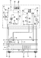
- FIG. 1 is a configuration diagram illustrating an example of an elevator system according to the first embodiment.
- the elevator system includes a hoist 1, a main rope 2, a car 3, a counterweight 4, and a control panel 5.
- the main rope 2 is wound around the hoist 1.
- the car 3 and the counterweight 4 are suspended in a hoistway (not shown) by the main rope 2.
- the hoistway is formed, for example, so as to penetrate each floor of a building (not shown).
- the elevator car 3 and the counterweight 4 are lifted and lowered when the hoist 1 is driven.
- the control panel 5 has a function of controlling the hoisting machine 1.
- a pair of car guide rails 6, a pair of weight guide rails 7, and conductive wires 8 are provided in the hoistway.
- the car guide rail 6 and the weight guide rail 7 are provided vertically, for example.
- the car guide rail 6 guides the raising and lowering of the car 3.
- the weight guide rail 7 guides the lifting and lowering of the counterweight 4.
- the conductive wire 8 is provided in parallel along the longitudinal direction of the weight guide rail 7.
- a limit switch is attached to the guide rail 6 for the car.
- the limit switch is provided in the upper part and the lower part of the hoistway.
- the limit switch is arranged near the terminal floor.
- the limit switch includes an upper limit switch 9 and a lower limit switch 10.
- the upper limit switch 9 is disposed at a position where the upper limit switch 9 operates when the car 3 goes over the top floor in the upper part of the hoistway.
- the lower limit switch 10 is disposed at a position that operates when the car 3 goes over the lowest floor in the lower part of the hoistway.
- the limit switch is electrically connected to the control panel 5.
- a contact 12 is attached to the frame of the counterweight 4 via a support 11.
- the contact 12 is formed in a cylindrical shape, for example.
- the upper surface and the lower surface of the contact 12 are formed horizontally.
- the contact 12 is provided so as to surround the conductive wire 8 when viewed from above and below. That is, the conductive wire 8 is in a state of passing through the contact 12.
- the contact 12 is disposed at a position that does not contact the conductive wire 8 in a normal state.
- the contact 12 is disposed at a position where it comes into contact with the conductive wire 8 when the counterweight 4 comes off the weight guide rail 7.
- the shape of the contact 12 viewed from the up-down direction may be circular or polygonal.
- At least the surfaces of the main rope 2, the frame of the counterweight 4, the conductive wire 8, the support 11 and the contact 12 are formed of a conductive member. That is, the contact 12 is electrically connected to the hoist 1 through the support 11, the frame of the counterweight 4, and the main rope 2.
- a contact for detecting overshoot is attached to the conductive wire 8.
- the overshoot detecting contact is formed in a cylindrical shape similar to that of the contact 12, for example.
- the overshoot detection contact includes an upper overshoot detection contact 13 and a lower overshoot detection contact 14.
- the upper overshoot detecting contact 13 is disposed above the upper limit switch 9 in the hoistway.
- the upper overshoot detecting contact 13 is disposed above the contact 12 when the car 3 is stopped on the lowest floor.
- the lower overshoot detecting contact 14 is disposed below the lower limit switch 10 in the hoistway.
- the lower overshoot detection contact 14 is disposed below the contact 12 when the car 3 is stopped on the top floor.
- the conductive wire 8 is electrically connected to the control panel 5.
- the conductive wire 8 is electrically connected to the control panel 5 so as to be energized from the control panel 5 over a range through which the contact 12 can pass.
- the connection position of the conductive wire 8 with the control panel 5 is, for example, both a position above the upper overshoot detection contact 13 and a position below the lower overshoot detection contact 14.
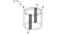
- FIG. 2 is a perspective view showing an example of a contact for detecting overshoot in the first embodiment.
- the overshoot detecting contact has a first conductive portion 29, a second conductive portion 30, and an insulating portion 31.
- the first conductive part 29 and the second conductive part 30 are made of a conductive material.
- the insulating portion 31 is an insulator that separates the first conductive portion 29 and the second conductive portion 30.
- the insulating portion 31 is disposed along a surface that bisects the overshoot detecting contact member in the left and right directions.
- the overshoot detection contact has, for example, an upper surface and a lower surface that are formed horizontally. That is, when the contact 12 comes into contact with the overshoot detection contact from above or below, the contact 12 contacts both the first conductive portion 29 and the second conductive portion 30 simultaneously.
- the first conductive portion 29 is fixed in contact with the conductive wire 8 in the state shown in FIG. In the state shown in FIG. 1, the second conductive portion 30 does not contact the conductive wire 8 and is electrically connected to the control panel 5. In other words, the first conductive portion 29 is not electrically connected to the second conductive portion 30 except when passing through another conductive object.
- the control panel 5 includes a power supply device 15, an input / output board 16, and a safety circuit 17.
- the input / output board 16 includes a control unit 16a.
- the control panel 5 has a relay DR and a relay FL.
- the relay DR has a coil 18, an a contact 19, an a contact 20 and an a contact 21.
- the relay FL has a coil 22, a b contact 23, a b contact 24, a b contact 25 and a b contact 26.
- the a contact 19 of the relay DR and the b contact 23 of the relay FL are provided between the power supply device 15 and the conductive wire 8.
- the control panel 5 includes a derailing detector 27 and an overshoot detector 28.
- the rail release detection unit 27 includes a portion that receives a signal among the coil 18 of the relay DR, the a contact 20 of the relay DR, the b contact 24 of the relay FL, and the input / output board 16.
- the overshoot detection unit 28 includes an a contact 21 of the relay DR, a coil 22 of the relay FL, a b contact 25 of the relay FL, and a b contact 26 of the relay FL.
- portions corresponding to the power supply device 15, the conductive wire 8, the contact 12, the support body 11, the counterweight 4, the main rope 2, the hoisting machine 1, and the rail release detection unit 27 are removed.
- the rail detection circuit Works as a rail detection circuit.
- the b-contact 23 of the relay FL When the elevator is operating normally, the b-contact 23 of the relay FL is in a closed state, so that the conductive wire 8 is in an energized state. In this case, since the voltage is applied to the coil 18 of the relay DR, the a contact 19, the a contact 20, and the a contact 21 are closed. When the a contact 20 is in the closed state, the rail release detection signal DR is input to the input / output board 16.
- the input of the rail release detection signal DR to the input / output board 16 is also expressed as “the rail release detection signal DR is detected by the rail release detection unit 27”.
- the power supply device 15 When the contact 12 comes into contact with the conductive wire 8 due to the rail of the counterweight 4 being removed, the power supply device 15 winds the conductive wire 8, the contact 12, the support 11, the frame of the counterweight 4 and the main rope 2. A current flows to the upper machine 1. That is, when the contact 12 comes into contact with the conductive wire 8, a ground fault occurs. In this case, the power supply device 15 cuts off the power supply to the derailing detection circuit by operating the overcurrent protection function. As a result, no voltage is applied to the coil 18 of the relay DR, and the contact a 20 is opened. In other words, when the conductive wire 8 and the contact 12 are brought into conduction, the rail removal detection unit 27 does not detect the rail removal detection signal DR. As described above, the rail removal detection unit 27 detects the rail removal of the counterweight 4 based on the fact that the rail removal detection signal DR is not detected.
- the control unit 16a stops the car 3 suddenly. That is, the control part 16a will stop the cage
- stopping the car 3 based on the detection of the continuity between the conductive wire 8 and the contact 12 by the rail-removal detection unit 27 is also referred to as “first stop operation”.
- the upper limit switch 9 is electrically connected to the power supply device 15 and the safety circuit 17.
- the lower limit switch 10 is electrically connected to the power supply device 15 and the safety circuit 17.
- the limit switch operates, for example, by contacting a cam provided on the side surface of the car 3.
- an electric signal is input from the limit switch to the safety circuit 17.
- the limit switch is operated, an electric signal is not input to the safety circuit 17 from the limit switch.
- the control unit 16a decelerates the car 3. That is, the control unit 16a decelerates the car 3 when the car 3 goes over the terminal floor.
- the upper overshoot detection contact 13 and the lower overshoot detection contact 14 are electrically connected to an overshoot detection unit 28.
- the contact 12 does not contact the overshoot detection contact. Further, even when the limit switch is operated, the contact 12 does not contact the overshoot detecting contact.
- the first conductive portion 29 is in an energized state
- the second conductive portion 30 is not in an energized state.
- no voltage is applied to the coil 22 of the relay FL, so the b contact 25 and the b contact 26 are closed.
- an electrical signal is input to the safety circuit 17 from the b contact 25 and the b contact 26.
- the input of an electrical signal from the b contact 25 and the b contact 26 to the safety circuit 17 is also expressed as “the electrical signal is detected by the overshoot detection unit 28”.
- the contact 12 contacts the lower overshoot detection contact 14.
- the contact 12 comes into contact with the upper overshoot detection contact 13.
- the first conductive portion 29 and the second conductive portion 30 are electrically connected via the contact 12.
- a voltage is applied to the coil 22 of the relay FL, so that the b contact 25 and the b contact 26 are opened. That is, when the contact 12 contacts the overshoot detection contact, the overshoot detection unit 28 does not detect an electrical signal. In this manner, the overshoot detection unit 28 detects that the car 3 has exceeded the position where the limit switch operates based on the fact that the electrical signal is no longer detected by the overshoot detection unit 28.
- the control unit 16a When the electric signal is no longer detected by the overshoot detection unit 28, the control unit 16a suddenly stops the car 3. That is, when the contact between the contact 12 and the overshoot detection contact is detected, the control unit 16a stops the car 3 suddenly.
- stopping the car 3 based on the detection that the contact 12 has contacted the over-detection contact by the over-travel detection unit 28 is also referred to as “second stop operation”.
- the power supply device 15 passes through the conductive wire 8, the first conductive portion 29, the contact 12, the support 11, the frame of the counterweight 4, and the main rope 2. Current flows to the hoist 1. That is, an energized state similar to that when the counterweight 4 is removed is created in a pseudo manner. For this reason, when the contact 12 contacts the contact for detecting overshoot, not only the “second stop operation” but also the “first stop operation” is performed.
- FIG. 3 is a flowchart showing an operation example of the elevator system according to the first embodiment.
- step S101 When the elevator is operating normally (step S101), the derailment detection circuit is in a live state (step S102).
- step S102 When the elevator is operating normally, the first conductive part 29 of the overshoot detecting contact is in a live line state, and the second conductive part 30 is in a non-live line state (step S103).
- step S104 The operation of the elevator system differs depending on whether or not the counterweight 4 has been removed from the rail.
- step S104 the control unit 16a performs the first stop operation (step S105).
- step S105 The car 3 is suddenly stopped by the process of step S105 (step S106).
- step S104 If the counterweight 4 is not derailed in step S104, the operation of the elevator system differs depending on whether the car 3 has passed the terminal floor (step S107). If the car 3 has not passed the terminal floor in step S107, the determination in step S104 is performed.
- step S107 when the car 3 has passed the final floor, the car 3 is decelerated by the operation of the limit switch (step S108).
- the operation after step S108 differs depending on whether or not the car 3 has gone beyond the position where the limit switch operates (step S109). If the car 3 does not go too far beyond the position where the limit switch operates in step S109, the determination in step S104 is performed.
- Step S109 when the car 3 goes too far beyond the position where the limit switch operates, the contact 12 comes into contact with the overshoot detection contact (Step S110). In this case, the control unit 16a performs the first stop operation and the second stop operation (step S111). The car 3 is suddenly stopped by the process of step S111 (step S106).
- one of the limit switches is provided in the upper part or the lower part of the hoistway.
- the limit switch operates when the car 3 has passed the terminal floor.
- the conductive wire 8 is provided along a guide rail that guides the movement of the counterweight 4.
- the contact 12 attached to the counterweight 4 is disposed at a position where it comes into contact with the conductive wire 8 when the counterweight 4 comes off the guide rail.
- One of the overshoot detection contacts is attached to the conductive wire 8 on the opposite side of the upper or lower part of the hoistway from the limit switch.
- the overshoot detecting contact is arranged at a position where it does not come into contact with the contact 12 when the limit switch is operated, and comes into contact with the contact 12 when the car 3 moves beyond the position where the limit switch operates. Yes.
- the overshoot detection unit 28 detects that the contact 12 has come into contact with the overshoot detection contact. For this reason, according to the first embodiment, it is possible to detect that the car has gone beyond the position where the limit switch
- the first conductive portion 29 of the contact for detecting overshoot is in contact with the conductive wire 8.
- the second conductive portion 30 of the overshoot detecting contact is not in contact with the conductive wire 8 and is connected to the overshoot detecting portion 28.
- the insulating portion 31 of the contact for detecting overshoot separates the first conductive portion 29 and the second conductive portion 30.
- the overshoot detecting contact is formed in a shape in which both the first conductive portion 29 and the second conductive portion 30 are simultaneously in contact with the contact 12 when the car 3 moves beyond the position where the limit switch operates. .
- the overshoot detecting contact is formed so as to electrically connect the conductive wire 8 and the overshoot detecting unit 28 only when contacting the contact 12. For this reason, according to the first embodiment, it is possible to detect that the car has gone beyond the position where the limit switch operates.
- the rail removal detection unit 27 detects conduction between the conductive wire 8 and the contact 12.
- the control panel 5 performs a first stop operation for stopping the car 3 based on the detection of the continuity between the conductive wire 8 and the contact 12 by the rail removal detector 27.
- the control panel 5 performs a second stop operation for stopping the car based on the fact that the overshoot detecting unit 28 detects that the contact 12 has contacted the overshoot detecting contact. That is, when the contact 12 comes into contact with the overshoot detection contact, the control panel 5 performs both the first stop operation and the second stop operation. For this reason, according to the first embodiment, when the car goes too far beyond the position where the limit switch operates, the derailing detection circuit can function as fault tolerance.
- the conductive wire 8, the contact 12, the upper overshoot detection contact 13 and the lower overshoot detection contact 14 may be provided for each weight guide rail 7. That is, the conductive wire 8, the contact 12, the upper overshoot detection contact 13, and the lower overshoot detection contact 14 may be provided, for example, two each. Even in this case, overshoot of the car can be detected by the same method.
- FIG. 4 is a hardware configuration diagram of the control panel.
- the processing circuit may be dedicated hardware 50.
- the processing circuit may include a processor 51 and a memory 52.
- a part of the processing circuit is formed as dedicated hardware 50, and may further include a processor 51 and a memory 52.
- FIG. 4 shows an example in which the processing circuit is partly formed as dedicated hardware 50 and includes a processor 51 and a memory 52.
- the processing circuit may be, for example, a single circuit, a composite circuit, a programmed processor, a parallel programmed processor, an ASIC, an FPGA, or the like. The combination is applicable.
- each function of the control unit 16a and the safety circuit 17 is realized by software, firmware, or a combination of software and firmware.
- Software and firmware are described as programs and stored in the memory 52.
- the processor 51 reads out and executes the program stored in the memory 52, thereby realizing the function of each unit.
- the processor 51 is also referred to as a CPU (Central Processing Unit), a central processing unit, a processing unit, an arithmetic unit, a microprocessor, a microcomputer, and a DSP.
- the memory 52 corresponds to, for example, a nonvolatile or volatile semiconductor memory such as a RAM, a ROM, a flash memory, an EPROM, and an EEPROM, a magnetic disk, a flexible disk, an optical disk, a compact disk, a mini disk, and a DVD.
- a nonvolatile or volatile semiconductor memory such as a RAM, a ROM, a flash memory, an EPROM, and an EEPROM, a magnetic disk, a flexible disk, an optical disk, a compact disk, a mini disk, and a DVD.
- the processing circuit can realize each function of the control panel 5 by hardware, software, firmware, or a combination thereof.
- the present invention can be applied to an elevator.
Landscapes
- Engineering & Computer Science (AREA)
- Automation & Control Theory (AREA)
- Life Sciences & Earth Sciences (AREA)
- Environmental & Geological Engineering (AREA)
- General Life Sciences & Earth Sciences (AREA)
- Geology (AREA)
- Remote Sensing (AREA)
- Mechanical Engineering (AREA)
- Computer Networks & Wireless Communication (AREA)
- Maintenance And Inspection Apparatuses For Elevators (AREA)
- Elevator Control (AREA)
Abstract
L'invention concerne un système d'ascenseur qui peut détecter le moment où une cabine d'ascenseur accomplit un dépassement et va au-delà de la position de fonctionnement d'un interrupteur de fin de course. Ce système d'ascenseur comprend: un interrupteur de fin de course disposé dans la partie supérieure ou inférieure d'une cage et entrant en action lorsqu'une cabine d'ascenseur (3) dépasse un plancher d'arrivée; un câble de guidage (8) disposé le long du rail de guidage (5) pour guider le mouvement d'un contrepoids (4); un contact (12) de guidage fixé au contrepoids (4), et qui vient au contact du câble de guidage (8) si le contrepoids (4) s'éloigne du rail de guidage; un contact de détection de dépassement qui est conducteur, est fixé au câble de guidage (8) dans celle de la partie supérieure ou inférieure de la cage qui est le côté opposé à l'interrupteur de fin de course, et est disposé dans une position telle qu'il vient en contact avec le contact (12) si la cabine d'ascenseur (3) se déplace au-delà de la position de fonctionnement de l'interrupteur de fin de course; et une unité de détection de dépassement (28) disposée dans un tableau de commande (5) raccordé électriquement au câble de guidage (8) et qui détecte le moment où le contact (12) vient en contact avec le contact de détection de dépassement.
Priority Applications (4)
| Application Number | Priority Date | Filing Date | Title |
|---|---|---|---|
| JP2018517963A JP6593530B2 (ja) | 2016-05-17 | 2016-05-17 | エレベータシステム |
| PCT/JP2016/064581 WO2017199329A1 (fr) | 2016-05-17 | 2016-05-17 | Système d'ascenseur |
| US16/092,616 US11279592B2 (en) | 2016-05-17 | 2016-05-17 | Elevator system |
| TW105127020A TWI586603B (zh) | 2016-05-17 | 2016-08-24 | 昇降機系統 |
Applications Claiming Priority (1)
| Application Number | Priority Date | Filing Date | Title |
|---|---|---|---|
| PCT/JP2016/064581 WO2017199329A1 (fr) | 2016-05-17 | 2016-05-17 | Système d'ascenseur |
Publications (1)
| Publication Number | Publication Date |
|---|---|
| WO2017199329A1 true WO2017199329A1 (fr) | 2017-11-23 |
Family
ID=59688177
Family Applications (1)
| Application Number | Title | Priority Date | Filing Date |
|---|---|---|---|
| PCT/JP2016/064581 Ceased WO2017199329A1 (fr) | 2016-05-17 | 2016-05-17 | Système d'ascenseur |
Country Status (4)
| Country | Link |
|---|---|
| US (1) | US11279592B2 (fr) |
| JP (1) | JP6593530B2 (fr) |
| TW (1) | TWI586603B (fr) |
| WO (1) | WO2017199329A1 (fr) |
Families Citing this family (2)
| Publication number | Priority date | Publication date | Assignee | Title |
|---|---|---|---|---|
| WO2017199329A1 (fr) * | 2016-05-17 | 2017-11-23 | 三菱電機株式会社 | Système d'ascenseur |
| JP7848606B2 (ja) * | 2022-06-17 | 2026-04-21 | 三菱電機株式会社 | 昇降体の脱レール検出装置 |
Citations (3)
| Publication number | Priority date | Publication date | Assignee | Title |
|---|---|---|---|---|
| JPS5762177A (en) * | 1980-09-26 | 1982-04-15 | Mitsubishi Electric Corp | Detector for derailment of elevator |
| JPH0380084U (fr) * | 1989-08-18 | 1991-08-15 | ||
| JP2002167133A (ja) * | 2000-11-29 | 2002-06-11 | Toshiba Corp | エレベータの位置検出装置 |
Family Cites Families (12)
| Publication number | Priority date | Publication date | Assignee | Title |
|---|---|---|---|---|
| JPH05262473A (ja) | 1992-03-19 | 1993-10-12 | Hitachi Ltd | エレベータの端階安全装置 |
| JP4107728B2 (ja) * | 1998-09-07 | 2008-06-25 | 東芝エレベータ株式会社 | エレベータ装置 |
| EP1151953A1 (fr) * | 2000-04-27 | 2001-11-07 | Inventio Ag | Dispositif d'évacuation des passagers d'un ascenseur |
| US7641024B2 (en) * | 2006-05-17 | 2010-01-05 | Bauge Harry G | Operating residential elevator |
| JP2012180132A (ja) * | 2009-06-29 | 2012-09-20 | Mitsubishi Electric Corp | エレベータ装置 |
| JPWO2011010376A1 (ja) | 2009-07-23 | 2012-12-27 | 三菱電機株式会社 | エレベータの脱レール検出装置 |
| JP5529075B2 (ja) * | 2011-05-25 | 2014-06-25 | 株式会社日立製作所 | エレベータ |
| FR2977881B1 (fr) * | 2011-07-13 | 2015-08-21 | Arnoult Patrice | Dispositif de blocage de cabine d'ascenseur dans une gaine a une distance determinee du plafond ou du sol de la gaine |
| JP5526092B2 (ja) * | 2011-09-06 | 2014-06-18 | 株式会社日立製作所 | 電子化エレベータ |
| BR112014012859B1 (pt) * | 2011-11-29 | 2021-07-13 | Inventio Ag | Processo para o reposicionamento de um freio de segurança e dispositivo de segurança em um sistema de elevador |
| US10745243B2 (en) * | 2014-10-21 | 2020-08-18 | Inventio Ag | Elevator comprising a decentralized electronic safety system |
| WO2017199329A1 (fr) * | 2016-05-17 | 2017-11-23 | 三菱電機株式会社 | Système d'ascenseur |
-
2016
- 2016-05-17 WO PCT/JP2016/064581 patent/WO2017199329A1/fr not_active Ceased
- 2016-05-17 JP JP2018517963A patent/JP6593530B2/ja not_active Expired - Fee Related
- 2016-05-17 US US16/092,616 patent/US11279592B2/en not_active Expired - Fee Related
- 2016-08-24 TW TW105127020A patent/TWI586603B/zh not_active IP Right Cessation
Patent Citations (3)
| Publication number | Priority date | Publication date | Assignee | Title |
|---|---|---|---|---|
| JPS5762177A (en) * | 1980-09-26 | 1982-04-15 | Mitsubishi Electric Corp | Detector for derailment of elevator |
| JPH0380084U (fr) * | 1989-08-18 | 1991-08-15 | ||
| JP2002167133A (ja) * | 2000-11-29 | 2002-06-11 | Toshiba Corp | エレベータの位置検出装置 |
Also Published As
| Publication number | Publication date |
|---|---|
| US11279592B2 (en) | 2022-03-22 |
| TWI586603B (zh) | 2017-06-11 |
| JPWO2017199329A1 (ja) | 2018-11-29 |
| TW201741222A (zh) | 2017-12-01 |
| JP6593530B2 (ja) | 2019-10-23 |
| US20190119069A1 (en) | 2019-04-25 |
Similar Documents
| Publication | Publication Date | Title |
|---|---|---|
| JP4994837B2 (ja) | エレベータ装置 | |
| CN100542929C (zh) | 电梯装置 | |
| CN1795137B (zh) | 电梯的紧急停止装置 | |
| JP4641306B2 (ja) | エレベータのレール継ぎ目検出装置、及びエレベータ装置 | |
| JP7212201B2 (ja) | エレベータ装置 | |
| JP6579267B2 (ja) | エレベータシステム | |
| JP6593530B2 (ja) | エレベータシステム | |
| CN1795133B (zh) | 电梯控制装置 | |
| JP4292203B2 (ja) | エレベータ装置 | |
| WO2017183084A1 (fr) | Dispositif de détection de déraillement d'ascenseur | |
| JP6697793B2 (ja) | エレベータの釣合おもりの脱レール検出装置 | |
| JP4292204B2 (ja) | エレベータ装置 | |
| JP6698942B2 (ja) | エレベータの脱レール検出装置 | |
| CN111867957B (zh) | 电梯脱轨检测装置 | |
| US12054358B2 (en) | Guide deviation detection device for elevators | |
| KR100807934B1 (ko) | 엘리베이터 장치 | |
| JP2017088318A (ja) | ブレーキ制動力測定装置 | |
| JPH0567557B2 (fr) | ||
| KR20060081720A (ko) | 엘리베이터 제어 장치 |
Legal Events
| Date | Code | Title | Description |
|---|---|---|---|
| WWE | Wipo information: entry into national phase |
Ref document number: 2018517963 Country of ref document: JP |
|
| NENP | Non-entry into the national phase |
Ref country code: DE |
|
| 121 | Ep: the epo has been informed by wipo that ep was designated in this application |
Ref document number: 16902349 Country of ref document: EP Kind code of ref document: A1 |
|
| 122 | Ep: pct application non-entry in european phase |
Ref document number: 16902349 Country of ref document: EP Kind code of ref document: A1 |