WO2017199333A1 - 情報出力装置、端末装置、制御方法、プログラム及び記憶媒体 - Google Patents
情報出力装置、端末装置、制御方法、プログラム及び記憶媒体 Download PDFInfo
- Publication number
- WO2017199333A1 WO2017199333A1 PCT/JP2016/064598 JP2016064598W WO2017199333A1 WO 2017199333 A1 WO2017199333 A1 WO 2017199333A1 JP 2016064598 W JP2016064598 W JP 2016064598W WO 2017199333 A1 WO2017199333 A1 WO 2017199333A1
- Authority
- WO
- WIPO (PCT)
- Prior art keywords
- information
- unit
- feature
- point group
- output
- Prior art date
- Legal status (The legal status is an assumption and is not a legal conclusion. Google has not performed a legal analysis and makes no representation as to the accuracy of the status listed.)
- Ceased
Links
Images




Classifications
-
- G—PHYSICS
- G01—MEASURING; TESTING
- G01C—MEASURING DISTANCES, LEVELS OR BEARINGS; SURVEYING; NAVIGATION; GYROSCOPIC INSTRUMENTS; PHOTOGRAMMETRY OR VIDEOGRAMMETRY
- G01C21/00—Navigation; Navigational instruments not provided for in groups G01C1/00 - G01C19/00
- G01C21/26—Navigation; Navigational instruments not provided for in groups G01C1/00 - G01C19/00 specially adapted for navigation in a road network
- G01C21/28—Navigation; Navigational instruments not provided for in groups G01C1/00 - G01C19/00 specially adapted for navigation in a road network with correlation of data from several navigational instruments
-
- G—PHYSICS
- G01—MEASURING; TESTING
- G01C—MEASURING DISTANCES, LEVELS OR BEARINGS; SURVEYING; NAVIGATION; GYROSCOPIC INSTRUMENTS; PHOTOGRAMMETRY OR VIDEOGRAMMETRY
- G01C21/00—Navigation; Navigational instruments not provided for in groups G01C1/00 - G01C19/00
- G01C21/005—Navigation; Navigational instruments not provided for in groups G01C1/00 - G01C19/00 with correlation of navigation data from several sources, e.g. map or contour matching
-
- G—PHYSICS
- G01—MEASURING; TESTING
- G01S—RADIO DIRECTION-FINDING; RADIO NAVIGATION; DETERMINING DISTANCE OR VELOCITY BY USE OF RADIO WAVES; LOCATING OR PRESENCE-DETECTING BY USE OF THE REFLECTION OR RERADIATION OF RADIO WAVES; ANALOGOUS ARRANGEMENTS USING OTHER WAVES
- G01S13/00—Systems using the reflection or reradiation of radio waves, e.g. radar systems; Analogous systems using reflection or reradiation of waves whose nature or wavelength is irrelevant or unspecified
- G01S13/88—Radar or analogous systems specially adapted for specific applications
- G01S13/93—Radar or analogous systems specially adapted for specific applications for anti-collision purposes
- G01S13/931—Radar or analogous systems specially adapted for specific applications for anti-collision purposes of land vehicles
-
- G—PHYSICS
- G01—MEASURING; TESTING
- G01S—RADIO DIRECTION-FINDING; RADIO NAVIGATION; DETERMINING DISTANCE OR VELOCITY BY USE OF RADIO WAVES; LOCATING OR PRESENCE-DETECTING BY USE OF THE REFLECTION OR RERADIATION OF RADIO WAVES; ANALOGOUS ARRANGEMENTS USING OTHER WAVES
- G01S17/00—Systems using the reflection or reradiation of electromagnetic waves other than radio waves, e.g. lidar systems
- G01S17/86—Combinations of lidar systems with systems other than lidar, radar or sonar, e.g. with direction finders
-
- G—PHYSICS
- G01—MEASURING; TESTING
- G01S—RADIO DIRECTION-FINDING; RADIO NAVIGATION; DETERMINING DISTANCE OR VELOCITY BY USE OF RADIO WAVES; LOCATING OR PRESENCE-DETECTING BY USE OF THE REFLECTION OR RERADIATION OF RADIO WAVES; ANALOGOUS ARRANGEMENTS USING OTHER WAVES
- G01S17/00—Systems using the reflection or reradiation of electromagnetic waves other than radio waves, e.g. lidar systems
- G01S17/88—Lidar systems specially adapted for specific applications
- G01S17/89—Lidar systems specially adapted for specific applications for mapping or imaging
-
- G—PHYSICS
- G01—MEASURING; TESTING
- G01S—RADIO DIRECTION-FINDING; RADIO NAVIGATION; DETERMINING DISTANCE OR VELOCITY BY USE OF RADIO WAVES; LOCATING OR PRESENCE-DETECTING BY USE OF THE REFLECTION OR RERADIATION OF RADIO WAVES; ANALOGOUS ARRANGEMENTS USING OTHER WAVES
- G01S17/00—Systems using the reflection or reradiation of electromagnetic waves other than radio waves, e.g. lidar systems
- G01S17/88—Lidar systems specially adapted for specific applications
- G01S17/93—Lidar systems specially adapted for specific applications for anti-collision purposes
- G01S17/931—Lidar systems specially adapted for specific applications for anti-collision purposes of land vehicles
-
- G—PHYSICS
- G01—MEASURING; TESTING
- G01S—RADIO DIRECTION-FINDING; RADIO NAVIGATION; DETERMINING DISTANCE OR VELOCITY BY USE OF RADIO WAVES; LOCATING OR PRESENCE-DETECTING BY USE OF THE REFLECTION OR RERADIATION OF RADIO WAVES; ANALOGOUS ARRANGEMENTS USING OTHER WAVES
- G01S7/00—Details of systems according to groups G01S13/00, G01S15/00, G01S17/00
- G01S7/003—Transmission of data between radar, sonar or lidar systems and remote stations
-
- G—PHYSICS
- G06—COMPUTING OR CALCULATING; COUNTING
- G06V—IMAGE OR VIDEO RECOGNITION OR UNDERSTANDING
- G06V20/00—Scenes; Scene-specific elements
- G06V20/50—Context or environment of the image
- G06V20/56—Context or environment of the image exterior to a vehicle by using sensors mounted on the vehicle
- G06V20/58—Recognition of moving objects or obstacles, e.g. vehicles or pedestrians; Recognition of traffic objects, e.g. traffic signs, traffic lights or roads
-
- G—PHYSICS
- G01—MEASURING; TESTING
- G01S—RADIO DIRECTION-FINDING; RADIO NAVIGATION; DETERMINING DISTANCE OR VELOCITY BY USE OF RADIO WAVES; LOCATING OR PRESENCE-DETECTING BY USE OF THE REFLECTION OR RERADIATION OF RADIO WAVES; ANALOGOUS ARRANGEMENTS USING OTHER WAVES
- G01S13/00—Systems using the reflection or reradiation of radio waves, e.g. radar systems; Analogous systems using reflection or reradiation of waves whose nature or wavelength is irrelevant or unspecified
- G01S13/88—Radar or analogous systems specially adapted for specific applications
- G01S13/93—Radar or analogous systems specially adapted for specific applications for anti-collision purposes
- G01S13/931—Radar or analogous systems specially adapted for specific applications for anti-collision purposes of land vehicles
- G01S2013/9316—Radar or analogous systems specially adapted for specific applications for anti-collision purposes of land vehicles combined with communication equipment with other vehicles or with base stations
-
- G—PHYSICS
- G01—MEASURING; TESTING
- G01S—RADIO DIRECTION-FINDING; RADIO NAVIGATION; DETERMINING DISTANCE OR VELOCITY BY USE OF RADIO WAVES; LOCATING OR PRESENCE-DETECTING BY USE OF THE REFLECTION OR RERADIATION OF RADIO WAVES; ANALOGOUS ARRANGEMENTS USING OTHER WAVES
- G01S13/00—Systems using the reflection or reradiation of radio waves, e.g. radar systems; Analogous systems using reflection or reradiation of waves whose nature or wavelength is irrelevant or unspecified
- G01S13/88—Radar or analogous systems specially adapted for specific applications
- G01S13/93—Radar or analogous systems specially adapted for specific applications for anti-collision purposes
- G01S13/931—Radar or analogous systems specially adapted for specific applications for anti-collision purposes of land vehicles
- G01S2013/9322—Radar or analogous systems specially adapted for specific applications for anti-collision purposes of land vehicles using additional data, e.g. driver condition, road state or weather data
-
- G—PHYSICS
- G01—MEASURING; TESTING
- G01S—RADIO DIRECTION-FINDING; RADIO NAVIGATION; DETERMINING DISTANCE OR VELOCITY BY USE OF RADIO WAVES; LOCATING OR PRESENCE-DETECTING BY USE OF THE REFLECTION OR RERADIATION OF RADIO WAVES; ANALOGOUS ARRANGEMENTS USING OTHER WAVES
- G01S13/00—Systems using the reflection or reradiation of radio waves, e.g. radar systems; Analogous systems using reflection or reradiation of waves whose nature or wavelength is irrelevant or unspecified
- G01S13/88—Radar or analogous systems specially adapted for specific applications
- G01S13/93—Radar or analogous systems specially adapted for specific applications for anti-collision purposes
- G01S13/931—Radar or analogous systems specially adapted for specific applications for anti-collision purposes of land vehicles
- G01S2013/9323—Alternative operation using light waves
Definitions
- the present invention relates to a technology for outputting information.
- Patent Document 1 discloses a technique for estimating a self-position by matching an observation result of an external sensor that observes landmarks around a moving body and a global map that contains information about landmarks in the entire environment. Is disclosed.
- the present invention has been made in order to solve the above-described problems, for example, and has as its main object to provide an information output device capable of suitably reducing the amount of data to be output.
- the invention described in the claims is an information output device, and an acquisition unit that acquires characteristic information about characteristics of an external field detection device arranged on a moving body, and a ground that is stored in a storage unit based on the characteristic information.
- An output unit that extracts and outputs a part of the feature information from the feature information indicating the object.
- the invention described in the claims is a terminal device that moves together with a moving body in which an external field detection device is arranged, and includes a storage unit that stores characteristic information related to characteristics of the external field detection device, and the characteristic information.
- a transmission unit that transmits to the information output device according to any one of 1 to 4, a reception unit that receives feature information from the information output device, the feature information, and detection information of the external field detection device, And an estimation unit for estimating the current position based on.
- the invention described in the claims is a control method executed by the information output device, based on the acquisition step of acquiring characteristic information about the characteristic of the external field detection device arranged on the moving body, and the characteristic information, And an output step of extracting and outputting a part of the feature information from the feature information indicating the feature stored in the storage unit.
- the invention described in the claims is a program executed by a computer, and an acquisition unit that acquires characteristic information about characteristics of an external field detection device arranged in a moving body, and a storage unit based on the characteristic information
- the computer is caused to function as an output unit that extracts and outputs a part of the feature information from the feature information indicating the stored feature.
- FIG. 1 It is a schematic structure of an advanced map system.
- A A schematic configuration of the in-vehicle device is shown.
- B shows the data structure of rider characteristic information.
- 1 shows a schematic configuration of a server device. It is a block diagram which shows the functional structure of a vehicle equipment.
- A It is the figure which showed a mode that the laser output from a lidar was irradiated to features, such as a building in the vehicle equipment periphery.
- B It is the figure which extracted the point cloud used as the irradiation position of a laser.
- A It is the figure which visualized the point cloud around the own vehicle position registered into three-dimensional point cloud DB.
- B It is the figure which extracted the point cloud corresponding to map point cloud information. It is a flowchart which shows the procedure of the own vehicle position estimation process which concerns on an Example.
- the information output device is an acquisition unit that acquires characteristic information relating to characteristics of an external field detection device arranged on a moving body, and stores in the storage unit based on the characteristic information.
- An output unit that extracts and outputs a part of the feature information from the feature information indicating the feature that has been generated.
- extracting part of the feature information refers to extracting a part of the feature information from the feature information stored in the storage unit based on the characteristic information. Therefore, when the feature information for each of the predetermined number of features is stored in the storage unit, the feature information for the feature corresponding to the whole is extracted as it is, or the feature for the feature to which a part is applicable. The aspect which cuts out and extracts the applicable part of physical information is also contained.
- the information output device can suitably limit the feature information to be output based on the characteristic information related to the characteristics of the external field detection device.
- the output unit specifies a detection range of the external field detection device based on the characteristic information, and extracts and outputs feature information of features existing in the detection range.
- the information output device can preferably output the feature information within the detection range of the external detection device, and can be used for matching with the detection information of the external detection device.
- the characteristic information relates to information related to a height of an installation position of the external environment detection device, or a range in which the external environment detection device performs detection in the horizontal direction and / or the vertical direction. Contains information.
- the information output device can preferably specify the detection range of the external detection device and determine the feature information to be extracted.
- the acquisition unit receives the characteristic information and the position information of the moving body from a terminal device that receives detection information of the external environment detection device, and the output unit receives the characteristic The feature information extracted based on the information and the position information is transmitted to the terminal device.
- the information output device can cause the terminal device to suitably acquire the detection information of the external environment detection device and the feature information corresponding to the detection information.
- a terminal device that moves together with a mobile object in which an external field detection device is arranged, a storage unit that stores characteristic information relating to characteristics of the external field detection device, and the characteristic information Based on the transmission unit that transmits the information to the information output device, the reception unit that receives the feature information from the information output device, the feature information, and the detection information of the external field detection device.
- An estimation unit for estimation the terminal device can receive the minimum feature information necessary for estimating the current position from the information output device that stores the feature information, and can efficiently estimate the current position.
- the detection information and the feature information are point cloud information
- the estimation unit indicates the point cloud indicated by the detection information and the feature information corresponding to the point cloud.
- the current position is estimated based on a position error with respect to the point cloud.
- the terminal device can accurately estimate its own position from the point cloud information output by the external field detection device with reference to the point cloud information of the feature stored in advance by the information output device.
- the terminal device further includes a position prediction unit that obtains a predicted value of the current position based on the output of the measurement unit, and the estimation unit includes the feature information and the detection information.
- the estimated value of the current position is calculated by correcting the predicted value based on the calculated value. According to this aspect, the terminal device can acquire the current position with higher accuracy than the current position measured by the measurement unit.
- a control method executed by the information output device the acquisition step of acquiring characteristic information related to the characteristics of the external field detection device arranged on the moving body, and the characteristic information And an output step for extracting and outputting a part of the feature information from the feature information indicating the feature stored in the storage unit.
- the information output device can suitably limit the feature information to be output based on the characteristic information related to the characteristics of the external environment detection device.
- a program executed by a computer based on the acquisition unit that acquires characteristic information about the characteristic of the external field detection device arranged in the moving body, and the characteristic information
- the computer is caused to function as an output unit that extracts and outputs a part of the feature information from the feature information indicating the feature stored in the storage unit.
- the computer can suitably limit the feature information to be output based on the characteristic information relating to the characteristics of the external detection device.
- the program is stored in a storage medium.
- the point group refers to an aggregate of points whose three-dimensional positions are specified, and the three-dimensional point group refers to a point group distributed three-dimensionally (that is, spatially).
- FIG. 1 is a schematic configuration of an advanced map system according to the present embodiment.
- the advanced map system includes an in-vehicle device 1 that moves together with a vehicle, a lidar (Lider: Light Illuminated Detection And Ranging) 2 that is controlled by the in-vehicle device 1, and features (natural products) around the road. And a server device 4 that stores a three-dimensional point group DB 43 that is a database of three-dimensional point groups that discretely constitute the surface of the object.
- the advanced map system performs high-precision vehicle position estimation by matching the point cloud measured by the lidar 2 with the point cloud registered in the three-dimensional point cloud DB 43.
- the in-vehicle device 1 is electrically connected to the lidar 2 and performs light emission control of the lidar 2 for detecting the feature.
- the in-vehicle device 1 stores in advance information related to the characteristics of the rider 2 (also referred to as “rider characteristic information IL”).
- the in-vehicle device 1 then receives a request signal (“point group”) including the vehicle position predicted by the output of a measurement unit such as a GPS receiver described later (also referred to as “predicted vehicle position Ppr”) and the rider characteristic information IL.
- the information request signal Sr is also transmitted to the server device 4.
- the in-vehicle device 1 receives from the server device 4 point group information (also referred to as “map point group information Da”) extracted from the three-dimensional point group DB 43 based on the rider characteristic information IL and the predicted host vehicle position Ppr. Receive. Then, the in-vehicle device 1 is based on the point cloud information output from the lidar 2 (also referred to as “measurement point cloud information Db”) and the map point cloud information Da received from the server device 4, and the predicted host vehicle position Ppr. And an estimated value of the vehicle position obtained by correcting the predicted vehicle position Ppr based on the error is calculated.
- the in-vehicle device 1 is an example of the “terminal device” in the present invention.
- the lidar 2 emits a pulse laser in a predetermined angle range in the horizontal direction and the vertical direction, thereby discretely measuring the distance to an object existing in the outside world, and a three-dimensional point indicating the position of the object Group information is generated as measurement point group information Db.
- the lidar 2 includes an emitting unit that emits laser light while changing the irradiation direction, a light receiving unit that receives reflected light (scattered light) of the irradiated laser light, and a point group based on a light reception signal output from the light receiving unit. And an output unit for outputting information.
- the point cloud information is generated based on the irradiation direction corresponding to the laser beam received by the light receiving unit and the response delay time of the laser beam specified based on the above-described received light signal.
- the lidar 2 may generate two-dimensional point group information by emitting a pulse laser only in a predetermined angular range in the horizontal direction without scanning in the vertical direction. Then, the rider 2 supplies the generated measurement point group information Db to the in-vehicle device 1.
- the measurement point group information Db is represented by a relative coordinate system (also simply referred to as “relative coordinate system”) with the vehicle-mounted device 1 as a reference.
- the lidar 2 is an example of the “external field detection device” in the present invention.
- the server device 4 stores map data including the three-dimensional point cloud DB 43.
- the server device 4 receives the point cloud information request signal Sr from the vehicle-mounted device 1, the server device 4 measures the space measured by the lidar 2 based on the rider characteristic information IL and the predicted vehicle position Ppr included in the point cloud information request signal Sr (
- the map point cloud information Da which is point cloud information indicating the position in the scan space, is extracted from the three-dimensional point cloud DB 43 and transmitted to the in-vehicle device 1.
- the server device 4 is an example of the “information output device” in the present invention.
- the scan target space is an example of the “detection range” in the present invention, and includes not only a three-dimensional space but also a two-dimensional space.
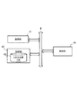
- FIG. 2A is a block diagram showing a functional configuration of the in-vehicle device 1.
- the in-vehicle device 1 mainly includes a communication unit 11, a storage unit 12, a sensor unit 13, an input unit 14, a control unit 15, and an output unit 16. Each of these elements is connected to each other via a bus line.
- the communication unit 11 performs data communication with the server device 4 based on the control of the control unit 15.
- the storage unit 12 stores a program executed by the control unit 15 and information necessary for the control unit 15 to execute a predetermined process.
- the storage unit 12 stores the rider characteristic information IL in advance.
- the lidar characteristic information IL is an example of “characteristic information” in the present invention.
- FIG. 2B is an example of the data structure of the lidar characteristic information IL.
- the lidar characteristic information IL includes installation height information and scan range information.
- the installation height information is information indicating the relative installation height of the rider 2 with respect to the vehicle on which the rider 2 is disposed, and for example, indicates the height with respect to the horizontal plane when the vehicle exists on the horizontal plane.
- the scan range information is information indicating the relative measurable range of the rider 2 with respect to the vehicle. For example, the horizontal angle range and the vertical of the scan by the rider 2 when a predetermined direction (for example, the traveling direction of the vehicle) is used as a reference.
- the angle range the measurable distance of the lidar 2 (that is, the scanning distance), the number of irradiation layers indicating the number of layers of the scan surface irradiated with the laser of the lidar 2 or the number of laser transmission / reception sensors (number of sensors) of the lidar 2; And an interlayer angle indicating an angle between adjacent irradiation surfaces.
- the scan range information is replaced by the number of layers on the scan plane (that is, the number of scan lines) instead of the vertical angle range described above. May also be included.
- the storage unit 12 stores, in advance, the installation height information, the scan range information, and the like that are measured in advance based on, for example, experiments as lidar characteristic information IL.
- the sensor unit 13 is a sensor that detects the state of the vehicle, and includes a GPS receiver 32, an IMU (Internal Measurement Unit) 33, and the like.
- the control unit 15 calculates the predicted host vehicle position Ppr based on the output of the sensor unit 13.
- the sensor unit 13 is an example of the “measurement unit” in the present invention.
- the input unit 14 is a button operated by the user, a touch panel, a remote controller, a voice input device, and the like
- the output unit 16 is, for example, a display or a speaker that performs output based on the control of the control unit 15.
- the control unit 15 includes a CPU that executes a program and controls the entire vehicle-mounted device 1.
- the control unit 15 for example, point group information including the predicted host vehicle position Ppr calculated based on the output of the sensor unit 13 and the lidar characteristic information IL stored in the storage unit 12 at predetermined time intervals.
- the request signal Sr is transmitted to the server device 4 by the communication unit 11.
- the control unit 15 detects the point group indicated by the map point group information Da and the measurement point group output by the lidar 2.
- control unit 15 calculates the predicted own vehicle position Ppr corrected by the error indicated by the error information dP as an estimated value of the own vehicle position.
- the control unit 15 is an example of the “position prediction unit”, “transmission unit”, “reception unit”, and “estimation unit” in the present invention.
- FIG. 3 is a block diagram showing a functional configuration of the server device 4.
- the server device 4 mainly includes a communication unit 41, a storage unit 42, and a control unit 45. Each of these elements is connected to each other via a bus line.
- the communication unit 41 performs data communication with the in-vehicle device 1 based on the control of the control unit 45.
- the storage unit 42 stores a program executed by the control unit 45 and information necessary for the control unit 45 to execute a predetermined process.
- the storage unit 42 stores map data including the three-dimensional point cloud DB 43.
- the three-dimensional point group DB 43 is a database of three-dimensional point group information that forms the surface of a feature existing around each road registered in the map data.
- Each point group registered in the three-dimensional point group DB 43 is represented by, for example, three-dimensional coordinates of latitude / longitude and height (for example, altitude).
- the coordinate system of each point group registered in the three-dimensional point group DB 43 is also referred to as “absolute coordinate system”.
- the point group information registered in the three-dimensional point group DB 43 may be generated from point group information output by a lidar scanned in the horizontal direction and the vertical direction.
- the point cloud information registered in the 3D point cloud DB 43 is a 3D image indicating each feature generated based on the point cloud information output by the lidar, the position information and the shape information of the feature included in the map data, and the like. Point cloud information.
- Each point group information registered in the three-dimensional point group DB 43 is an example of “feature information” in the present invention.
- the control unit 45 includes a CPU that executes a program and the like, and controls the entire server device 4.
- the control unit 45 when the communication unit 41 receives the point group information request signal Sr from the in-vehicle device 1, the control unit 45 includes the predicted host vehicle position Ppr and the rider characteristic information IL included in the point group information request signal Sr. Based on this, the space to be scanned by the lidar 2 is specified. And the control part 45 extracts the map point cloud information Da which shows the point cloud which becomes in the specified scanning object space from 3D point cloud DB43, and the vehicle unit 1 uses the extracted map point cloud information Da by the communication part 41. Send to.
- the control unit 45 is an example of the “acquiring unit”, “output unit” in the present invention, and a computer that executes the program in the present invention.
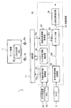
- FIG. 4 is a block diagram showing a functional configuration of the in-vehicle device 1.
- the control unit 15 of the in-vehicle device 1 functionally includes a predicted host vehicle position acquisition unit 51, a lidar characteristic information extraction unit 52, a map point group information acquisition unit 53, and a measurement point group.
- the information acquisition unit 54, the matching unit 55, and the own vehicle position estimation unit 56 are included.
- the predicted vehicle position acquisition unit 51 predicts the two-dimensional or three-dimensional position including the current latitude and longitude and the traveling direction of the vehicle based on the outputs of the GPS receiver 32 and the IMU 33. Then, the predicted host vehicle position acquisition unit 51 includes the predicted position information as the predicted host vehicle position Ppr in the point cloud information request signal Sr, and transmits it to the server device 4 by the communication unit 11.
- the rider characteristic information extraction unit 52 extracts the rider characteristic information IL stored in the storage unit 12, includes the extracted rider characteristic information IL in the point group information request signal Sr, and transmits the point group information request signal Sr to the server device 4.
- the map point cloud information acquisition unit 53 receives the map point cloud information Da transmitted by the server device 4 as a response to the point cloud information request signal Sr by the communication unit 11. Then, the map point group information acquisition unit 53 supplies the received map point group information Da to the matching unit 55.
- the measurement point group information acquisition unit 54 acquires the measurement point group information Db output from the lidar 2 and supplies it to the matching unit 55. In this case, since the map point group information acquisition unit 53 receives only the minimum map point group information Da necessary for matching by the matching unit 55, the communication capacity and the necessary storage capacity can be suitably reduced. The processing load of the matching process with the measurement point group information Db can be suitably reduced.
- the matching unit 55 performs matching (position) between the point cloud indicated by the measurement point cloud information Db acquired from the measurement point cloud information acquisition unit 54 and the point cloud indicated by the map point cloud information Da acquired from the map point cloud information acquisition unit 53. Error information dP is generated.
- the matching unit 55 first acquires the predicted vehicle position Ppr obtained from the predicted vehicle position acquisition unit 51 by using the measurement point cloud information Db represented by the relative coordinate system based on the position and the traveling direction of the vehicle-mounted device 1. Based on, convert to absolute coordinate system.
- the matching unit 55 converts the point cloud indicated by the measurement point cloud information Db converted into the absolute coordinate system and the point cloud indicated by the map point cloud information Da expressed by the absolute coordinate system into an ICP (Iterative Closest Point) or the like.
- the matching is performed using a known matching method.
- the matching unit 55 calculates a vector amount and a rotation angle indicating a displacement necessary for aligning the point group of the measurement point group information Db converted into the absolute coordinate system with the point group of the corresponding map point group information Da.
- the calculated information is supplied to the vehicle position estimation unit 56 as error information dP.
- a specific example of the matching unit 55 will be described with reference to FIGS. 5 and 6.
- the own vehicle position estimation unit 56 acquires the error information dP and the predicted own vehicle position Ppr from the matching unit 55, and estimates the own vehicle position by reflecting the position and orientation deviation indicated by the error information dP in the predicted own vehicle position Ppr. Calculate the value.
- the estimated value of the vehicle position calculated by the vehicle position estimation unit 56 is used for various controls such as automatic driving and route guidance, for example.
- FIG. 5A is a diagram showing a state in which the laser output from the lidar 2 is applied to the features 60 to 62 such as buildings around the vehicle on which the vehicle-mounted device 1 is mounted.
- FIG. 5B is a diagram in which a point group serving as a laser irradiation position in FIG. 5A is extracted.
- a case where the lidar 2 scans only in the horizontal direction is shown.
- the measurement point group information acquisition unit 54 acquires measurement point group information Db corresponding to the point group of the surface positions of the features 60 to 62 existing at the same height as the lidar 2 from the lidar 2, and the matching unit 55 converts the measurement point group information Db acquired by the measurement point group information acquisition unit 54 into three-dimensional coordinates in the absolute coordinate system using the predicted vehicle position Ppr.
- FIG. 6 (A) is a diagram visualizing the point cloud around the vehicle registered in the three-dimensional point cloud DB 43.
- the three-dimensional point cloud DB 43 stores the point cloud information of the three-dimensional surface of the features 60 to 62 and the point cloud information of the edge of the road. Then, when the server device 4 receives the point cloud information request signal Sr, the predicted vehicle position Ppr included in the point cloud information request signal Sr, and the rider characteristic information IL including the installation height information and the scan range information, Based on the above, the scan target space of the lidar 2 is specified, and the map point group information Da indicating the point group in the space is extracted from the three-dimensional point group DB 43.
- FIG. 6B is a diagram in which a point cloud corresponding to the map point cloud information Da transmitted to the vehicle-mounted device 1 is extracted from the point cloud shown in FIG.
- the server device 4 specifies the scan target space by the lidar 2 based on the rider characteristic information IL and the predicted host vehicle position Ppr, and extracts a point group in the specified scan target space.
- the server device 4 recognizes the height of the irradiation surface of the lidar 2 based on the installation height information of the lidar characteristic information IL, and the recognized height and the height within a predetermined distance.
- a point cloud is extracted.
- the server device 4 may determine the height range of the point group extracted from the three-dimensional point group DB 43 according to the range. In this case, the server device 4 may make the vertical scan range included in the scan range information the same as the height range of the point group extracted from the three-dimensional point group DB 43, and the rider 2 due to the posture change of the traveling vehicle.
- the height range of the point group extracted from the three-dimensional point group DB 43 may be made somewhat larger than the vertical scan range included in the scan range information.
- the server device 4 recognizes the scan range on the horizontal plane of the rider 2 on the horizontal plane based on the scan range information of the rider characteristic information IL and the predicted vehicle position Ppr. A point cloud of the features 60 to 62 existing in the scan range is extracted.
- the server device 4 extracts a point group corresponding to the number of irradiation layers based on information indicating the number of irradiation layers (or the number of laser transmission / reception sensors of the lidar 2) included in the scan range information of the lidar characteristic information IL. May be.
- the server device 4 determines the height range of the point group extracted from the three-dimensional point cloud DB 43 based on the information indicating the angle between the irradiation layers included in the scan range information. May be.
- the server device 4 adds the altitude of the road surface on which the vehicle exists to the installation height information to irradiate the lidar 2. Calculate the elevation of the surface.
- the predicted host vehicle position Ppr included in the point cloud information request signal Sr includes information on the altitude of the vehicle based on the output of the GPS receiver 32 or the like. Based on the information, the altitude of the road surface on which the vehicle is present is recognized.
- the server device 4 recognizes the altitude of the road surface on which the vehicle is present based on the altitude information when the road data corresponding to the road on which the vehicle is present includes the altitude information.
- the matching unit 55 converts the point group shown in FIG. 5B (that is, the point group indicated by the measurement point group information Db) converted into the absolute coordinate system and the point group shown in FIG. 6B (that is, map points). Alignment with the point group indicated by the group information Da) is performed. Then, the matching unit 55 generates error information dP corresponding to the vector amount and the rotation angle indicating the deviation of the point group shown in FIG. 5B converted from the point group shown in FIG. 5B with respect to the point group shown in FIG. 6B. To do.
- the in-vehicle device 1 receives only the minimum map point group information Da necessary for matching by the matching unit 55 from the server device 4, so that the communication capacity and the necessary storage capacity are reduced.
- the processing load of the matching process can be suitably reduced.
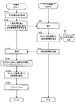
- FIG. 7 is a flowchart showing the procedure of the vehicle position estimation process in the present embodiment.
- the in-vehicle device 1 repeatedly executes the flowchart shown in FIG.
- the in-vehicle device 1 acquires the predicted own vehicle position Ppr indicating the current latitude, longitude, traveling direction of the vehicle, and the like based on the outputs of the GPS receiver 32 and the IMU 33 (step S101).
- the predicted vehicle position Ppr may be information including the current altitude measured by the GPS receiver 32 or the like.
- the vehicle equipment 1 transmits the point cloud information request
- the server device 4 receives the point cloud information request signal Sr transmitted from the vehicle-mounted device 1 (step S201). Then, the server device 4 recognizes the scan target space to be scanned by the lidar 2 in the absolute coordinate system based on the predicted host vehicle position Ppr and the lidar characteristic information IL included in the point cloud information request signal Sr, and Map point group information Da indicating the point group in the scan target space is extracted from the three-dimensional point group DB 43 (step S202). And the server apparatus 4 transmits the map point cloud information Da extracted from 3D point cloud DB43 to the vehicle equipment 1 (step S203).
- the in-vehicle device 1 receives the map point cloud information Da from the server device 4 (step S103).
- the in-vehicle device 1 performs matching using the measurement point group information Db acquired from the lidar 2 and the received map point group information Da (step S104).
- the vehicle equipment 1 calculates error information dP based on a matching result (step S105).
- the vehicle equipment 1 calculates the estimated value of the own vehicle position by correcting the predicted own vehicle position Ppr calculated in step S101 based on the calculated error information dP (step S106).
- the server apparatus 4 stores the three-dimensional point cloud DB 43 and receives the point cloud information request signal Sr including the rider characteristic information IL regarding the characteristics of the rider 2 and the predicted own vehicle position Ppr.
- the server device 4 extracts map point group information Da corresponding to the point group in the specified scan target space from the three-dimensional point group DB 43 and transmits it to the in-vehicle device 1.
- the in-vehicle device 1 since the in-vehicle device 1 receives only the minimum map point group information Da necessary for matching, the communication capacity and the necessary storage capacity can be suitably reduced, and the measurement point group information Db can be reduced.
- the processing load of the matching process can be suitably reduced.
- the server device 4 may be composed of a plurality of servers.
- a server that stores the three-dimensional point cloud DB 43 and a server that executes the processes of steps S201 to S203 in FIG. 7 may be configured separately.
- each server receives the information required in order to perform the process allocated previously from another server, and performs a required process.
Landscapes
- Engineering & Computer Science (AREA)
- Radar, Positioning & Navigation (AREA)
- Remote Sensing (AREA)
- Physics & Mathematics (AREA)
- General Physics & Mathematics (AREA)
- Computer Networks & Wireless Communication (AREA)
- Electromagnetism (AREA)
- Automation & Control Theory (AREA)
- Multimedia (AREA)
- Theoretical Computer Science (AREA)
- Traffic Control Systems (AREA)
- Navigation (AREA)
Priority Applications (4)
| Application Number | Priority Date | Filing Date | Title |
|---|---|---|---|
| US16/302,078 US20200183009A1 (en) | 2016-05-17 | 2016-05-17 | Information output device, terminal device, control method, program and storage medium |
| JP2018517966A JPWO2017199333A1 (ja) | 2016-05-17 | 2016-05-17 | 情報出力装置、端末装置、制御方法、プログラム及び記憶媒体 |
| EP16902353.8A EP3460779A4 (de) | 2016-05-17 | 2016-05-17 | Informationsausgabevorrichtung, endgerätevorrichtung, steuerungsverfahren, programm und speichermedium |
| PCT/JP2016/064598 WO2017199333A1 (ja) | 2016-05-17 | 2016-05-17 | 情報出力装置、端末装置、制御方法、プログラム及び記憶媒体 |
Applications Claiming Priority (1)
| Application Number | Priority Date | Filing Date | Title |
|---|---|---|---|
| PCT/JP2016/064598 WO2017199333A1 (ja) | 2016-05-17 | 2016-05-17 | 情報出力装置、端末装置、制御方法、プログラム及び記憶媒体 |
Publications (1)
| Publication Number | Publication Date |
|---|---|
| WO2017199333A1 true WO2017199333A1 (ja) | 2017-11-23 |
Family
ID=60324993
Family Applications (1)
| Application Number | Title | Priority Date | Filing Date |
|---|---|---|---|
| PCT/JP2016/064598 Ceased WO2017199333A1 (ja) | 2016-05-17 | 2016-05-17 | 情報出力装置、端末装置、制御方法、プログラム及び記憶媒体 |
Country Status (4)
| Country | Link |
|---|---|
| US (1) | US20200183009A1 (de) |
| EP (1) | EP3460779A4 (de) |
| JP (1) | JPWO2017199333A1 (de) |
| WO (1) | WO2017199333A1 (de) |
Cited By (9)
| Publication number | Priority date | Publication date | Assignee | Title |
|---|---|---|---|---|
| JP2019109332A (ja) * | 2017-12-18 | 2019-07-04 | パイオニア株式会社 | 地図データ構造 |
| JP2019117434A (ja) * | 2017-12-26 | 2019-07-18 | パイオニア株式会社 | 画像生成装置 |
| CN111242799A (zh) * | 2019-12-10 | 2020-06-05 | 国网通用航空有限公司 | 基于机载LiDAR点云的高压线塔中心坐标提取编号方法及介质 |
| JP2021514886A (ja) * | 2019-01-30 | 2021-06-17 | バイドゥドットコム タイムズ テクロノジー (ベイジン) カンパニー リミテッドBaidu.com Times Technology (Beijing) Co., Ltd. | 自動運転車のためのポイントクラウド登録システム |
| JP2021105584A (ja) * | 2019-12-27 | 2021-07-26 | 日産自動車株式会社 | 位置推定方法及び位置推定装置 |
| EP3882869A4 (de) * | 2018-11-16 | 2021-12-15 | Korea Advanced Institute of Science and Technology | Verfahren und vorrichtung zur anpassung eines starklaserscanners unter berücksichtigung der bewegung eines bodenroboters |
| JP2022106885A (ja) * | 2017-12-26 | 2022-07-20 | パイオニア株式会社 | 画像生成装置 |
| JP2022109525A (ja) * | 2021-01-15 | 2022-07-28 | Cellid株式会社 | 情報処理システム及び情報処理方法 |
| WO2023105595A1 (ja) * | 2021-12-06 | 2023-06-15 | 日本電信電話株式会社 | 位置姿勢推定方法、位置姿勢推定装置、及びプログラム |
Families Citing this family (2)
| Publication number | Priority date | Publication date | Assignee | Title |
|---|---|---|---|---|
| GB2559157A (en) * | 2017-01-27 | 2018-08-01 | Ucl Business Plc | Apparatus, method and system for alignment of 3D datasets |
| DE102022203267A1 (de) | 2022-04-01 | 2023-10-05 | Robert Bosch Gesellschaft mit beschränkter Haftung | Verfahren zur Lokalisierung eines Fahrzeugs mittels entfernungsbasierter Sensordaten des Fahrzeugs |
Citations (4)
| Publication number | Priority date | Publication date | Assignee | Title |
|---|---|---|---|---|
| JP2008165275A (ja) | 2006-12-27 | 2008-07-17 | Yaskawa Electric Corp | 自己位置同定装置を備えた移動体 |
| JP2009264983A (ja) * | 2008-04-25 | 2009-11-12 | Mitsubishi Electric Corp | 位置標定装置、位置標定システム、位置標定システムのユーザインタフェース装置、位置標定システムの標定サーバ装置および位置標定方法 |
| JP2011027594A (ja) * | 2009-07-27 | 2011-02-10 | Toyota Infotechnology Center Co Ltd | 地図データ検証システム |
| WO2012086029A1 (ja) * | 2010-12-22 | 2012-06-28 | 株式会社日立製作所 | 自律移動システム |
Family Cites Families (7)
| Publication number | Priority date | Publication date | Assignee | Title |
|---|---|---|---|---|
| AU2009211435A1 (en) * | 2008-02-04 | 2009-08-13 | Tele Atlas B.V. | Method for map matching with sensor detected objects |
| KR101269981B1 (ko) * | 2008-08-29 | 2013-05-31 | 미쓰비시덴키 가부시키가이샤 | 부감 화상 생성장치, 부감 화상 생성방법 및 기록매체 |
| US20140379254A1 (en) * | 2009-08-25 | 2014-12-25 | Tomtom Global Content B.V. | Positioning system and method for use in a vehicle navigation system |
| US8825371B2 (en) * | 2012-12-19 | 2014-09-02 | Toyota Motor Engineering & Manufacturing North America, Inc. | Navigation of on-road vehicle based on vertical elements |
| US9043072B1 (en) * | 2013-04-04 | 2015-05-26 | Google Inc. | Methods and systems for correcting an estimated heading using a map |
| JP6325806B2 (ja) * | 2013-12-06 | 2018-05-16 | 日立オートモティブシステムズ株式会社 | 車両位置推定システム |
| JPWO2017208396A1 (ja) * | 2016-06-01 | 2019-03-14 | パイオニア株式会社 | 地物データ構造、記憶媒体、情報処理装置及び検出装置 |
-
2016
- 2016-05-17 WO PCT/JP2016/064598 patent/WO2017199333A1/ja not_active Ceased
- 2016-05-17 EP EP16902353.8A patent/EP3460779A4/de not_active Withdrawn
- 2016-05-17 JP JP2018517966A patent/JPWO2017199333A1/ja not_active Withdrawn
- 2016-05-17 US US16/302,078 patent/US20200183009A1/en not_active Abandoned
Patent Citations (4)
| Publication number | Priority date | Publication date | Assignee | Title |
|---|---|---|---|---|
| JP2008165275A (ja) | 2006-12-27 | 2008-07-17 | Yaskawa Electric Corp | 自己位置同定装置を備えた移動体 |
| JP2009264983A (ja) * | 2008-04-25 | 2009-11-12 | Mitsubishi Electric Corp | 位置標定装置、位置標定システム、位置標定システムのユーザインタフェース装置、位置標定システムの標定サーバ装置および位置標定方法 |
| JP2011027594A (ja) * | 2009-07-27 | 2011-02-10 | Toyota Infotechnology Center Co Ltd | 地図データ検証システム |
| WO2012086029A1 (ja) * | 2010-12-22 | 2012-06-28 | 株式会社日立製作所 | 自律移動システム |
Non-Patent Citations (1)
| Title |
|---|
| See also references of EP3460779A4 |
Cited By (17)
| Publication number | Priority date | Publication date | Assignee | Title |
|---|---|---|---|---|
| JP2019109332A (ja) * | 2017-12-18 | 2019-07-04 | パイオニア株式会社 | 地図データ構造 |
| JP7333445B2 (ja) | 2017-12-26 | 2023-08-24 | パイオニア株式会社 | 画像生成装置 |
| JP2019117434A (ja) * | 2017-12-26 | 2019-07-18 | パイオニア株式会社 | 画像生成装置 |
| JP2022106885A (ja) * | 2017-12-26 | 2022-07-20 | パイオニア株式会社 | 画像生成装置 |
| EP3882869A4 (de) * | 2018-11-16 | 2021-12-15 | Korea Advanced Institute of Science and Technology | Verfahren und vorrichtung zur anpassung eines starklaserscanners unter berücksichtigung der bewegung eines bodenroboters |
| US12080071B2 (en) | 2018-11-16 | 2024-09-03 | Korea Advanced Institute Of Science And Technology | Strong laser scanner matching method and apparatus considering movement of ground robot |
| JP2021514886A (ja) * | 2019-01-30 | 2021-06-17 | バイドゥドットコム タイムズ テクロノジー (ベイジン) カンパニー リミテッドBaidu.com Times Technology (Beijing) Co., Ltd. | 自動運転車のためのポイントクラウド登録システム |
| JP7248208B2 (ja) | 2019-01-30 | 2023-03-29 | バイドゥドットコム タイムズ テクノロジー (ベイジン) カンパニー リミテッド | 自動運転車のためのポイントクラウド登録システム |
| CN111242799A (zh) * | 2019-12-10 | 2020-06-05 | 国网通用航空有限公司 | 基于机载LiDAR点云的高压线塔中心坐标提取编号方法及介质 |
| CN111242799B (zh) * | 2019-12-10 | 2024-01-16 | 国网电力空间技术有限公司 | 基于机载LiDAR点云的高压线塔中心坐标提取编号方法及介质 |
| JP2021105584A (ja) * | 2019-12-27 | 2021-07-26 | 日産自動車株式会社 | 位置推定方法及び位置推定装置 |
| JP7408236B2 (ja) | 2019-12-27 | 2024-01-05 | 日産自動車株式会社 | 位置推定方法及び位置推定装置 |
| JP2022109525A (ja) * | 2021-01-15 | 2022-07-28 | Cellid株式会社 | 情報処理システム及び情報処理方法 |
| JP7641533B2 (ja) | 2021-01-15 | 2025-03-07 | Cellid株式会社 | 情報処理システム及び情報処理方法 |
| JPWO2023105595A1 (de) * | 2021-12-06 | 2023-06-15 | ||
| WO2023105595A1 (ja) * | 2021-12-06 | 2023-06-15 | 日本電信電話株式会社 | 位置姿勢推定方法、位置姿勢推定装置、及びプログラム |
| JP7694704B2 (ja) | 2021-12-06 | 2025-06-18 | 日本電信電話株式会社 | 位置姿勢推定方法、位置姿勢推定装置、及びプログラム |
Also Published As
| Publication number | Publication date |
|---|---|
| EP3460779A1 (de) | 2019-03-27 |
| EP3460779A4 (de) | 2020-01-01 |
| US20200183009A1 (en) | 2020-06-11 |
| JPWO2017199333A1 (ja) | 2019-03-14 |
Similar Documents
| Publication | Publication Date | Title |
|---|---|---|
| WO2017199333A1 (ja) | 情報出力装置、端末装置、制御方法、プログラム及び記憶媒体 | |
| JP7843399B2 (ja) | 判定装置 | |
| JP6721784B2 (ja) | 情報処理装置、サーバ装置、制御方法、プログラム及び記憶媒体 | |
| CN109425346B (zh) | 用于自动化车辆的导航系统 | |
| KR101625486B1 (ko) | 지도 기반 측위 시스템 및 그 방법 | |
| JP6442193B2 (ja) | 点群位置データ処理装置、点群位置データ処理システム、点群位置データ処理方法およびプログラム | |
| US9767372B2 (en) | Target detection apparatus and target detection method | |
| US20180154901A1 (en) | Method and system for localizing a vehicle | |
| CN106575475B (zh) | 信息管理装置、车辆及信息管理方法 | |
| JP7155284B2 (ja) | 計測精度算出装置、自己位置推定装置、制御方法、プログラム及び記憶媒体 | |
| JP7032062B2 (ja) | 点群データ処理装置、移動ロボット、移動ロボットシステム、および点群データ処理方法 | |
| JP6330471B2 (ja) | 無線測位装置 | |
| WO2021112074A1 (ja) | 情報処理装置、制御方法、プログラム及び記憶媒体 | |
| JP2025123341A (ja) | 位置推定装置、推定装置、制御方法、プログラム及び記憶媒体 | |
| US20220113139A1 (en) | Object recognition device, object recognition method and program | |
| KR20180066618A (ko) | 자율주행차량을 위한 거리 데이터와 3차원 스캔 데이터의 정합 방법 및 그 장치 | |
| JPWO2018212294A1 (ja) | 自己位置推定装置、制御方法、プログラム及び記憶媒体 | |
| JPWO2018212292A1 (ja) | 情報処理装置、制御方法、プログラム及び記憶媒体 | |
| WO2018221455A1 (ja) | 更新装置、制御方法、プログラム及び記憶媒体 | |
| JP2018116014A (ja) | 自車位置推定装置、制御方法、プログラム及び記憶媒体 | |
| JP2022176322A (ja) | 自己位置推定装置、制御方法、プログラム及び記憶媒体 | |
| JP2023076673A (ja) | 情報処理装置、制御方法、プログラム及び記憶媒体 | |
| JP2019148456A (ja) | 算出装置、自己位置算出方法、およびプログラム | |
| WO2019188886A1 (ja) | 端末装置、情報処理方法、プログラム、及び、記憶媒体 | |
| JP2022093703A (ja) | 情報出力装置、端末装置、制御方法、プログラム及び記憶媒体 |
Legal Events
| Date | Code | Title | Description |
|---|---|---|---|
| ENP | Entry into the national phase |
Ref document number: 2018517966 Country of ref document: JP Kind code of ref document: A |
|
| NENP | Non-entry into the national phase |
Ref country code: DE |
|
| 121 | Ep: the epo has been informed by wipo that ep was designated in this application |
Ref document number: 16902353 Country of ref document: EP Kind code of ref document: A1 |
|
| ENP | Entry into the national phase |
Ref document number: 2016902353 Country of ref document: EP Effective date: 20181217 |