WO2017199375A1 - Dispositif de transmission d'énergie sans contact - Google Patents
Dispositif de transmission d'énergie sans contact Download PDFInfo
- Publication number
- WO2017199375A1 WO2017199375A1 PCT/JP2016/064751 JP2016064751W WO2017199375A1 WO 2017199375 A1 WO2017199375 A1 WO 2017199375A1 JP 2016064751 W JP2016064751 W JP 2016064751W WO 2017199375 A1 WO2017199375 A1 WO 2017199375A1
- Authority
- WO
- WIPO (PCT)
- Prior art keywords
- power transmission
- power supply
- unit
- air
- power
- Prior art date
- Legal status (The legal status is an assumption and is not a legal conclusion. Google has not performed a legal analysis and makes no representation as to the accuracy of the status listed.)
- Ceased
Links
Images



Classifications
-
- H—ELECTRICITY
- H02—GENERATION; CONVERSION OR DISTRIBUTION OF ELECTRIC POWER
- H02J—ELECTRIC POWER NETWORKS; CIRCUIT ARRANGEMENTS OR SYSTEMS FOR SUPPLYING OR DISTRIBUTING ELECTRIC POWER; SYSTEMS FOR STORING ELECTRIC ENERGY
- H02J50/00—Circuit arrangements or systems for wireless supply or distribution of electric power
- H02J50/10—Circuit arrangements or systems for wireless supply or distribution of electric power using inductive coupling
-
- B—PERFORMING OPERATIONS; TRANSPORTING
- B60—VEHICLES IN GENERAL
- B60M—POWER SUPPLY LINES, AND DEVICES ALONG RAILS, FOR ELECTRICALLY- PROPELLED VEHICLES
- B60M7/00—Power lines or rails specially adapted for electrically-propelled vehicles of special types, e.g. suspension tramway, ropeway, underground railway
Definitions
- the present invention relates to a contactless power transmission device that transmits power in a contactless manner.
- a non-contact power transmission device that transmits electric power to an electric vehicle in a non-contact manner includes a power transmission unit that includes a power transmission coil, and the power transmission unit is installed at a suitable location in a parking space. Since such a power transmission unit is a closed space, if the power transmission coil is excited during power transmission, the temperature in the power transmission unit may increase due to heat generation. Therefore, Patent Document 1 discloses that an intake port is provided in the power transmission unit to ventilate the inside of the power transmission unit to suppress a temperature rise.
- Patent Document 1 since the conventional example disclosed in Patent Document 1 is provided with an intake port in the power transmission unit, there is a possibility that foreign matters such as muddy water and dust may enter from the intake port. As a result, foreign matter is clogged inside the power transmission unit, and it has been difficult to efficiently cool the power transmission unit.
- the present invention has been made to solve such a conventional problem, and an object of the present invention is to provide a non-contact power transmission device capable of preventing foreign matter from entering the power transmission unit. is there.
- a contactless power transmission device includes a power transmission unit in which a power transmission coil is housed, a power source unit in which a power supply device is housed, and a power source unit that communicates with the power transmission unit.
- a ventilation duct is provided to send air to the power transmission unit.
- FIG. 1 is an explanatory diagram illustrating a configuration of the contactless power transmission device according to the first embodiment.
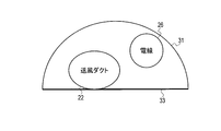
- FIG. 2 is a cross-sectional view illustrating the internal configuration of the connection portion of the non-contact power transmission apparatus according to the first embodiment.
- FIG. 3 is an explanatory diagram illustrating a configuration of the contactless power transmission device according to the second embodiment.
- FIG. 4 is a cross-sectional view illustrating the internal configuration of the connection portion of the non-contact power transmission apparatus according to the second embodiment.
- FIG. 5 is a cross-sectional view illustrating another example of the internal configuration of the connection portion of the contactless power transmission device according to the second embodiment.
- FIG. 6 is an explanatory diagram illustrating a configuration of the contactless power transmission device according to the third embodiment.
- FIG. 1 is an explanatory diagram showing the configuration of the non-contact power transmission apparatus according to the first embodiment of the present invention.
- the non-contact power transmission apparatus 101 according to the first embodiment supplies power to the power transmission unit 11 that is installed in the vicinity of the parking space and the power transmission unit 11 provided on the ground of the parking space on the ground.
- the power transmission unit 11 has a structure in which the upper surface is closed in order to prevent foreign matters such as muddy water and dust from entering the inside.
- a power transmission coil 21 is housed inside the power transmission unit 11, and power can be transmitted using the power transmission coil 21. That is, when an electric vehicle (not shown) stops at an appropriate position in the parking space and the power receiving coil of the electric vehicle is disposed at a position facing the power transmitting coil 21, the power transmitting coil 21 is excited to contact the electric vehicle. The power can be transmitted to the power receiving coil side. Further, the power transmission unit 11 is provided with an exhaust hole 25 for exhausting air staying inside.
- the power supply unit 12 has a closed casing shape, and a power supply device 23 for supplying power to the power transmission coil 21 is provided inside.
- An air inlet 24 for introducing outside air into the power supply unit 12 is provided.
- the power supply device 23 includes a rectifier circuit that converts AC power supplied from an external commercial power supply (not shown) into DC, an inverter circuit that converts the rectified power into AC having a desired frequency, and the like.
- the power supply device 23 is disposed at a position higher than the intake port 24.
- connection part 13 the electric wire 26 for connecting the power supply device 23 and the power transmission coil 21 is installed. Therefore, the alternating current output from the power supply device 23 is supplied to the power transmission coil 21 via the electric wire 26. Further, a blower duct 22 that communicates between the power supply unit 12 and the power transmission unit 11 is provided in the connection unit 13. One end of the air duct 22 is connected to the suction unit 27 of the power supply unit 12, and the other end is connected to the power transmission unit 11. The suction unit 27 is disposed at a position lower than the intake port 24. Further, as described above, since the power supply device 23 is disposed at a position higher than the intake port 24, the power supply device 23 is located at a position higher than the suction portion 27. For this reason, it can suppress as much as possible that the air heated with the power supply device 23 introduce
- FIG. 2 is a cross-sectional view of the connecting portion 13, and as shown in FIG. 2, a wiring cover 31 having a semicircular cross section that covers the ground 33 is provided.
- the air duct 22 and the electric wires 26 are arranged.
- the air duct 22 is in contact with the ground 33.
- the connection part 13 can also be set as the structure which forms a groove
- the operation of the non-contact power transmission apparatus 101 When performing non-contact power transmission, the output power of the power supply device 23 is supplied to the power transmission coil 21 via the electric wire 26. Then, the power transmission coil 21 is excited. At this time, since the power transmission coil 21 generates heat, the internal air of the power transmission unit 11 is heated and the temperature rises.
- external air air having a low temperature
- this air is introduced from the air inlet 24 provided in the power supply unit 12, and this air is introduced from the suction unit 27 to the air duct 22, and further, via the air duct 22, It is supplied into the power transmission unit 11. That is, since the low-temperature air flows downward, an airflow from the suction unit 27 toward the power transmission unit 11 is naturally generated. Therefore, external air is introduced into the power transmission unit 11, and the inside of the power transmission unit 11 can be cooled. And the air in the power transmission part 11 is discharged
- the air inlet 24 is provided in the power supply unit 12, and further, air is blown into the connection unit 13 between the power supply unit 12 and the power transmission unit 11.
- a duct 22 is provided. Therefore, external air introduced into the power supply unit 12 from the air inlet 24 can be supplied into the power transmission unit 11, and the power transmission unit 11 can be cooled.
- the power transmission part 11 since the power transmission part 11 is not provided with an inlet port, it can avoid that foreign materials, such as muddy water and garbage, penetrate
- the suction part 27 of the air duct 22 is provided at a position lower than the intake port 24 in the power supply unit 12, the low-temperature air introduced from the intake port 24 in the power supply unit 12 is sucked in the suction unit 27. More introduced. That is, since air having a relatively low temperature can be supplied into the power transmission unit 11, the cooling efficiency in the power transmission unit 11 can be increased.
- the power supply device 23 is disposed at a position higher than the intake port 24, so that it is possible to avoid introducing air heated by the power supply device 23 into the air duct 22. it can.
- the air duct 22 disposed in the connection portion 13 is disposed so as to contact the ground 33 having a relatively low temperature, the air flowing through the air duct 22 can be cooled. Therefore, the cooling efficiency in the power transmission unit 11 can be further improved.
- a cooling device (not shown) for cooling the air supplied to the blower duct 22 is provided in the vicinity of the suction part 27 of the blower duct 22 of the power supply unit 12. Is also possible. With such a configuration, the cooling efficiency of the power transmission unit 11 can be further improved.
- an exhaust port (not shown) for discharging the air of the power supply unit 12 to the outside can be provided at an appropriate position above the power supply unit 12.
- the air heated by the power supply device 23 can be efficiently discharged to the outside, the temperature rise of the air in the power supply unit 12 can be suppressed, and as a result, the cooling efficiency in the power transmission unit 11 can be suppressed. Can be improved.
- the wiring cover 31 may be divided into a plurality of parts along the longitudinal direction. With such a configuration, it is possible to easily remove the wiring cover 31 and perform maintenance or the like.
- FIG. 3 is an explanatory diagram showing the configuration of the non-contact power transmission apparatus according to the second embodiment of the present invention.
- the non-contact power transmission apparatus 102 according to the second embodiment is installed in the vicinity of the power transmission unit 11 a provided on the ground of the parking space and the parking space, as in the first embodiment described above.
- a power supply unit 12a that supplies power to the power transmission unit 11a
- a connection unit 13a that connects the power transmission unit 11a and the power supply unit 12a.
- the power transmission unit 11a is different from the power transmission unit 11 shown in FIG. 1 of the first embodiment in that the exhaust hole 25 is not provided. Since other configurations are the same as those in FIG. 1, detailed description thereof is omitted.
- connection part 13a is provided with an electric wire 26 for connecting the power supply device 23 and the power transmission coil 21 as in the first embodiment.
- a blower duct 32 that communicates between the power supply unit 12a and the power transmission unit 11a is provided in the connection unit 13a, and an exhaust duct 42 that communicates between the power transmission unit 11a and the power supply unit 12a.
- the ventilation duct 32 and the exhaust duct 42 are comprised by one duct is shown. That is, the air sent from the suction part 27 to the power transmission part 11a via the air duct 32 is returned to the power supply part 12a via the exhaust duct 42 and introduced into the power supply part 12a from the exhaust part 29.
- the air duct 32 is in contact with the ground 33, and the exhaust duct 42 is disposed so as not to contact the ground 33. For this reason, the air flowing through the air duct 32 can be cooled, and heat generated from the exhaust duct 42 can be prevented from being transmitted to the air duct 32 through the ground 33.
- the power supply unit 12a includes the exhaust unit 29 of the exhaust duct 42 and the exhaust port 30 at an appropriate upper position. Is different. Since other configurations are the same as those in FIG. 1, the same reference numerals are given and detailed description thereof is omitted.
- the exhaust port 30 is an opening for discharging the air in the power supply unit 12 a to the outside, and is disposed at a position higher than the intake port 24.
- the operation of the non-contact power transmission apparatus 101 according to the second embodiment will be described.
- the voltage output from the power supply device 23 is supplied to the power transmission coil 21 via the electric wire 26. Then, the power transmission coil 21 is excited. At this time, since the power transmission coil 21 generates heat, the air inside the power transmission unit 11a is heated and the temperature rises.
- the exhaust part 29 is provided at a position higher than the suction part 27, the high-temperature air introduced into the power supply part 12a from the exhaust part 29 rises in the power supply part 12a, and the exhaust port 30 is discharged to the outside.
- the air inlet 24 is provided in the power supply unit 12a, and the air duct 32 and the power transmission unit 11a are further provided between the power supply unit 12a and the power transmission unit 11a.
- An exhaust duct 42 is provided. Therefore, it is possible to cool the inside of the power transmission unit 11a using external air introduced into the inside through the air inlet 24.
- the power transmission part 11a since the power transmission part 11a is not provided with an inlet port, it can avoid that foreign materials, such as rainwater and mud, penetrate
- the suction portion 27 of the air duct 32 is provided at a position lower than the intake port 24 in the power supply unit 12a, the low-temperature air introduced from the intake port 24 in the power supply unit 12a is the suction unit 27. As a result, the cooling efficiency in the power transmission unit 11a can be increased.
- the power supply device 23 is disposed at a position higher than the intake port 24 in the power supply unit 12a, contact between the air heated by the power supply device 23 and the air introduced from the intake port 24 is minimized. Can be suppressed. Therefore, it is possible to avoid introduction of air heated by the power supply device 23 into the air duct 22.
- the exhaust part 29 is arranged at a position higher than the intake port 24, the high-temperature air in the power supply part 12a can be efficiently exhausted to the outside.
- the air duct 32 is in contact with the ground 33, and the air flowing through the air duct 32 is cooled. Therefore, the cooling efficiency in the power transmission unit 11a can be further improved. Further, since the exhaust duct 42 is not in contact with the ground 33, heat generated from the exhaust duct 42 can be prevented from being transmitted to the blower duct 32 through the ground 33, and cooling efficiency can be further increased. It becomes possible. Furthermore, the cooling efficiency can be improved by disposing the exhaust duct 42 at a position as far away as possible from the blower duct 22.
- the second embodiment may have a configuration in which a cooling device (not shown) is provided in the vicinity of the suction unit 27 in the power supply unit 12a, as in the first embodiment described above. Furthermore, it is good also as a structure which can divide
- FIG. 5 is a cross-sectional view of a connecting portion 13a according to a modification.
- the heat insulating material 61 is filled in the connection portion 13a. Therefore, even when the temperature of the wiring cover 31 rises due to sunlight shining on the wiring cover 31 or the like, it is possible to prevent heat from being transmitted to the air duct 32, and to further improve the cooling efficiency of the power transmission unit 11a. It becomes possible to improve.
- FIG. 6 is an explanatory diagram showing the configuration of the non-contact power transmission apparatus according to the third embodiment of the present invention.
- the non-contact power transmission apparatus 103 according to the third embodiment includes a power transmission unit 11b, a power supply unit 12b, and a connection unit 13b.
- the ventilation duct 32 and the exhaust duct 42 are isolate
- the end of the exhaust duct 42 on the power transmission unit 11b side is connected to an exhaust hole 40 provided in the power transmission unit 11b.
- the air introduced into the power transmission unit 11b from the blower duct 32 passes through the power transmission unit 11b. Thereafter, the air is returned to the power supply unit 12b via the exhaust hole 40 and the exhaust duct 42.
- the contactless power transmission device of the present invention has been described based on the illustrated embodiment.
- the present invention is not limited to this, and the configuration of each part is replaced with an arbitrary configuration having the same function. be able to.
Landscapes
- Engineering & Computer Science (AREA)
- Computer Networks & Wireless Communication (AREA)
- Power Engineering (AREA)
- Mechanical Engineering (AREA)
- General Details Of Gearings (AREA)
Abstract
La présente invention comporte : une unité d'émission d'énergie (11), qui est disposée sur le sol, et qui renferme en son sein une bobine d'émission d'énergie (21) qui émet de l'énergie de transmission sans contact; une unité d'alimentation électrique (12) qui renferme en son sein un dispositif d'alimentation électrique (23) qui fournit de l'électricité à l'unité d'émission d'énergie (11); et une conduite d'air (22), qui est en communication avec l'unité d'alimentation électrique (12) jusqu'à l'unité d'émission d'énergie (11), et qui envoie de l'air présent dans l'unité d'alimentation électrique (12) à l'unité d'émission d'énergie (11). L'unité d'alimentation électrique (12) comporte un orifice d'admission (24) permettant d'introduire de l'air extérieur, et l'orifice d'admission (24) est disposé à une position plus haute que celle d'une section d'aspiration (27) de la conduite d'air (22).
Priority Applications (1)
| Application Number | Priority Date | Filing Date | Title |
|---|---|---|---|
| PCT/JP2016/064751 WO2017199375A1 (fr) | 2016-05-18 | 2016-05-18 | Dispositif de transmission d'énergie sans contact |
Applications Claiming Priority (1)
| Application Number | Priority Date | Filing Date | Title |
|---|---|---|---|
| PCT/JP2016/064751 WO2017199375A1 (fr) | 2016-05-18 | 2016-05-18 | Dispositif de transmission d'énergie sans contact |
Publications (1)
| Publication Number | Publication Date |
|---|---|
| WO2017199375A1 true WO2017199375A1 (fr) | 2017-11-23 |
Family
ID=60325083
Family Applications (1)
| Application Number | Title | Priority Date | Filing Date |
|---|---|---|---|
| PCT/JP2016/064751 Ceased WO2017199375A1 (fr) | 2016-05-18 | 2016-05-18 | Dispositif de transmission d'énergie sans contact |
Country Status (1)
| Country | Link |
|---|---|
| WO (1) | WO2017199375A1 (fr) |
Cited By (2)
| Publication number | Priority date | Publication date | Assignee | Title |
|---|---|---|---|---|
| CN109969022A (zh) * | 2019-03-27 | 2019-07-05 | 成都宇坤健元新能源科技有限公司 | 一种节能环保大功率充电桩及其冷却方法 |
| WO2022213157A1 (fr) * | 2021-04-08 | 2022-10-13 | Lumen Intellectual Property Pty Ltd | Ensemble de charge sans fil pour véhicule électrique |
Citations (4)
| Publication number | Priority date | Publication date | Assignee | Title |
|---|---|---|---|---|
| JPH07169628A (ja) * | 1993-08-09 | 1995-07-04 | Hughes Aircraft Co | 冷却された1次部分を有する自動車バッテリ充電変圧器 |
| JP2012216569A (ja) * | 2011-03-31 | 2012-11-08 | Equos Research Co Ltd | 電力伝送システム |
| JP2013147142A (ja) * | 2012-01-19 | 2013-08-01 | Yazaki Corp | コイルユニットの設置構造 |
| WO2014200024A1 (fr) * | 2013-06-13 | 2014-12-18 | 矢崎総業株式会社 | Dispositif d'alimentation en puissance et système d'alimentation en puissance |
-
2016
- 2016-05-18 WO PCT/JP2016/064751 patent/WO2017199375A1/fr not_active Ceased
Patent Citations (4)
| Publication number | Priority date | Publication date | Assignee | Title |
|---|---|---|---|---|
| JPH07169628A (ja) * | 1993-08-09 | 1995-07-04 | Hughes Aircraft Co | 冷却された1次部分を有する自動車バッテリ充電変圧器 |
| JP2012216569A (ja) * | 2011-03-31 | 2012-11-08 | Equos Research Co Ltd | 電力伝送システム |
| JP2013147142A (ja) * | 2012-01-19 | 2013-08-01 | Yazaki Corp | コイルユニットの設置構造 |
| WO2014200024A1 (fr) * | 2013-06-13 | 2014-12-18 | 矢崎総業株式会社 | Dispositif d'alimentation en puissance et système d'alimentation en puissance |
Cited By (2)
| Publication number | Priority date | Publication date | Assignee | Title |
|---|---|---|---|---|
| CN109969022A (zh) * | 2019-03-27 | 2019-07-05 | 成都宇坤健元新能源科技有限公司 | 一种节能环保大功率充电桩及其冷却方法 |
| WO2022213157A1 (fr) * | 2021-04-08 | 2022-10-13 | Lumen Intellectual Property Pty Ltd | Ensemble de charge sans fil pour véhicule électrique |
Similar Documents
| Publication | Publication Date | Title |
|---|---|---|
| JP6479268B2 (ja) | 電力変換装置 | |
| US7817419B2 (en) | Solar inverter assembly | |
| US6285100B1 (en) | Electrical machine, preferably a rotary current generator with a rectifier component and with upper heat sink provided with axial cooling fins | |
| CN104426389B (zh) | 用于冷却逆变器的装置 | |
| CN103718430B (zh) | 电动马达 | |
| CN111837323A (zh) | 充放电装置 | |
| JP6433631B2 (ja) | 電力変換装置 | |
| JP7361107B2 (ja) | 誘導電力伝達パッドの冷却用静止部及び電子セクションからの放熱方法 | |
| JP2010163260A (ja) | 産業車両用電気部品ユニットおよび該ユニットを有する産業車両 | |
| WO2017199375A1 (fr) | Dispositif de transmission d'énergie sans contact | |
| JP2010284033A (ja) | 鉄道車両の電源装置 | |
| JP2012156157A (ja) | 冷却装置 | |
| US20180104811A1 (en) | Hand-held power tool | |
| CN211959097U (zh) | 电动工具的控制设备及电动工具系统 | |
| CN101594712B (zh) | 感应加热烹调器 | |
| GB2534013A (en) | Power converter and rolling stock including the same | |
| US20120182689A1 (en) | Inverter with enclosure | |
| EP3684142B1 (fr) | Dispositif de chauffage par induction possédant une structure de refroidissement améliorée | |
| CN105377739B (zh) | 乘客输送机的控制板 | |
| CN111886784B (zh) | 具有主动冷却系统的滑环单元 | |
| JP2012207825A (ja) | 空気調和機の室内機 | |
| CN105229902B (zh) | 用于电机的壳体 | |
| JP6596671B2 (ja) | 溶接装置 | |
| JP5641645B2 (ja) | 溶接電源 | |
| KR20110051930A (ko) | 신재생 에너지용 전력변환장치 및 그의 운전 제어방법 |
Legal Events
| Date | Code | Title | Description |
|---|---|---|---|
| NENP | Non-entry into the national phase |
Ref country code: DE |
|
| 121 | Ep: the epo has been informed by wipo that ep was designated in this application |
Ref document number: 16902394 Country of ref document: EP Kind code of ref document: A1 |
|
| 122 | Ep: pct application non-entry in european phase |
Ref document number: 16902394 Country of ref document: EP Kind code of ref document: A1 |
|
| NENP | Non-entry into the national phase |
Ref country code: JP |