WO2017199408A1 - Dispositif de traitement d'images, procédé de fonctionnement pour dispositif de traitement d'images et programme de fonctionnement pour dispositif de traitement d'images - Google Patents
Dispositif de traitement d'images, procédé de fonctionnement pour dispositif de traitement d'images et programme de fonctionnement pour dispositif de traitement d'images Download PDFInfo
- Publication number
- WO2017199408A1 WO2017199408A1 PCT/JP2016/064933 JP2016064933W WO2017199408A1 WO 2017199408 A1 WO2017199408 A1 WO 2017199408A1 JP 2016064933 W JP2016064933 W JP 2016064933W WO 2017199408 A1 WO2017199408 A1 WO 2017199408A1
- Authority
- WO
- WIPO (PCT)
- Prior art keywords
- image
- section
- image processing
- abnormal
- unit
- Prior art date
- Legal status (The legal status is an assumption and is not a legal conclusion. Google has not performed a legal analysis and makes no representation as to the accuracy of the status listed.)
- Ceased
Links
Images







Classifications
-
- G—PHYSICS
- G06—COMPUTING OR CALCULATING; COUNTING
- G06T—IMAGE DATA PROCESSING OR GENERATION, IN GENERAL
- G06T7/00—Image analysis
- G06T7/0002—Inspection of images, e.g. flaw detection
- G06T7/0012—Biomedical image inspection
- G06T7/0014—Biomedical image inspection using an image reference approach
- G06T7/0016—Biomedical image inspection using an image reference approach involving temporal comparison
-
- A—HUMAN NECESSITIES
- A61—MEDICAL OR VETERINARY SCIENCE; HYGIENE
- A61B—DIAGNOSIS; SURGERY; IDENTIFICATION
- A61B1/00—Instruments for performing medical examinations of the interior of cavities or tubes of the body by visual or photographical inspection, e.g. endoscopes; Illuminating arrangements therefor
- A61B1/00002—Operational features of endoscopes
- A61B1/0002—Operational features of endoscopes provided with data storages
-
- A—HUMAN NECESSITIES
- A61—MEDICAL OR VETERINARY SCIENCE; HYGIENE
- A61B—DIAGNOSIS; SURGERY; IDENTIFICATION
- A61B1/00—Instruments for performing medical examinations of the interior of cavities or tubes of the body by visual or photographical inspection, e.g. endoscopes; Illuminating arrangements therefor
- A61B1/00002—Operational features of endoscopes
- A61B1/00043—Operational features of endoscopes provided with output arrangements
- A61B1/00045—Display arrangement
-
- A—HUMAN NECESSITIES
- A61—MEDICAL OR VETERINARY SCIENCE; HYGIENE
- A61B—DIAGNOSIS; SURGERY; IDENTIFICATION
- A61B1/00—Instruments for performing medical examinations of the interior of cavities or tubes of the body by visual or photographical inspection, e.g. endoscopes; Illuminating arrangements therefor
- A61B1/04—Instruments for performing medical examinations of the interior of cavities or tubes of the body by visual or photographical inspection, e.g. endoscopes; Illuminating arrangements therefor combined with photographic or television appliances
- A61B1/041—Capsule endoscopes for imaging
-
- G—PHYSICS
- G06—COMPUTING OR CALCULATING; COUNTING
- G06T—IMAGE DATA PROCESSING OR GENERATION, IN GENERAL
- G06T7/00—Image analysis
- G06T7/20—Analysis of motion
- G06T7/246—Analysis of motion using feature-based methods, e.g. the tracking of corners or segments
- G06T7/248—Analysis of motion using feature-based methods, e.g. the tracking of corners or segments involving reference images or patches
-
- G—PHYSICS
- G06—COMPUTING OR CALCULATING; COUNTING
- G06T—IMAGE DATA PROCESSING OR GENERATION, IN GENERAL
- G06T7/00—Image analysis
- G06T7/60—Analysis of geometric attributes
-
- G—PHYSICS
- G06—COMPUTING OR CALCULATING; COUNTING
- G06T—IMAGE DATA PROCESSING OR GENERATION, IN GENERAL
- G06T7/00—Image analysis
- G06T7/70—Determining position or orientation of objects or cameras
- G06T7/73—Determining position or orientation of objects or cameras using feature-based methods
-
- G—PHYSICS
- G06—COMPUTING OR CALCULATING; COUNTING
- G06T—IMAGE DATA PROCESSING OR GENERATION, IN GENERAL
- G06T7/00—Image analysis
- G06T7/90—Determination of colour characteristics
-
- G—PHYSICS
- G06—COMPUTING OR CALCULATING; COUNTING
- G06T—IMAGE DATA PROCESSING OR GENERATION, IN GENERAL
- G06T2207/00—Indexing scheme for image analysis or image enhancement
- G06T2207/10—Image acquisition modality
- G06T2207/10016—Video; Image sequence
-
- G—PHYSICS
- G06—COMPUTING OR CALCULATING; COUNTING
- G06T—IMAGE DATA PROCESSING OR GENERATION, IN GENERAL
- G06T2207/00—Indexing scheme for image analysis or image enhancement
- G06T2207/10—Image acquisition modality
- G06T2207/10024—Color image
-
- G—PHYSICS
- G06—COMPUTING OR CALCULATING; COUNTING
- G06T—IMAGE DATA PROCESSING OR GENERATION, IN GENERAL
- G06T2207/00—Indexing scheme for image analysis or image enhancement
- G06T2207/10—Image acquisition modality
- G06T2207/10068—Endoscopic image
-
- G—PHYSICS
- G06—COMPUTING OR CALCULATING; COUNTING
- G06T—IMAGE DATA PROCESSING OR GENERATION, IN GENERAL
- G06T2207/00—Indexing scheme for image analysis or image enhancement
- G06T2207/30—Subject of image; Context of image processing
- G06T2207/30004—Biomedical image processing
- G06T2207/30028—Colon; Small intestine
-
- G—PHYSICS
- G06—COMPUTING OR CALCULATING; COUNTING
- G06T—IMAGE DATA PROCESSING OR GENERATION, IN GENERAL
- G06T2207/00—Indexing scheme for image analysis or image enhancement
- G06T2207/30—Subject of image; Context of image processing
- G06T2207/30004—Biomedical image processing
- G06T2207/30028—Colon; Small intestine
- G06T2207/30032—Colon polyp
-
- G—PHYSICS
- G06—COMPUTING OR CALCULATING; COUNTING
- G06T—IMAGE DATA PROCESSING OR GENERATION, IN GENERAL
- G06T2207/00—Indexing scheme for image analysis or image enhancement
- G06T2207/30—Subject of image; Context of image processing
- G06T2207/30004—Biomedical image processing
- G06T2207/30092—Stomach; Gastric
-
- G—PHYSICS
- G06—COMPUTING OR CALCULATING; COUNTING
- G06T—IMAGE DATA PROCESSING OR GENERATION, IN GENERAL
- G06T2207/00—Indexing scheme for image analysis or image enhancement
- G06T2207/30—Subject of image; Context of image processing
- G06T2207/30004—Biomedical image processing
- G06T2207/30096—Tumor; Lesion
Definitions
- the present invention relates to an image processing device that detects an abnormal region from a lumen image acquired by sequentially imaging the inside of a living body lumen, for example, and displays information calculated based on the detected abnormal region on a display unit, image
- the present invention relates to a method for operating a processing apparatus and an operation program for an image processing apparatus.
- in-vivo lumen image group From a series of images (hereinafter also referred to as “in-vivo lumen image group”) acquired by imaging a lumen in a living body in time series using a medical observation apparatus such as an endoscope or a capsule endoscope.
- a medical observation apparatus such as an endoscope or a capsule endoscope.
- a technique for extracting an image in which an attention area such as an abnormal area is captured as a representative image is known.
- a user such as a doctor can reduce the burden of observing a large amount of images in detail by observing the representative images extracted from the image group, and can perform an accurate and efficient diagnosis.
- Patent Document 1 a region of interest is detected from a group of in-vivo lumen images acquired in time series order, and attention is paid based on the feature amount of the region of interest and the time-series position of the in-vivo lumen image including the region of interest.
- An image processing apparatus is disclosed that classifies areas into groups, selects representative areas from attention areas classified into each group, and outputs an image including the selected representative areas as a representative image.
- An object of the present invention is to provide an image processing apparatus capable of performing diagnosis, an operation method of the image processing apparatus, and an operation program of the image processing apparatus.
- an image processing apparatus detects an abnormal region from each of a plurality of in-vivo lumen images captured by a medical device introduced into a living body.
- a similar abnormal section setting section for setting a similar abnormal section including the similar abnormal area, a section information generating section for generating information on the similar abnormal section, and displaying information on the similar abnormal section on a display device.
- the operation method of the image processing apparatus is based on a plurality of in-vivo lumen images captured by a medical device introduced into a living body by an abnormality detecting unit.
- the section information generation step for generating the section information and the section information display control unit include a section information display control step for displaying information on the similar abnormal section on the display device.
- an operation program for an image processing device detects abnormal regions from a plurality of in-vivo lumen images captured by a medical device introduced into a living body.
- An abnormality detection procedure a similar abnormality interval setting procedure for setting a similar abnormality interval including the similar abnormal region, an interval information generation procedure for generating information on the similar abnormality interval, and information on the similar abnormality interval
- a section information display control procedure to be displayed on the computer.
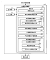
- FIG. 1 is a block diagram showing a functional configuration of the image processing apparatus according to Embodiment 1 of the present invention.
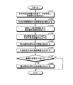
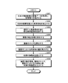
- FIG. 2 is a flowchart illustrating image processing performed by the image processing apparatus according to Embodiment 1 of the present invention.
- FIG. 3 is a diagram illustrating an example of a display mode of a plurality of representative images extracted in image processing performed by the image processing apparatus according to Embodiment 1 of the present invention.
- FIG. 4 is a diagram for explaining an example of a display mode when a representative image is selected from a plurality of representative images extracted in the image processing performed by the image processing apparatus according to Embodiment 1 of the present invention.
- FIG. 1 is a block diagram showing a functional configuration of the image processing apparatus according to Embodiment 1 of the present invention.
- FIG. 2 is a flowchart illustrating image processing performed by the image processing apparatus according to Embodiment 1 of the present invention.
- FIG. 3 is a diagram illustrating an example of a display mode of a pluralit
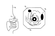
- FIG. 5 is a diagram illustrating an example of a display mode when a representative image is selected from a plurality of representative images extracted in the image processing performed by the image processing apparatus according to the first modification of the first embodiment of the present invention.
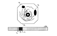
- FIG. 6 is a diagram illustrating an example of a display mode when a representative image is selected from a plurality of representative images extracted in image processing performed by the image processing apparatus according to the second modification of the first embodiment of the present invention.
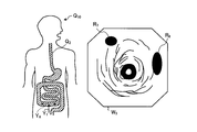
- FIG. 7 is a diagram for explaining an example of a display mode when a representative image is selected from a plurality of representative images extracted in the image processing performed by the image processing apparatus according to the third modification of the first embodiment of the present invention. .
- FIG. 6 is a diagram illustrating an example of a display mode when a representative image is selected from a plurality of representative images extracted in the image processing performed by the image processing apparatus according to the second modification of the first embodiment of the present invention.
- FIG. 7 is a diagram for explaining an example of a display mode when a representative image
- FIG. 8 is a diagram illustrating an example of a display mode of a plurality of representative images extracted in the image processing performed by the image processing apparatus according to the fourth modification of the first embodiment of the present invention.
- FIG. 9 is a block diagram showing a functional configuration of the image processing apparatus according to Embodiment 2 of the present invention.
- FIG. 10 is a flowchart illustrating image processing performed by the image processing apparatus according to Embodiment 2 of the present invention.
- FIG. 11 is a block diagram illustrating a functional configuration of the image processing apparatus according to the first modification of the second embodiment of the present invention.
- FIG. 12 is a block diagram showing a functional configuration of an image processing apparatus according to Modification 2 of Embodiment 2 of the present invention.
- FIG. 13 is a block diagram showing a functional configuration of an image processing apparatus according to Modification 3 of Embodiment 2 of the present invention.
- FIG. 14 is a block diagram showing a functional configuration of an image processing apparatus according to Embodiment 3 of the present invention.
- FIG. 15 is a flowchart illustrating image processing performed by the image processing apparatus according to the third embodiment of the present invention.
- FIG. 1 is a block diagram showing a functional configuration of the image processing apparatus according to Embodiment 1 of the present invention.
- An image processing apparatus 1 shown in FIG. 1 includes a calculation unit 2, a storage unit 3, and an input unit 4.
- the image processing apparatus 1 has a function of acquiring an in-vivo lumen image captured by a medical device such as a capsule endoscope or an endoscope and performing predetermined image processing.
- a medical device such as a capsule endoscope or an endoscope
- As the in-vivo lumen image a color image having pixel levels (pixel values) with respect to wavelength components of R (red), G (green), and B (blue) at each pixel position is used.
- the in-vivo lumen images are generated by being sequentially captured in time series and are sequentially input to the image processing apparatus 1.
- the image processing device 1 outputs the generated image and information to the display device 5 and displays various information on the display device 5.
- the display device 5 is realized by a display device such as an LCD or an EL display, and displays various screens including an in-vivo lumen image input from the image processing device 1.
- the calculation unit 2 includes an abnormality detection unit 21 that detects an abnormal region of the in-vivo lumen image continuously captured in time series, a similar abnormal interval setting unit 22 that sets a similar abnormal region including a similar abnormal region, The section information generation unit 23 that calculates section information related to the similar abnormal section, and the section information display control that outputs the section information calculated by the section information generation unit 23 to the display device 5 and performs display control of the section information on the display device 5.
- a representative image extracting unit 25 that extracts a representative in-vivo lumen image from the similar abnormal section as a representative image, a representative image extracted by the representative image extracting unit 25, and a representative image in the display device 5
- a representative image display control unit 26 that performs image display control.
- the abnormality detection unit 21 detects an abnormal region that is a region of interest to be noted in the image based on various feature amounts of the in-vivo lumen image.
- the abnormal area is an area where the property or state of the subject in the in-pipe image satisfies a predetermined condition.
- the region is such that the tissue properties or in-vivo state of the living body satisfies a predetermined condition. More specifically, for example, a region where the tissue properties of the living body such as ulcer, after, erosion, polyp, tumor, hemorrhage, redness, and villi are changed, and a state change in the living body such as bleeding occurs.
- an area etc. can be mentioned.
- an example in which an abnormal region is detected based on a color feature amount (color information) of an intraluminal image will be described.
- abnormal areas such as bleeding, redness, and vascular abnormalities show a specific color in red
- abnormal areas such as ulcers and after show a specific color in white. Therefore, the abnormality detection unit 21 uses each color component (R component, G component, B component) of the pixel value and a value that is secondarily calculated by a known conversion process based on these color components (for example, by YCbCr conversion).
- a region indicating a specific color in the in-vivo lumen image is detected.
- This region is defined as an abnormal region. More specifically, based on the color feature values of various abnormal areas collected in advance, an abnormal area discrimination standard (color range) is created in advance and recorded in the storage unit 3. Then, when detecting an abnormal region from the in-vivo lumen image, the discrimination criterion is read from the storage unit 3, and the color feature amount is calculated for each pixel constituting the in-vivo lumen image, and the color feature of each pixel is calculated. An abnormal region is detected from the in-vivo lumen image by comparing the amount with a discrimination criterion.
- region is not limited to the detection method mentioned above,
- region is applicable.
- a method based on a feature space distance with a representative color feature amount may be used.
- the abnormal region is detected using the color feature amount of each pixel constituting the in-vivo lumen image, but the in-vivo lumen image is divided into small regions based on edge information in the image.
- the abnormal region may be detected using the color feature amount in units of small regions.
- an abnormal region may be detected using a shape feature amount other than a color feature amount or a texture feature amount. *
- the similar abnormal section setting unit 22 sets a similar abnormal section including the same abnormal area based on the abnormal area detected by the abnormality detecting section 21. More specifically, the similar abnormal section setting unit 22 sets in-vivo lumen images that are continuous in time series among in-vivo lumen images including the abnormal area as in-vivo lumen image groups including the same abnormal area. Extracting and setting this in-vivo lumen image group as one similar abnormal section.
- the amount of change between images is obtained based on a normalized cross-correlation between abnormal images, a motion vector change amount, a change amount of a pixel value (luminance value or G component value), and the change amount is a predetermined value.
- the following abnormal image group may be extracted as an abnormal image group including the same abnormal region.
- a difference value between abnormal images of the shape feature amount (area, circularity, etc.) and color feature amount (color ratio, hue, etc.) of the abnormal region is calculated, and the difference value is equal to or less than a predetermined value set in advance.
- a certain abnormal image group may be extracted as an abnormal image group including the same abnormal region.
- the section information generation unit 23 includes a length information generation unit 231 that generates length information of similar abnormal sections.
- the length information generation unit 231 calculates the number of picked-up images 231a for calculating the number of picked-up images in the similar abnormal section, the shooting time calculation unit 231b for calculating the shooting time of the similar abnormal section, and the movement distance of the similar abnormal section.
- a movement distance calculation unit 231c In the first embodiment, the length information generated by the length information generation unit 231 corresponds to information related to the similar abnormal section.
- the number of captured images calculation unit 231a calculates the number of captured images by counting the in-vivo lumen images in the similar abnormal section.
- the imaging time calculation unit 231b calculates the imaging time required for imaging the in-vivo lumen image in the similar abnormal section. This imaging time corresponds to the movement time of the imaging unit of the medical device in the similar abnormal section.
- the movement distance calculation unit 231c calculates the movement distance of the medical device in the similar abnormal section. Specifically, the movement distance calculation unit 231c calculates a motion vector by performing template matching and estimates the movement distance from the motion vector, as disclosed in, for example, Japanese Patent Application Laid-Open No. 2006-334297. Use. Note that the movement distance calculation unit 231c may calculate the movement distance from the estimation result by using a method of estimating the in-vivo position based on the reception status of radio waves or the detection result of a sensor or the like in the medical device. In this in-vivo position estimation method, the in-vivo position between the start position and the end position of the similar abnormal section is estimated, and the difference is calculated to calculate the movement distance.
- the section information display control unit 24 refers to the storage unit 3, and for the similar abnormal section corresponding to the selected representative image, the number-of-images calculation unit 231 a
- the number of captured images which is the length information generated by the time calculation unit 231b and the movement distance calculation unit 231c, the imaging time, and the movement distance are acquired and output to the display device 5.
- the representative image extraction unit 25 extracts the in-vivo lumen image group including the same abnormal region from the in-vivo lumen image including the abnormal region detected by the abnormality detection unit 21, and the extracted in-vivo lumen image group The representative image is extracted based on at least one of the importance of each abnormal region and the visibility of each abnormal region.
- the representative image extraction unit 25, from each of the in-vivo lumen image group including the same abnormal region, the in-vivo lumen image including the abnormal region with high importance, or the in-vivo lumen image with high visibility of the abnormal region Are extracted as representative images.
- the degree of importance of an abnormal region refers to the relationship between a detection target and each abnormal region in diagnosis for an in-vivo lumen image, in other words, the likelihood of detection, and the stronger this relationship (the detection target It seems to be important. For example, when a bleeding source is a detection target, the degree of importance of the abnormal region is determined to be higher as the detected abnormal region is more likely to be a bleeding source. If one similar abnormal section is set, the representative image display control unit 26 extracts at least one representative image from the similar abnormal section, and if a plurality of different similar abnormal sections are set, At least one representative image is extracted from each abnormal section.
- the method for extracting the representative image is not particularly limited.
- the first in-vivo lumen image in time series order of each in-vivo lumen image group may be extracted as a representative image.
- the abnormal region shows a specific color of red tone
- the in vivo lumen image with a strong red color of the abnormal region is preferentially extracted as a representative image
- an in-vivo lumen image with a strong white color in the abnormal region is preferentially extracted as a representative image.
- an in-vivo lumen image having a large area of the abnormal region or an in-vivo lumen image in which the position of the abnormal region is close to the center may be preferentially extracted as a representative image.
- the representative image display control unit 26 outputs the representative image extracted by the representative image extraction unit 25 to the external display device 5 and causes the display device 5 to display the output representative image.
- the arithmetic unit 2 is realized by using a general-purpose processor such as a CPU (Central Processing Unit) having arithmetic and control functions, or a dedicated integrated circuit such as an ASIC (Application Specific Integrated Circuit) or FPGA (Field Programmable Gate Array).
- a general-purpose processor such as a CPU (Central Processing Unit) having arithmetic and control functions
- ASIC Application Specific Integrated Circuit
- FPGA Field Programmable Gate Array
- the storage unit 3 stores in-vivo lumen image data to be processed and various information necessary for processing.
- the storage unit 3 includes various IC memories such as ROM (Read Only Memory) or RAM (Random Access Memory), a hard disk connected with a built-in or data communication terminal, or an information recording device such as a CD-ROM and its reading device. Realized.
- the storage unit 3 operates the image processing device 1 in addition to the image data of the in-vivo lumen image acquired by the image processing device 1, and causes the image processing device 1 to execute various functions.
- the data used during the execution of is stored.
- the storage unit 3 stores an operation program according to the first embodiment, various parameters used when performing abnormal region detection processing, and the like.
- Various programs such as an image processing program stored in the storage unit 3 can be recorded on a computer-readable recording medium.
- the recording of various programs in the storage unit 3 or the recording medium may be performed when the computer or the recording medium is shipped as a product, or may be performed by downloading via a communication network.
- the communication network here is realized by, for example, an existing public line network, LAN (Local Area Network), WAN (Wide Area Network), etc., and may be wired or wireless.
- the input unit 4 receives an input of a signal according to an external operation, and inputs the received signal to the calculation unit 2.
- the input part 4 is implement
- the image processing apparatus 1 includes a display unit, a touch panel can be provided on the surface of the display panel and the touch panel can function as an input unit.
- the image processing apparatus 1 having the above configuration may be realized using a single computer or a plurality of computers. In the latter case, it is also possible to perform processing in cooperation with each other while transmitting and receiving data via a communication network.
- the computer here can be comprised by a general purpose personal computer, a server, etc., for example.
- the configuration of the medical device for inputting the in-vivo lumen image to the image processing device 1 is not particularly limited in the present invention.
- An example of the medical device is a capsule endoscope.
- the capsule endoscope is introduced into the subject by oral ingestion or the like, then moves inside the organ (gastrointestinal tract), and is finally discharged out of the subject. Meanwhile, the capsule endoscope performs imaging while moving inside the organ by the peristaltic motion of the organ, sequentially generates image signals, and the image processing apparatus 1 or the capsule endoscope and the image processing apparatus 1 Wirelessly transmitted to a relay device that relays between them.
- FIG. 2 is a flowchart illustrating image processing performed by the image processing apparatus according to Embodiment 1 of the present invention.
- the image processing apparatus 1 acquires image data of the in-vivo lumen image, writes it in the storage unit 3, and stores it (step S101).
- a plurality of in-vivo lumen images are input in time series.
- the storage unit 3 stores the input in-vivo lumen image in time series or in association with time series.
- the image processing apparatus 1 may acquire a biological lumen image by communicating with a device such as a capsule endoscope that captures a biological lumen image, or from a recording medium on which the biological lumen image is recorded. You may acquire by reading the data of a lumen image in a living body.
- the abnormality detection unit 21 sequentially reads out the image data of the in-vivo lumen images stored in the storage unit 3, and performs a process of detecting an abnormal region from each in-vivo lumen image. Specifically, the abnormality detection unit 21 reads out an abnormal region discrimination criterion recorded in advance in the storage unit 3, and compares the color feature amount of each pixel constituting each in-vivo lumen image with this discrimination criterion. Thus, the abnormal area is determined.
- the similar abnormal section setting unit 22 extracts from the abnormal area detected in step S102 as a group of in-vivo lumen images including a plurality of in-vivo lumen images including the same or similar abnormal area.
- a lumen image group is set as a similar abnormal section (step S103).
- the representative image extraction unit 25 determines from the in-vivo lumen image group extracted in step S103, an in-vivo lumen image having a high degree of importance of the abnormal region or an in-vivo tube having high visibility of the abnormal region. At least one cavity image is extracted as a representative image.
- the number of representative images to be extracted may be a constant (for example, one from each in-vivo lumen image group) or determined according to the number of in-vivo lumen images belonging to the in-vivo lumen image group. (For example, ⁇ times the number of in-vivo lumen images, 0 ⁇ ⁇ 1). In the latter case, when the number of representative images is less than one, at least one representative image is extracted.
- in-vivo lumen images satisfying a predetermined criterion for example, in-vivo lumen images having a color feature amount equal to or greater than a predetermined threshold
- a predetermined criterion for example, in-vivo lumen images having a color feature amount equal to or greater than a predetermined threshold
- the section information generation unit 23 generates length information of the similar abnormal section. Specifically, the section information generation unit 23 acquires the number of captured images, the imaging time, and the movement distance of the similar abnormal section calculated by the length information generation unit 231 and generates length information including these pieces of information. To do. After generating the length information of each similar abnormal section, the section information generating unit 23 stores the generated length information in the storage unit 3 in association with the similar abnormal section.
- step S106 the representative image display control unit 26 outputs the representative image extracted by the representative image extraction unit 25 in step S104 to the external display device 5, and causes the display device 5 to display the output representative image.
- FIG. 3 is a diagram illustrating an example of a display mode of a plurality of representative images extracted in image processing performed by the image processing apparatus according to Embodiment 1 of the present invention.
- a plurality of similar abnormal sections are set in step S103 and one representative image is extracted in each similar abnormal section, representative images W 1 to W 6 in the respective similar abnormal sections are displayed as shown in FIG. It is displayed on the device 5.
- the representative images W 1 to W 6 are in-vivo lumen images including mutually different abnormal regions R 1 to R 10 .
- step S107 the calculation unit 2 instructs a selection input for selecting any one of the plurality of representative images W 1 to W 6 that are signals received by the input unit 4 and displayed on the display device 5. It is determined whether or not a signal to be input is input.
- the calculation unit 2 proceeds to step S108.
- step S108 the calculation unit 2 determines the selected representative image based on the input signal, and outputs the determination result to the section information display control unit 24.
- the section information display control unit 24 acquires length information about the similar abnormal section corresponding to the selected representative image, and outputs it to the display device 5. Thereby, the length information is displayed on the display device 5 together with the representative image.
- FIG. 4 is a diagram for explaining an example of a display mode when a representative image is selected from a plurality of representative images extracted in the image processing performed by the image processing apparatus according to Embodiment 1 of the present invention.
- a selection frame S 1 indicating that the representative image W 5 is selected is displayed, and the representative image W a length information D 1 is captured with the number of images of the similar abnormal section corresponding to 5, the imaging time and distance are displayed.
- the user can confirm time-series information about the selected representative image.
- the section information generation unit 23 uses the number of captured images, the imaging time, and the moving distance as length information for the similar abnormal section set by the similar abnormal section setting unit 22.
- the section information display control unit 24 acquires the length information of the similar abnormal section corresponding to the selected representative image and outputs it to the display device 5.
- time-series information related to a region of interest in the representative image Can be displayed. Thereby, the user can confirm the representative image and the time-series information related to the representative image, and perform an efficient and highly accurate diagnosis.
- the length information generation unit 231 has been described as generating information regarding the number of captured images, imaging time, and moving distance. However, among the number of captured images, imaging time, and moving distance, If there is at least one piece of information, it is possible to confirm time-series information of similar sections to which the representative image belongs. That is, in the configuration of the first embodiment described above, it is sufficient if it has at least one of the number-of-images calculation unit 231a, the imaging time calculation unit 231b, and the movement distance calculation unit 231c.
- the selection frame S 1 as shown in FIG. 4 and the length information D 1 corresponding to the representative image are displayed. Not limited to this.
- Modifications 1 to 3 an example in which the display device 5 displays when a representative image is selected will be described.
- FIG. 5 is a diagram illustrating an example of a display mode when a representative image is selected from a plurality of representative images extracted in the image processing performed by the image processing apparatus according to the first modification of the first embodiment of the present invention. .
- step S 108 the display device 5 together with the selected representative image W 5 as shown in FIG. the capsule endoscope to view the locus Q 1 passing through.
- the locus Q 1 as the information regarding the representative image W 5 which is selected, the arrow Y 1 indicating the position of the representative image W 5 in the locus Q 1, dashed arrows indicate like abnormal section in which the representative image W 5 belongs Y R and is given.
- the section information display control unit 24 calculates the display position of the arrow Y 1 based on the trajectory information associated with the representative image W 5 .
- the section information display control unit 24 includes the number of picked-up images, the pick-up time and the moving distance, which are length information generated by the pick-up number calculating unit 231a, the pick-up time calculating unit 231b, and the moving distance calculating unit 231c, and the similar abnormal section.
- the start position and / or calculates the position information of the capsule endoscope in the body from the end position, by integrating the position information and length information to generate a dashed arrow Y R is the body position integrated information, the output To do.
- the display position and display range of the broken-line arrow Y R are calculated based on the trajectory information associated with each in-vivo lumen image at the start position and end position of the similar abnormal section including the representative image W 5. It may be.
- FIG. 6 is a diagram illustrating an example of a display mode when a representative image is selected from a plurality of representative images extracted in image processing performed by the image processing apparatus according to the second modification of the first embodiment of the present invention. .
- the display device 5 includes a plurality of images acquired by the medical device together with the selected representative image W 5 as shown in FIG.
- a color bar CB 1 in which the average colors of the in-vivo lumen images are arranged in time series is displayed.
- the color bar CB 1 shown as information regarding the representative image W 5 which is selected, the arrow Y 1 indicating the position of the representative image W 5 in the color bar CB 1, a similar abnormal section including the representative image W 5 A dashed arrow Y R is given.
- the section information display control unit 24 calculates the display position of the arrow Y 1 based on the average color position of the in-vivo lumen image that is the representative image W 5 .
- the section information display control unit 24 displays the display position of the broken-line arrow Y R based on the average color position of each in-vivo lumen image at the start position and end position of the similar abnormal section to which the representative image W 5 belongs. And the display range is calculated.
- FIG. 7 is a diagram for explaining an example of a display mode when a representative image is selected from a plurality of representative images extracted in the image processing performed by the image processing apparatus according to the third modification of the first embodiment of the present invention. .
- step S 108 the display device 5 together with the selected representative image W 5 as shown in FIG.
- An organ map Q 2 of the subject Q 10 into which the capsule endoscope is introduced is displayed.
- the organ map Q 2 the dashed line indicated as information relating to the representative image W 5 which is selected, the arrow Y 1 indicating the position of the representative image W 5 in the locus Q 1, a similar abnormal section including the representative image W 5
- An arrow Y R is given.
- the section information display control unit 24 calculates the display position of the arrow Y 1 based on the trajectory information associated with the representative image W 5 and the movement distance of the capsule endoscope.
- section information display control unit 24 uses a broken line arrow based on the trajectory information associated with each in-vivo lumen image at the start position and end position of the similar abnormal section to which the representative image W 5 belongs, and the movement distance. calculating a display position and display range of the Y R.
- the length information D 1 according to the first embodiment may be further displayed.
- FIG. 8 is a diagram illustrating an example of a display mode of a plurality of representative images extracted in the image processing performed by the image processing apparatus according to the fourth modification of the first embodiment of the present invention.
- the extracted representative images W 1 to W 6 are arranged on the basis of preset conditions, and are displayed on the display device 5 in this arrangement order. Examples of conditions include time series and the number of abnormal areas.
- a plurality of extracted representative images may be displayed as a moving image.
- the fourth modification when the user selects and inputs the representative images W 1 to W 6 that are sequentially displayed by switching the images, the representative image displayed at the time of the selection input is selected, and the selected representative is displayed. for images, length information D 1 or the like as shown in FIG. 4 is displayed.
- FIG. 9 is a block diagram showing a functional configuration of the image processing apparatus according to Embodiment 2 of the present invention.
- An image processing apparatus 1A shown in FIG. 1 includes a calculation unit 2A, a storage unit 3, and an input unit 4.
- the image processing apparatus 1 ⁇ / b> A outputs the generated image and information to the display device 5 and displays various information on the display device 5.
- the calculation unit 2A includes an abnormality detection unit 21 that detects an abnormal region of an in-vivo lumen image continuously captured in time series, a similar abnormal interval setting unit 22 that sets a similar abnormal region including a similar abnormal region, A section information generation unit 23A that calculates information related to a similar abnormal section, a section information display control unit 24A that outputs section information calculated by the section information generation unit 23A, and a representative in vivo lumen image from the similar abnormal section A representative image extraction unit 25 that extracts images, a representative image display control unit 26 that outputs a representative image extracted by the representative image extraction unit 25, and an abnormality type determination unit 27 that determines the type of abnormality.
- the section information generation unit 23A has a similar image group extraction unit 232 that extracts a living body lumen image that has not been selected as a representative image among a plurality of living body lumen images belonging to a similar abnormal section.
- the similar image group extracting unit 232 includes a non-representative image extracting unit 232a that extracts all the in-vivo lumen images belonging to the similar abnormal section in chronological order from the similar abnormal section.
- the in-vivo lumen image extracted by the similar image group extraction unit 232 corresponds to information related to the similar abnormal section.
- the abnormality type determination unit 27 determines whether or not there is a shape abnormality determination unit 271 that determines whether or not there is a shape abnormality, a color abnormality determination unit 272 that determines whether or not there is a color abnormality, and whether or not it is a texture abnormality. And a texture abnormality determination unit 273.
- the shape abnormality determination unit 271 determines whether or not the detected abnormal region is a shape abnormality based on whether or not the region has a circular shape. Specifically, the shape abnormality determination unit 271 uses a known Sobel filter, Laplacian filter, or the like to determine the gradient strength of pixel values (luminance (Y) component pixel values, G component pixel values, etc.) in the in-vivo lumen image. Use to calculate. The shape abnormality determination unit 271 calculates a correlation value between the gradient strength calculated by the shape abnormality determination unit 271 and a circular model created in advance, and the correlation value is equal to or greater than a preset threshold value.
- the detected abnormal region is abnormal in shape.
- the second embodiment has been described as determining whether or not the detected abnormal region is abnormal in shape by pattern matching with a circular model created in advance, the present invention is not limited to this. However, since it is only necessary to detect a circular region from the in-vivo lumen image, it may be detected by, for example, known Hough transform, RANSAC, DPM (Deformable Part Model), ELSD (Ellipse and Line Segment Detector), or the like.
- the color abnormality determination unit 272 determines whether or not the detected abnormal region is a color abnormality based on the specific colors of white and red. Specifically, from an image having color abnormalities and other abnormalities collected in advance, each pixel value of each color component (R component, G component, B component) and secondarily by a known conversion process based on them. Calculates the calculated value, color difference (YCbCr conversion), hue, saturation (HSI conversion), color ratio (G / R, B / G), etc., and based on the calculated values, criteria for determining color abnormality Is set in advance.
- the color abnormality determination unit 272 determines whether or not each pixel has a color abnormality based on the color feature amount of each pixel to be processed and a predetermined criterion.
- the color abnormality is detected based on the criterion set in advance.
- the present invention is not limited to this, and an abnormal region having a specific color is detected from the in-vivo lumen image.
- the detection may be performed by a method based on a feature amount spatial distance with a typical color feature amount.
- color abnormalities using color feature values in small region units It may be determined whether or not.
- the texture abnormality determination unit 273 determines that an abnormal region where the pattern on the mucous membrane surface is uneven is a texture abnormality. Specifically, texture feature values such as LBP (Local Binary Pattern) feature values and dispersion of pixel values of each color component (R component, G component, B component) are calculated from images with texture anomalies prepared in advance. Then, a texture abnormality determination criterion is determined based on the calculated feature amount. Then, for each divided area obtained by dividing the in-vivo lumen image into rectangles, it is determined whether or not each divided area is texture abnormal based on the calculated texture feature amount and the above-described determination criterion.
- LBP Local Binary Pattern
- the description will be made on the assumption that the determination result of the shape abnormality determination unit 271 is different from the determination results of the color abnormality determination unit 272 and the texture abnormality determination unit 273.
- the section information display control unit 24A outputs the in-vivo lumen image not selected as the representative image.
- the shape abnormality determination unit 271 determines that the representative image has a shape abnormality
- the section information display control unit 24A displays the in-vivo lumen image on the display device 5 with a high frame rate moving image.
- the section information display control unit 24A has a low frame rate (when the color abnormality determination unit 272 determines that the color abnormality is present and / or the texture abnormality determination unit 273 determines that the texture abnormality is present. It is displayed on the display device 5 as a still image of thinning display.
- An abnormal shape is easily mistaken for a mucosal fistula, and therefore needs to be confirmed in detail by continuous images.
- the color abnormality and the texture abnormality are easy to diagnose from a still image, they are quickly displayed on the still image in order to reduce the diagnosis time.
- FIG. 10 is a flowchart illustrating image processing performed by the image processing apparatus according to Embodiment 2 of the present invention.
- the image processing apparatus 1A acquires image data of the in-vivo lumen image, writes it in the storage unit 3, and stores it (step S201).
- an abnormal area is detected from each in-vivo lumen image (step S202), and a similar abnormal section is set from the detected abnormal area (step S202).
- S203 representative images are extracted from a plurality of in-vivo lumen images belonging to the set similar abnormal section (step S204).
- the section information generation unit 23A extracts an in-vivo lumen image not selected as a representative image from the similar abnormal section. Specifically, the non-representative image extraction unit 232a extracts an in-vivo lumen image belonging to the set similar abnormal section. The non-representative image extraction unit 232a may extract all of the in-vivo lumen images belonging to the similar abnormal section, or generate a plurality of in-vivo lumen images arranged in time series at predetermined intervals. A body lumen image may be extracted. The section information generation unit 23A outputs the extracted in-vivo lumen image as section information.
- the representative image display control unit 26 outputs the representative image extracted by the representative image extraction unit 25 in step S204 to the external display device 5, and causes the display device 5 to display the output representative image.
- the display device 5 for example, as shown in FIG. 3, representative images W 1 to W 6 in each similar abnormal section are displayed on the display device 5.
- the abnormality type determination unit 27 determines the type of abnormality whether the detected abnormal region is a shape abnormality, a color abnormality, or a texture abnormality. Based on the determination results of the shape abnormality determination unit 271, the color abnormality determination unit 272, and the texture abnormality determination unit 273, the abnormality type determination unit 27 detects an abnormal region included in the in-vivo lumen image belonging to the set similar abnormality section. Determine the type of abnormality.
- the section information generation unit 23A sets the frame rate based on the determination result corresponding to the similar abnormal section.
- the section information generating unit 23A sets the frame rate of the in-vivo lumen image in the similar abnormal section to which the representative image belongs to a high frame rate. To do.
- the section information generation unit 23A belongs to this representative image when the color abnormality determination unit 272 determines that the color abnormality is present and / or when the texture abnormality determination unit 273 determines that the texture abnormality is present.
- the frame rate of the in-vivo lumen image in the similar abnormal section is set to a low frame rate. When the low frame rate is set, a plurality of in-vivo lumen images belonging to the similar abnormal section are displayed on the display device 5 by thinning display.
- step S209 the calculation unit 2 instructs a selection input for selecting any one of the plurality of representative images W 1 to W 6 that are signals from the input unit 4 and displayed on the display device 5. It is determined whether or not a signal is input.
- the calculation unit 2 proceeds to step S210.
- step S210 the calculation unit 2 determines the selected representative image based on the input signal, and outputs the determination result to the section information display control unit 24A.
- the section information display control unit 24A acquires the in-vivo lumen image extracted by the non-representative image extraction unit 232a and the frame rate information related to the similar abnormal section for the similar abnormal section corresponding to the selected representative image. And output to the display device 5.
- the abnormality type determination unit 27 determines the type of abnormality in the abnormal region of the in-vivo lumen image group belonging to the similar abnormality section, and the section information generation unit 23A
- the section information display control unit 24A selects the selected representative image and The in-vivo lumen image other than the representative image extracted by the non-representative image extraction unit 232a and the frame rate set in the similar abnormal section are output to the display device 5.
- the abnormality type determination unit 27 determines the type of the abnormal region existing in the in-vivo lumen image group belonging to the similar abnormality section, and the section information generation unit 23A displays the abnormality. Since the frame rate of the similar abnormal section is set based on the determination result of the type determination unit 27, the display mode of the in-vivo lumen image can be changed according to the type of abnormality. Thereby, the user can perform a highly accurate diagnosis efficiently.
- the section information generation unit 23A has been described as changing the frame rate in accordance with the type of abnormality in the abnormal region.
- the in vivo lumen when the abnormal region is abnormal in shape The display interval of the image may be set shorter than the display interval of the in-vivo lumen image when the abnormal region is abnormal in color or texture.
- the type of abnormality is determined for all the similar abnormal sections. However, only the similar abnormal section to which the representative image selected and input belongs belongs to this abnormal abnormal section. The type may be determined. In this case, in step S207, when the representative image is selected in step S209, the abnormality type determination unit 27 determines the type of abnormality for the similar abnormal section to which the representative image belongs.
- the abnormality type determination unit 27 includes the shape abnormality determination unit 271, the color abnormality determination unit 272, and the texture abnormality determination unit 273, and sets the frame rate based on each determination result.
- the abnormality kind determination part 27 should just have any one of the shape abnormality determination part 271, the color abnormality determination part 272, and the texture abnormality determination part 273.
- the section information generation unit 23 ⁇ / b> A has a high frame rate when the shape abnormality determination unit 271 determines that the abnormal region is abnormal in shape.
- the abnormal shape determination unit 271 determines that the abnormal region is not abnormal in shape, the low frame rate may be set.
- FIG. 11 is a block diagram illustrating a functional configuration of the image processing apparatus according to the first modification of the second embodiment of the present invention.
- An image processing apparatus 1B shown in FIG. 1 includes a calculation unit 2B, a storage unit 3, and an input unit 4.
- the image processing device 1 ⁇ / b> B outputs the generated image and information to the display device 5 and causes the display device 5 to display various information.
- the calculation unit 2B includes an abnormality detection unit 21 that detects an abnormal region of an in-vivo lumen image continuously captured in time series, a similar abnormal interval setting unit 22 that sets a similar abnormal region including a similar abnormal region, It has section information generation part 23B which calculates information about similar abnormal section, section information display control part 24A which outputs section information which section information generation part 23B calculated, and abnormal kind judgment part 27 which judges the kind of abnormality .
- the section information generation unit 23B includes a similar image group extraction unit 232A that extracts an in-vivo lumen image that has not been selected as a representative image from a similar abnormal section.
- the similar image group extraction unit 232A includes an important image extraction unit 232b that preferentially extracts an important in-vivo lumen image group having a high malignancy from a similar abnormal section.
- the degree of malignancy here indicates the degree of malignancy of the tissue, is one of the indices set pathologically, and is a numerical value determined by quantitatively evaluating the degree of malignancy.
- the important image extraction unit 232b preferentially extracts an important in-vivo lumen image having a high malignancy among a plurality of in-vivo lumen images belonging to the similar abnormal section. Specifically, from pre-prepared images with various malignancy levels, pixel values of each color component (R component, G component, B component) and secondarily by a known conversion process based on them. Calculate the calculated value, color difference (YCbCr conversion), hue, saturation (HSI conversion), color ratio (G / R, B / G), etc., and use the calculated values as criteria for determining the malignancy. Set it.
- the important image extraction unit 232b determines the malignancy of the in-vivo lumen images belonging to the similar abnormal section based on a predetermined criterion, and preferentially extracts the in-vivo lumen images having a high malignancy. To do.
- “preferentially extracting” means that a predetermined number of in-vivo lumen images are extracted in descending order of malignancy.
- the important image extraction unit 232b extracts an important in-vivo lumen image having a high malignancy among a plurality of in-vivo lumen images belonging to the similar abnormal section.
- the device 5 displays an in-vivo lumen image determined to have high malignancy. Thereby, the user can perform an efficient and reliable diagnosis.
- FIG. 12 is a block diagram showing a functional configuration of an image processing apparatus according to Modification 2 of Embodiment 2 of the present invention.
- An image processing apparatus 1 ⁇ / b> C illustrated in FIG. 1 includes a calculation unit 2 ⁇ / b> C, a storage unit 3, and an input unit 4.
- the image processing apparatus 1 ⁇ / b> C outputs the generated image and information to the display device 5 and displays various information on the display device 5.
- the calculation unit 2C includes an abnormality detection unit 21 that detects an abnormal region of the in-vivo lumen image continuously captured in time series, a similar abnormal interval setting unit 22 that sets a similar abnormal region including a similar abnormal region, It has section information generation part 23C which calculates information about similar abnormal section, section information display control part 24A which outputs section information which section information generation part 23C calculated, and abnormal kind judgment part 27 which judges the kind of abnormality .
- the section information generation unit 23C includes a similar image group extraction unit 232B that extracts an in-vivo lumen image that has not been selected as a representative image from a similar abnormal section.
- the similar image group extraction unit 232B includes a high-visibility image extraction unit 232c that preferentially extracts a highly visible in-vivo lumen image group from the similar abnormal section.
- the visibility here indicates the degree of appearance of a subject or the like in an image, and is a numerical value determined by quantitatively evaluating the appearance.
- the high-visibility image extraction unit 232c preferentially extracts a group of in-vivo lumen images that are highly visible and easily diagnosed from among a plurality of in-vivo lumen images that belong to the similar abnormal section. Specifically, from various images with various levels of visibility prepared in advance, the pixel values of each color component (R component, G component, B component) and secondarily by a known conversion process based on them. Calculate the calculated value, color difference (YCbCr conversion), hue, saturation (HSI conversion), color ratio (G / R, B / G), etc., and determine the visibility criteria based on the calculated values. Make a decision. The high-visibility image extraction unit 232c determines the visibility of the in-vivo lumen image belonging to the similar abnormal section based on a predetermined criterion, and preferentially selects the in-vivo lumen image with high visibility. To extract.
- the high-visibility image extracting unit 232c extracts a highly visible in-vivo lumen image from among a plurality of in-vivo lumen images belonging to the similar abnormal section.
- the device 5 displays an in vivo lumen image determined to have high visibility. Thereby, the user can confirm the representative image and a highly visible in-vivo lumen image different from the representative image, and can perform an efficient and highly accurate diagnosis.
- FIG. 13 is a block diagram showing a functional configuration of an image processing apparatus according to Modification 3 of Embodiment 2 of the present invention.
- An image processing apparatus 1D shown in FIG. 1 includes a calculation unit 2D, a storage unit 3, and an input unit 4.
- the image processing device 1 ⁇ / b> D outputs the generated image and information to the display device 5 and displays various information on the display device 5.
- the calculation unit 2D includes an abnormality detection unit 21 that detects an abnormal region of an in-vivo lumen image continuously captured in time series, a similar abnormal interval setting unit 22 that sets a similar abnormal region including a similar abnormal region, It has section information generation part 23D which calculates information about similar abnormal section, section information display control part 24A which outputs section information which section information generation part 23D calculated, and abnormal kind judgment part 27 which judges the kind of abnormality .
- the section information generation unit 23D includes a similar image group extraction unit 232C that extracts a living body lumen image that has not been selected as a representative image from a similar abnormal section.
- the similar image group extraction unit 232C includes a dissimilar image extraction unit 232d that extracts a group of in-vivo lumen images that are not similar to the representative image from the similar abnormal section.
- the dissimilar image extraction unit 232d extracts an in-vivo lumen image that is not similar to a representative in-vivo lumen image from the similar abnormal section. Specifically, normalized cross-correlation, motion vector change amount, pixel value (luminance (Y) component pixel value, G component) of the in-vivo lumen image that was not selected as the representative image from the representative image and similar abnormal sections And the in-vivo lumen image in which the calculated amount of change is equal to or greater than a predetermined value is preferentially extracted.
- the dissimilar image extraction unit 232d extracts, for example, in-vivo lumen images in order from the larger difference between the change amount and the predetermined value.
- the dissimilar image extracting unit 232d extracts a living body lumen image having a low similarity to the representative image from among a plurality of living body lumen images belonging to the similar abnormal section. Therefore, in addition to the representative image, an in-vivo lumen image that is different from the representative image is displayed on the display device 5. Thereby, the user can perform an efficient and highly accurate diagnosis.
- in-vivo lumen images other than the representative image by combining at least two of the non-representative image extraction unit 232a, the important image extraction unit 232b, the high-visibility image extraction unit 232c, and the dissimilar image extraction unit 232d. May be extracted.
- the important image extraction unit 232b determines the malignancy of each of the plurality of in-vivo lumen images extracted by the non-representative image extraction unit 232a. A determination is made and an in-vivo lumen image that satisfies the determination criteria is extracted.
- FIG. 14 is a block diagram showing a functional configuration of an image processing apparatus according to Embodiment 3 of the present invention.
- An image processing apparatus 1E shown in FIG. 1 includes a calculation unit 2E, a storage unit 3, and an input unit 4.
- the image processing device 1E outputs the generated image and information to the display device 5 and causes the display device 5 to display various information.
- the calculation unit 2E includes an abnormality detection unit 21 that detects an abnormal region of the in-vivo lumen image continuously captured in time series, a similar abnormal interval setting unit 22 that sets a similar abnormal region including a similar abnormal region, A section information generating unit 23E and a section information generating unit 23E generate information on the similar abnormal section as movements of the intestinal tract in the similar abnormal section, the size, the amount of contents in the intestinal tract, and the degree of damage of the mucous membrane as information on the similar abnormal section.
- a section information display control unit 24B that outputs the calculated section information.
- “content” in the third embodiment refers to residues and blood remaining in the intestinal tract.
- the abnormal region detected by the abnormality detector 21 detects a region including the intestinal tract.
- the section information generation unit 23E includes an intestinal movement information calculation unit 233 that calculates intestinal movement information, an intestinal size calculation unit 234 that calculates the size of the intestinal tract, and a content amount calculation unit 235 that calculates the amount of content in the intestinal tract. And a mucous membrane damage degree calculation unit 236 for calculating the degree of mucosal damage.
- the intestinal movement information calculation unit 233 calculates intestinal movement information. Specifically, the intestinal tract movement information calculation unit 233 is a medical calculation calculated from the image movement calculated based on the normalized phase correlation of the in-vivo lumen image group in the similar abnormal section, the motion vector, and the detection result of the sensor or the like. Information indicating the movement of the intestinal tract is calculated based on the movement of the apparatus.
- the intestinal tract size calculation unit 234 calculates the size of the intestinal tract. Specifically, the intestinal tract size calculation unit 234 calculates depth information (pixel value of R component, automatic gain control (AGC) value, etc.) and arc region (arc extraction by Hough transform etc.) in the image. The size of the intestinal tract is calculated from the size.
- depth information pixel value of R component, automatic gain control (AGC) value, etc.
- arc region arc extraction by Hough transform etc.
- the content amount calculation unit 235 includes a residue amount calculation unit 235a that calculates the amount of residue and a bleeding amount calculation unit 235b that calculates the amount of bleeding.
- the residue amount calculation unit 235a and the bleeding amount calculation unit 235b respectively calculate the amount of residue and the amount of bleeding in the in-vivo lumen image based on the color feature amount and the texture feature amount.
- the content amount calculation unit 235 may calculate the amount of bubbles in the in-vivo lumen image in addition to the residue and bleeding.
- the mucosa damage degree calculation unit 236 calculates the damage degree of the mucous membrane. Specifically, the mucous membrane damage degree calculation unit 236 calculates the degree of mucosal damage based on the presence or absence of villi or the presence or absence of mucosal abnormality detected by image processing. The mucosa damage degree calculation unit 236 calculates the damage degree of the mucous membrane by comparing the amount per unit area of the villi with a medically determined criterion. The amount of villi per unit area can be calculated by extracting a high-frequency component after performing frequency analysis of the in-vivo lumen image.
- the section information display control unit 24B displays the intestinal movement information, the intestinal tract size, the amount of contents in the abnormal region in the intestinal tract and the degree of damage of the mucous membrane generated by the section information generating unit 23E for each similar abnormal section. Is output to the display device 5.
- FIG. 15 is a flowchart illustrating image processing performed by the image processing apparatus according to the third embodiment of the present invention.
- the image processing apparatus 1E acquires image data of the in-vivo lumen image, writes it in the storage unit 3, and stores it (step S301).
- an abnormal area is detected from each in-vivo lumen image (step S302), and a similar abnormal section is set from the detected abnormal area (step S302). S303).
- the section information generation unit 23E calculates information relating to the intestinal tract for each set similar abnormal section.
- the intestinal tract motion information calculation unit 233 calculates intestinal tract motion information.
- the intestinal tract size calculation unit 234 calculates the size of the intestinal tract.
- the content amount calculation unit 235 calculates the amount of residue and the amount of bleeding.
- the mucosal damage degree calculation unit 236 calculates the mucosal damage degree.
- the section information display control unit 24B acquires information on the intestinal tract for each similar abnormal section generated by the section information generation unit 23E, and outputs the acquired information to the display device 5.
- the display device 5 displays intestinal information related to the similar abnormal section for each similar abnormal section.
- the section information generation unit 23E calculates information related to the intestinal tract with respect to the similar abnormal section set by the similar abnormal section setting unit 22, and the section information display control unit 24B.
- the information related to the intestinal tract generated by the section information generation unit 23E is acquired and output to the display device 5, a series of images acquired by imaging the lumen of the living body in time series order
- the display device 5 When displaying information related to the intestinal tract, it is possible to display time-series information related to the intestinal tract shown in the in-vivo lumen image.
- the user can confirm the time-sequential information regarding the intestinal tract reflected in each in-vivo lumen image and perform a highly accurate diagnosis.
- the image processing apparatus, the operation method of the image processing apparatus, and the operation program of the image processing apparatus according to the present invention use a series of images acquired by imaging the inside of the lumen of a living body in time series. This is useful for making an efficient and highly accurate diagnosis.
Landscapes
- Engineering & Computer Science (AREA)
- Physics & Mathematics (AREA)
- Health & Medical Sciences (AREA)
- Life Sciences & Earth Sciences (AREA)
- Computer Vision & Pattern Recognition (AREA)
- General Physics & Mathematics (AREA)
- Theoretical Computer Science (AREA)
- Surgery (AREA)
- Radiology & Medical Imaging (AREA)
- General Health & Medical Sciences (AREA)
- Medical Informatics (AREA)
- Nuclear Medicine, Radiotherapy & Molecular Imaging (AREA)
- Molecular Biology (AREA)
- Animal Behavior & Ethology (AREA)
- Optics & Photonics (AREA)
- Biomedical Technology (AREA)
- Heart & Thoracic Surgery (AREA)
- Biophysics (AREA)
- Veterinary Medicine (AREA)
- Pathology (AREA)
- Public Health (AREA)
- Quality & Reliability (AREA)
- Geometry (AREA)
- Multimedia (AREA)
- Endoscopes (AREA)
- Closed-Circuit Television Systems (AREA)
Abstract
La présente invention concerne un dispositif de traitement d'images comportant une unité de détection d'anomalie (21) pour détecter chaque région anormale parmi une pluralité d'images de lumière in vivo capturées par un dispositif médical inséré dans un organisme vivant, une unité de réglage de section d'anomalie similaire (22) pour définir une section d'anomalie similaire comprenant une région anormale similaire, une unité de génération d'informations de section (23) pour générer des informations relatives à la section d'anomalie similaire, et une unité de commande d'affichage d'informations de section (24) pour amener un dispositif d'affichage à afficher les informations relatives à la section d'anomalie similaire.
Priority Applications (3)
| Application Number | Priority Date | Filing Date | Title |
|---|---|---|---|
| JP2018518028A JP6741759B2 (ja) | 2016-05-19 | 2016-05-19 | 画像処理装置、画像処理装置の作動方法及び画像処理装置の作動プログラム |
| PCT/JP2016/064933 WO2017199408A1 (fr) | 2016-05-19 | 2016-05-19 | Dispositif de traitement d'images, procédé de fonctionnement pour dispositif de traitement d'images et programme de fonctionnement pour dispositif de traitement d'images |
| US16/193,057 US10776921B2 (en) | 2016-05-19 | 2018-11-16 | Image processing apparatus, operation method for image processing apparatus, and recording medium |
Applications Claiming Priority (1)
| Application Number | Priority Date | Filing Date | Title |
|---|---|---|---|
| PCT/JP2016/064933 WO2017199408A1 (fr) | 2016-05-19 | 2016-05-19 | Dispositif de traitement d'images, procédé de fonctionnement pour dispositif de traitement d'images et programme de fonctionnement pour dispositif de traitement d'images |
Related Child Applications (1)
| Application Number | Title | Priority Date | Filing Date |
|---|---|---|---|
| US16/193,057 Continuation US10776921B2 (en) | 2016-05-19 | 2018-11-16 | Image processing apparatus, operation method for image processing apparatus, and recording medium |
Publications (1)
| Publication Number | Publication Date |
|---|---|
| WO2017199408A1 true WO2017199408A1 (fr) | 2017-11-23 |
Family
ID=60325075
Family Applications (1)
| Application Number | Title | Priority Date | Filing Date |
|---|---|---|---|
| PCT/JP2016/064933 Ceased WO2017199408A1 (fr) | 2016-05-19 | 2016-05-19 | Dispositif de traitement d'images, procédé de fonctionnement pour dispositif de traitement d'images et programme de fonctionnement pour dispositif de traitement d'images |
Country Status (3)
| Country | Link |
|---|---|
| US (1) | US10776921B2 (fr) |
| JP (1) | JP6741759B2 (fr) |
| WO (1) | WO2017199408A1 (fr) |
Cited By (5)
| Publication number | Priority date | Publication date | Assignee | Title |
|---|---|---|---|---|
| JP2021045337A (ja) * | 2019-09-18 | 2021-03-25 | 富士フイルム株式会社 | 医用画像処理装置、プロセッサ装置、内視鏡システム、医用画像処理方法、及びプログラム |
| CN113094537A (zh) * | 2021-04-07 | 2021-07-09 | 南京云格信息技术有限公司 | 一种基于fpga的图像处理系统 |
| JPWO2022059668A1 (fr) * | 2020-09-15 | 2022-03-24 | ||
| WO2023286199A1 (fr) * | 2021-07-14 | 2023-01-19 | アイリス株式会社 | Dispositif, programme et procédé de traitement, et système de traitement |
| JP2023530710A (ja) * | 2020-06-19 | 2023-07-19 | ザ ジェネラル ホスピタル コーポレイション | 近赤外自己蛍光イメージングシステム及び方法 |
Families Citing this family (8)
| Publication number | Priority date | Publication date | Assignee | Title |
|---|---|---|---|---|
| JP6749473B2 (ja) * | 2017-03-30 | 2020-09-02 | 富士フイルム株式会社 | 内視鏡システム及びその作動方法 |
| KR101898580B1 (ko) * | 2018-01-22 | 2018-09-13 | 주식회사 뷰노 | 영상의 열람을 지원하는 방법 및 이를 이용한 장치 |
| CN112584738B (zh) * | 2018-08-30 | 2024-04-23 | 奥林巴斯株式会社 | 记录装置、图像观察装置、观察系统、观察系统的控制方法及存储介质 |
| JP7629310B2 (ja) * | 2021-01-29 | 2025-02-13 | 富士フイルム株式会社 | 情報処理装置、情報処理方法及び情報処理プログラム |
| CN113112448A (zh) * | 2021-02-25 | 2021-07-13 | 惠州华阳通用电子有限公司 | 一种显示画面检测方法及存储介质 |
| JP7768802B2 (ja) * | 2021-09-08 | 2025-11-12 | 株式会社エビデント | 検査画像表示方法、検査支援装置、検査支援システム、およびプログラム |
| US12602793B2 (en) * | 2022-06-30 | 2026-04-14 | Lenovo Global Technology (United States) Inc. | Systems and methods for predicting object location within images and for analyzing the images in the predicted location for object tracking |
| CN116912440A (zh) * | 2023-07-12 | 2023-10-20 | 同济大学 | 一种针对地下弱光弱纹理环境下的结构语义地图构建方法 |
Citations (5)
| Publication number | Priority date | Publication date | Assignee | Title |
|---|---|---|---|---|
| JP2006320650A (ja) * | 2005-05-20 | 2006-11-30 | Olympus Medical Systems Corp | 画像表示装置 |
| JP2008061704A (ja) * | 2006-09-05 | 2008-03-21 | Olympus Medical Systems Corp | 画像表示装置 |
| JP2009028407A (ja) * | 2007-07-30 | 2009-02-12 | Olympus Corp | 画像解析装置および画像解析プログラム |
| JP5568196B1 (ja) * | 2012-10-18 | 2014-08-06 | オリンパスメディカルシステムズ株式会社 | 画像処理装置及び画像処理方法 |
| JP2016063868A (ja) * | 2014-09-22 | 2016-04-28 | オリンパス株式会社 | 画像表示装置、画像表示方法、及び画像表示プログラム |
Family Cites Families (4)
| Publication number | Priority date | Publication date | Assignee | Title |
|---|---|---|---|---|
| JP4716794B2 (ja) | 2005-06-06 | 2011-07-06 | オリンパスメディカルシステムズ株式会社 | 画像表示装置 |
| US8900124B2 (en) | 2006-08-03 | 2014-12-02 | Olympus Medical Systems Corp. | Image display device |
| WO2008149674A1 (fr) | 2007-06-05 | 2008-12-11 | Olympus Corporation | Dispositif de traitement d'image, programme de traitement d'image et procédé de traitement d'image |
| JP5220705B2 (ja) | 2009-07-23 | 2013-06-26 | オリンパス株式会社 | 画像処理装置、画像処理プログラムおよび画像処理方法 |
-
2016
- 2016-05-19 WO PCT/JP2016/064933 patent/WO2017199408A1/fr not_active Ceased
- 2016-05-19 JP JP2018518028A patent/JP6741759B2/ja active Active
-
2018
- 2018-11-16 US US16/193,057 patent/US10776921B2/en active Active
Patent Citations (5)
| Publication number | Priority date | Publication date | Assignee | Title |
|---|---|---|---|---|
| JP2006320650A (ja) * | 2005-05-20 | 2006-11-30 | Olympus Medical Systems Corp | 画像表示装置 |
| JP2008061704A (ja) * | 2006-09-05 | 2008-03-21 | Olympus Medical Systems Corp | 画像表示装置 |
| JP2009028407A (ja) * | 2007-07-30 | 2009-02-12 | Olympus Corp | 画像解析装置および画像解析プログラム |
| JP5568196B1 (ja) * | 2012-10-18 | 2014-08-06 | オリンパスメディカルシステムズ株式会社 | 画像処理装置及び画像処理方法 |
| JP2016063868A (ja) * | 2014-09-22 | 2016-04-28 | オリンパス株式会社 | 画像表示装置、画像表示方法、及び画像表示プログラム |
Cited By (11)
| Publication number | Priority date | Publication date | Assignee | Title |
|---|---|---|---|---|
| JP2021045337A (ja) * | 2019-09-18 | 2021-03-25 | 富士フイルム株式会社 | 医用画像処理装置、プロセッサ装置、内視鏡システム、医用画像処理方法、及びプログラム |
| US12362061B2 (en) | 2019-09-18 | 2025-07-15 | Fujifilm Corporation | Medical image processing device, processor device, endoscope system, medical image processing method, and program |
| JP2023530710A (ja) * | 2020-06-19 | 2023-07-19 | ザ ジェネラル ホスピタル コーポレイション | 近赤外自己蛍光イメージングシステム及び方法 |
| JP7743447B2 (ja) | 2020-06-19 | 2025-09-24 | ザ ジェネラル ホスピタル コーポレイション | 近赤外自己蛍光イメージングシステム及び方法 |
| JPWO2022059668A1 (fr) * | 2020-09-15 | 2022-03-24 | ||
| WO2022059668A1 (fr) * | 2020-09-15 | 2022-03-24 | 富士フイルム株式会社 | Dispositif de traitement d'image médicale et procédé pour faire fonctionner un dispositif de traitement d'image médicale, et programme pour dispositif de traitement d'image médicale |
| JP7495511B2 (ja) | 2020-09-15 | 2024-06-04 | 富士フイルム株式会社 | 医用画像処理装置及び医用画像処理装置の作動方法並びに医用画像処理装置用プログラム |
| CN113094537A (zh) * | 2021-04-07 | 2021-07-09 | 南京云格信息技术有限公司 | 一种基于fpga的图像处理系统 |
| CN113094537B (zh) * | 2021-04-07 | 2024-01-02 | 南京云格信息技术有限公司 | 一种基于fpga的图像处理系统 |
| WO2023286199A1 (fr) * | 2021-07-14 | 2023-01-19 | アイリス株式会社 | Dispositif, programme et procédé de traitement, et système de traitement |
| JPWO2023286199A1 (fr) * | 2021-07-14 | 2023-01-19 |
Also Published As
| Publication number | Publication date |
|---|---|
| JP6741759B2 (ja) | 2020-08-19 |
| JPWO2017199408A1 (ja) | 2019-04-04 |
| US20190087959A1 (en) | 2019-03-21 |
| US10776921B2 (en) | 2020-09-15 |
Similar Documents
| Publication | Publication Date | Title |
|---|---|---|
| JP6741759B2 (ja) | 画像処理装置、画像処理装置の作動方法及び画像処理装置の作動プログラム | |
| US8502861B2 (en) | Image display apparatus | |
| US11170498B2 (en) | Image processing device, image processing method, and image processing program for detecting specific region from image captured by endoscope designated as detection target image in response to determining that operator's action in not predetermined action | |
| JP5147308B2 (ja) | 画像抽出装置および画像抽出プログラム | |
| JP7413585B2 (ja) | 医用画像処理装置、作動方法、プログラム、及び記録媒体、診断支援装置並びに内視鏡システム | |
| JP5305850B2 (ja) | 画像処理装置、画像処理プログラムおよび画像処理方法 | |
| JP4902735B2 (ja) | 医療用画像処理装置及び医療用画像処理方法 | |
| JP6552601B2 (ja) | 画像処理装置、画像処理装置の作動方法および画像処理プログラム | |
| JP2010158308A (ja) | 画像処理装置、画像処理方法および画像処理プログラム | |
| JP2010187756A (ja) | 画像処理装置、画像処理方法および画像処理プログラム | |
| JPWO2018105063A1 (ja) | 画像処理装置 | |
| US12213654B2 (en) | Phase identification of endoscopy procedures | |
| US20200090548A1 (en) | Image processing apparatus, image processing method, and computer-readable recording medium | |
| WO2018020558A1 (fr) | Dispositif, procédé et programme de traitement d'image | |
| JP2023181214A (ja) | 情報処理装置、情報処理方法、及びコンピュータプログラム | |
| EP3875021A1 (fr) | Appareil de traitement d'image médicale, procédé de traitement d'image médicale et appareil d'assistance au diagnostic | |
| US20190298159A1 (en) | Image processing device, operation method, and computer readable recording medium | |
| KR20150049585A (ko) | 용종 검출 장치 및 그 동작방법 | |
| US20240257348A1 (en) | Endoscopic image processing device, endoscopic image processing method, and endoscope system | |
| JP6840263B2 (ja) | 内視鏡システム及びプログラム | |
| CN100411576C (zh) | 内窥镜插入方向检测装置、内窥镜插入方向检测系统及内窥镜插入方向检测方法 | |
| CN105118070A (zh) | 基于时间序列的无线胶囊内窥镜视频中的出血段定位方法 | |
| CN101257835B (zh) | 图像显示装置 | |
| JP2009077800A (ja) | 画像処理装置および画像処理プログラム | |
| US20250378556A1 (en) | Endoscopic examination assistance device, endoscopic examination system, processing method, and storage medium |
Legal Events
| Date | Code | Title | Description |
|---|---|---|---|
| ENP | Entry into the national phase |
Ref document number: 2018518028 Country of ref document: JP Kind code of ref document: A |
|
| NENP | Non-entry into the national phase |
Ref country code: DE |
|
| 121 | Ep: the epo has been informed by wipo that ep was designated in this application |
Ref document number: 16902427 Country of ref document: EP Kind code of ref document: A1 |
|
| 122 | Ep: pct application non-entry in european phase |
Ref document number: 16902427 Country of ref document: EP Kind code of ref document: A1 |