WO2017199426A1 - Dispositif de porte d'ascenseur - Google Patents
Dispositif de porte d'ascenseur Download PDFInfo
- Publication number
- WO2017199426A1 WO2017199426A1 PCT/JP2016/065015 JP2016065015W WO2017199426A1 WO 2017199426 A1 WO2017199426 A1 WO 2017199426A1 JP 2016065015 W JP2016065015 W JP 2016065015W WO 2017199426 A1 WO2017199426 A1 WO 2017199426A1
- Authority
- WO
- WIPO (PCT)
- Prior art keywords
- floor
- car
- door
- failure
- failure detection
- Prior art date
- Legal status (The legal status is an assumption and is not a legal conclusion. Google has not performed a legal analysis and makes no representation as to the accuracy of the status listed.)
- Ceased
Links
Images





Classifications
-
- B—PERFORMING OPERATIONS; TRANSPORTING
- B66—HOISTING; LIFTING; HAULING
- B66B—ELEVATORS; ESCALATORS OR MOVING WALKWAYS
- B66B5/00—Applications of checking, fault-correcting, or safety devices in elevators
- B66B5/02—Applications of checking, fault-correcting, or safety devices in elevators responsive to abnormal operating conditions
-
- B—PERFORMING OPERATIONS; TRANSPORTING
- B66—HOISTING; LIFTING; HAULING
- B66B—ELEVATORS; ESCALATORS OR MOVING WALKWAYS
- B66B13/00—Doors, gates, or other apparatus controlling access to, or exit from, cages or lift well landings
- B66B13/24—Safety devices in passenger lifts, not otherwise provided for, for preventing trapping of passengers
- B66B13/26—Safety devices in passenger lifts, not otherwise provided for, for preventing trapping of passengers between closing doors
-
- B—PERFORMING OPERATIONS; TRANSPORTING
- B66—HOISTING; LIFTING; HAULING
- B66B—ELEVATORS; ESCALATORS OR MOVING WALKWAYS
- B66B13/00—Doors, gates, or other apparatus controlling access to, or exit from, cages or lift well landings
- B66B13/02—Door or gate operation
- B66B13/06—Door or gate operation of sliding doors
- B66B13/08—Door or gate operation of sliding doors guided for horizontal movement
-
- B—PERFORMING OPERATIONS; TRANSPORTING
- B66—HOISTING; LIFTING; HAULING
- B66B—ELEVATORS; ESCALATORS OR MOVING WALKWAYS
- B66B13/00—Doors, gates, or other apparatus controlling access to, or exit from, cages or lift well landings
- B66B13/02—Door or gate operation
- B66B13/14—Control systems or devices
-
- B—PERFORMING OPERATIONS; TRANSPORTING
- B66—HOISTING; LIFTING; HAULING
- B66B—ELEVATORS; ESCALATORS OR MOVING WALKWAYS
- B66B13/00—Doors, gates, or other apparatus controlling access to, or exit from, cages or lift well landings
- B66B13/22—Operation of door or gate contacts
-
- E—FIXED CONSTRUCTIONS
- E05—LOCKS; KEYS; WINDOW OR DOOR FITTINGS; SAFES
- E05Y—INDEXING SCHEME ASSOCIATED WITH SUBCLASSES E05D AND E05F, RELATING TO CONSTRUCTION ELEMENTS, ELECTRIC CONTROL, POWER SUPPLY, POWER SIGNAL OR TRANSMISSION, USER INTERFACES, MOUNTING OR COUPLING, DETAILS, ACCESSORIES, AUXILIARY OPERATIONS NOT OTHERWISE PROVIDED FOR, APPLICATION THEREOF
- E05Y2900/00—Application of doors, windows, wings or fittings thereof
- E05Y2900/10—Application of doors, windows, wings or fittings thereof for buildings or parts thereof
- E05Y2900/104—Application of doors, windows, wings or fittings thereof for buildings or parts thereof for elevators
Definitions
- the present invention relates to an elevator door device, and more particularly to an elevator door device capable of detecting a failure of a safety shoe provided at the tip of an elevator car door.
- the safety device detects that an obstacle such as an elevator user or user's baggage has touched the tip of the car door while the car door is being closed, and before the obstacle is pinched by the car door.
- the car door and the landing door are reversed in the door opening direction.
- a safety shoe is known as such a safety device.
- the safety shoe is provided on the side of the car door on the landing side so that a part of the safety shoe protrudes from the tip of the car door.
- the safety shoe is provided in the vertical direction over the upper and lower sides of the car door.
- an operational failure may occur in the shoe switch. For example, even if there are no obstacles in contact with the safety shoe, it may be erroneously detected as if the safety shoe has moved, and the car door and the landing door may be repeatedly reversed. obtain.
- an operation failure is referred to as an on failure.
- Patent Documents 1 to 3 Examples of conventional failure detection devices that detect a failure of a safety device include the following Patent Documents 1 to 3.
- Patent Document 1 describes an on-failure detection method.
- the shoe switch that detects the movement amount of the safety shoe is configured by a normally closed contact. Therefore, when the door open button is not pressed and the door close command is turned on when the door is fully open, the shoe switch should be closed if it is normal. However, if the shoe switch is open, it is determined that the safety shoe is on.
- Patent Document 2 describes an off-fault detection method.
- the protrusion part is attached to the safety shoe.
- the protruding portion is provided to face the door stop portion of the car door.
- the safety shoe is moved by the protrusion, and the internal contact of the shoe switch is opened. For this reason, even when the shoe is fully closed, if the internal contact of the shoe switch is in a closed state, it is determined that the safety shoe is off.
- Patent Document 3 proposes that an electromagnet device for retracting the safety shoe is provided, and the safety shoe is retracted by the control of the electromagnet device to detect an operation failure of the safety shoe during the door closing operation. Yes.
- a shoe switch can be turned on / off at an arbitrary timing by using an electromagnet device.
- JP-A-5-193879 JP 2007-182303 A Japanese Patent Laid-Open No. 61-277484
- Patent Document 3 since the safety shoe can be operated arbitrarily, it is possible to detect the on failure and the off failure of the safety shoe when the safety shoe is fully closed. However, it is necessary to install an electromagnet device for operating the safety shoe and a control device for the electromagnet device, and there is a problem that the cost increases.
- the present invention has been made in order to solve the above-described problems, and has a simple configuration, can reduce costs, and can detect off-failure detection and on-failure detection of a safety shoe when fully closed.
- the purpose is to obtain an elevator door device.
- the present invention provides a car door provided at an entrance of an elevator car, a safety shoe provided at a front end portion in the closing direction of the car door, and movable in an opening / closing direction of the car door, and provided in the car door.
- the safety shoe is provided at a door switch of the car for detecting that the safety shoe has moved a predetermined distance in the opening direction of the car door, and detects that the car door is in a fully closed position.
- a failure detection vane connected to the safety shoe, and at least one of the elevator landings, and the failure detection vane when the car door is fully closed.
- a failure detection roller for moving the safety shoe in the opening direction of the car door by the predetermined distance, and the elevator When the car has landed at one landing, the full-close recognition switch sets the car door to the fully-closed position based on the detection result of the full-close recognition switch and the detection result of the shoe switch.
- the presence or absence of an operation failure of the safety shoe is detected by determining whether the shoe switch has detected the movement of the safety shoe by the failure detection roller at a certain distance. It is an elevator door device provided with the failure determination part to determine.
- each floor of the building where the elevator is installed is divided into an off failure detection floor and an on failure detection floor. Then, off failure detection is performed on the off failure detection floor, and on failure detection is performed on the on failure detection floor.
- the elevator door device according to the embodiment of the present invention it is possible to detect the safety shoe on-fault only by adding simple members (see reference numerals 28 and 29) to the car and the off-fault detection floor. The detection of the off-failure can be performed with the door fully closed. As described above, since the failure detection is performed in the fully closed state of the door, the safety shoe is not pushed in artificially, so that erroneous detection due to an artificial factor does not occur.
- FIG. 1 to 7 are views showing an elevator door device according to Embodiment 1 of the present invention.
- 1 is a front view showing a configuration of an elevator car door according to Embodiment 1.
- FIG. 2 is a side view of the car door of FIG.
- FIG. 2 is a side view showing the car door shown in FIG. 1 in the direction of arrow A in FIG.
- FIG. 3 is a front view showing a mechanism for detecting a pinched door in the elevator door device according to the first embodiment.
- FIG. 4 is a side view showing the configuration of the off-failure detection floor according to the first embodiment.
- FIG. 5 is a front view showing an off-fault detection mechanism in the off-fault detection floor according to the first embodiment.
- FIG. 6 is a front view showing an on-failure detection mechanism in the on-failure detection floor according to the first embodiment.
- FIG. 7 is a flowchart showing a flow of a failure detection process for the elevator door device according to the first
- Figure 1 shows the car doorway.
- the car doorway is an opening of the elevator car.
- the elevator car is arranged in a hoistway and is loaded with users and the like to move up and down.
- a car door panel 1 is provided at the car doorway.
- the car door panel 1 can be opened and closed in the horizontal direction.
- the horizontal direction is the X-axis direction.
- the arrow B in FIG. 1 shows the door closing direction.
- a car door hanger 2 is attached to the upper end of the car door panel 1.
- One or more car door rollers 3 are rotatably mounted on the upper part of the car door hanger 2. In FIG. 1, two car door rollers 3 are provided, but the number of car door rollers 3 is not limited to this.
- a car girder 4 above the car doorway.
- a car door rail 5 is attached to the car girder 4 along the opening / closing direction of the car door panel 1, that is, in the horizontal direction.
- a car door roller 3 is engaged with the upper end of the car door rail 5.
- the car door panel 1 is suspended by a car door rail 5 via a car door hanger 2 and a car door roller 3.
- the car door roller 3 is guided by the car door rail 5 and rolls, so that the car door panel 1 opens and closes the car doorway.
- a car door shoe 6 is attached to the lower end of the car door panel 1.
- a car door sill 7 is attached to the lower part of the car doorway.
- a groove is formed in the car door sill 7.
- the car door shoe 6 is fitted in the groove of the car door sill 7 and moves while being guided by the groove.
- the grooves of the car door shoe 6 and the car door sill 7 prevent the car door panel 1 from moving in the depth direction (Z-axis direction).
- the members 1 to 7 provided at the car doorway constitute a “car door” provided at the doorway of the elevator car.
- FIG. 2 is a side view of the car doorway in FIG. 1 as viewed from the direction of arrow A in FIG. 1, that is, from the door stop side.
- FIG. 2 also shows the landing doorway.
- the structure of the landing doorway is the same as that of the car doorway described above. That is, members 8 to 14 respectively corresponding to members 1 to 7 provided at the car entrance are provided at the landing entrance.
- the members 8 to 14 provided at the landing entrance / exit constitute a “landing door” provided at the landing entrance / exit.
- the front view of the landing doorway is omitted, since it is the same as the structure of the car doorway, please refer to FIG. 1 together with FIG. Hereinafter, the members 8 to 14 will be described.
- a landing door panel 8 is provided at the landing entrance.
- the landing door panel 8 can be opened and closed in the horizontal direction.
- the number of landing door panels 8 is the same as the number of car door panels 1.
- a landing door hanger 9 is attached to the upper end of the landing door panel 8. Further, one or more landing door rollers 10 are rotatably attached to the upper portion of the landing door hanger 9. In FIG. 2, two landing door rollers 10 are provided.
- a landing girder 11 is provided above the landing entrance.
- a landing door rail 12 is attached to the landing beam 11 along the opening / closing direction of the landing door panel 8, that is, in the horizontal direction.
- a landing door roller 10 is rotatably engaged with the upper end of the landing door rail 12.
- the landing door panel 8 is suspended by a landing door rail 12 via a landing door hanger 9 and a landing door roller 10.
- the landing door roller 10 is guided by the landing door rail 12 and rolls, so that the landing door panel 8 opens and closes the landing doorway.
- a landing door shoe 13 is attached to the lower end of the landing door panel 8.
- a landing door sill 14 is attached to the lower part of the landing doorway. Grooves are formed in the landing door sill 14. The landing door shoe 13 is fitted in the groove of the landing door sill 14, and moves while being guided by the groove. The grooves of the landing door shoe 13 and the landing door sill 14 prevent the landing door panel 8 from moving in the depth direction (Z-axis direction).
- the opening / closing operation of the car door panel 1 is performed by a door driving device disposed above the door rail 5 of the car girder 4.
- the door driving device has a door motor 15.
- the door driving device is provided only on the car door side, and is not provided on the landing door side.
- the door motor 15 is provided on one side of the car girder 4 in the horizontal direction.
- the door motor 15 is provided on the right side of the car girder 4 in the horizontal direction.
- a drive wheel 16 is fixed to the rotating shaft of the door motor 15.
- a follower wheel 17 is rotatably mounted on the other side of the car girder 4 in the horizontal direction. That is, in FIG. 1, the follower wheel 17 is provided on the left side of the car girder 4 in the horizontal direction.
- the driven vehicle 17 is provided corresponding to the driving vehicle 16.
- the driven vehicle 17 and the driving vehicle 16 are installed at the same height.
- An endless toothed belt 18 is wound around the driving wheel 16 and the driven wheel 17.
- the teeth are formed on the inner side of the toothed belt 18 by providing irregularities at equal intervals.
- the driving wheel 16 and the driven wheel 17 are provided with irregularities for engaging with these teeth.
- the teeth of the toothed belt 18 mesh with the irregularities of the driving wheel 16 and the driven wheel 17, and the rotational drive of the door motor 15 is transmitted to the circulating movement of the toothed belt 18.
- This mechanism is called a winding transmission mechanism.
- the door drive device of the elevator which concerns on Embodiment 1 comprises the door drive device of the winding transmission mechanism.
- a locking member 19 is attached to the upper end of the car door hanger 2 of the car door panel 1.
- the locking member 19 is locked to the lower side of the toothed belt 18. Accordingly, the toothed belt 18 and the car door panel 1 operate in conjunction with each other via the locking member 19.
- the rotational drive of the door motor 15 in both forward and reverse directions is converted into a circular movement of the toothed belt 18 in both directions. Accordingly, when the door motor 15 rotates, the toothed belt 18 circulates and moves accordingly, and as a result, the car door panel 1 moves horizontally and the car doorway is opened and closed.
- a pair of stoppers 20 are provided on the car girder 4.
- One of these stoppers 20 is provided at each of the horizontal ends of the car girder 4.
- the stopper 20 restricts the car door panel 1 from moving beyond the fully open position and the fully closed position. Therefore, these stoppers 20 are arranged so that the end of the car door hanger 2 abuts against the stopper 20 when the door panel 1 is in the fully open state and the fully closed state.
- a fully closed recognition switch 21 is attached at a position above the car door hanger 2.
- the fully closed recognition switch 21 has a U-shaped cross section.
- a shielding plate 22 is attached to the upper end of the car door hanger 2.
- the outer shape of the shielding plate 22 is complementary to the U-shaped inner shape of the fully closed recognition switch 21.
- a light emitting element and a light receiving element are provided to face each other.
- the fully closed recognition switch 21 detects that the car door panel 1 is not fully closed when light is received by the light receiving element.
- the shielding plate 22 is positioned inside the U-shape of the fully closed recognition switch 21, the light emitted from the light emitting element is shielded by the shielding plate 22 and is not received by the light receiving element.
- the fully closed recognition switch 21 detects that the car door panel 1 is fully closed when no light is received by the light receiving element.
- the fully-closed recognition switch 21 outputs a fully-closed signal when detecting that the shielding plate 22 is positioned inside the U-shape. That is, the fully closed recognition switch 21 constitutes a fully closed detection unit that detects that the car door panel 1 is in the fully closed position.
- the door driving device is provided only on the car door side and not on the landing door side. More specifically, members corresponding to the above members 16 to 19 provided on the car entrance side are not provided on the landing entrance side.
- the landing door panel 8 is also driven by the door driving device provided on the car door panel 1 side. That is, the landing door panel 8 is opened and closed in synchronization with the car door panel 1 by being engaged with the car door panel 1 by the engaging member.
- the engaging member is composed of an engaging vane 23 and an engaging roller 24 shown in FIG.
- the engagement vane 23 is attached to the car door panel 1.
- the engagement roller 24 is attached to the landing door panel 8.
- a safety shoe 25 is provided at the front end of the car door panel 1 in the door closing direction in the vertical direction (Y-axis direction in FIG. 1).
- the safety shoe 25 is provided over almost the entire length of the car door panel 1.
- the safety shoe 25 is arranged such that its tip end protrudes from the tip end portion of the car door panel 1 toward the door stop side of the car by a predetermined distance.
- a link 26 is rotatably provided on the side surface of the car door panel 1 on the landing side.
- the safety shoe 25 is supported by a link 26 so as to be able to advance and retreat a predetermined distance in the opening / closing direction of the car door panel 1.
- a shoe switch 27 is provided on the side of the car door panel 1 on the landing side.
- the shoe switch 27 detects that the safety shoe 25 has moved by a distance set in advance in the door opening direction with respect to the car door panel 1.
- the shoe switch 27 is provided with a detector.
- the detector of the shoe switch 27 is engaged with the link 26.
- the shoe switch 27 is configured such that the internal contact is turned on or off depending on the position of the detector.
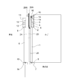
- a failure detection vane 28 is connected to the lower end of the safety shoe 25. As shown in FIG. 2, the failure detection vane 28 is installed so as to pass through a gap between the car door sill 7 and the landing door sill 14. Therefore, when the car moves up and down, the failure detection vane 28 does not come into contact with each device provided on the landing side.
- FIG. 4 is a side view illustrating the lowest floor of the building from the door-to-door direction.
- a failure detection roller 29 is installed on the lowermost floor at the lower part of the landing so as to protrude into the hoistway.
- the failure detection roller 29 is installed so as to come into contact with the failure detection vane 28 on the car side when the car has landed on the lowest floor and the door is fully closed.
- FIG. 4 shows a state where the failure detection roller 29 and the failure detection vane 28 are in contact with each other.
- the floor on which the failure detection roller 29 is attached is referred to as an “off failure detection floor”. That is, in Embodiment 1, the lowest floor of a building is an off-failure detection floor.
- an off-fault detection mechanism in the off-fault detection floor of the elevator door device according to Embodiment 1 will be described with reference to FIG.
- the elevator has landed on the lowest floor and the door is fully closed.
- the fully closed recognition switch 21 detects that the door is in the fully closed state.
- the failure detection vane 28 contacts the failure detection roller 29.
- the failure detection vane 28 is attached to the safety shoe 25 as described above.
- the safety shoe 25 is moved in the door opening direction as indicated by reference numeral (13). Be energized by. At this time, if normal, the safety shoe 25 moves in the door opening direction with respect to the car door panel 1 and turns on the shoe switch 27 via the link 26, as indicated by reference numeral (14). On the other hand, if the shoe switch 27 is not turned on, it means that the shoe switch is off. Therefore, when the car is landing on the lowest floor and the shoe switch 27 is in the off state when the door is in the fully closed state, it can be determined that the shoe switch is in an off failure.
- the failure detection roller 29 is attached to the lower part of the landing
- the failure detection roller 29 and the failure detection vane 28 are moved when the car passes the floor. Since the contact causes abnormal noise and damage, the off-fault detection floor can only be set to the lowest floor.
- the failure detection roller 29 is not attached to the lower landing of the floor other than the lowest floor. Therefore, the structure of floors other than the lowest floor is the same as FIG. 1, as shown in FIG.
- the floor where the failure detection roller 29 is not attached is referred to as an “on failure detection floor”. That is, in Embodiment 1, each floor other than the lowest floor of the building is an on-failure detection floor.
- FIG. 6 it is assumed that the elevator is landing on a floor other than the lowest floor and the door is in a fully closed state.
- the shielding plate 22 shields the fully closed recognition switch 21, so that the fully closed recognition switch 21 detects that the door is in the fully closed state as indicated by reference numeral (21). can do.
- the failure detection roller 29 is not provided. Therefore, the failure detection vane 28 does not contact the failure detection roller 29. Therefore, if it is normal, the safety shoe 25 does not move in the door opening direction with respect to the car door panel 1 as indicated by reference numeral (23). Therefore, as indicated by reference numeral (24), the shoe switch 27 remains off. Therefore, if the car is landing on a floor other than the lowest floor and the shoe switch 27 is on when the door is fully closed, it is determined that the shoe switch is on. Can do.
- FIG. 7 shows a flow of processing for detecting an on failure and an off failure in the elevator door device according to the first embodiment.
- the elevator door device according to Embodiment 1 includes a control device 32 as shown in FIG.
- the failure determination unit 33 provided in the control device 32 performs the flow of FIG.
- the control device 32 is composed of, for example, a personal computer.
- the control device 32 includes an input device to which an external signal is input, a processor that performs arithmetic processing, a memory that stores various data and programs, and an output device that outputs a signal to the outside.
- the failure determination unit 33 is realized by the processor executing a program stored in the memory. A plurality of processors and a plurality of memories may cooperate to execute the function of the failure determination unit 33.
- the failure determination unit 33 receives information from the shoe switch 27, information from the fully closed recognition switch 21, and floor information from an elevator control panel (not shown). The failure determination unit 33 determines the presence or absence of an on failure and an off failure of the safety shoe based on these signals.
- the shoe switch 27 outputs an on signal when the shoe switch 27 is on, and outputs an off signal when the shoe switch 27 is off. Therefore, the information from the shoe switch 27 is one of an on signal and an off signal.
- the fully closed recognition switch 21 outputs an ON signal when the car door panel 1 is in a fully closed state, and outputs nothing or an OFF signal when the car door panel 1 is not fully closed.
- the information from the fully closed recognition switch 21 is a signal indicating whether or not the car door panel 1 is fully closed.
- the floor signal from the elevator control panel is information indicating the floor number at which the car is currently stopped.
- the elevator control panel is a device that controls the operation of the car, and is a device provided in a machine room provided in the upper part of the hoistway.
- the failure determination unit 33 stores in advance a table in the memory that determines whether each floor is an on-failure detection floor or an off-failure detection floor. Therefore, when information on the stop floor of the car is input from the elevator control panel, it can be determined from the information whether the stop floor is an on-failure detection floor or an off-failure detection floor.
- the failure determination unit 33 determines whether the information from the shoe switch 27 is an on signal or an off signal in step S1. If it is an on signal, the process proceeds to step S7, and if it is an off signal, the process proceeds to step S2.
- step S2 the failure determination unit 33 determines whether the car door panel 1 is fully closed based on information from the fully closed recognition switch 21. If the car door panel 1 is fully closed, the process proceeds to step S4, and if not, the process proceeds to step S3.
- step S3 the failure determination unit 33 determines that the operation of the safety shoe is normal.
- step S4 the failure determination unit 33 determines whether the current car stop floor is an off-failure detection floor or an on-failure detection floor based on floor information from the elevator control panel. . If it is an off-failure detection floor, the process proceeds to step S5, and if it is an on-failure detection floor, the process proceeds to step S6.
- step S5 the failure determination unit 33 determines that the operation of the safety shoe is an off failure. As described above, since the failure detection roller 29 is provided on the off-failure detection floor, the shoe switch 27 should be turned on if the car door panel 1 is fully closed. Here, since the shoe switch 27 is in the OFF state, the failure determination unit 33 determines that the operation of the safety shoe is an OFF failure.
- step S6 the failure determination unit 33 determines that the operation of the safety shoe is normal. As described above, since the failure detection roller 29 is not provided on the on-failure detection floor, the shoe switch 27 should remain in the off state even when the car door panel 1 is fully closed. In this case, since the shoe switch 27 is in the OFF state, the failure determination unit 33 determines that the operation of the safety shoe is normal.
- Step S7 the failure determination unit 33 determines whether or not the car door panel 1 is fully closed based on information from the fully closed recognition switch 21. If the car door panel 1 is fully closed, the process proceeds to step S9; otherwise, the process proceeds to step S8.
- step S8 the failure determination unit 33 determines that there is an obstacle.
- step S9 the failure determination unit 33 determines whether the current car stop floor is the off-failure detection floor or the on-failure detection floor based on the floor information from the elevator control panel. . If it is an off-failure detection floor, the process proceeds to step S10, and if it is an on-failure detection floor, the process proceeds to step S11.
- step S10 the failure determination unit 33 determines that the operation of the safety shoe is normal. As described above, since the failure detection roller 29 is provided on the off-failure detection floor, the shoe switch 27 should be turned on when the car door panel 1 is fully closed. Then, since the shoe switch 27 is in the ON state, the failure determination unit 33 determines that the operation of the safety shoe is normal.
- step S11 the failure determination unit 33 determines that the operation of the safety shoe is an on failure. As described above, since the failure detection roller 29 is not provided on the on-failure detection floor, the shoe switch 27 should remain in the off state even when the car door panel 1 is fully closed. However, since the shoe switch 27 is in the ON state here, the failure determination unit 33 determines that the operation of the safety shoe is an ON failure.
- the safety shoe 25 Provided on the car door panel 1 and activated when the safety shoe 25 moves a predetermined distance in the opening direction of the car door, and provided at the entrance / exit of the car so that the car door is fully closed.
- the failure detection vane 28 connected to the safety shoe 25, and the elevator hall. The failure detection low moves the safety shoe 25 by a certain distance in the opening direction of the car door by contacting the failure detection vane 28.
- the failure determination unit 33 sets the floor of the hall where the failure detection roller 29 is installed as an off failure detection floor for detecting an off failure of the safety shoe 25, and the floor of the hall where the failure detection roller 29 is not installed.
- an on-failure detection floor for detecting an on-failure of the safety shoe 25 the presence or absence of an off-fault of the safety shoe 25 is detected when the car reaches the off-failure detection floor.
- each floor of a building is divided into an off failure detection floor and an on failure detection floor, a failure detection vane 28 is added to the car, and a failure detection roller 29 is added to the off failure detection floor.
- the failure determination unit 33 detects that the fully closed recognition switch 21 is in the fully closed position when the car reaches the off failure detection floor, and the shoe switch When 27 does not operate, it is determined that the safety shoe 25 has an off failure. That is, when the shoe switch 27 does not operate even though the failure detection roller 29 pushes the safety shoe 25 through the failure detection vane 28, it is an off-failure. An off-failure can be reliably detected.
- the failure determination unit 33 detects that the fully closed recognition switch 21 is in the fully closed position when the car has landed on the on failure detection floor, and the shoe switch When 27 is operated, it is determined that the safety shoe 25 is on-failure. That is, since the failure detection roller 29 is not provided on the on-failure detection floor, when the shoe switch 27 is activated even though the safety shoe 25 is not pushed, it is an on-failure, so that In addition, it is possible to reliably detect an on-failure.
- the on-failure detection is performed when the door is in the fully closed state, so that no erroneous detection is caused by human factors, and therefore the on-failure detection can be performed with high accuracy.
- the off-failure detection floor is set to the lowest floor. If the failure detection roller 29 is attached to the lower part of the landing other than the lowest floor, when the car passes through the floor, the failure detection roller 29 and the failure detection vane 28 come into contact with each other, and abnormal noise or damage occurs. However, in the first embodiment, since the failure detection roller 29 is provided on the lowest floor, no abnormal noise or damage occurs. In general, since there is an entrance of a building on the lowest floor, elevator users use the lowest floor most. Therefore, the frequency of the elevator landing on the lowest floor is higher than the frequency of landing on the other floors. In the first embodiment, only the lowest floor is an off-failure detection floor, and all other floors are on-failure detection floors.
- the number of on-failure detection floors is much larger than the number of off-failure detection floors. Too many.
- the lowest floor with a high landing frequency as the off-fault detection floor, it is possible to appropriately ensure the number of times that off-fault detection is performed.
- FIG. FIG. 8 is a side view showing a configuration of an elevator door device according to Embodiment 2 of the present invention.
- FIG. 8 shows the configuration of the off-failure detection floor.
- the off-fault detection floor is provided on the top floor of the building in FIG.
- the failure detection vane 28 ⁇ / b> A is installed above the upper end of the safety shoe 25.
- the failure detection vane 28A is arranged between the car door hanger 2 and the landing door hanger 9 so as not to contact them.
- a failure detection roller 29A is installed above the landing so as to protrude into the hoistway.
- the mechanism of failure detection is the same as in the first embodiment.
- the off-failure detection floor can be set as the top floor.
- the failure detection roller 29 cannot be installed at the lower part of the landing on the bottom floor, This is effective when there are few.
- the off-failure detection floor can be set to the top floor. For example, when the failure detection roller 29 cannot be installed at the lower part of the landing on the bottom floor, or to the bottom floor This is effective when the frequency of landing is low.
- Embodiment 3 FIG. It is also possible to set the off-fault detection floor to both the bottom floor and the top floor.
- the failure detection vane 28 is installed at the upper end of the safety shoe 25, and the failure detection vane 28A is installed at the lower end of the safety shoe 25.
- a failure detection roller 29 is installed at the lower part of the landing on the lowest floor so as to protrude into the hoistway, and a failure detection roller 29A is provided at the upper part of the landing on the uppermost floor so as to protrude into the hoistway. To do. Since the mechanism of failure detection is the same as in the first and second embodiments, the description thereof is omitted here.
- the same effect as in the first and second embodiments can be obtained.
- the off-fault detection floor can be set to the lowest floor and the top floor, the off-fault detection is performed even when the landing frequency on the bottom floor and the top floor is low. Since it can be performed on both the lowest floor and the top floor, it is possible to prevent the frequency of performing off-fault detection from being lowered.
Landscapes
- Engineering & Computer Science (AREA)
- Automation & Control Theory (AREA)
- Elevator Door Apparatuses (AREA)
- Maintenance And Inspection Apparatuses For Elevators (AREA)
Abstract
Priority Applications (6)
| Application Number | Priority Date | Filing Date | Title |
|---|---|---|---|
| US16/092,149 US10435275B2 (en) | 2016-05-20 | 2016-05-20 | Elevator door device |
| CN201680085714.4A CN109153543B (zh) | 2016-05-20 | 2016-05-20 | 电梯门装置 |
| PCT/JP2016/065015 WO2017199426A1 (fr) | 2016-05-20 | 2016-05-20 | Dispositif de porte d'ascenseur |
| JP2018518041A JP6537717B2 (ja) | 2016-05-20 | 2016-05-20 | エレベータのドア装置 |
| KR1020187033019A KR102047506B1 (ko) | 2016-05-20 | 2016-05-20 | 엘리베이터의 도어 장치 |
| DE112016006878.6T DE112016006878T5 (de) | 2016-05-20 | 2016-05-20 | Aufzugtürvorrichtung |
Applications Claiming Priority (1)
| Application Number | Priority Date | Filing Date | Title |
|---|---|---|---|
| PCT/JP2016/065015 WO2017199426A1 (fr) | 2016-05-20 | 2016-05-20 | Dispositif de porte d'ascenseur |
Publications (1)
| Publication Number | Publication Date |
|---|---|
| WO2017199426A1 true WO2017199426A1 (fr) | 2017-11-23 |
Family
ID=60325846
Family Applications (1)
| Application Number | Title | Priority Date | Filing Date |
|---|---|---|---|
| PCT/JP2016/065015 Ceased WO2017199426A1 (fr) | 2016-05-20 | 2016-05-20 | Dispositif de porte d'ascenseur |
Country Status (6)
| Country | Link |
|---|---|
| US (1) | US10435275B2 (fr) |
| JP (1) | JP6537717B2 (fr) |
| KR (1) | KR102047506B1 (fr) |
| CN (1) | CN109153543B (fr) |
| DE (1) | DE112016006878T5 (fr) |
| WO (1) | WO2017199426A1 (fr) |
Families Citing this family (2)
| Publication number | Priority date | Publication date | Assignee | Title |
|---|---|---|---|---|
| CN109153543B (zh) * | 2016-05-20 | 2020-08-04 | 三菱电机株式会社 | 电梯门装置 |
| WO2021075048A1 (fr) * | 2019-10-18 | 2021-04-22 | 三菱電機株式会社 | Appareil d'ascenseur et appareil de détection de position de porte associé |
Citations (5)
| Publication number | Priority date | Publication date | Assignee | Title |
|---|---|---|---|---|
| JP2007182303A (ja) * | 2006-01-06 | 2007-07-19 | Mitsubishi Electric Building Techno Service Co Ltd | エレベータの故障検出装置及びエレベータ装置の改修方法 |
| EP2345618A1 (fr) * | 2010-01-18 | 2011-07-20 | Inventio AG | Bordure de sécurité d'une porte de cabine |
| WO2012008035A1 (fr) * | 2010-07-15 | 2012-01-19 | 三菱電機株式会社 | Dispositif de commande de porte d'ascenseur |
| JP2013035677A (ja) * | 2011-08-10 | 2013-02-21 | Mitsubishi Electric Corp | エレベータかごの戸安全装置 |
| JP2016037374A (ja) * | 2014-08-08 | 2016-03-22 | 株式会社日立ビルシステム | セフティーシューの動作点検装置 |
Family Cites Families (14)
| Publication number | Priority date | Publication date | Assignee | Title |
|---|---|---|---|---|
| US1568461A (en) * | 1924-05-26 | 1926-01-05 | W A Sedwick | Safety automatic elevator-door equipment |
| US1655116A (en) * | 1926-03-13 | 1928-01-03 | Elevator Supplies Co Inc | Elevator-control apparatus |
| US1959042A (en) * | 1928-06-28 | 1934-05-15 | Otis Elevator Co | Gate opening and closing device |
| US2053799A (en) * | 1935-08-21 | 1936-09-08 | Howard F Mason | Elevator door opening apparatus |
| US3056470A (en) * | 1959-04-09 | 1962-10-02 | Schweiz Wagons Aufzuegefab | Control system for elevators |
| JPS5193879A (fr) | 1975-02-16 | 1976-08-17 | ||
| JPS61277584A (ja) | 1985-06-04 | 1986-12-08 | 日立エレベ−タサ−ビス株式会社 | エレベ−タ扉安全装置の動作確認装置 |
| JPH05193879A (ja) | 1992-01-22 | 1993-08-03 | Hitachi Building Syst Eng & Service Co Ltd | エレベーターの故障診断装置 |
| JPH08225279A (ja) * | 1995-02-23 | 1996-09-03 | Otis Elevator Co | エレベーターのドア安全装置 |
| JP4770277B2 (ja) | 2005-06-01 | 2011-09-14 | 三菱電機ビルテクノサービス株式会社 | エレベータの故障検出装置及びその故障検出方法並びにエレベータ装置の改修方法 |
| WO2008033118A1 (fr) * | 2006-09-12 | 2008-03-20 | Otis Elevator Company | Ensemble de porte incluant un capteur pour le contrôle du mouvement automatique de la portière |
| KR20100004987A (ko) * | 2007-03-16 | 2010-01-13 | 미쓰비시덴키 가부시키가이샤 | 엘리베이터의 출입구장치 |
| US8672098B2 (en) * | 2008-10-20 | 2014-03-18 | Fujitec Co., Ltd. | Elevator safety device with foreign matter detection using a light beam |
| CN109153543B (zh) * | 2016-05-20 | 2020-08-04 | 三菱电机株式会社 | 电梯门装置 |
-
2016
- 2016-05-20 CN CN201680085714.4A patent/CN109153543B/zh active Active
- 2016-05-20 DE DE112016006878.6T patent/DE112016006878T5/de not_active Ceased
- 2016-05-20 WO PCT/JP2016/065015 patent/WO2017199426A1/fr not_active Ceased
- 2016-05-20 KR KR1020187033019A patent/KR102047506B1/ko not_active Expired - Fee Related
- 2016-05-20 US US16/092,149 patent/US10435275B2/en active Active
- 2016-05-20 JP JP2018518041A patent/JP6537717B2/ja active Active
Patent Citations (5)
| Publication number | Priority date | Publication date | Assignee | Title |
|---|---|---|---|---|
| JP2007182303A (ja) * | 2006-01-06 | 2007-07-19 | Mitsubishi Electric Building Techno Service Co Ltd | エレベータの故障検出装置及びエレベータ装置の改修方法 |
| EP2345618A1 (fr) * | 2010-01-18 | 2011-07-20 | Inventio AG | Bordure de sécurité d'une porte de cabine |
| WO2012008035A1 (fr) * | 2010-07-15 | 2012-01-19 | 三菱電機株式会社 | Dispositif de commande de porte d'ascenseur |
| JP2013035677A (ja) * | 2011-08-10 | 2013-02-21 | Mitsubishi Electric Corp | エレベータかごの戸安全装置 |
| JP2016037374A (ja) * | 2014-08-08 | 2016-03-22 | 株式会社日立ビルシステム | セフティーシューの動作点検装置 |
Also Published As
| Publication number | Publication date |
|---|---|
| JP6537717B2 (ja) | 2019-07-03 |
| KR102047506B1 (ko) | 2019-11-22 |
| CN109153543A (zh) | 2019-01-04 |
| KR20180135932A (ko) | 2018-12-21 |
| US20190127183A1 (en) | 2019-05-02 |
| CN109153543B (zh) | 2020-08-04 |
| JPWO2017199426A1 (ja) | 2018-08-23 |
| DE112016006878T5 (de) | 2019-01-31 |
| US10435275B2 (en) | 2019-10-08 |
Similar Documents
| Publication | Publication Date | Title |
|---|---|---|
| JP5254566B2 (ja) | エレベータのドア装置 | |
| KR101865413B1 (ko) | 엘리베이터 카도어 개폐 장치 | |
| WO2017199426A1 (fr) | Dispositif de porte d'ascenseur | |
| JP2012153450A (ja) | エレベータの安全装置 | |
| JP6514625B2 (ja) | エレベータ装置及びエレベータ装置の制御方法 | |
| JP2015117090A (ja) | エレベータドアの制御装置 | |
| JP6195021B2 (ja) | エレベーターのドア装置 | |
| JP5436680B2 (ja) | エレベータ装置 | |
| JP5577636B2 (ja) | 出入口装置及びエレベータ装置 | |
| JP5683900B2 (ja) | エレベータ装置 | |
| JP2015101464A (ja) | エレベーターのかごドア装置 | |
| JP2013177211A (ja) | エレベータ出入口の安全装置 | |
| WO2012008035A1 (fr) | Dispositif de commande de porte d'ascenseur | |
| JP6351406B2 (ja) | エレベーターのドア制御装置 | |
| JP2014231421A (ja) | エレベータ用出入口装置 | |
| JP6079882B2 (ja) | エレベータのドア装置 | |
| WO2014199517A1 (fr) | Dispositif de commande de porte d'ascenseur | |
| JP3156432B2 (ja) | エレベーターのドア安全装置 | |
| JP5055969B2 (ja) | エレベータ装置及び制御方法 | |
| JP2010159121A (ja) | エレベータ | |
| JP2013124184A (ja) | エレベータ装置 |
Legal Events
| Date | Code | Title | Description |
|---|---|---|---|
| ENP | Entry into the national phase |
Ref document number: 2018518041 Country of ref document: JP Kind code of ref document: A |
|
| ENP | Entry into the national phase |
Ref document number: 20187033019 Country of ref document: KR Kind code of ref document: A |
|
| 121 | Ep: the epo has been informed by wipo that ep was designated in this application |
Ref document number: 16902445 Country of ref document: EP Kind code of ref document: A1 |
|
| 122 | Ep: pct application non-entry in european phase |
Ref document number: 16902445 Country of ref document: EP Kind code of ref document: A1 |