WO2017199511A1 - 水質分析計 - Google Patents
水質分析計 Download PDFInfo
- Publication number
- WO2017199511A1 WO2017199511A1 PCT/JP2017/006951 JP2017006951W WO2017199511A1 WO 2017199511 A1 WO2017199511 A1 WO 2017199511A1 JP 2017006951 W JP2017006951 W JP 2017006951W WO 2017199511 A1 WO2017199511 A1 WO 2017199511A1
- Authority
- WO
- WIPO (PCT)
- Prior art keywords
- light
- optical system
- wavelength
- fluorescence
- light source
- Prior art date
- Legal status (The legal status is an assumption and is not a legal conclusion. Google has not performed a legal analysis and makes no representation as to the accuracy of the status listed.)
- Ceased
Links
Images


Classifications
-
- G—PHYSICS
- G01—MEASURING; TESTING
- G01N—INVESTIGATING OR ANALYSING MATERIALS BY DETERMINING THEIR CHEMICAL OR PHYSICAL PROPERTIES
- G01N21/00—Investigating or analysing materials by the use of optical means, i.e. using sub-millimetre waves, infrared, visible or ultraviolet light
- G01N21/62—Systems in which the material investigated is excited whereby it emits light or causes a change in wavelength of the incident light
- G01N21/63—Systems in which the material investigated is excited whereby it emits light or causes a change in wavelength of the incident light optically excited
- G01N21/64—Fluorescence; Phosphorescence
-
- G—PHYSICS
- G01—MEASURING; TESTING
- G01N—INVESTIGATING OR ANALYSING MATERIALS BY DETERMINING THEIR CHEMICAL OR PHYSICAL PROPERTIES
- G01N33/00—Investigating or analysing materials by specific methods not covered by groups G01N1/00 - G01N31/00
- G01N33/18—Water
- G01N33/1893—Water using flow cells
-
- G—PHYSICS
- G01—MEASURING; TESTING
- G01N—INVESTIGATING OR ANALYSING MATERIALS BY DETERMINING THEIR CHEMICAL OR PHYSICAL PROPERTIES
- G01N21/00—Investigating or analysing materials by the use of optical means, i.e. using sub-millimetre waves, infrared, visible or ultraviolet light
- G01N21/17—Systems in which incident light is modified in accordance with the properties of the material investigated
- G01N21/47—Scattering, i.e. diffuse reflection
- G01N21/49—Scattering, i.e. diffuse reflection within a body or fluid
- G01N21/53—Scattering, i.e. diffuse reflection within a body or fluid within a flowing fluid, e.g. smoke
- G01N21/532—Scattering, i.e. diffuse reflection within a body or fluid within a flowing fluid, e.g. smoke with measurement of scattering and transmission
-
- G—PHYSICS
- G01—MEASURING; TESTING
- G01N—INVESTIGATING OR ANALYSING MATERIALS BY DETERMINING THEIR CHEMICAL OR PHYSICAL PROPERTIES
- G01N21/00—Investigating or analysing materials by the use of optical means, i.e. using sub-millimetre waves, infrared, visible or ultraviolet light
- G01N21/62—Systems in which the material investigated is excited whereby it emits light or causes a change in wavelength of the incident light
- G01N21/63—Systems in which the material investigated is excited whereby it emits light or causes a change in wavelength of the incident light optically excited
- G01N21/64—Fluorescence; Phosphorescence
- G01N21/645—Specially adapted constructive features of fluorimeters
-
- G—PHYSICS
- G01—MEASURING; TESTING
- G01N—INVESTIGATING OR ANALYSING MATERIALS BY DETERMINING THEIR CHEMICAL OR PHYSICAL PROPERTIES
- G01N33/00—Investigating or analysing materials by specific methods not covered by groups G01N1/00 - G01N31/00
- G01N33/18—Water
-
- G—PHYSICS
- G01—MEASURING; TESTING
- G01N—INVESTIGATING OR ANALYSING MATERIALS BY DETERMINING THEIR CHEMICAL OR PHYSICAL PROPERTIES
- G01N21/00—Investigating or analysing materials by the use of optical means, i.e. using sub-millimetre waves, infrared, visible or ultraviolet light
- G01N21/17—Systems in which incident light is modified in accordance with the properties of the material investigated
- G01N21/47—Scattering, i.e. diffuse reflection
- G01N2021/4704—Angular selective
- G01N2021/4726—Detecting scatter at 90°
-
- G—PHYSICS
- G01—MEASURING; TESTING
- G01N—INVESTIGATING OR ANALYSING MATERIALS BY DETERMINING THEIR CHEMICAL OR PHYSICAL PROPERTIES
- G01N21/00—Investigating or analysing materials by the use of optical means, i.e. using sub-millimetre waves, infrared, visible or ultraviolet light
- G01N21/62—Systems in which the material investigated is excited whereby it emits light or causes a change in wavelength of the incident light
- G01N21/63—Systems in which the material investigated is excited whereby it emits light or causes a change in wavelength of the incident light optically excited
- G01N21/64—Fluorescence; Phosphorescence
- G01N2021/6491—Measuring fluorescence and transmission; Correcting inner filter effect
-
- G—PHYSICS
- G01—MEASURING; TESTING
- G01N—INVESTIGATING OR ANALYSING MATERIALS BY DETERMINING THEIR CHEMICAL OR PHYSICAL PROPERTIES
- G01N21/00—Investigating or analysing materials by the use of optical means, i.e. using sub-millimetre waves, infrared, visible or ultraviolet light
- G01N21/17—Systems in which incident light is modified in accordance with the properties of the material investigated
- G01N21/25—Colour; Spectral properties, i.e. comparison of effect of material on the light at two or more different wavelengths or wavelength bands
- G01N21/31—Investigating relative effect of material at wavelengths characteristic of specific elements or molecules, e.g. atomic absorption spectrometry
- G01N21/35—Investigating relative effect of material at wavelengths characteristic of specific elements or molecules, e.g. atomic absorption spectrometry using infrared light
- G01N21/3577—Investigating relative effect of material at wavelengths characteristic of specific elements or molecules, e.g. atomic absorption spectrometry using infrared light for analysing liquids, e.g. polluted water
Definitions
- the present invention relates to a water quality analyzer that measures a component of sample water to be measured.
- a water quality analyzer that uses the principle of fluorescence detection is known to detect the fluorescence emitted by excitation of a specific component in a sample water to be measured and analyze the water quality of the sample water.
- This water quality analyzer irradiates the sample water in the sample cell with the excitation light emitted from the light source, excites specific components, passes the fluorescence emitted by the excitation through the optical filter, takes out light of a specific wavelength, Light of a specific wavelength is introduced into a fluorescence detector for fluorescence detection.
- the optical path of the irradiation system from the light source to the sample cell and the detection system from the sample cell to the detector It arrange
- the fluorescence intensity of the components in the sample water is attenuated when the sample water is turbid (high turbidity). It is necessary to measure.
- a turbidimeter that uses the principle of scattered light detection, a sample cell containing the sample water to be measured is irradiated with light of a specific wavelength emitted from a light source, and suspended as a suspended substance contained in the sample water. The scattered light from the fine particles is detected by a scattered light detector, and the turbidity is measured.
- the present invention has been made in view of such problems.
- the object of the present invention is to provide a fluorescence detection function and a scattered light detection function as an additional function with a simple configuration, and to accurately measure the fluorescence intensity of sample water. It is to provide a water quality analyzer that can measure well.
- the water quality analyzer of the present invention includes an excitation light irradiation optical system for irradiating a sample water to be measured with excitation light source light, and fluorescence of a specific component in the sample water excited by irradiation of the excitation light source light.
- Fluorescence detection optical system for detecting, scattered light irradiation optical system for irradiating the sample water with light source light for detecting scattered light, and scattered light scattered by fine particles in the sample water by irradiation of the light source light for detecting scattered light
- a scattered light detecting optical system for detecting the light quantity of the excitation light irradiation optical system and the light quantity of the scattered light irradiation optical system.
- the water quality analyzer of the present invention includes an excitation light irradiation optical system for irradiating a sample water to be measured with excitation light source light, and fluorescence of a specific component in the sample water excited by irradiation of the excitation light source light.
- Fluorescence detection optical system for detecting, scattered light irradiation optical system for irradiating the sample water with light source light for detecting scattered light, and scattered light scattered by fine particles in the sample water by irradiation of the light source light for detecting scattered light
- a scattered light detection optical system wherein the fluorescence detection optical system is capable of detecting the light quantity of the scattered light irradiation optical system, and the scattered light detection optical system is a light quantity of the excitation light irradiation optical system. It arrange
- the fluorescence detection optical system when measuring the sample water, the fluorescence is detected by the fluorescence detection optical system while detecting the scattered light by the scattered light detection optical system. Strength can be measured with high accuracy.
- the scattered light detection optical system when monitoring the light amount of the excitation light source, the scattered light detection optical system can also detect the light amount of the excitation light source. Therefore, without providing a dedicated light amount detector, the scattered light detection optical system can be used for excitation. The light quantity of the light source can be monitored.
- the fluorescence detection optical system when monitoring the amount of light from the light source for scattered light detection, the fluorescence detection optical system can also detect the amount of light from the light source for scattered light detection, so it is possible to detect scattered light in the fluorescence detection optical system without providing a dedicated light amount detector. It is possible to monitor the amount of light of the light source for use. Accordingly, stable water quality analysis can be performed in consideration of a decrease in the light amount of the excitation light source and the scattered light detection light source.
- the fluorescence detection function and the scattered light detection function as an additional function are combined with a simple configuration, and the fluorescence intensity of the sample water can be measured with high accuracy.
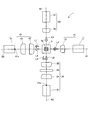
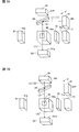
- FIG. 1 is a schematic configuration diagram of a water quality analyzer according to the first embodiment.
- the water quality analyzer 1 includes an excitation light irradiation optical system 10, a fluorescence detection optical system 20, a scattered light irradiation optical system 30, and a scattered light detection optical system 40 in four directions around the sample cell 5.
- the excitation light irradiation optical system 10 and the scattered light detection optical system 40 are arranged to face each other with the sample cell 5 interposed therebetween, and the scattered light irradiation optical system 30 and the fluorescence detection optical system 20 face each other with the sample cell 5 interposed therebetween. Are arranged.
- the optical axis A1 of the excitation light irradiation optical system 10 and the optical axis A2 of the fluorescence detection optical system 20 intersect perpendicularly, and the optical axis B1 of the scattered light irradiation optical system 30 and The optical axis B2 of the scattered light detection optical system 40 is arranged so as to intersect perpendicularly.
- the excitation light irradiation optical system 10 includes a light source 11 for excitation, and a collimator lens 12 disposed between the light source 11 and the sample cell 5.
- the fluorescence detection optical system 20 includes a fluorescence detector 21, a condenser lens 22, an optical filter 23, and a condenser lens 24 disposed between the fluorescence detector 21 and the sample cell 5.
- the condenser lenses 22 and 24 are arranged symmetrically with the convex surface facing the optical filter 23.
- the scattered light irradiation optical system 30 includes a light source 31 for detecting scattered light, and a collimating lens 32 disposed between the light source 31 and the sample cell 5.
- the scattered light detection optical system 40 includes a scattered light detector 41, and condensing lenses 42 and 43 disposed between the scattered light detector 41 and the sample cell 5.
- the condensing lenses 42 and 43 are arranged with their convex surfaces facing outward.
- the sample cell 5 is formed in a rectangular tube shape having a sample water channel 5a in the center, and extends in a direction perpendicular to the optical axes A1, A2, B1 and B2. Sample water to be measured is passed through the sample water channel 5a.
- a flow cell made of a transparent member such as quartz glass is used, but a square cell made of quartz glass can also be used.
- a light emitting diode, a laser diode, etc. which emit the light of a specific wavelength can be used.
- a photodiode, a photomultiplier tube, or the like can be used.
- the optical filter 23 is not particularly limited, and an optical element having a function of transmitting only light in a specific wavelength range and cutting other light and having a cut rate smaller than 100% is used.
- the light source 11 for excitation and the light source 31 for detecting scattered light are turned on.
- the actual sample is passed through the sample water channel 5 a of the sample cell 5.
- the excitation light source 11 emits excitation light source light L 1, and the light source light L 1 passes through the collimator lens 12 to become near-parallel light (collimated light) and is irradiated onto the sample water in the sample cell 5.
- the detection target component in the sample water is excited by the light source light L1 and emits fluorescence L2.
- the fluorescence L2 is collected by the condenser lens 22, reaches the optical filter 23, and after light of a specific wavelength is extracted by the optical filter 23, it is condensed by the condenser lens 24, and is received by the light receiving surface of the fluorescence detector 21. 21a is reached.
- a part of the light source light L1 travels straight through the sample cell 5, passes through the sample cell 5, and is collected by the condensing lenses 42 and 43 as transmitted light L 1 ′ and reaches the light receiving surface 41 a of the scattered light detector 41.
- a scattered light detection light source light L3 is emitted from the scattered light detection light source 31, and the light source light L3 passes through the collimator lens 32 to become near-parallel light and is irradiated onto the sample water in the sample cell 5.
- the light source light L3 is scattered by a fine particle component as a suspended substance in the sample water, and scattered light L4 is emitted.
- the scattered light L4 is collected by the condenser lenses 42 and 43 and reaches the light receiving surface 41a of the scattered light detector 41.
- a part of the light source light L3 travels straight through the sample cell 5, passes through the sample cell 5, is condensed by the condensing lens 22 as transmitted light L3 ′, and reaches the optical filter 23.
- most of the transmitted light L3 ′ is cut by the optical filter 23, a part of the transmitted light L3 ′ is transmitted and condensed on the condenser lens 24, and reaches the light receiving surface 21a of the fluorescence detector 21.
- the excitation light source 11 when monitoring the light amount of the excitation light source 11, the excitation light source 11 is turned on and the scattered light detection light source 31 is turned off.
- water pure water
- the light source light L1 emitted from the light source 11 passes through the collimator lens 12 and is irradiated to the sample cell 5.
- the light source light L1 passes through the sample cell 5 and is collected as transmitted light L1 ′ by the condenser lenses 42 and 43, reaches the light receiving surface 41a of the scattered light detector 41, and the transmitted light L1 ′ is detected.
- the excitation light source 11 When monitoring the light amount of the light source 31 for the scattered light detection 30, the excitation light source 11 is turned off and the scattered light detection light source 31 is turned on. Pure water is passed through the sample water channel 5 a of the sample cell 5.
- the light source light L3 emitted from the light source 31 passes through the collimating lens 32 and is irradiated to the sample cell 5.
- the light source light L3 passes through the sample cell 5, is condensed by the condenser lens 22 as transmitted light L3 ', and reaches the optical filter 23.
- a part of the transmitted light L3 ′ is condensed on the condenser lens 24 by the optical filter 23, reaches the light receiving surface 21a of the fluorescence detector 21, and the transmitted light L3 ′ is detected.
- the excitation light source 11 irradiates the sample cell 5 with the excitation light source light L1, and the fluorescence of a specific component in the sample water excited by the irradiation of the light source light L1.
- the fluorescence intensity is measured by detecting L2 with the fluorescence detector 21.
- the light source 31 for detecting scattered light is irradiated with the light source light L3 for detecting scattered light from the light source 31 for detecting scattered light, and the scattered light L4 scattered by the fine particles in the sample water by the irradiation of the light source light L3 is detected by the scattered light detector 41.
- Turbidity is measured by detecting. Since the fluorescence is detected while detecting the scattered light, the fluorescence intensity can be accurately measured while taking into account the influence of turbidity.
- the optical systems 10, 20, 30, 40 are the center of the sample water flow path 5 a of the sample cell 5, and the optical axis A 1 of the excitation light irradiation optical system 10 and the optical axis A 2 of the fluorescence detection optical system 20 are orthogonal to each other.
- the optical axis B1 of the irradiation optical system 30 and the optical axis B2 of the scattered light detection optical system 40 are arranged so as to be orthogonal to each other. For this reason, the fluorescence L2 emitted from the specific component in the sample water can be detected by the fluorescence detector 21 while suppressing the introduction of the transmitted light L1 ′ into the fluorescence detector 21. Further, the scattered light L4 emitted from the fine particles in the sample water can be detected by the scattered light detector 41 while suppressing the introduction of the transmitted light L3 ′ into the scattered light detector 41.
- the scattered light detector 41 transmits the transmitted light L1 ′ obtained by transmitting the light source light L1 through the sample cell 5. Can be detected. Since the light source 31 for detecting scattered light and the fluorescence detector 21 are arranged to face each other, the fluorescence detector 21 can detect the transmitted light L3 ′ transmitted through the sample cell 5 by the light source light L3.
- the excitation light source light L ⁇ b> 1 is irradiated from the excitation light source 11 to the sample cell 5, and the transmitted light L ⁇ b> 1 ′ transmitted through the sample cell 5 is detected by the scattered light detector 41.
- the light quantity of the light source 11 for excitation can be monitored.
- the sample cell 5 is irradiated with the light source light L3 for detecting scattered light from the light source 31 for detecting scattered light, and the transmitted light L3 ′ transmitted through the sample cell 5 is detected as a fluorescence detector.
- the transmitted light L3 ′ transmitted through the sample cell 5 is detected as a fluorescence detector.
- the fluorescence detector 21 of the fluorescence detection optical system 20 receives not only the fluorescence L2 emitted by the specific component in the sample water excited by the light source light L1 of the light source 11 but also the light source light L3.
- the transmitted light L3 ′ that has passed through the water is incident.
- the scattered light detector 41 of the scattered light detection optical system 40 not only the scattered light L4 scattered by the fine particles in the sample water due to the irradiation of the light source light L3 of the light source 31, but also the light source light L1 passes through the sample water.
- the transmitted light L1 ′ is incident.
- the optical axis B1 of the scattered light irradiation optical system 30 and the fluorescence detection optical system in the sample cell 5 The optical axis A2 of 20 may coincide with the optical axis A1 of the excitation light irradiation optical system 10 and the optical axis B2 of the scattered light optical system 40.
- the fluorescence 21 and the transmitted light L3 ′ are incident on the fluorescence detector 21, if the intensity of the transmitted light L3 ′ is significantly larger than the intensity of the fluorescence L2, the fluorescence is detected.
- the detection accuracy of the fluorescence L2 in the detector 21 is lowered.
- the scattered light L4 and the transmitted light L1 ′ are incident on the scattered light detector 41, if the intensity of the transmitted light L1 ′ is significantly larger than the intensity of the scattered light L4, the scattered light in the scattered light detector 41 is scattered. There is a possibility that the detection accuracy of the light L4 is lowered.
- the intersection of the optical axis A1 of the excitation light irradiation optical system 10 and the optical axis A2 of the fluorescence detection optical system 20 and the optical axis of the scattered light irradiation optical system 30 The amount of transmitted light L3 ′ and L1 ′ introduced into the detectors 21 and 41 is controlled by adjusting the distance between B1 and the optical axis B2 of the scattered light detection optical system 40.
- FIG. 2 is an explanatory diagram of a method for adjusting the amount of transmitted light introduced into each detector according to the above embodiment.
- the intersection P2 with the optical axis B2 is configured to be separated from the sample cell 5 by a distance D.
- the plane formed by the optical axis A1 of the excitation light irradiation optical system 10 and the optical axis A2 of the fluorescence detection optical system 20, and the optical axis B1 of the scattered light irradiation optical system 30 and the scattered light detection are detected.
- a plane formed by the optical axis B2 of the optical system 40 is separated by a distance D.
- the light L1 ′ is introduced at a position away from the optical axis B2 on the light receiving surface 41a of the scattered light detector 41.
- the intersection point P2 is positioned above the intersection point P1, but the intersection point P2 may be positioned below the intersection point P1.
- the distance D is preferably greater than 0 mm and not greater than 10 mm.
- the transmitted light L3 ′ and the optical axis A2 are prevented from matching, and the influence of the light amount of the transmitted light L3 ′ detected by the fluorescence detector 21 when measuring the sample water can be suppressed.
- the transmitted light L1 ′ is prevented from reaching the scattered light detector 41 or being too small to be difficult to detect even if it reaches the light, and the transmitted light L1 ′ is detected during light amount monitoring.
- the light quantity of the light source 11 can be monitored. Further, it is possible to prevent the transmitted light L3 ′ from reaching the fluorescence detector 21 or to be too small even if it reaches the fluorescence detector 21, and to detect the transmitted light L3 ′ and monitor the light amount of the light source 31 during light amount monitoring. Can do.
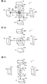
- FIG. 3 is an explanatory diagram of the measurement operation of the water quality analyzer according to the above embodiment.
- FIG. 3A is an explanatory diagram of the measurement operation of the fluorescence intensity and turbidity of the sample water according to the above embodiment.
- FIG. 3B is an explanatory diagram of the light amount detection operation of the excitation light irradiation optical system according to the above embodiment.
- FIG. 3C is an explanatory diagram of the light amount detection operation of the scattered light irradiation optical system according to the embodiment.
- Table 1 describes four measurement modes: normal measurement, light quantity monitoring reference, fluorescence light source light quantity detection, and scattered light source light quantity detection.
- the normal measurement mode shown in Table 1 is selected, and the fluorescence intensity and turbidity are measured.
- the actual sample is passed through the sample water channel 5 a of the sample cell 5.
- Both the excitation light source 11 and the scattered light detection light source 31 are turned on.
- the excitation light source 11 emits excitation light source light L1 and irradiates the sample water in the sample cell 5.
- the detection target component in the sample water is excited by the light source light L ⁇ b> 1 to emit fluorescence L ⁇ b> 2, and the fluorescence L ⁇ b> 2 reaches the light receiving surface 21 a of the fluorescence detector 21.
- Part of the light source light L1 travels straight through the sample cell 5, passes through the sample cell 5, and reaches the light receiving surface 41a of the scattered light detector 41 as transmitted light L1 ′.
- Scattered light detection light source 31 emits scattered light detection light source light L3 and irradiates the sample water in the sample cell 5.
- the light source light L3 is scattered by the fine particle component in the sample water, and the scattered light L4 reaches the light receiving surface 41a of the scattered light detector 41.
- a part of the light source light L3 travels straight through the sample cell 5, passes through the sample cell 5, and reaches the light receiving surface 21a of the fluorescence detector 21 as transmitted light L3 ′.
- the fluorescence L2 and transmitted light L3 ′ of the actual sample are detected on the light receiving surface 21a of the fluorescence detector 21, and the scattered light L4 of the actual sample is detected on the light receiving surface 41a of the scattered light detector 41.
- the transmitted light L1 ′ is detected.
- the light beam L3 transmitted through the sample cell 5 is separated by separating the optical axis B1 of the scattered light irradiation optical system 30 and the optical axis A2 of the fluorescence detection optical system 20 by a distance D.
- L3 ′ is introduced at a position away from the optical axis A2 on the light receiving surface 21a of the fluorescence detector 21.
- the transmitted light L1 ′ transmitted through the sample cell 5 by the light source light L1 is The light is introduced into the light receiving surface 41a of the scattered light detector 41 at a position away from the optical axis B2.
- the light quantity of the transmitted light L3 ′ introduced into the fluorescence detection optical system 20 can be adjusted, the influence of the transmitted light L3 ′ detected by the fluorescence detector 21 is suppressed, and the fluorescence L2 is accurately detected in the fluorescence detector 21. It can be detected well. Further, since the amount of transmitted light L1 ′ introduced into the scattered light detection optical system 40 can be adjusted, the influence of the amount of transmitted light L1 ′ detected by the scattered light detector 41 is suppressed, and the scattered light detector 41 Thus, the scattered light L4 can be detected with high accuracy.
- the reference mode for monitoring the light quantity is selected during the background measurement, and the background light quantity during the light quantity monitoring of the light sources 11 and 31 is detected.
- Water pure water that does not contain a fluorescent component and a scattered light component is passed through the sample cell 5.
- Both the excitation light source 11 and the scattered light detection light source 31 are OFF, and the background light quantity is detected by the fluorescence detector 21 and the scattered light detector 41. In general, since the detectors 21 and 41 are shielded from the outside, the amount of light in the background is almost zero.
- the light quantity detection mode of the excitation light source is selected, and the transmitted light L1 'of the light source 11 is detected.
- Pure water is passed through the sample water channel 5 a of the sample cell 5.
- the excitation light source 11 is turned on and the scattered light detection light source 31 is turned off.
- the light source light L1 emitted from the light source 11 is applied to the sample cell 5.
- the light source light L1 passes through the sample cell 5, reaches the light receiving surface 41a of the scattered light detector 41 as transmitted light L1 ′, and the transmitted light L1 ′ is detected. Since the scattered light detection optical system 40 (see FIG. 1) is disposed facing the excitation light irradiation optical system 10 (see FIG. 1), the transmitted light L1 ′ can be detected, and a dedicated light amount detector is provided.
- the light quantity of the light source 11 can be monitored without providing it.
- the light amount detection mode of the scattered light detection light source is selected, and the transmitted light L3 ′ of the light source 31 is detected.
- Pure water is passed through the sample water channel 5 a of the sample cell 5.
- the excitation light source 11 is turned off and the scattered light detection light source 31 is turned on.
- the light source light L3 emitted from the light source 31 is applied to the sample cell 5.
- the light source light L3 passes through the sample cell 5, reaches the light receiving surface 21a of the fluorescence detector 21 as transmitted light L3 ', and the transmitted light L3' is detected. Since the fluorescence detection optical system 20 (see FIG. 1) is disposed opposite to the scattered light irradiation optical system 30 (see FIG. 1), the transmitted light L3 ′ can be detected, and a dedicated light amount detector is provided. Therefore, the light amount of the light source 31 can be monitored.
- the water quality analyzer 1 includes the intersection P1 between the optical axis A1 of the excitation light irradiation optical system 10 and the optical axis A2 of the fluorescence detection optical system 20, and the scattered light irradiation optical system.
- the distance D is adjusted by separating the intersection P2 of the optical axis B1 of 30 and the optical axis B2 of the scattered light detection optical system 40 in the sample cell 5.
- the fluorescence detector 21 can accurately detect the fluorescence L2 while suppressing the influence of the transmitted light L3 ′, and the scattered light detector 41 suppresses the influence of the transmitted light L1 ′.
- the scattered light L4 can be detected with high accuracy.
- the scattered light detector 41 can detect the light amount of the transmitted light L1 ′, so that the scattered light detection optical system 40 does not provide a dedicated light amount detector.
- the amount of light of the light source 11 can be monitored.
- the light amount of the transmitted light L3 ′ can be detected by the fluorescence detector 21, so that the scattered light detection is performed in the fluorescence detection optical system 20 without providing a dedicated light amount detector.
- the amount of light of the light source 31 can be monitored. Accordingly, stable water quality analysis can be performed in consideration of a decrease in the light amount of the excitation light source 11 and the scattered light detection light source 31.
- the water quality analyzer irradiates a specific component in the sample water with excitation light for water in water and sewage systems, environmental water such as seawater, river water, lake water, etc., and sample water such as drainage.
- the emitted fluorescence is detected and a specific component is measured.
- the fluorescence intensity of specific components varies due to excitation light being affected by scattering, absorption, etc. by the suspended materials.
- the wavelength band is different between excitation light and scattered light detection light used for turbidity measurement. Since the light absorption characteristics in these two different wavelength bands differ depending on the sample water, the fluorescence of a specific component of the sample water may not be accurately measured only by correcting the fluorescence intensity by turbidity. That is, even if the suspended matter concentration in the sample water is the same, if the type of suspended matter is different, the absorption characteristics of the excitation light and fluorescence in the suspended matter will be different. Cannot be corrected.
- fluorescence emitted from specific components of the sample water also decreases due to absorption of the sample water.
- the wavelength of fluorescence is generally different from the wavelength of excitation light and irradiation light for turbidity measurement.
- the water quality analyzer has a fluorescence detection function and a turbidity detection function, and a transmitted light detecting optical system for transmitting transmitted light and turbidity through which excitation light has passed through the sample water.
- the transmitted light transmitted through the sample water is detected.
- Absorption characteristic at the wavelength of the excitation light is detected from the transmitted light transmitted through the sample water, and the absorption characteristic at the wavelength of the irradiated light for turbidity measurement is detected from the transmitted light transmitted through the sample water. This is used to predict the absorption characteristic at the wavelength of the fluorescence and correct the fluorescence intensity.
- the fluorescence emitted from the specific component in the sample water can be accurately measured without increasing the wavelength of light to be irradiated or detected.
- transmitted light in which the excitation light source light is transmitted through the sample cell and transmitted light in which the scattered light detection light source light is transmitted through the sample cell are detected by the transmitted light detection optical system.
- the absorbance at the wavelength of the light source light for exciting the sample water and the absorbance at the wavelength of the light source light for detecting scattered light are calculated from the transmitted light intensity, and the absorbance at the fluorescence wavelength is predicted from these absorbances. .
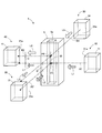
- FIG. 4 is a schematic configuration diagram of a water quality analyzer according to the second embodiment.
- FIG. 5 is a block diagram showing the configuration of the control unit according to the above embodiment.
- the water quality analyzer 2 includes a transmitted light detection optical system 100, a fluorescence detection optical system 70, a scattered light irradiation optical system 80 for detecting turbidity, and a scattered light detection optical system 90 in four directions around the sample cell 50. Yes.
- the fluorescence detection optical system 70 and the scattered light detection optical system 90 are arranged to face each other with the sample cell 50 interposed therebetween, and the scattered light irradiation optical system 80 and the transmitted light detection optical system 100 face each other with the sample cell 50 interposed therebetween. Are arranged.
- a half mirror (optical member) 55 is provided between the scattered light irradiation optical system 80 and the sample cell 50, and an excitation light irradiation optical system 60 is disposed on the side of the optical member 55. .
- the optical member 55 is disposed at a position for guiding the excitation light source light L1 and the scattered light detection light source light L3 described later to the sample cell 50.
- the optical member 55 and the transmitted light detection optical system 100 are opposed to each other with the sample cell 50 interposed therebetween.
- the excitation light irradiation optical system 60 has a light source 61 for excitation, and a collimator lens 62 disposed between the light source 61 and the optical member 55.
- the fluorescence detection optical system 70 includes a fluorescence detector 71, a condenser lens 72, an optical filter 73, and a condenser lens 74 disposed between the fluorescence detector 71 and the sample cell 50.
- the condenser lenses 72 and 74 are arranged symmetrically with the optical filter 73.
- the scattered light irradiation optical system 80 includes a light source 81 for detecting scattered light, and a collimator lens 82 disposed between the light source 81 and the optical member 55.
- the scattered light detection optical system 90 includes a scattered light detector 91 and condenser lenses 92 and 93 disposed between the scattered light detector 91 and the sample cell 50.
- the transmitted light detection optical system 100 includes a transmitted light detector 101 and a condensing lens 102 disposed between the sample cell 50.
- the light source 61 for excitation a light emitting diode, a laser diode, or the like that can emit light having a wavelength ⁇ 1 can be used.
- the light source 81 for detecting scattered light a light emitting diode, a laser diode, or the like that can emit light having a wavelength ⁇ 2 can be used.
- the wavelength ⁇ 1 of the excitation light source light L1 is preferably 250 nm or more and 350 nm or less
- the wavelength ⁇ 2 of the scattered light detection light source light L3 is preferably 600 nm or more and 900 nm or less.
- the scattered light detector 91 a silicon photodiode or the like that includes light having a wavelength ⁇ 2 of the light source light L3 for detecting scattered light in the detection range can be used.
- the fluorescence detector 71 a photomultiplier tube or the like can be used, whereby a minute fluorescence having a specific wavelength ⁇ 3 of the fluorescence selectively transmitted through the optical filter 73 can be detected.
- the optical filter 73 is not particularly limited, and a band pass filter or the like that selectively transmits only the fluorescence having the wavelength ⁇ 3 emitted by the target component to be detected can be used, thereby cutting light other than the wavelength ⁇ 3. Is done.
- the specific wavelength ⁇ 3 it is preferable to select the peak wavelength of fluorescence from the viewpoint of increasing the detection efficiency by the fluorescence detector 71.
- the wavelength ⁇ 3 is preferably not less than the wavelength ⁇ 1 and not more than the wavelength ⁇ 2.
- the light absorbency in wavelength (lambda) 3 can be accurately estimated in the estimation part mentioned later.
- the transmitted light detector 101 a silicon photodiode or the like that includes light of the wavelength ⁇ 1 of the excitation light source light L1 and light of the wavelength ⁇ 2 of the scattered light detection light source L3 in the detection range can be used.
- the optical member 55 a half mirror, a beam splitter, etc. can be used.
- the light source 61 for excitation and the light source 81 for detecting scattered light are alternately turned on.
- the actual sample is passed through the sample water channel 50a of the sample cell 50.
- the excitation light source 61 emits excitation light source light L1 having a wavelength ⁇ 1.
- the light source light L1 passes through the collimator lens 62 to become near-parallel light (collimated light), is reflected by the optical member 55, and is reflected by the sample cell 50.
- the sample water is irradiated.
- the detection target component in the sample water is excited by the light source light L1 and emits fluorescence L2.
- the fluorescence L2 is collected by the condenser lens 72, reaches the optical filter 73, and after the light L2 ′ having the specific wavelength ⁇ 3 is extracted by the optical filter 73, it is condensed by the condenser lens 74 and is detected by the fluorescence detector 71. Reaches the light receiving surface 71a. A part of the light source light L1 travels straight through the sample cell 50, passes through the sample cell 50, is collected by the condenser lens 102 as transmitted light L1 ′, and reaches the light receiving surface 101a of the transmitted light detector 101.
- the scattered light detection light source 81 emits scattered light detection light source light L3 having a wavelength ⁇ 2.
- the light source light L3 passes through the collimating lens 82 and becomes near-parallel light, passes through the optical member 55, and passes through the sample cell 50.
- the sample water is irradiated.
- the light source light L3 is scattered by a fine particle component as a suspended substance in the sample water, and scattered light L4 is emitted.
- the scattered light L4 is collected by the condenser lenses 92 and 93 and reaches the light receiving surface 91a of the scattered light detector 91. Further, a part of the light source light L3 travels straight through the sample cell 50, passes through the sample cell 50, is collected by the condenser lens 102 as transmitted light L3 ′, and reaches the light receiving surface 101a of the transmitted light detector 101.
- the excitation light source 61 irradiates the sample cell 50 with the excitation light source light L1 having the wavelength ⁇ 1, and the excitation in the sample water is excited by the irradiation of the light source light L1.
- the fluorescence intensity is measured by detecting the fluorescence L2 of wavelength ⁇ 3 emitted by the component with the fluorescence detector 71.
- the sample cell 50 is irradiated with the light source light L3 for detecting scattered light having the wavelength ⁇ 2 from the light source 81 for detecting scattered light, and the scattered light L4 scattered by the fine particles in the sample water is detected by the irradiation of the light source light L3.
- the turbidity is measured by detecting with the instrument 91. Since fluorescence is detected while detecting scattered light, the fluorescence intensity of a specific component to be detected in the sample water can be measured in consideration of the influence of turbidity.
- the traveling direction light of the excitation light source light L1 reflected by the optical member 55 and the optical axis C1 of the fluorescence detection optical system 70 are orthogonal to each other. For this reason, it is possible to detect the fluorescence L2 ′ emitted from a specific component in the sample water with the fluorescence detector 71 while suppressing the introduction of the transmitted light L1 ′ to the fluorescence detector 71.
- the optical axis D1 of the scattered light irradiation optical system 80 and the optical axis D2 of the scattered light detection optical system 90 are orthogonal to each other. Therefore, the scattered light L4 emitted from the fine particles in the sample water can be detected by the scattered light detector 91 while suppressing the transmission light L3 ′ from being introduced into the scattered light detector 91.
- the transmitted light detection optical system 100 faces the optical member 55 with the sample cell 50 interposed therebetween, and the excitation light source light L1 and the scattered light detection light source light L3 are supplied to the sample cell 50. It is arranged to lead to. Therefore, at the time of measuring the sample water, the excitation light source light L1 with the wavelength ⁇ 1 emitted from the excitation light source 61 is reflected by the optical member 55 and introduced into the sample cell 50, and the transmitted light L1 ′ transmitted through the sample cell 50 is transmitted. Can be detected by the transmitted light detector 101.
- the scattered light detection light source light L3 of wavelength ⁇ 2 emitted from the scattered light detection light source 81 passes through the optical member 55 and is introduced into the sample cell 50, and the transmitted light L3 ′ transmitted through the sample cell 50 is transmitted. It can be detected by the fluorescence detector 71.
- the prediction unit 121 (see FIG. 5) described later allows the sample cell 50 to pass the actual sample and pure water. The absorbance of the actual sample can be obtained by calculating the ratio of transmitted light intensity in each case.
- the water quality analyzer 2 is provided with a control unit 120 that performs overall control of each unit.
- the controller 120 repeatedly turns on and off the light source 61 for excitation and the light source 81 for scattered light detection by switching between a fluorescence detection mode and a turbidity detection mode, which will be described later.
- the control unit 120 includes a processor that executes various processes, a memory, and the like.
- the memory is composed of one or a plurality of storage media such as ROM (Read Only Memory) and RAM (Random Access Memory) depending on the application.
- the control unit 120 includes a prediction unit 121, a turbidity correction unit 122, and an absorbance correction unit 123. Note that the control unit 120 may include a control circuit, a controller, a control device, and the like.
- the absorbance of the sample water in the excitation light source light L1 having the wavelength ⁇ 1 is calculated from the transmitted light L1 ′ detected by the transmitted light detector 101, and the scattered light having the wavelength ⁇ 2 is detected from the transmitted light L3 ′.
- the absorbance of the sample water in the light source light L3 is calculated.
- the absorbance of the sample water in the fluorescence of the wavelength ⁇ 3 is predicted from the absorbance of the sample water at the wavelengths ⁇ 1 and ⁇ 2.
- the prediction unit 121 may include a prediction circuit, a predictor, a prediction device, and the like.
- the turbidity correction unit 122 corrects the fluorescence intensity of the sample water detected by the fluorescence detector 71 using the turbidity measured from the scattered light L4 having the wavelength ⁇ 2 detected by the scattered light detector 91. To correct the turbidity of the fluorescence intensity.
- the turbidity correction unit 122 may include a turbidity correction circuit, a turbidity corrector, a turbidity correction device, and the like.
- the absorbance correction unit 123 corrects the fluorescence intensity corrected by the turbidity correction unit 122 using the absorbance of the sample water at the wavelength ⁇ 1 calculated by the prediction unit 121 and the absorbance at the predicted wavelength ⁇ 3. Thus, the fluorescence intensity corrected for absorbance is calculated.
- the absorbance correction unit 123 may include an absorbance correction circuit, an absorbance corrector, an absorbance correction device, and the like.
- the water quality analyzer 2 predicts the absorbance at the wavelength ⁇ 3 from the absorbance of the sample water at the wavelengths ⁇ 1 and ⁇ 2. Accordingly, it is not necessary to install a light source or the like that emits light of wavelength ⁇ 3, measure the absorbance of sample water at wavelength ⁇ 3, and correct the fluorescence intensity using the measured value. It can be.
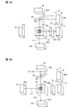
- FIG. 6 is an explanatory diagram of the measurement operation of the water quality analyzer in the normal measurement mode according to the above embodiment.
- FIG. 6A is an explanatory diagram of the measurement operation of the fluorescence intensity of the actual sample and the transmitted light of the excitation light source light according to the above embodiment.
- FIG. 6B is an explanatory diagram of the measurement operation of the scattered light intensity of the real sample and the transmitted light of the light source light for detecting the scattered light according to the embodiment.
- FIG. 7 is an explanatory diagram of the measurement operation of the water quality analyzer in the pure water measurement mode according to the above embodiment.
- FIG. 7A is an explanatory diagram of the measurement operation of the transmitted light of the light source light for the excitation light of pure water according to the above embodiment.
- FIG. 7B is an explanatory diagram of the measurement operation of the transmitted light of the light source light for detecting the scattered light of pure water according to the above embodiment.
- FIG. 8 is a diagram illustrating an example of the absorbance measurement of sample water containing a suspended substance. In FIG. 8, the horizontal axis represents wavelength and the vertical axis represents absorbance.
- the normal measurement mode shown in Table 2 is selected, and the actual sample is passed through the sample water flow path 50 a of the sample cell 50.
- FIG. 6A when measuring the fluorescence L2 ′ intensity of the specific component to be detected in the actual sample and the transmitted light L1 S ′ transmitted through the sample cell 50 by the excitation light source light L1, normal measurement is performed.
- the fluorescence detection mode in the mode is selected, and the intensity of the fluorescence L2 and the intensity of the transmitted light L1 S 'are measured.
- the excitation light source 61 is turned on, and the scattered light detection light source 81 is turned off.
- the excitation light source 61 emits excitation light source light L 1 having a wavelength ⁇ 1, is reflected by the optical member 55, and is applied to the actual sample of the sample cell 50.
- the detection target component in the actual sample is excited by the light source light L1 to emit fluorescence L2 having a peak on the longer wavelength side than the wavelength ⁇ 1 of the excitation light source light L1, and the fluorescence L2 is emitted by the optical filter 73 at a specific wavelength ⁇ 3.
- the light L2 ′ After the light L2 ′ is extracted, the light reaches the light receiving surface 71a of the fluorescence detector 71.
- a part of the light source light L1 travels straight through the sample cell 50, passes through the sample cell 50, and reaches the light receiving surface 101a of the transmitted light detector 101 as transmitted light L1 S ′.
- the turbidity in the normal measurement mode of Table 2 is measured.
- the degree detection mode is selected, and the intensity of the scattered light L4 and the intensity of the transmitted light L3 S ′ are measured.
- the excitation light source 61 is turned off, and the scattered light detection light source 81 is turned on.
- a scattered light detection light source light L3 having a wavelength ⁇ 2 is emitted from the scattered light detection light source 81, passes through the optical member 55, and is irradiated onto the actual sample of the sample cell 50.
- the light source light L3 is scattered by the fine particle component in the actual sample, and the scattered light L4 reaches the light receiving surface 91a of the scattered light detector 91. Part of the light source light L3 travels straight through the sample cell 50, passes through the sample cell 50, and reaches the light receiving surface 101a of the transmitted light detector 101 as transmitted light L3 S '.
- the fluorescence detector 71 detects the fluorescence component L2 ′ of the actual sample having the wavelength ⁇ 3, and the transmitted light detector 101 detects the transmitted light L1 S ′.
- the scattered light detector 91 detects the scattered light L4 of the actual sample, and the transmitted light detector 101 detects the transmitted light L3 S ′.
- the control unit 120 see FIG.
- the pure water measurement mode shown in Table 2 when measuring pure water, the pure water measurement mode shown in Table 2 is selected, and pure water is passed through the sample water flow path 50 a of the sample cell 50.
- the excitation light source light L1 measures the transmitted light L1 0 ′ transmitted through the pure water of the sample cell 50
- the fluorescence detection mode in the pure water measurement mode is selected, and the transmitted light detection is performed.
- the intensity of the transmitted light L1 0 ′ is detected by the device 101.
- the excitation light source 61 is turned on, and the scattered light detection light source 81 is turned off.
- the light source light L1 having the wavelength ⁇ 1 emitted from the excitation light source 61 is reflected by the optical member 55 and irradiated onto the pure water of the sample cell 50.
- Source light L1 is transmitted through the sample cell 5, 'reaches the light receiving surface 101a of the transmitted light detector 101, the transmitted light L1 0 as' is detected transmitted light L1 0.
- the turbidity detection mode in the pure water measurement mode is selected and transmitted.
- the intensity of the transmitted light L3 0 ′ is detected by the photodetector 101.
- the excitation light source 61 is turned off, and the scattered light detection light source 81 is turned on.
- the light source light L3 having the wavelength ⁇ 2 emitted from the light source 81 for detecting scattered light passes through the optical member 55 and is irradiated on the pure water of the sample cell 50.
- Source light L3 is transmitted through a sample cell 50 'reaches the light receiving surface 101a of the transmitted light detector 101, the transmitted light L3 0 as' is detected transmitted light L3 0.
- the absorbance indicating the absorbance of the sample water is calculated.
- the absorbance A ⁇ 1 of the actual sample in the excitation light source light L1 having the wavelength ⁇ 1 is calculated.
- the absorbance A ⁇ 2 of the actual sample in the light L3 is calculated.
- the pure water measurement mode is selected by the control unit 120 (see FIG. 5), and the transmitted light L1 0 ′ of the excitation light source light L1 and the transmitted light source light L3 for detecting scattered light in pure water are transmitted.
- the light L3 0 ′ is measured in advance or periodically.
- the types of suspended substances and the absorption characteristics of sample water will be described. Even if the concentration of the suspended substance in the sample water, that is, the turbidity is the same, the absorption characteristics of excitation light and fluorescence in the suspended substance differ depending on the type of suspended substance.
- the solid line indicates the absorption spectrum of the white suspension solution
- the broken line indicates the absorption spectrum of the black suspension solution.
- the turbidity measured by the scattered light measurement is the same, but the absorption spectra differ greatly because the types of the suspended substances are different.
- the absorbance of the sample water containing the white suspended substance tended to increase on the short wavelength side and decrease on the long wavelength side.
- the absorbance of the sample water containing the black suspended substance has a wide range of wavelengths that have the same magnitude from a short wavelength to a long wavelength. Note that, in light of a predetermined wavelength, the greater the absorbance, the greater the absorption of light by the sample water. Therefore, even if the sample water has the same concentration of the detection target component, the fluorescence intensity detected by the fluorescence detector 71 is Get smaller.
- the absolute value of the absorbance on the short wavelength side and the absorbance on the long wavelength side and the ratio thereof vary greatly depending on the type of suspended matter contained in the sample water. For this reason, from the absolute value of the absorbance on the short wavelength side and the absorbance on the long wavelength side and the ratio thereof, the absorbance at the specific wavelength, that is, the fluorescence wavelength can be predicted. A linear approximation method or the like can be used to predict the absorbance at a specific wavelength.
- the wavelength ⁇ 1 of the excitation light source light L1 is set to, for example, 250 nm or more and 350 nm or less on the short wavelength side in the ultraviolet region
- the fluorescence of organic substances and oil components that are detection target components in the actual sample is, for example, 350 nm to 500 nm as the peak wavelength. Appears near. That is, it is fluorescence of wavelength ⁇ 3 emitted by a specific component in the sample water.
- the wavelength ⁇ 2 of the scattered light detection light source light L3 used for turbidity measurement near infrared light is used from visible light having a wavelength of 600 nm to 900 nm on the long wavelength side, for example.
- the absorbance A ⁇ 1 of the actual sample in the excitation light source light L1 having the wavelength ⁇ 1 from the actually measured transmitted light L1 S ′ and L1 0 ′ and the wavelength from the actually measured transmitted light L3 S ′ and L3 0 ′.
- the absorbance A ⁇ 2 of the actual sample in the light source light L3 for detecting scattered light of ⁇ 2 is calculated.
- the prediction unit 121 an absorbance A .lambda.1 of short wavelength .lambda.1 side absolute value of the absorbance A .lambda.2 the long wavelength .lambda.2 side and its ratio to predict the absorbance A [lambda] 3 of the fluorescence at the wavelength [lambda] 3 between the wavelength .lambda.1 and the wavelength .lambda.2.
- the wavelength ⁇ 3 is preferably the peak wavelength of the fluorescence spectrum.
- the actually measured transmitted light L1 S ', L1 0' and L3 S ', L3 0' wavelengths .lambda.1 calculated from the absorbance A .lambda.1 real sample in .lambda.2, predicting absorbance A [lambda] 3 from A .lambda.2 at the wavelength [lambda] 3
- the fluorescence intensity of the detection target component can be accurately measured regardless of the type of suspended substance.
- the water quality analyzer 2 can have a simple configuration.
- the water quality analyzer 2 includes the transmitted light L1 ′ of the excitation light source light L1 having the first wavelength ⁇ 1 and the light source light L3 for detecting scattered light having the second wavelength ⁇ 2.
- the absorbances A ⁇ 1 and A ⁇ 2 of the sample water at the first wavelength ⁇ 1 and the second wavelength ⁇ 2 are calculated from the transmitted light L3 ′.
- absorbance A .lambda.1 predicts the absorbance A [lambda] 3 in fluorescence of the third wavelength [lambda] 3 by using the A .lambda.2, using the absorbance A [lambda] 3 in fluorescence of the third wavelength [lambda] 3 to the correction of the fluorescence intensity of the measurement target component.
- the fluorescence intensity can be accurately measured, and a light source that emits light of the third wavelength ⁇ 3 and a detector that detects the transmitted light of the light source light are provided in the water quality analyzer 2 to correct the fluorescence intensity. Since it is not necessary to measure the absorbance of the sample water at the third wavelength ⁇ 3, the water quality analyzer 2 can have a simple configuration.
- the present invention is not limited to the first and second embodiments, and can be implemented with various modifications.
- the size, shape, and the like illustrated in the accompanying drawings are not limited to this, and can be appropriately changed within a range in which the effect of the present invention is exhibited.
- various modifications can be made without departing from the scope of the object of the present invention.
- the arrangement of the optical systems 10, 20, 30, and 40 is such that the fluorescence detection optical system 20 can detect the light amount of the scattered light irradiation optical system 30 and the scattered light detection optics. If the system 40 is arrange
- the optical systems 10, 20, 30, and 40 are configured such that the fluorescence L2 and the transmitted light L3 ′ are introduced into the light receiving surface 21a of the fluorescence detector 21, and the scattered light L4 and the transmitted light are transmitted. If light L1 'is introduce
- the excitation light irradiation optical system 10 and the scattered light irradiation optical system 30 are configured to include the collimating lenses 12 and 32.
- the light sources 11 and 31 are preliminarily incorporated with lenses. If a light source capable of forming near-parallel light is used, the collimating lenses 12 and 32 may not be included.
- the sample cell 5 is formed in a rectangular tube shape.
- the fluorescence detector 21 detects the fluorescence L2 and the transmitted light L3 ′
- the scattered light detector 41 detects the fluorescence.
- the configuration is not limited to this configuration as long as the scattered light L4 and the transmitted light L1 ′ are detected.
- the arrangement of the optical systems 60, 70, 80, 90, 100 is such that the transmitted light detection optical system 100 can detect the light amount of the scattered light irradiation optical system 80 and is excited. If it arrange
- each optical system 60, 70, 80, 90, 100 is such that fluorescence L2 ′ is introduced into the light receiving surface 71a of the fluorescence detector 71, and scattered light L4 is detected by scattered light.
- fluorescence L2 ′ is introduced into the light receiving surface 71a of the fluorescence detector 71
- scattered light L4 is detected by scattered light.
- the excitation light irradiation optical system 60 and the scattered light irradiation optical system 80 are configured to include the collimating lenses 62 and 82, but lenses are incorporated in the light sources 61 and 81 in advance. If a light source capable of forming near-parallel light is used, the collimating lenses 62 and 82 may not be included.
- the sample cell 50 is formed in a rectangular tube shape.
- the fluorescence L2 ′ is detected by the fluorescence detector 71
- the scattered light L4 is detected by the scattered light detector 41.
- the configuration is not limited to this configuration as long as the transmitted light detector 101 detects the transmitted lights L1 ′ and L3 ′.
- the configuration in which the absorbance A ⁇ 3 at the wavelength ⁇ 3 is predicted from the measured absorbances A ⁇ 1 and A ⁇ 2 at the actually measured wavelengths ⁇ 1 and ⁇ 2 in the second embodiment, and the fluorescence intensity is corrected for the absorbance using this is described in the first embodiment. You may apply to.
- Absorbance A ⁇ 2 at ⁇ 2 is calculated.
- the absorbance A ⁇ 1 at the wavelength ⁇ 1 is calculated from the transmitted light L1 ′ of the excitation light source 11 having the wavelength ⁇ 1 detected by the scattered light detector 41.
- the absorbance A ⁇ 3 at the wavelength ⁇ 3 can be predicted.
- the water quality analyzer of the present invention includes an excitation light irradiation optical system for irradiating a sample water to be measured with excitation light source light, and fluorescence of a specific component in the sample water excited by irradiation of the excitation light source light.
- Fluorescence detection optical system for detecting, scattered light irradiation optical system for irradiating the sample water with light source light for detecting scattered light, and scattered light scattered by fine particles in the sample water by irradiation of the light source light for detecting scattered light
- a scattered light detecting optical system for detecting the light quantity of the excitation light irradiation optical system and the light quantity of the scattered light irradiation optical system.
- the fluorescence detection optical system can detect the light amount of the scattered light irradiation optical system, and the scattered light detection optical system can detect the light amount of the excitation light irradiation optical system. It is arranged to be.
- the fluorescence detection optical system when measuring the sample water, the fluorescence is detected by the fluorescence detection optical system while detecting the scattered light by the scattered light detection optical system. Strength can be measured with high accuracy.
- the scattered light detection optical system when monitoring the light amount of the excitation light source, the scattered light detection optical system can also detect the light amount of the excitation light source. Therefore, without providing a dedicated light amount detector, the scattered light detection optical system can be used for excitation. The light quantity of the light source can be monitored.
- the fluorescence detection optical system when monitoring the amount of light from the light source for scattered light detection, the fluorescence detection optical system can also detect the amount of light from the light source for scattered light detection, so it is possible to detect scattered light in the fluorescence detection optical system without providing a dedicated light amount detector. It is possible to monitor the amount of light of the light source for use. Accordingly, stable water quality analysis can be performed in consideration of a decrease in the light amount of the excitation light source and the scattered light detection light source.
- the excitation light irradiation optical system and the scattered light detection optical system are opposed to each other with a sample water passage container interposed therebetween, and the scattered light irradiation optical system and the fluorescence detection optical system are The sample water passage container is opposed to the other.
- the excitation light irradiation optical system and the scattered light detection optical system are opposed to each other, it is possible to detect the amount of transmitted light that has passed through the sample water flow container for the excitation light source light.
- the scattered light irradiation optical system and the fluorescence detection optical system are opposed to each other, it is possible to detect the amount of transmitted light that has passed through the sample water passage container of the light source light for detecting scattered light. Thereby, the light quantity monitoring of each light source can be performed.
- the optical axis of the excitation light irradiation optical system and the optical axis of the fluorescence detection optical system intersect perpendicularly at the center in the sample water flow container, and the scattered light irradiation optical system
- the optical axis of the system and the optical axis of the scattered light detection optical system intersect perpendicularly.
- the first intersection of the optical axis of the excitation light irradiation optical system and the optical axis of the fluorescence detection optical system, the optical axis of the scattered light irradiation optical system, and the scattered light detection optics The second intersection point with the optical axis of the system is separated in the sample water flow container.
- the accuracy of the detection function of the light source light for excitation can be maintained while suppressing the influence of the transmitted light that has passed through the water container. Since the optical axis of the excitation light irradiation optical system and the optical axis of the scattered light detection optical system are separated from each other, the scattered light detection optical system transmits the excitation light source light through the sample water flow container when measuring the sample. The accuracy of the light source light detection function for detecting scattered light can be maintained while suppressing the influence of transmitted light.
- the distance between the first intersection and the second intersection is greater than 0 mm and not more than 10 mm.
- the absorbance of the sample water at the first wavelength of the light source light for excitation is calculated from the first transmitted light through which the light source light for excitation has passed through the sample water, and the scattered light
- the absorbance of the sample water at the second wavelength of the scattered light detection light source light is calculated from the second transmitted light through which the detection light source light has passed through the sample water, and the first wavelength and the second wavelength are calculated.
- the absorbance at the third wavelength fluorescence is predicted using these absorbances, and the absorbance at the third wavelength fluorescence is used to correct the fluorescence intensity of the measurement target component.
- the fluorescence intensity can be measured with high accuracy, and a light source that emits light of the third wavelength for correcting the fluorescence intensity and a detector that detects the transmitted light of the light source light are provided in the water quality analyzer. Since it is not necessary to measure the absorbance of the sample water at the third wavelength, the water quality analyzer can have a simple configuration.
- the absorbance of the sample water at the third wavelength is predicted from the absolute value and the ratio of the absorbance of the sample water at the first wavelength and the second wavelength. With this configuration, the absorbance at the third wavelength can be accurately predicted according to the type of suspended matter contained in the sample water.
- the excitation light source light transmits the first transmitted light transmitted through the sample water and the scattered light detection light source light transmits the second transmitted light transmitted through the sample water.
- the light detection optical system calculates the absorbance of the sample water at the first wavelength of the excitation light source light from the first transmitted light, and calculates the scattered light detection light source light from the second transmitted light.
- a prediction unit that calculates the absorbance of the sample water at the second wavelength and predicts the absorbance of the sample water at the third wavelength of the fluorescence from the absorbance of the sample water at the first wavelength and the second wavelength.
- the absorbance of the sample water at the first wavelength and the second wavelength is calculated from the transmitted light of the first wavelength excitation light source light and the transmitted light of the second wavelength scattered light detection light source light.
- the absorbance at the third wavelength fluorescence is predicted using these absorbances, and the absorbance at the third wavelength fluorescence is used to correct the fluorescence intensity of the measurement target component.
- the fluorescence intensity can be measured with high accuracy, and a light source or the like that irradiates the light of the third wavelength is provided in the water quality analyzer to correct the fluorescence intensity, and the absorbance at the third wavelength of the sample water is measured. Since it is not necessary, the water quality analyzer can have a simple configuration.
- the absorbance of the sample water at the third wavelength is predicted from the absolute value and the ratio of the absorbance of the sample water at the first wavelength and the second wavelength. With this configuration, the absorbance at the third wavelength can be accurately predicted according to the type of fine particles in the sample water.
- the third wavelength is the peak wavelength of the fluorescence spectrum of the specific component in the sample water.
- the turbidity correction unit calculates the fluorescence intensity corrected for turbidity.
- the turbidity corrected fluorescence intensity using the absorbance of the sample water at the first wavelength and the absorbance of the sample water at the third wavelength predicted by the prediction unit is provided.
- the first wavelength is not less than 250 nm and not more than 350 nm
- the second wavelength is not less than 600 nm and not more than 900 nm
- the third wavelength is not less than the first wavelength. It is preferable that the second wavelength or less. With this configuration, it is possible to accurately predict the absorbance at the third wavelength between the absorbance at the first wavelength on the short wavelength side and the absorbance at the second wavelength on the long wavelength side.
- the water quality analyzer of the present invention includes an optical member disposed at a position for guiding the excitation light source light and the scattered light detection light source light to the sample water flow container, and the optical member and the transmitted light.
- a detection optical system is opposed to the sample water passage container.
Landscapes
- Health & Medical Sciences (AREA)
- Life Sciences & Earth Sciences (AREA)
- Chemical & Material Sciences (AREA)
- Physics & Mathematics (AREA)
- Pathology (AREA)
- Immunology (AREA)
- General Physics & Mathematics (AREA)
- Analytical Chemistry (AREA)
- Biochemistry (AREA)
- General Health & Medical Sciences (AREA)
- Food Science & Technology (AREA)
- Medicinal Chemistry (AREA)
- Engineering & Computer Science (AREA)
- Nuclear Medicine, Radiotherapy & Molecular Imaging (AREA)
- Investigating, Analyzing Materials By Fluorescence Or Luminescence (AREA)
- Spectroscopy & Molecular Physics (AREA)
- Investigating Or Analysing Materials By Optical Means (AREA)
- Sampling And Sample Adjustment (AREA)
- Analysing Materials By The Use Of Radiation (AREA)
Abstract
簡易な構成で蛍光検出機能と散乱光検出機能を併せ持ち、試料水の蛍光強度を精度良く測定すること。水質分析計(1)は、測定対象となる試料水に励起用の光源光(L1)を照射する励起光照射光学系(10)と、励起用の光源光の照射により励起された試料水中の特定成分の蛍光(L2)を検出する蛍光検出光学系(21)と、試料水に散乱光検出用の光源光(L3)を照射する散乱光照射光学系(30)と、散乱光検出用の光源光の照射により試料水中の微粒子で散乱された散乱光(L4)を検出する散乱光検出光学系(40)と、を有している。励起光照射光学系の光量及び散乱光照射光学系の光量を検出可能である。
Description
本発明は、測定対象になる試料水の成分を測定する水質分析計に関する。
一般的に蛍光検出の原理を用いる水質分析計においては、測定対象の試料水中の特定成分の励起によって発せられた蛍光を検出して、試料水を水質分析するものが知られている。この水質分析計は、光源から発せられた励起光を試料セル中の試料水に照射して、特定成分を励起させ、励起により放出された蛍光を光学フィルタに通して特定波長の光を取り出し、特定波長の光を蛍光検出器に導入して蛍光検出している。このような水質分析計においては、光源から発せられた光が直接検出器に導入されることを防ぐために、光源から試料セルへの照射系の光路と、試料セルから検出器への検出系の光路とは、垂直に交わるように配置されている(例えば、特許文献1参照)。
ところで、試料水中の成分における蛍光強度は、試料水が混濁している(濁度が高い)と減衰することが知られており、試料水の蛍光強度を精度良く測定するためには濁度を測定する必要がある。散乱光検出の原理を利用する濁度計においては、光源から発せられた特定波長の光を測定対象の試料水が収容されている試料セルに照射して、試料水に含まれる懸濁物質としての微粒子による散乱光を散乱光検出器により検出して、濁度が測定される。
近年、試料水の蛍光強度と濁度を同時に測定するために、蛍光検出機能と散乱光検出機能を併せ持つ水質分析計に対するニーズが高まってきている。蛍光検出機能と散乱光検出機能とを複合した水質分析計においては、励起用の光源及び検出器、散乱光検出用の光源及び検出器が備えられている必要がある。また、水質分析計の安定的な測定には、各々の光源の光量の低下をモニタリングすることが望ましい。
しかしながら、このような水質分析計は、付加的な機能を追加すると構成が複雑になってしまう。例えば、蛍光検出機能と散乱光検出機能とを複合した水質分析計において、各光源の光量を測定するためにはそれぞれの光源に対して光量検出器が備えられている必要があり、構成が複雑化してしまう問題がある。
本発明は、このような問題に鑑みてなされたもので、その目的とするところは、簡易な構成で蛍光検出機能と付加的な機能として散乱光検出機能を併せ持ち、試料水の蛍光強度を精度良く測定することができる水質分析計を提供することにある。
本発明の水質分析計は、測定対象となる試料水に励起用の光源光を照射する励起光照射光学系と、前記励起用の光源光の照射により励起された試料水中の特定成分の蛍光を検出する蛍光検出光学系と、試料水に散乱光検出用の光源光を照射する散乱光照射光学系と、前記散乱光検出用の光源光の照射により試料水中の微粒子で散乱された散乱光を検出する散乱光検出光学系と、を有し、励起光照射光学系の光量及び散乱光照射光学系の光量を検出可能であることを特徴とする。
本発明の水質分析計は、測定対象となる試料水に励起用の光源光を照射する励起光照射光学系と、前記励起用の光源光の照射により励起された試料水中の特定成分の蛍光を検出する蛍光検出光学系と、試料水に散乱光検出用の光源光を照射する散乱光照射光学系と、前記散乱光検出用の光源光の照射により試料水中の微粒子で散乱された散乱光を検出する散乱光検出光学系と、を有し、前記蛍光検出光学系が、前記散乱光照射光学系の光量を検出可能で且つ、前記散乱光検出光学系が、前記励起光照射光学系の光量を検出可能であるように配置されていることを特徴とする。
この構成により、試料水測定時には、散乱光検出光学系で散乱光を検出しながら蛍光検出光学系で蛍光を検出しているため、試料水の濁度の影響を考慮しながら、試料水の蛍光強度を精度良く測定することができる。また、励起用の光源の光量モニタリング時には、散乱光検出光学系が励起用の光源の光量も検出することができるため、専用の光量検出器を設けることなく、散乱光検出光学系において励起用の光源の光量モニタリングをすることができる。散乱光検出用の光源の光量モニタリング時には、蛍光検出光学系が散乱光検出用の光源の光量も検出することができるため、専用の光量検出器を設けることなく、蛍光検出光学系において散乱光検出用の光源の光量モニタリングをすることができる。これにより、励起用の光源及び散乱光検出用の光源の光量の低下を考慮して安定した水質分析を行うことができる。
本発明によれば、簡易な構成で蛍光検出機能と付加的な機能として散乱光検出機能を併せ持ち、試料水の蛍光強度を精度良く測定することができる。
以下、本発明の第1の実施の形態に係る水質分析計について、詳細に説明する。図1は、第1の実施の形態の水質分析計の概略構成図である。
水質分析計1は、試料セル5を中心にして4方向に励起光照射光学系10、蛍光検出光学系20、散乱光照射光学系30、及び散乱光検出光学系40を備えている。励起光照射光学系10と散乱光検出光学系40とは、試料セル5を挟んで対向して配置され、散乱光照射光学系30と蛍光検出光学系20とは、試料セル5を挟んで対向して配置されている。試料セル5の試料水流路5aの中心で、励起光照射光学系10の光軸A1と蛍光検出光学系20の光軸A2とが垂直に交差し、散乱光照射光学系30の光軸B1と散乱光検出光学系40の光軸B2とが垂直に交差するように配置されている。
励起光照射光学系10は、励起用の光源11と、光源11と試料セル5との間に配置されたコリメートレンズ12とを有している。蛍光検出光学系20は、蛍光検出器21と、蛍光検出器21と試料セル5との間に配置された集光レンズ22、光学フィルタ23、集光レンズ24とを有している。集光レンズ22、24は、光学フィルタ23に凸面を向けて対称に配置されている。また、散乱光照射光学系30は、散乱光検出用の光源31と、光源31と試料セル5との間に配置されたコリメートレンズ32とを有している。散乱光検出光学系40は、散乱光検出器41と、散乱光検出器41と試料セル5との間に配置された集光レンズ42、43とを有している。集光レンズ42、43は、凸面を互いに外側に向けて配置されている。
試料セル5は、中心に試料水流路5aを有する角筒状に形成されており、光軸A1、A2、B1及びB2に対して垂直方向に延びている。試料水流路5aには測定対象となる試料水が通水される。試料セル5としては、石英ガラス等の透明部材から成るフローセルが用いられるが、石英ガラスから成る角型セルを用いることもできる。また、光源11、光源31としては、特定波長の光を発する発光ダイオード、レーザーダイオード等を用いることができる。また、蛍光検出器21、散乱光検出器41としては、フォトダイオード、光電子増倍管等を用いることができる。光学フィルタ23としては、特に限定されないが、特定の波長範囲の光だけを透過させ、それ以外の光をカットする機能を有し、カット率が100%より小さい光学素子が用いられる。
このような構成において、試料水測定時には、励起用の光源11及び散乱光検出用の光源31を点灯させる。試料セル5の試料水流路5a内には、実試料が通水される。励起用の光源11からは、励起用の光源光L1が発せられ、光源光L1はコリメートレンズ12を通って近平行光(コリメート光)となり、試料セル5の試料水に照射される。試料水中の検出対象成分は、光源光L1によって励起されて蛍光L2を発する。蛍光L2は、集光レンズ22により集光され、光学フィルタ23に到達し、光学フィルタ23により特定波長の光が取り出された後に、集光レンズ24によって集光され、蛍光検出器21の受光面21aに達する。また、光源光L1の一部は試料セル5を直進し、試料セル5を透過して透過光L1´として集光レンズ42、43によって集光され散乱光検出器41の受光面41aに達する。
散乱光検出用の光源31からは、散乱光検出用の光源光L3が発せられ、光源光L3はコリメートレンズ32を通って近平行光となり、試料セル5の試料水に照射される。光源光L3は試料水中の懸濁物質としての微粒子成分により散乱され、散乱光L4が発せられる。散乱光L4は、集光レンズ42、43によって集光され、散乱光検出器41の受光面41aに達する。また、光源光L3の一部は試料セル5を直進し、試料セル5を透過して透過光L3´として集光レンズ22により集光され、光学フィルタ23に到達する。光学フィルタ23によって透過光L3´はその大部分がカットされるが、一部は透過して集光レンズ24に集光され、蛍光検出器21の受光面21aに達する。
続いて、励起用の光源11の光量モニタリング時には、励起用の光源11を点灯させて、散乱光検出用の光源31を消灯させる。試料セル5の試料水流路5a内には、蛍光成分及び散乱光成分を含まない水(純水)が通水される。光源11から発せられた光源光L1はコリメートレンズ12を通り、試料セル5に照射される。光源光L1は試料セル5を透過して、透過光L1´として集光レンズ42、43によって集光され、散乱光検出器41の受光面41aに達し、透過光L1´が検出される。
散乱光検出用30の光源31の光量モニタリング時には、励起用の光源11を消灯させて、散乱光検出用の光源31を点灯させる。試料セル5の試料水流路5a内には、純水が通水される。光源31から発せられた光源光L3はコリメートレンズ32を通り、試料セル5に照射される。光源光L3は試料セル5を透過して、透過光L3´として集光レンズ22により集光され、光学フィルタ23に到達する。光学フィルタ23によって透過光L3´の一部が集光レンズ24に集光され、蛍光検出器21の受光面21aに達し、透過光L3´が検出される。
このように水質分析計1では、試料水測定時に、励起用の光源11から試料セル5に励起用の光源光L1が照射され、光源光L1の照射により励起された試料水中の特定成分の蛍光L2を蛍光検出器21で検出することで蛍光強度が測定される。同時に、散乱光検出用の光源31から試料セル5に散乱光検出用の光源光L3が照射され、光源光L3の照射により試料水中の微粒子で散乱された散乱光L4を散乱光検出器41で検出することで濁度が測定される。散乱光を検出しながら蛍光を検出しているため、濁度の影響を考慮しながら蛍光強度を精度良く測定することができる。
光学系10、20、30、40は、試料セル5の試料水流路5aの中心で、励起光照射光学系10の光軸A1と蛍光検出光学系20の光軸A2とが直交し、散乱光照射光学系30の光軸B1と散乱光検出光学系40の光軸B2とが直交するように配置されている。このため、透過光L1´の蛍光検出器21への導入を抑えながら、蛍光検出器21で試料水中の特定成分から発せられた蛍光L2を検出することができる。また、透過光L3´の散乱光検出器41への導入を抑えながら、散乱光検出器41で試料水中の微粒子から発せられた散乱光L4を検出することができる。
また、水質分析計1では、励起用の光源11と散乱光検出器41は対向して配置されているので、散乱光検出器41は、光源光L1が試料セル5を透過した透過光L1´を検出可能となっている。散乱光検出用の光源31と蛍光検出器21は対向して配置されているので、蛍光検出器21は、光源光L3が試料セル5を透過した透過光L3´を検出可能となっている。
このため、励起用の光源11の光量モニタリング時には、励起用の光源11から試料セル5に励起用の光源光L1が照射され、試料セル5を透過した透過光L1´を散乱光検出器41で検出することで、励起用の光源11の光量をモニタリングすることができる。散乱光検出用の光源31の光量モニタリング時には、散乱光検出用の光源31から試料セル5に散乱光検出用の光源光L3が照射され、試料セル5を透過した透過光L3´を蛍光検出器21で検出することで、散乱光検出用の光源31の光量をモニタリングすることができる。
ところで、試料水測定時には、蛍光検出光学系20の蛍光検出器21には、光源11の光源光L1で励起された試料水中の特定成分により発せられた蛍光L2だけでなく、光源光L3が試料水を透過した透過光L3´が入射される。同様に、散乱光検出光学系40の散乱光検出器41には、光源31の光源光L3の照射により試料水中の微粒子で散乱された散乱光L4だけでなく、光源光L1が試料水を透過した透過光L1´が入射される。
光源11、31の光量モニタリング時に透過光L1´、L3´の検出器41、21における検出効率を高めるには、試料セル5内において、散乱光照射光学系30の光軸B1と蛍光検出光学系20の光軸A2とを一致させ、励起光照射光学系10の光軸A1と散乱光光学系40の光軸B2とを一致させればよい。しかしながら上記したように、試料水の測定時には、蛍光検出器21に蛍光21及び透過光L3´が入射されるため、透過光L3´の強度が蛍光L2の強度に比べて著しく大きい場合は、蛍光検出器21における蛍光L2の検出精度が下がってしまう恐れがある。同様に、散乱光検出器41に散乱光L4及び透過光L1´が入射されるため、透過光L1´の強度が散乱光L4の強度に比べて著しく大きい場合は、散乱光検出器41における散乱光L4の検出精度が下がってしまう恐れがある。
そこで第1の実施の形態に係る水質分析計1においては、励起光照射光学系10の光軸A1と蛍光検出光学系20の光軸A2との交点と、散乱光照射光学系30の光軸B1と散乱光検出光学系40の光軸B2との距離を調整して、検出器21、41に導入される透過光L3´、L1´の光量を制御するようにしている。
図2は、上記実施の形態に係る各検出器に導入される透過光の光量の調整方法の説明図である。図2に示すように、励起光照射光学系10の光軸A1と蛍光検出光学系20の光軸A2との交点P1と、散乱光照射光学系30の光軸B1と散乱光検出光学系40の光軸B2との交点P2とが、試料セル5内で距離Dだけ離間して構成される。すなわち、試料セル5内において、励起光照射光学系10の光軸A1と蛍光検出光学系20の光軸A2とで形成される平面と、散乱光照射光学系30の光軸B1と散乱光検出光学系40の光軸B2とで形成される平面とが、距離Dだけ離間して構成される。これにより、光源光L3が試料セル5を透過した透過光L3´は、蛍光検出器21の受光面21aにおいて光軸A2から離れた位置に導入され、光源光L1が試料セル5を透過した透過光L1´は、散乱光検出器41の受光面41aにおいて光軸B2から離れた位置に導入される。図2では、交点P2が交点P1の上方に位置する構成としたが、交点P2は交点P1の下方に位置する構成としてもよい。
なお、距離Dは、0mmより大きく10mm以下であることが好ましい。距離Dが0mmより大きいと、透過光L3´と光軸A2が一致することを防いで、試料水の測定時に蛍光検出器21で検出される透過光L3´の光量の影響を抑えることができる。また、透過光L1´と光軸Bが一致することを防いで、試料水の測定時に散乱光検出器41で検出される透過光L1´の光量の影響を抑えることができる。距離Dが10mm以下であると、透過光L1´が散乱光検出器41に到達されないこと又は到達しても微少すぎて検出困難となることを防ぎ、光量モニタリング時に透過光L1´を検出して光源11の光量モニタリングをすることができる。また、透過光L3´が蛍光検出器21に到達されないこと又は到達しても微小すぎて検出困難となることを防ぎ、光量モニタリング時に透過光L3´を検出して光源31の光量モニタリングをすることができる。
次に、図3及び表1を参照して、上記実施の形態に係る水質分析計1による試料水の測定動作について説明する。図3は、上記実施の形態に係る水質分析計の測定動作の説明図である。図3Aは、上記実施の形態に係る試料水の蛍光強度及び濁度の測定動作の説明図である。図3Bは、上記実施の形態に係る励起光照射光学系の光量の検出動作の説明図である。図3Cは、上記実施の形態に係る散乱光照射光学系の光量の検出動作の説明図である。また、表1には通常測定、光量モニタリング用リファレンス、蛍光用光源光量検出、散乱光用光源光量検出の4つの測定モードが記載されている。
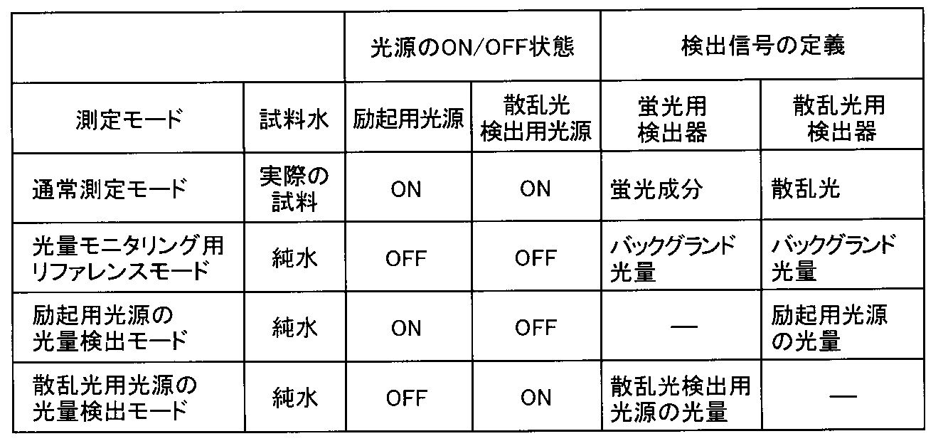
図3Aに示すように、試料水測定時には表1の通常測定モードが選択され、蛍光強度及び濁度が測定される。試料セル5の試料水流路5a内には、実試料が通水される。励起用の光源11、散乱光検出用の光源31は共にONの状態にされる。励起用の光源11からは、励起用の光源光L1が発せられ、試料セル5の試料水に照射される。試料水中の検出対象成分は、光源光L1によって励起されて蛍光L2を発し、蛍光L2は蛍光検出器21の受光面21aに達する。また、光源光L1の一部は試料セル5を直進し、試料セル5を透過して透過光L1´として散乱光検出器41の受光面41aに達する。
散乱光検出用の光源31からは、散乱光検出用の光源光L3が発せられ、試料セル5の試料水に照射される。光源光L3は試料水中の微粒子成分により散乱され、散乱光L4は散乱光検出器41の受光面41aに達する。また、光源光L3の一部は試料セル5を直進し、試料セル5を透過して透過光L3´として蛍光検出器21の受光面21aに達する。以上のように、試料水測定時には、蛍光検出器21の受光面21aでは実試料の蛍光L2及び透過光L3´が検出され、散乱光検出器41の受光面41aでは実試料の散乱光L4及び透過光L1´が検出される。
このとき、試料セル5内で、散乱光照射光学系30の光軸B1と蛍光検出光学系20の光軸A2とを距離Dだけ離すことにより、光源光L3が試料セル5を透過した透過光L3´は、蛍光検出器21の受光面21aにおいて光軸A2から離れた位置に導入される。試料セル5内で、励起光照射光学系の光軸A1と散乱光検出光学系の光軸B2とを距離Dだけ離すことにより、光源光L1が試料セル5を透過した透過光L1´は、散乱光検出器41の受光面41aにおいて光軸B2から離れた位置に導入される。
これにより、蛍光検出光学系20に導入される透過光L3´の光量を調整できるため、蛍光検出器21で検出される透過光L3´の影響を抑えて、蛍光検出器21において蛍光L2を精度良く検出することができる。また、散乱光検出光学系40に導入される透過光L1´の光量を調整できるため、散乱光検出器41で検出される透過光L1´の光量の影響を抑えて、散乱光検出器41おいて散乱光L4を精度良く検出することができる。
図示は省略するが、バックグラウンド測定時には、光量モニタリング用リファレンスモードが選択され、光源11、31の光量モニタリング時のバックグランド光量が検出される。試料セル5には、蛍光成分及び散乱光成分を含まない水(純水)が通水される。励起用の光源11、散乱光検出用の光源31は共にOFFの状態であり、蛍光検出器21、散乱光検出器41でバックグランドの光量が検出される。一般的に検出器21、41は外部から遮光されているため、バックグランドの光量はほぼゼロになる。
図3Bに示すように、励起用の光源11の光量モニタリング時には、励起用光源の光量検出モードが選択され、光源11の透過光L1´が検出される。試料セル5の試料水流路5a内には、純水が通水される。励起用の光源11はON、散乱光検出用の光源31はOFFの状態にされる。光源11から発せられた光源光L1は、試料セル5に照射される。光源光L1は試料セル5を透過して、透過光L1´として散乱光検出器41の受光面41aに達し、透過光L1´が検出される。散乱光検出光学系40(図1参照)は励起光照射光学系10(図1参照)に対向して配置されているため、透過光L1´を検出することができ、専用の光量検出器を設けることなく光源11の光量モニタリングをすることができる。
図3Cに示すように、散乱光検出用の光源31の光量モニタリング時には、散乱光検出用光源の光量検出モードが選択され、光源31の透過光L3´が検出される。試料セル5の試料水流路5a内には、純水が通水される。励起用の光源11はOFF、散乱光検出用の光源31はONの状態にされる。光源31から発せられた光源光L3は、試料セル5に照射される。光源光L3は試料セル5を透過して、透過光L3´として蛍光検出器21の受光面21aに達し、透過光L3´が検出される。蛍光検出光学系20(図1参照)は散乱光照射光学系30(図1参照)に対向して配置されているため、透過光L3´を検出することができ、専用の光量検出器を設けることなく、光源31の光量モニタリングをすることができる。
光源11、31の光量をモニタリングすることにより、光源11、31の劣化による光量の低下を検出し、光量を一定にするフィードバッグ制御を行うことや、モニタリングした光量を用いて予め求めた所定光量時の検出感度を推測し、補正処理を行うことが可能になる。
以上のように、第1の実施の形態に係る水質分析計1は、励起光照射光学系10の光軸A1と蛍光検出光学系20の光軸A2との交点P1と、散乱光照射光学系30の光軸B1と散乱光検出光学系40の光軸B2との交点P2とを試料セル5内で離間させて距離Dを調整する。これにより、試料水測定時には、蛍光検出器21において、透過光L3´の影響を抑えながら、蛍光L2を精度良く検出することができ、散乱光検出器41において、透過光L1´の影響を抑えながら、散乱光L4を精度良く検出することができる。また、励起用の光源11の光量モニタリング時には、散乱光検出器41で透過光L1´の光量を検出することができるため、専用の光量検出器を設けることなく、散乱光検出光学系40において励起用の光源11の光量モニタリングをすることができる。散乱光検出用の光源31の光量モニタリング時には、蛍光検出器21で透過光L3´の光量を検出することができるため、専用の光量検出器を設けることなく、蛍光検出光学系20において散乱光検出用の光源31の光量モニタリングをすることができる。これにより、励起用の光源11及び散乱光検出用の光源31の光量の低下を考慮して安定した水質分析を行うことができる。
ここで、水質分析計は、上下水道における水や、海水、河川水、湖沼水等の環境水、排水等の試料水を対象として、試料水中の特定成分に励起光を照射し、特定成分から放出される蛍光を検出して、特定成分を測定する。一般に、試料水に含まれる懸濁物質の濃度が増加すると、励起光が懸濁物質による散乱、吸収等の影響を受けて、特定成分の蛍光強度が変動することが知られており、特定成分の蛍光強度を正確に測定するためには、濁度を測定して蛍光強度を補正する必要がある。
しかしながら、励起光と、濁度測定に用いる散乱光検出用の光とは、波長帯が異なる。試料水によって、この2つの異なる波長帯における光の吸収特性は異なるため、濁度による蛍光強度の補正のみでは、正確に試料水の特定成分の蛍光を測定できない場合がある。すなわち、試料水における懸濁物質の濃度が同じであっても、懸濁物質の種類が異なると、懸濁物質における励起光及び蛍光の吸収特性が異なるため、濁度による補正のみでは蛍光を正確に補正できない。このため、試料水の蛍光強度から吸光度を測定し、励起光と濁度測定用の照射光の2波長の試料水における吸収度合を検出し、特定成分の蛍光強度を補正する必要がある。
さらに試料水の特定成分から放出される蛍光も、試料水の吸収によって減少する。蛍光の波長は、一般に励起光及び濁度測定用の照射光の波長と異なる。蛍光の波長における吸収特性を検出するためには、励起光の波長と濁度測定用の照射光の波長の他に、さらに蛍光の波長における吸光度を検出する必要がある。よって、試料水に蛍光を照射する光源と、この光源光を検出する検出器等を水質分析計に設ける必要があるため、水質分析計の構成が複雑化してしまう。
このように特定成分の蛍光強度を正確に測定するためには、試料水の濁度及び懸濁物質の種類により生じる影響を考慮して、特定成分の蛍光強度を補正する必要がある。従来の補正方法としては、試料水の2波長における吸光度を用いて特定波長における吸光度を補正することにより、試料水中の濁度や懸濁物質の種類の影響を抑えて特定成分を測定する方法が知られているが、用いられる水質分析装置に蛍光を検出する機能がないため、蛍光を発する成分を検出できなかった。また、試料水のラマン散乱光を利用して特定成分の蛍光強度を補正することにより、懸濁物質により生じる影響を抑える方法が知られているが、濁度を測定することができなかった。
そこで、第2の実施の形態に係る水質分析計においては、蛍光検出機能と濁度検出機能を有するとともに、透過光検出光学系により、励起光が試料水を透過した透過光及び濁度測定用の照射光が試料水を透過した透過光を検出する。励起光が試料水を透過した透過光から励起光の波長における吸収特性を、濁度測定用の照射光が試料水を透過した透過光から濁度測定用の照射光の波長における吸収特性を検出し、これを用いて蛍光の波長における吸収特性を予測して蛍光強度を補正する。これにより、照射または検出する光の波長を増やすことなく試料水中の特定成分が放出した蛍光を正確に測定できる。
以下、第2の実施の形態に係る水質分析計について詳細に説明する。第2の実施の形態では、励起用の光源光が試料セルを透過した透過光及び散乱光検出用の光源光が試料セルを透過した透過光を透過光検出光学系で検出する。そして、予測部において、透過光強度から試料水の励起用の光源光の波長における吸光度及び散乱光検出用の光源光の波長における吸光度を算出し、これらの吸光度から蛍光の波長における吸光度を予測する。
図4は、第2の実施の形態に係る水質分析計の概略構成図である。図5は、上記実施の形態に係る制御部の構成を示すブロック図である。水質分析計2は、試料セル50を中心にして4方向に透過光検出光学系100、蛍光検出光学系70、濁度検出用の散乱光照射光学系80及び散乱光検出光学系90を備えている。蛍光検出光学系70と散乱光検出光学系90とは、試料セル50を挟んで対向して配置され、散乱光照射光学系80と透過光検出光学系100とは、試料セル50を挟んで対向して配置されている。また、散乱光照射光学系80と試料セル50との間にはハーフミラー(光学部材)55が備えられており、光学部材55の側方には励起光照射光学系60が配設されている。光学部材55は後述する励起用の光源光L1及び散乱光検出用の光源光L3を試料セル50に導く位置に配置される。光学部材55と透過光検出光学系100は、試料セル50を挟んで対向している。
励起光照射光学系60は、励起用の光源61と、光源61と光学部材55との間に配置されたコリメートレンズ62とを有している。蛍光検出光学系70は、蛍光検出器71と、蛍光検出器71と試料セル50との間に配置された集光レンズ72、光学フィルタ73、集光レンズ74とを有している。集光レンズ72、74は、光学フィルタ73に対称に配置されている。また、散乱光照射光学系80は、散乱光検出用の光源81と、光源81と光学部材55との間に配置されたコリメートレンズ82とを有している。散乱光検出光学系90は、散乱光検出器91と、散乱光検出器91と試料セル50との間に配置された集光レンズ92、93とを有している。また、透過光検出光学系100は、透過光検出器101と、試料セル50との間に配置された集光レンズ102とを有している。
試料セル50は、中心に試料水流路50aを有する角筒状に形成されており、透過光検出光学系100の光軸E、蛍光検出光学系70の光軸C1、散乱光照射光学系80の光軸D1及び散乱光検出光学系90の光軸D2に対して垂直方向に延びている。試料水流路50aには測定対象となる試料水が通水される。試料セル50としては、石英ガラス等の透明部材から成るフローセルが用いられるが、石英ガラスから成る角型セルを用いることもできる。
また、励起用の光源61としては、波長λ1の光を発することができる発光ダイオード、レーザーダイオード等を用いることができる。散乱光検出用の光源81としては、波長λ2の光を発することができる発光ダイオード、レーザーダイオード等を用いることができる。励起用の光源光L1の波長λ1は、250nm以上350nm以下であることが好ましく、散乱光検出用の光源光L3の波長λ2は、600nm以上900nm以下であることが好ましい。
また、散乱光検出器91としては、散乱光検出用の光源光L3の波長λ2の光を検出範囲に含むシリコンフォトダイオード等を用いることができる。また、蛍光検出器71としては、光電子増倍管等を用いることができ、これにより光学フィルタ73を選択的に透過した蛍光の特定波長λ3の微少な蛍光を検出することができる。光学フィルタ73としては、特に限定されないが、目的とする検出対象成分が放出する波長λ3の蛍光だけを選択的に透過させるバンドパスフィルタ等を用いることができ、これにより波長λ3以外の光がカットされる。特定波長λ3としては、蛍光検出器71による検出効率を上げる観点から、蛍光のピーク波長が選択されることが好ましい。また、波長λ3は、波長λ1以上波長λ2以下であることが好ましい。これにより、後述する予測部で精度良く波長λ3における吸光度を予測することができる。また、透過光検出器101としては、励起用の光源光L1の波長λ1、散乱光検出用の光源光L3の波長λ2の光を検出範囲に含むシリコンフォトダイオード等を用いることができる。また、光学部材55としては、ハーフミラー、ビームスプリッター等を用いることができる。
このような構成において、試料水測定時には、励起用の光源61及び散乱光検出用の光源81を交互に点灯させる。試料セル50の試料水流路50a内には、実試料が通水される。励起用の光源61からは、波長λ1の励起用の光源光L1が発せられ、光源光L1はコリメートレンズ62を通って近平行光(コリメート光)となり、光学部材55によって反射され、試料セル50の試料水に照射される。試料水中の検出対象成分は、光源光L1によって励起されて蛍光L2を発する。蛍光L2は、集光レンズ72により集光され、光学フィルタ73に到達し、光学フィルタ73により特定波長λ3の光L2´が取り出された後に、集光レンズ74によって集光され、蛍光検出器71の受光面71aに達する。また、光源光L1の一部は試料セル50を直進し、試料セル50を透過して透過光L1´として集光レンズ102によって集光され透過光検出器101の受光面101aに達する。
散乱光検出用の光源81からは、波長λ2の散乱光検出用の光源光L3が発せられ、光源光L3はコリメートレンズ82を通って近平行光となり、光学部材55を通過して試料セル50の試料水に照射される。光源光L3は試料水中の懸濁物質としての微粒子成分により散乱され、散乱光L4が発せられる。散乱光L4は、集光レンズ92、93によって集光され、散乱光検出器91の受光面91aに達する。また、光源光L3の一部は試料セル50を直進し、試料セル50を透過して透過光L3´として集光レンズ102により集光され透過光検出器101の受光面101aに達する。
このように水質分析計2では、試料水測定時に、励起用の光源61から試料セル50に波長λ1の励起用の光源光L1が照射され、光源光L1の照射により励起された試料水中の特定成分が放出する波長λ3の蛍光L2を蛍光検出器71で検出することで蛍光強度が測定される。同時に、散乱光検出用の光源81から試料セル50に波長λ2の散乱光検出用の光源光L3が照射され、光源光L3の照射により試料水中の微粒子で散乱された散乱光L4を散乱光検出器91で検出することで濁度が測定される。散乱光を検出しながら蛍光を検出しているため、濁度の影響を考慮しながら試料水中の検出対象となる特定成分の蛍光強度を測定することができる。
光学部材55で反射された励起用の光源光L1の進行方向光と蛍光検出光学系70の光軸C1とは、直交している。このため、透過光L1´が蛍光検出器71へ導入されることを抑えながら、蛍光検出器71で試料水中の特定成分から発せられた蛍光L2´を検出することができる。また、散乱光照射光学系80の光軸D1と散乱光検出光学系90の光軸D2とは、直交している。このため、透過光L3´が散乱光検出器91へ導入されること抑えながら、散乱光検出器91で試料水中の微粒子から発せられた散乱光L4を検出することができる。
また、水質分析計2において、透過光検出光学系100は、試料セル50を挟んで光学部材55に対向しており、励起用の光源光L1及び散乱光検出用の光源光L3を試料セル50に導くように配置されている。このため、試料水測定時に、励起用の光源61から照射された波長λ1の励起用の光源光L1が光学部材55で反射され試料セル50に導入され、試料セル50を透過した透過光L1´を透過光検出器101で検出することができる。また、散乱光検出用の光源81から照射された波長λ2の散乱光検出用の光源光L3が光学部材55を通過して試料セル50に導入され、試料セル50を透過した透過光L3´を蛍光検出器71で検出することができる。このようにして検出された透過光L1´、L3´の強度を用い、後述する予測部121(図5参照)において試料セル50に実試料を通水させた場合と純水を通水させた場合における透過光の強度の比を算出することで、実試料の吸光度を求めることができる。
また、図5に示すように、水質分析計2には、各部を統括制御する制御部120が設けられている。制御部120は後述する蛍光検出モードと濁度検出モードを切り替えることにより、励起用の光源61及び散乱光検出用の光源81の点灯及び消灯が繰り返される。制御部120は、各種処理を実行するプロセッサやメモリ等により構成される。メモリは、用途に応じてROM(Read Only Memory)、RAM(Random Access Memory)等の一つ又は複数の記憶媒体で構成される。制御部120には、予測部121、濁度補正部122及び吸光度補正部123が設けられている。なお、制御部120は、制御回路、制御器、制御装置等で構成されていてもよい。
予測部121では、透過光検出器101で検出された透過光L1´から波長λ1の励起用の光源光L1における試料水の吸光度が算出され、透過光L3´から波長λ2の散乱光検出用の光源光L3における試料水の吸光度が算出される。波長λ1及び波長λ2における試料水の吸光度から波長λ3の蛍光における試料水の吸光度が予測される。なお、予測部121は、予測回路、予測器、予測装置等で構成されていてもよい。濁度補正部122では、散乱光検出器91で検出された波長λ2の散乱光L4より測定された濁度を用いて、蛍光検出器71で検出された試料水の蛍光の強度を補正することにより、蛍光強度を濁度補正する。なお、濁度補正部122は、濁度補正回路、濁度補正器、濁度補正装置等で構成されていてもよい。吸光度補正部123では、予測部121において算出された波長λ1における試料水の吸光度と、予測された波長λ3の吸光度とを用いて、濁度補正部122で濁度補正された蛍光強度を補正することにより、吸光度補正された蛍光強度が算出される。なお、吸光度補正部123は、吸光度補正回路、吸光度補正器、吸光度補正装置等で構成されていてもよい。このように、水質分析計2では、波長λ1及び波長λ2における試料水の吸光度から波長λ3の吸光度を予測する。これにより、波長λ3の光を照射する光源等を設置して試料水の波長λ3における吸光度を実測し、実測値を用いて蛍光強度を補正する必要がないため、水質分析計2を簡易な構成とすることができる。
次に、図6及び表2を参照して、上記実施の形態に係る水質分析計2による試料水の測定動作について説明する。図6は、上記実施の形態に係る通常測定モードの水質分析計の測定動作の説明図である。図6Aは、上記実施の形態に係る実試料の蛍光強度及び励起光用の光源光の透過光の測定動作の説明図である。図6Bは、上記実施の形態に係る実試料の散乱光強度及び散乱光検出用の光源光の透過光の測定動作の説明図である。図7は、上記実施の形態に係る純水測定モードの水質分析計の測定動作の説明図である。図7Aは、上記実施の形態に係る純水の励起光用の光源光の透過光の測定動作の説明図である。図7Bは、上記実施の形態に係る純水の散乱光検出用の光源光の透過光の測定動作の説明図である。図8は、懸濁物質を含む試料水の吸光度測定の例を示す図である。なお、図8において、横軸は波長、縦軸は吸光度をそれぞれ示している。また、表2の通常測定モード及び純水測定モードにおいては蛍光検出モードと濁度検出モードの2つの測定モードがそれぞれ記載され、通常測定モードと純水測定モード、蛍光検出モードと濁度検出モードは制御部120(図5参照)により切り替えられる。
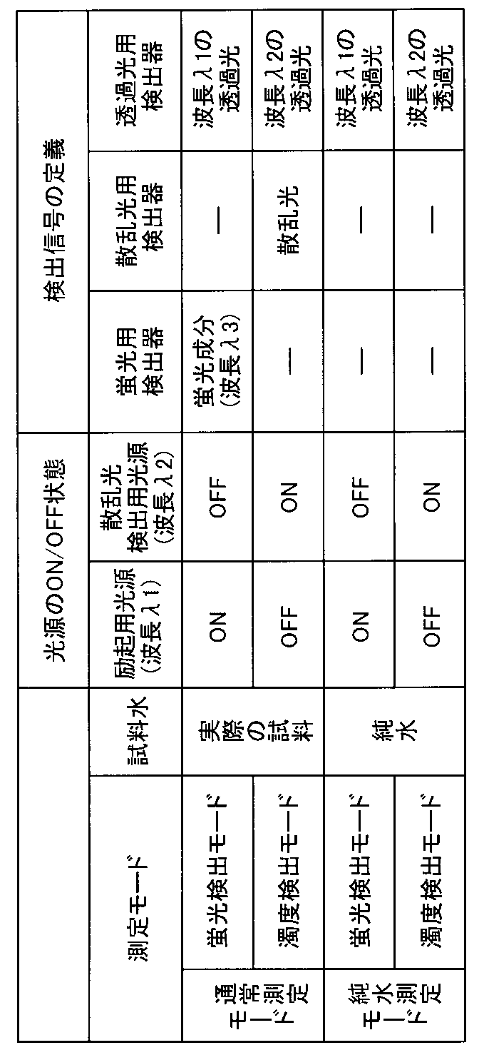
図6に示すように、実試料測定時には表2の通常測定モードが選択され、試料セル50の試料水流路50a内には、実試料が通水される。図6Aに示すように、実試料中の検出対象となる特定成分の蛍光L2´強度及び励起用の光源光L1が試料セル50を透過した透過光L1S´を測定する際には、通常測定モードにおける蛍光検出モードが選択され、蛍光L2の強度及び透過光L1S´の強度が測定される。励起用の光源61はON、散乱光検出用の光源81はOFFの状態にされる。励起用の光源61からは、波長λ1の励起用の光源光L1が発せられ、光学部材55で反射されて試料セル50の実試料に照射される。実試料中の検出対象成分は、光源光L1によって励起されて、励起用の光源光L1の波長λ1よりも長波長側にピークを持つ蛍光L2を発し、蛍光L2は光学フィルタ73により特定波長λ3の光L2´が取り出された後に、蛍光検出器71の受光面71aに達する。また、光源光L1の一部は試料セル50を直進し、試料セル50を透過して透過光L1S´として透過光検出器101の受光面101aに達する。
図6Bに示すように、試料水の散乱光L4強度及び散乱光検出用の光源光L3が試料セル50を透過した透過光L3S´を測定する際には、表2の通常測定モードにおける濁度検出モードが選択され、散乱光L4の強度及び透過光L3S´の強度が測定される。励起用の光源61はOFF、散乱光検出用の光源81はONの状態にされる。散乱光検出用の光源81からは、波長λ2の散乱光検出用の光源光L3が発せられ、光学部材55を通過して試料セル50の実試料に照射される。光源光L3は実試料中の微粒子成分により散乱され、散乱光L4は散乱光検出器91の受光面91aに達する。また、光源光L3の一部は試料セル50を直進し、試料セル50を透過して透過光L3S´として透過光検出器101の受光面101aに達する。
以上のように、蛍光検出モードでは、蛍光検出器71で波長λ3の実試料の蛍光成分L2´が検出され、透過光検出器101で透過光L1S´が検出される。また、濁度測定モードでは、散乱光検出器91で実試料の散乱光L4が検出され、透過光検出器101で透過光L3S´が検出される。透過光検出器101には、励起用の光源光L1の透過光L1S´及び散乱光検出用の光源光L3の透過光L3S´の2種類の光が到達する。水質分析計2では、制御部120(図5参照)により蛍光検出モードと濁度検出モードを切り替えることにより、励起用の光源61及び散乱光検出用の光源81の点灯、消灯を交互に繰り返している。これにより、透過光検出器101で検出される透過光L1S´と透過光L3S´の検出信号を分離している。
また、図7に示すように、純水測定時には表2の純水測定モードが選択され、試料セル50の試料水流路50a内には、純水が通水される。図7Aに示すように、励起用の光源光L1が試料セル50の純水を透過した透過光L10´を測定する際には、純水測定モードにおける蛍光検出モードが選択され、透過光検出器101で透過光L10´の強度が検出される。励起用の光源61はON、散乱光検出用の光源81はOFFの状態にされる。励起用の光源61から発せられた波長λ1の光源光L1は、光学部材55で反射されて試料セル50の純水に照射される。光源光L1は試料セル5を透過して、透過光L10´として透過光検出器101の受光面101aに達し、透過光L10´が検出される。
図7Bに示すように、散乱光検出用の光源81が試料セル50の純水を透過した透過光L30´を測定する際には、純水測定モードにおける濁度検出モードが選択され、透過光検出器101で透過光L30´の強度が検出される。励起用の光源61はOFF、散乱光検出用の光源81はONの状態にされる。散乱光検出用の光源81から発せられた波長λ2の光源光L3は、光学部材55を透過して試料セル50の純水に照射される。光源光L3は試料セル50を透過して、透過光L30´として透過光検出器101の受光面101aに達し、透過光L30´が検出される。
予測部121(図5参照)では、透過光検出器101で検出された励起用の光源光L1の透過光L1S´、L10´、散乱光検出用の光源光L3のL3S´、L30´を用いて、試料水の吸光度合を表す吸光度を算出する。試料水として、懸濁物質を含まない純水を用いた場合の透過光強度をI0とし、懸濁物質を含む実試料の透過光強度をISとすると、実試料の吸光度(ABS)は下記の式(1)で表される。
ABS = -log(IS/I0) (1)
ABS = -log(IS/I0) (1)
予測部121では、式(1)を用いて、通常測定モードにおける蛍光検出モードで検出された透過光L1S´と、純水測定モードにおける蛍光検出モードで検出された透過光L10´から、波長λ1の励起用の光源光L1における実試料の吸光度Aλ1が算出される。また、通常測定モードにおける濁度検出モードで検出された透過光L3S´と、純水測定モードにおける濁度検出モードで検出された透過光L30´から、波長λ2の散乱光検出用の光源光L3における実試料の吸光度Aλ2が算出される。水質分析計2では、制御部120(図5参照)で純水測定モードを選択して、純水における励起用の光源光L1の透過光L10´、散乱光検出用の光源光L3の透過光L30´を、予めもしくは定期的に測定しておく。これにより、通常測定モードで実試料の透過光L1S´、L3S´の強度を検出した際に、波長λ1及び波長λ2における実試料の吸光度Aλ1、Aλ2を算出することができる。
ここで、懸濁物質の種類と試料水の吸収特性について説明する。試料水における懸濁物質の濃度、すなわち濁度が同じであっても、懸濁物質の種類が異なると懸濁物質における励起光及び蛍光の吸収特性は異なる。図8において、実線は白色の懸濁溶液、破線は黒色の懸濁溶液の吸収スペクトルを示している。2種類の懸濁溶液において、散乱光測定による濁度は同じであるが、懸濁物質の種類が異なるため吸収スペクトルは大きく異なった。白色の懸濁物質を含む試料水の吸光度は、短波長側で大きく、長波長側で小さくなる傾向を示した。一方、黒色の懸濁物質を含む試料水の吸光度は、短波長から長波長にかけて同程度の大きさとなる波長の範囲が広かった。なお、所定の波長の光において、吸光度が大きいほど試料水による光の吸収が大きくなるため、検出対象成分の濃度が同じ試料水同士であっても、蛍光検出器71で検出される蛍光強度は小さくなる。
試料水中に含まれている懸濁物質の種類によって短波長側の吸光度と長波長側の吸光度の絶対値とその比率は大きく異なる。このため、短波長側の吸光度と長波長側の吸光度の絶対値とその比率から、その間の特定波長、すなわち蛍光波長の吸光度を予測することができる。特定波長における吸光度の予測には、線形近似法等を用いることができる。
励起用の光源光L1の波長λ1を紫外領域である短波長側の例えば250nm以上350nm以下にすると、実試料中の検出対象成分である有機物や油分等の蛍光はピーク波長として例えば350nm以上500nm以下の付近に出現する。すなわち、試料水中の特定成分が放出する波長λ3の蛍光である。一方、濁度の測定に用いられる散乱光検出用の光源光L3の波長λ2としては、長波長側の例えば600nm以上900nm以下の可視光から近赤外光が用いられる。
予測部121においては、実測された透過光L1S´、L10´から波長λ1の励起用の光源光L1における実試料の吸光度Aλ1及び実測された透過光L3S´、L30´から波長λ2の散乱光検出用の光源光L3における実試料の吸光度Aλ2が算出される。予測部121では、短波長λ1側の吸光度Aλ1と長波長λ2側の吸光度Aλ2の絶対値とその比率から、波長λ1と波長λ2の間の波長λ3における蛍光の吸光度Aλ3を予測する。波長λ3は、蛍光スペクトルのピーク波長であることが好ましい。
また、濁度補正部122(図5参照)では、散乱光検出器91で検出された波長λ2の散乱光L4の強度が懸濁物質の濃度に比例することを利用して測定される濁度を用いて、蛍光検出器71で検出された試料水の蛍光L2´の強度を補正することにより、蛍光強度を濁度補正する。濁度補正は、式(2)に示す濁度補正式を用いて行われる。濁度をX、蛍光検出器71で検出した蛍光強度をF0とすると、濁度補正後の蛍光強度F1は、式(2)で表される。
F1 = (aX2+bX+c)×F0 (2)
a,b,c:定数
F1 = (aX2+bX+c)×F0 (2)
a,b,c:定数
予測部121で算出された波長λ1における吸光度Aλ1及び予測された波長λ3における実試料の吸光度Aλ3と、濁度補正部122で濁度補正された蛍光強度をF1は、吸光度補正部123(図5参照)に出力される。吸光度補正部123では、波長λ1における実試料の吸光度Aλ1と予測された波長λ3の吸光度Aλ3とを用いて、濁度補正された蛍光強度F1を補正することにより、吸光度補正された蛍光強度を算出する。吸光度補正は、式(3)を用いて行われる。吸光度補正後の蛍光強度F2は、式(3)で表される。
F2 = k×F1×exp((Aλ1+Aλ3)/2) (3)
k:定数
F2 = k×F1×exp((Aλ1+Aλ3)/2) (3)
k:定数
このように、実測した透過光L1S´、L10´及びL3S´、L30´から算出された波長λ1、λ2における実試料の吸光度Aλ1、Aλ2から波長λ3における吸光度Aλ3を予測し、蛍光強度を吸光度補正することにより、実試料の励起光及び蛍光の吸収特性の影響を考慮することができる。このため、懸濁物質の種類によらず、検出対象成分の蛍光強度を正確に測定することができる。また、波長λ3の蛍光の吸収特性を検出するための蛍光を照射する光源等が必要ないため、水質分析計2を簡易な構成とすることができる。
以上のように、第2の実施形態に係る水質分析計2は、第1の波長λ1の励起用の光源光L1の透過光L1´及び第2の波長λ2の散乱光検出用の光源光L3の透過光L3´によって第1の波長λ1、第2の波長λ2における試料水の吸光度Aλ1、Aλ2を算出する。これらの吸光度Aλ1、Aλ2を用いて第3の波長λ3の蛍光における吸光度Aλ3を予測して、第3の波長λ3の蛍光における吸光度Aλ3を測定対象成分の蛍光強度の補正に用いる。これにより、蛍光強度を精度良く測定できるとともに、蛍光強度の補正のために第3の波長λ3の光を照射する光源と、この光源光の透過光を検出する検出器等を水質分析計2に設けて、試料水の第3の波長λ3における吸光度を測定する必要がないため、水質分析計2を簡易な構成とすることができる。
なお、本発明は第1及び第2実施の形態に限定されず、種々変更して実施することが可能である。上記実施の形態において、添付図面に図示されている大きさや形状などについては、これに限定されず、本発明の効果を発揮する範囲内で適宜変更することが可能である。その他、本発明の目的の範囲を逸脱しない限りにおいて適宜変更して実施することが可能である。
例えば、第1の実施の形態においては、各光学系10、20、30、40の配置は、蛍光検出光学系20が、散乱光照射光学系30の光量を検出可能で且つ、散乱光検出光学系40が、励起光照射光学系10の光量を検出可能であるように配置されていれば、特に限定されない。
また、第1の実施の形態においては、各光学系10、20、30、40の構成は、蛍光L2及び透過光L3´が蛍光検出器21の受光面21aに導入され、散乱光L4及び透過光L1´が散乱光検出器41の受光面41aに導入されれば、特に限定されない。
また、第1の実施の形態においては、励起光照射光学系10、散乱光照射光学系30において、コリメートレンズ12、32を含む構成としたが、光源11、31に予めレンズが組み込まれており近平行光を形成できる光源を用いれば、コリメートレンズ12、32は含まれなくてもよい。
また、第1の実施の形態においては、試料セル5は角筒状に形成されている構成としたが、蛍光検出器21で蛍光L2及び透過光L3´が検出され、散乱光検出器41で散乱光L4及び透過光L1´が検出される形状であれば、この構成に限定されない。
例えば、第2の実施の形態においては、各光学系60、70、80、90、100の配置は、透過光検出光学系100が、散乱光照射光学系80の光量を検出可能で且つ、励起光照射光学系60の光量を検出可能であるように配置されていれば、特に限定されない。
また、第2の実施の形態においては、各光学系60、70、80、90、100の構成は、蛍光L2´が蛍光検出器71の受光面71aに導入され、散乱光L4が散乱光検出器91の受光面91aに導入され、透過光L1´、L3´が透過光検出器101の受光面101aに導入されれば、特に限定されない。
また、第2の実施の形態においては、励起光照射光学系60、散乱光照射光学系80において、コリメートレンズ62、82を含む構成としたが、光源61、81に予めレンズが組み込まれており近平行光を形成できる光源を用いれば、コリメートレンズ62、82は含まれなくてもよい。
また、第2の実施の形態においては、試料セル50は角筒状に形成されている構成としたが、蛍光検出器71で蛍光L2´が検出され、散乱光検出器41で散乱光L4が検出され、透過光検出器101で透過光L1´、L3´が検出される形状であれば、この構成に限定されない。
また、第2の実施形態における実測した波長λ1、λ2における吸光度Aλ1、Aλ2から波長λ3における吸光度Aλ3を予測し、これを用いて蛍光強度を吸光度補正する構成を、第1の実施形態に適用してもよい。この場合、試料セル5に実試料を通水した場合と純水を通水した場合における、蛍光検出器21で検出される波長λ2の散乱光検出用の光源31の透過光L3´より、波長λ2における吸光度Aλ2が算出される。また、散乱光検出器41で検出される波長λ1の励起用の光源11の透過光L1´より、波長λ1における吸光度Aλ1が算出される。これらにより波長λ3における吸光度Aλ3を予測できる。
下記に上記実施の形態における特徴点を整理する。
本発明の水質分析計は、測定対象となる試料水に励起用の光源光を照射する励起光照射光学系と、前記励起用の光源光の照射により励起された試料水中の特定成分の蛍光を検出する蛍光検出光学系と、試料水に散乱光検出用の光源光を照射する散乱光照射光学系と、前記散乱光検出用の光源光の照射により試料水中の微粒子で散乱された散乱光を検出する散乱光検出光学系と、を有し、前記励起光照射光学系の光量及び前記散乱光照射光学系の光量を検出可能であることを特徴とする。
本発明の水質分析計は、測定対象となる試料水に励起用の光源光を照射する励起光照射光学系と、前記励起用の光源光の照射により励起された試料水中の特定成分の蛍光を検出する蛍光検出光学系と、試料水に散乱光検出用の光源光を照射する散乱光照射光学系と、前記散乱光検出用の光源光の照射により試料水中の微粒子で散乱された散乱光を検出する散乱光検出光学系と、を有し、前記励起光照射光学系の光量及び前記散乱光照射光学系の光量を検出可能であることを特徴とする。
本発明の水質分析計においては、前記蛍光検出光学系が、前記散乱光照射光学系の光量を検出可能で且つ、前記散乱光検出光学系が、前記励起光照射光学系の光量を検出可能であるように配置されている。
この構成により、試料水測定時には、散乱光検出光学系で散乱光を検出しながら蛍光検出光学系で蛍光を検出しているため、試料水の濁度の影響を考慮しながら、試料水の蛍光強度を精度良く測定することができる。また、励起用の光源の光量モニタリング時には、散乱光検出光学系が励起用の光源の光量も検出することができるため、専用の光量検出器を設けることなく、散乱光検出光学系において励起用の光源の光量モニタリングをすることができる。散乱光検出用の光源の光量モニタリング時には、蛍光検出光学系が散乱光検出用の光源の光量も検出することができるため、専用の光量検出器を設けることなく、蛍光検出光学系において散乱光検出用の光源の光量モニタリングをすることができる。これにより、励起用の光源及び散乱光検出用の光源の光量の低下を考慮して安定した水質分析を行うことができる。
本発明の水質分析計においては、前記励起光照射光学系と前記散乱光検出光学系が、試料水通水容器を挟んで対向しており、前記散乱光照射光学系と前記蛍光検出光学系が、前記試料水通水容器を挟んで対向している。この構成により、励起光照射光学系と散乱光検出光学系とが対向しているため、励起用の光源光の試料水通水容器を透過した透過光の光量を検出することができる。散乱光照射光学系と蛍光検出光学系とが対向しているため、散乱光検出用の光原光の試料水通水容器を透過した透過光の光量を検出することができる。これにより、各光源の光量モニタリングをすることができる。
本発明の水質分析計においては、前記試料水通水容器内の中心で、前記励起光照射光学系の光軸と前記蛍光検出光学系の光軸とが垂直に交差し、前記散乱光照射光学系の光軸と前記散乱光検出光学系の光軸とが垂直に交差している。この構成により、励起用の光源光の試料水通水容器を透過した透過光の影響を抑えながら、蛍光検出光学系で試料水中の特定成分の蛍光を検出することができる。散乱光検出用の光源光の試料水通水容器を透過した透過光の影響を抑えながら、散乱光検出光学系で試料水中の微粒子から発せられた散乱光を検出することができる。
本発明の水質分析計においては、前記励起光照射光学系の光軸と前記蛍光検出光学系の光軸との第1の交点と、前記散乱光照射光学系の光軸と前記散乱光検出光学系の光軸との第2の交点とが、前記試料水通水容器内で離間している。この構成により、散乱光照射光学系の光軸と蛍光検出光学系の光軸との距離が離れているため、試料測定時に、蛍光検出光学系において、散乱光検出用の光源光の試料水通水容器を透過した透過光の影響を抑えながら、励起用の光源光の検出機能の精度を保つことができる。励起光照射光学系の光軸と散乱光検出光学系の光軸との距離が離れているため、試料測定時に、散乱光検出光学系において、励起用の光源光の試料水通水容器を透過した透過光の影響を抑えながら、散乱光検出用の光源光の検出機能の精度を保つことができる。
本発明の水質分析計においては、前記第1の交点と前記第2の交点との距離が、0mmより大きく10mm以下であることが好ましい。この構成により、試料測定時に、蛍光検出光学系及び散乱光検出光学系のそれぞれにおいて導入される散乱光検出用の光源光の試料水通水容器を透過した透過光及び励起用の光源光の試料水通水容器を透過した透過光の光量の影響を効果的に抑えることができる。
本発明の水質分析計においては、前記励起用の光源光が試料水を透過した第1の透過光から前記励起用の光源光の第1の波長における試料水の吸光度を算出し、前記散乱光検出用の光源光が試料水を透過した第2の透過光から前記散乱光検出用の光源光の第2の波長における試料水の吸光度を算出し、前記第1の波長及び前記第2の波長における試料水の吸光度から前記蛍光の第3の波長における試料水の吸光度を予測する予測部を有する。この構成により、第1の波長の励起用の光源光の透過光及び第2の波長の散乱光検出用の光源光の透過光によって第1の波長、第2の波長における試料水の吸光度を算出する。これらの吸光度を用いて第3の波長の蛍光における吸光度を予測して、第3の波長の蛍光における吸光度を測定対象成分の蛍光強度の補正に用いる。これにより、蛍光強度を精度良く測定できるとともに、蛍光強度の補正のために第3の波長の光を照射する光源と、この光源光の透過光を検出する検出器等を水質分析計に設けて、試料水の第3の波長における吸光度を測定する必要がないため、水質分析計を簡易な構成とすることができる。
本発明の水質分析計においては、前記第3の波長における試料水の吸光度は、前記第1の波長及び前記第2の波長における試料水の吸光度の絶対値と比率から予測される。この構成により、試料水中に含まれている懸濁物質の種類に応じて、第3の波長における吸光度を精度良く予測することができる。
本発明の水質分析計においては、前記励起用の光源光が試料水を透過した第1の透過光及び前記散乱光検出用の光源光が試料水を透過した第2の透過光を検出する透過光検出光学系と、前記第1の透過光から前記励起用の光源光の第1の波長における試料水の吸光度を算出し、前記第2の透過光から前記散乱光検出用の光源光の第2の波長における試料水の吸光度を算出し、前記第1の波長及び前記第2の波長における試料水の吸光度から前記蛍光の第3の波長における試料水の吸光度を予測する予測部と、を有する。
この構成により、第1の波長の励起用の光源光の透過光及び第2の波長の散乱光検出用の光源光の透過光によって第1の波長、第2の波長における試料水の吸光度を算出する。これらの吸光度を用いて第3の波長の蛍光における吸光度を予測して、第3の波長の蛍光における吸光度を測定対象成分の蛍光強度の補正に用いる。これにより、蛍光強度を精度良く測定できるとともに、蛍光強度の補正のために第3の波長の光を照射する光源等を水質分析計に設けて、試料水の第3の波長における吸光度を測定する必要がないため、水質分析計を簡易な構成とすることができる。
本発明の水質分析計においては、前記第3の波長における試料水の吸光度は、前記第1の波長及び前記第2の波長における試料水の吸光度の絶対値と比率から予測される。この構成により、試料水中の微粒子の種類に応じて、第3の波長における吸光度を精度良く予測することができる。
本発明の水質分析計においては、前記第3の波長は、試料水中の前記特定成分の蛍光スペクトルのピーク波長である。この構成により、励起用の光源光により励起された試料水中の特定成分が放出する蛍光の検出効率を上げることができる。
本発明の水質分析計においては、前記散乱光検出光学系で検出された前記散乱光より測定された濁度を用いて、前記蛍光検出光学系で検出された前記蛍光の強度を補正することにより、濁度補正された蛍光強度を算出する濁度補正部を有する。この構成により、試料水の微粒子の濃度の影響を考慮して、試料水中の特定成分の蛍光強度を効果的に補正することができる。
本発明の水質分析計においては、前記第1の波長における試料水の吸光度と、前記予測部で予測される第3の波長における試料水の吸光度とを用いて、前記濁度補正された蛍光強度を補正することにより、吸光度補正された蛍光強度を算出する吸光度補正部を有する。この構成により、試料水の吸収特性の影響を考慮することができるため、試料水中の微粒子の種類によらず、特定成分の蛍光強度を正確に補正することができる。
本発明の水質分析計においては、前記第1の波長は250nm以上350nm以下であり、且つ前記第2の波長は600nm以上900nm以下であり、且つ前記第3の波長は前記第1の波長以上であり前記第2の波長以下であることが好ましい。この構成により、短波長側である第1の波長の吸光度と、長波長側である第2の波長の吸光度から、その間の第3の波長における吸光度を精度良く予測することができる。
本発明の水質分析計においては、前記励起用の光源光及び前記散乱光検出用の光源光を前記試料水通水容器に導く位置に配置される光学部材を備え、前記光学部材と前記透過光検出光学系が、前記試料水通水容器を挟んで対向している。この構成により、光学部材により、励起用の光源光及び散乱光検出用の光源光が試料水通水容器に導かれ、第1の透過光及び第2の透過光が適切に透過光検出光学系に導入される。
本出願は、2016年5月19日出願の特願2016-100435に基づく。この内容は、全てここに含めておく。
Claims (15)
- 測定対象となる試料水に励起用の光源光を照射する励起光照射光学系と、前記励起用の光源光の照射により励起された試料水中の特定成分の蛍光を検出する蛍光検出光学系と、試料水に散乱光検出用の光源光を照射する散乱光照射光学系と、前記散乱光検出用の光源光の照射により試料水中の微粒子で散乱された散乱光を検出する散乱光検出光学系と、を有し、
前記励起光照射光学系の光量及び前記散乱光照射光学系の光量を検出可能であることを特徴とする水質分析計。 - 前記蛍光検出光学系が、前記散乱光照射光学系の光量を検出可能で且つ、前記散乱光検出光学系が、前記励起光照射光学系の光量を検出可能であるように配置されていることを特徴とする請求項1に記載の水質分析計。
- 前記励起光照射光学系と前記散乱光検出光学系が、試料水通水容器を挟んで対向しており、前記散乱光照射光学系と前記蛍光検出光学系が、前記試料水通水容器を挟んで対向していることを特徴とする請求項2に記載の水質分析計。
- 前記試料水通水容器内の中心で、前記励起光照射光学系の光軸と前記蛍光検出光学系の光軸とが垂直に交差し、前記散乱光照射光学系の光軸と前記散乱光検出光学系の光軸とが垂直に交差していることを特徴とする請求項3に記載の水質分析計。
- 前記励起光照射光学系の光軸と前記蛍光検出光学系の光軸との第1の交点と、
前記散乱光照射光学系の光軸と前記散乱光検出光学系の光軸との第2の交点とが、前記試料水通水容器内で離間していることを特徴とする請求項4に記載の水質分析計。 - 前記第1の交点と前記第2の交点との距離が、0mmより大きく10mm以下であることを特徴とする請求項5に記載の水質分析計。
- 前記励起用の光源光が試料水を透過した第1の透過光から前記励起用の光源光の第1の波長における試料水の吸光度を算出し、前記散乱光検出用の光源光が試料水を透過した第2の透過光から前記散乱光検出用の光源光の第2の波長における試料水の吸光度を算出し、前記第1の波長及び前記第2の波長における試料水の吸光度から前記蛍光の第3の波長における試料水の吸光度を予測する予測部を有することを特徴とする請求項2に記載の水質分析計。
- 前記第3の波長における試料水の吸光度は、前記第1の波長及び前記第2の波長における試料水の吸光度の絶対値と比率から予測されることを特徴とする請求項7に記載の水質分析計。
- 前記励起用の光源光が試料水を透過した第1の透過光及び前記散乱光検出用の光源光が試料水を透過した第2の透過光を検出する透過光検出光学系と、前記第1の透過光から前記励起用の光源光の第1の波長における試料水の吸光度を算出し、前記第2の透過光から前記散乱光検出用の光源光の第2の波長における試料水の吸光度を算出し、前記第1の波長及び前記第2の波長における試料水の吸光度から前記蛍光の第3の波長における試料水の吸光度を予測する予測部と、を有することを特徴とする請求項1に記載の水質分析計。
- 前記第3の波長における試料水の吸光度は、前記第1の波長及び前記第2の波長における試料水の吸光度の絶対値と比率から予測されることを特徴とする請求項9に記載の水質分析計。
- 前記第3の波長は、試料水中の前記特定成分の蛍光スペクトルのピーク波長であることを特徴とする請求項9または請求項10に記載の水質分析計。
- 前記散乱光検出光学系で検出された前記散乱光より測定された濁度を用いて、前記蛍光検出光学系で検出された前記蛍光の強度を補正することにより、濁度補正された蛍光強度を算出する濁度補正部を有することを特徴とする請求項9または請求項10に記載の水質分析計。
- 前記第1の波長における試料水の吸光度と、前記予測部で予測される第3の波長における試料水の吸光度とを用いて、前記濁度補正された蛍光強度を補正することにより、吸光度補正された蛍光強度を算出する吸光度補正部を有することを特徴とする請求項12に記載の水質分析計。
- 前記第1の波長は250nm以上350nm以下であり、且つ前記第2の波長は600nm以上900nm以下であり、且つ前記第3の波長は前記第1の波長以上であり前記第2の波長以下であることを特徴とする請求項9または請求項10に記載の水質分析計。
- 前記励起用の光源光及び前記散乱光検出用の光源光を前記試料水通水容器に導く位置に配置される光学部材を備え、前記光学部材と前記透過光検出光学系が、前記試料水通水容器を挟んで対向していることを特徴とする請求項9または請求項10に記載の水質分析計。
Priority Applications (6)
| Application Number | Priority Date | Filing Date | Title |
|---|---|---|---|
| KR1020187011809A KR102444477B1 (ko) | 2016-05-19 | 2017-02-23 | 수질 분석계 |
| CN201780003869.3A CN108351304B (zh) | 2016-05-19 | 2017-02-23 | 水质分析仪 |
| JP2018518096A JP6436266B2 (ja) | 2016-05-19 | 2017-02-23 | 水質分析計 |
| EP17798949.8A EP3355048B1 (en) | 2016-05-19 | 2017-02-23 | Water quality analyzer |
| DK17798949.8T DK3355048T3 (da) | 2016-05-19 | 2017-02-23 | Vandkvalitetsanalysator |
| US15/968,409 US10302564B2 (en) | 2016-05-19 | 2018-05-01 | Water quality analyzer |
Applications Claiming Priority (2)
| Application Number | Priority Date | Filing Date | Title |
|---|---|---|---|
| JP2016-100435 | 2016-05-19 | ||
| JP2016100435 | 2016-05-19 |
Related Child Applications (1)
| Application Number | Title | Priority Date | Filing Date |
|---|---|---|---|
| US15/968,409 Continuation US10302564B2 (en) | 2016-05-19 | 2018-05-01 | Water quality analyzer |
Publications (1)
| Publication Number | Publication Date |
|---|---|
| WO2017199511A1 true WO2017199511A1 (ja) | 2017-11-23 |
Family
ID=60326246
Family Applications (1)
| Application Number | Title | Priority Date | Filing Date |
|---|---|---|---|
| PCT/JP2017/006951 Ceased WO2017199511A1 (ja) | 2016-05-19 | 2017-02-23 | 水質分析計 |
Country Status (7)
| Country | Link |
|---|---|
| US (1) | US10302564B2 (ja) |
| EP (1) | EP3355048B1 (ja) |
| JP (1) | JP6436266B2 (ja) |
| KR (1) | KR102444477B1 (ja) |
| CN (1) | CN108351304B (ja) |
| DK (1) | DK3355048T3 (ja) |
| WO (1) | WO2017199511A1 (ja) |
Cited By (8)
| Publication number | Priority date | Publication date | Assignee | Title |
|---|---|---|---|---|
| WO2020050488A1 (ko) * | 2018-09-04 | 2020-03-12 | 경북대학교 산학협력단 | 혈구 분석 장치, 이를 이용한 혈구 분석 방법 |
| JP2022516217A (ja) * | 2018-10-25 | 2022-02-25 | プレアー ソシエテ・アノニム | 液滴中の不純物を検出および/または測定するための方法および装置 |
| CN114324166A (zh) * | 2021-12-31 | 2022-04-12 | 中国科学院西安光学精密机械研究所 | 基于浊度校正的自清洁式精细谱水体参数测量装置与方法 |
| KR20230027307A (ko) * | 2021-07-28 | 2023-02-27 | 후지 덴키 가부시키가이샤 | 수질 분석 장치 |
| WO2023037528A1 (ja) * | 2021-09-10 | 2023-03-16 | 富士電機株式会社 | 水質分析装置 |
| JPWO2023218672A1 (ja) * | 2022-05-13 | 2023-11-16 | ||
| WO2024062833A1 (ja) * | 2022-09-22 | 2024-03-28 | 株式会社堀場製作所 | 蛍光分析用セル、蛍光分析装置、蛍光分析方法、及び、分析対象セルの製造方法 |
| JP7541408B1 (ja) | 2023-10-06 | 2024-08-28 | Wota株式会社 | 水質判定装置及び水質判定方法 |
Families Citing this family (20)
| Publication number | Priority date | Publication date | Assignee | Title |
|---|---|---|---|---|
| US11073478B2 (en) * | 2017-08-14 | 2021-07-27 | Brenton Ferguson | Fluid monitoring system and method |
| CN109060697A (zh) * | 2018-10-24 | 2018-12-21 | 深圳市长隆科技有限公司 | 自动选择检测波长的水质参数分析仪 |
| KR102168116B1 (ko) * | 2019-01-07 | 2020-10-20 | 금오공과대학교 산학협력단 | 형광 물질 검출기 |
| JP2021056125A (ja) * | 2019-09-30 | 2021-04-08 | ソニー株式会社 | 生体粒子分析装置及び微小粒子分析装置 |
| KR102254828B1 (ko) | 2019-11-26 | 2021-05-24 | 한국표준과학연구원 | 증기셀을 이용한 분광 장치에서의 신호 증대 방법 및 이를 이용한 분광 장치 |
| CN111024652A (zh) * | 2019-12-17 | 2020-04-17 | 浙江大学昆山创新中心 | 一种环绕式测量在线浊度仪 |
| JP6923702B1 (ja) * | 2020-04-01 | 2021-08-25 | 浜松ホトニクス株式会社 | 光学測定装置及び光学測定方法 |
| JP6931730B1 (ja) * | 2020-04-01 | 2021-09-08 | 浜松ホトニクス株式会社 | 光学測定装置及び光学測定方法 |
| CN111257259A (zh) * | 2020-05-06 | 2020-06-09 | 芯视界(北京)科技有限公司 | 水质检测方法及设备 |
| CN115552220A (zh) | 2020-05-15 | 2022-12-30 | 株式会社堀场先进技术 | 光学测定装置以及水质分析系统 |
| JP7451767B2 (ja) * | 2020-05-20 | 2024-03-18 | ワイエスアイ,インコーポレイティド | 拡張した立体角の濁度センサ |
| JP7491126B2 (ja) * | 2020-07-29 | 2024-05-28 | 東京エレクトロン株式会社 | 基板処理装置、及び基板処理方法。 |
| KR102393658B1 (ko) * | 2020-10-22 | 2022-05-17 | 주식회사 테크로스 | 흡광광도법을 이용한 농도 측정장치 및 방법 |
| IL281018B (en) | 2021-02-22 | 2022-01-01 | Maytronics Ltd | Systems, subsystems and methods for measuring water properties in water facilities |
| CN114324246B (zh) * | 2021-12-24 | 2024-04-09 | 无锡谱视界科技有限公司 | 一种水质检测装置、方法及控制系统 |
| SE545520C2 (en) * | 2022-02-23 | 2023-10-10 | Chalmers Ventures Ab | Method and system for determining at least one of the character, composition and reactivity of dissolved organic matter in water |
| IL294718B2 (en) * | 2022-07-12 | 2024-05-01 | Maytronics Ltd | Water turbidity evaluation using image sensor |
| KR102756884B1 (ko) * | 2022-10-24 | 2025-01-21 | 엘지전자 주식회사 | 탁도 측정 장치 및 방법 |
| CN116539574A (zh) * | 2023-04-10 | 2023-08-04 | 天津工业大学 | 管道式水质分析仪及其检测方法 |
| CN118883519A (zh) * | 2024-08-20 | 2024-11-01 | 中国南方电网有限责任公司超高压输电公司广州局海口分局 | 一种荧光和浊度的测量装置和使用方法 |
Citations (3)
| Publication number | Priority date | Publication date | Assignee | Title |
|---|---|---|---|---|
| JPH03233344A (ja) * | 1990-02-08 | 1991-10-17 | Toa Medical Electronics Co Ltd | 2種類の光源を備えた光学式粒子分析装置 |
| JP2005536713A (ja) * | 2001-09-25 | 2005-12-02 | テネシー・サイエンティフィック・インコーポレイテッド | 液体の特性を試験するための機器および方法 |
| JP2012118046A (ja) * | 2010-11-12 | 2012-06-21 | Hitachi High-Technologies Corp | 分析装置および分析方法 |
Family Cites Families (12)
| Publication number | Priority date | Publication date | Assignee | Title |
|---|---|---|---|---|
| US5123731A (en) * | 1988-02-01 | 1992-06-23 | Canon Kabushiki Kaisha | Particle measuring device |
| US5489977A (en) * | 1993-08-11 | 1996-02-06 | Texaco Inc. | Photomeric means for monitoring solids and fluorescent material in waste water using a falling stream water sampler |
| JPH08145889A (ja) | 1994-11-21 | 1996-06-07 | Shimadzu Corp | 蛍光測定装置 |
| DE19818192A1 (de) * | 1998-04-23 | 1999-10-28 | Abb Research Ltd | Verfahren und Vorrichtung zur Bestimmung der Oelkonzentration in Flüssigkeiten mittels Fluoreszenzanregung durch eine Excimerlampe |
| JP4109596B2 (ja) | 2003-09-16 | 2008-07-02 | 株式会社堀場製作所 | 水質測定方法 |
| JP2009236832A (ja) | 2008-03-28 | 2009-10-15 | Jfe Engineering Corp | 溶存汚濁物質のモニタリング方法および装置 |
| US8269192B2 (en) * | 2010-02-02 | 2012-09-18 | Mote Marine Laboratory, Inc. | Method and apparatus for determining the presence of optical brighteners in water samples |
| JP5942691B2 (ja) * | 2012-08-09 | 2016-06-29 | ウシオ電機株式会社 | 携帯型蛍光光度計及び携帯型蛍光光度計用試料容器 |
| CN103323400A (zh) * | 2013-06-06 | 2013-09-25 | 上海物联网有限公司 | 一种多参数集成的水质在线监测传感系统 |
| CN103792188A (zh) * | 2014-01-16 | 2014-05-14 | 陕西正大环保科技有限公司 | 一种油田回注水的水质监测装置 |
| US9612221B2 (en) * | 2014-10-14 | 2017-04-04 | Chem-Aqua, Inc. + Pyxis Lab, Inc. | Opto-electrochemical sensing system for monitoring and controlling industrial fluids |
| KR101684407B1 (ko) * | 2015-05-22 | 2016-12-08 | 전남대학교산학협력단 | 광학 센서를 이용한 수질 오염 측정 시스템 및 수질 오염 측정 장치 |
-
2017
- 2017-02-23 WO PCT/JP2017/006951 patent/WO2017199511A1/ja not_active Ceased
- 2017-02-23 JP JP2018518096A patent/JP6436266B2/ja active Active
- 2017-02-23 DK DK17798949.8T patent/DK3355048T3/da active
- 2017-02-23 KR KR1020187011809A patent/KR102444477B1/ko active Active
- 2017-02-23 CN CN201780003869.3A patent/CN108351304B/zh active Active
- 2017-02-23 EP EP17798949.8A patent/EP3355048B1/en active Active
-
2018
- 2018-05-01 US US15/968,409 patent/US10302564B2/en active Active
Patent Citations (3)
| Publication number | Priority date | Publication date | Assignee | Title |
|---|---|---|---|---|
| JPH03233344A (ja) * | 1990-02-08 | 1991-10-17 | Toa Medical Electronics Co Ltd | 2種類の光源を備えた光学式粒子分析装置 |
| JP2005536713A (ja) * | 2001-09-25 | 2005-12-02 | テネシー・サイエンティフィック・インコーポレイテッド | 液体の特性を試験するための機器および方法 |
| JP2012118046A (ja) * | 2010-11-12 | 2012-06-21 | Hitachi High-Technologies Corp | 分析装置および分析方法 |
Non-Patent Citations (1)
| Title |
|---|
| See also references of EP3355048A4 * |
Cited By (17)
| Publication number | Priority date | Publication date | Assignee | Title |
|---|---|---|---|---|
| KR20200027251A (ko) * | 2018-09-04 | 2020-03-12 | 경북대학교 산학협력단 | 혈구 분석 장치, 이를 이용한 혈구 분석 방법 |
| KR102122020B1 (ko) | 2018-09-04 | 2020-06-12 | 경북대학교 산학협력단 | 혈구 분석 장치, 이를 이용한 혈구 분석 방법 |
| WO2020050488A1 (ko) * | 2018-09-04 | 2020-03-12 | 경북대학교 산학협력단 | 혈구 분석 장치, 이를 이용한 혈구 분석 방법 |
| JP2022516217A (ja) * | 2018-10-25 | 2022-02-25 | プレアー ソシエテ・アノニム | 液滴中の不純物を検出および/または測定するための方法および装置 |
| JP7233531B2 (ja) | 2018-10-25 | 2023-03-06 | プレアー ソシエテ・アノニム | 液滴中の不純物を検出および/または測定するための方法および装置 |
| KR20230027307A (ko) * | 2021-07-28 | 2023-02-27 | 후지 덴키 가부시키가이샤 | 수질 분석 장치 |
| KR102795056B1 (ko) | 2021-07-28 | 2025-04-10 | 후지 덴키 가부시키가이샤 | 수질 분석 장치 |
| JP7544265B2 (ja) | 2021-09-10 | 2024-09-03 | 富士電機株式会社 | 水質分析装置 |
| WO2023037528A1 (ja) * | 2021-09-10 | 2023-03-16 | 富士電機株式会社 | 水質分析装置 |
| JPWO2023037528A1 (ja) * | 2021-09-10 | 2023-03-16 | ||
| CN114324166A (zh) * | 2021-12-31 | 2022-04-12 | 中国科学院西安光学精密机械研究所 | 基于浊度校正的自清洁式精细谱水体参数测量装置与方法 |
| CN114324166B (zh) * | 2021-12-31 | 2023-09-29 | 中国科学院西安光学精密机械研究所 | 基于浊度校正的自清洁式精细谱水体参数测量装置与方法 |
| JPWO2023218672A1 (ja) * | 2022-05-13 | 2023-11-16 | ||
| JP7613613B2 (ja) | 2022-05-13 | 2025-01-15 | 富士電機株式会社 | 水質分析装置 |
| WO2024062833A1 (ja) * | 2022-09-22 | 2024-03-28 | 株式会社堀場製作所 | 蛍光分析用セル、蛍光分析装置、蛍光分析方法、及び、分析対象セルの製造方法 |
| JP7541408B1 (ja) | 2023-10-06 | 2024-08-28 | Wota株式会社 | 水質判定装置及び水質判定方法 |
| JP2025064413A (ja) * | 2023-10-06 | 2025-04-17 | Wota株式会社 | 水質判定装置及び水質判定方法 |
Also Published As
| Publication number | Publication date |
|---|---|
| EP3355048B1 (en) | 2021-05-05 |
| JPWO2017199511A1 (ja) | 2018-08-16 |
| KR20190010522A (ko) | 2019-01-30 |
| KR102444477B1 (ko) | 2022-09-16 |
| DK3355048T3 (da) | 2021-07-12 |
| EP3355048A1 (en) | 2018-08-01 |
| CN108351304B (zh) | 2021-12-07 |
| CN108351304A (zh) | 2018-07-31 |
| JP6436266B2 (ja) | 2018-12-12 |
| EP3355048A4 (en) | 2018-08-01 |
| US10302564B2 (en) | 2019-05-28 |
| US20180246035A1 (en) | 2018-08-30 |
Similar Documents
| Publication | Publication Date | Title |
|---|---|---|
| JP6436266B2 (ja) | 水質分析計 | |
| ES2356464T3 (es) | Fluorímetro de célula abierta de punta intercambiable. | |
| JP5381741B2 (ja) | 光学的測定装置及び光学的測定方法 | |
| JP5419301B2 (ja) | 試料分析装置 | |
| US10948416B2 (en) | Method and apparatus for determining a concentration of a substance in a liquid medium | |
| JP2010517043A (ja) | 工業プロセス制御用の化学分析装置 | |
| US10048198B2 (en) | Method and system for optical measurements of contained liquids having a free surface | |
| US9551659B2 (en) | Optical apparatus and method for fluorescence measurement of analytes comprising backscattering detection | |
| JP2016121926A (ja) | 光学分析装置 | |
| JP2018146539A (ja) | 多波長蛍光分析装置 | |
| KR20170052256A (ko) | 라만 산란을 이용한 물질의 농도 측정 장치 및 방법 | |
| WO2017073143A1 (ja) | 微粒子検出装置 | |
| CN120084772A (zh) | 一种地下水污染物荧光原位检测装置及方法 | |
| JP6191477B2 (ja) | 粒子径測定装置及び粒子径測定方法 | |
| JPH07294429A (ja) | 濁度計及び濁色度計 | |
| KR20170013768A (ko) | 라만 센서 및 라만 분석 방법 | |
| US20120252131A1 (en) | Biological material analyzer and biological material analysis method | |
| JP2008026036A (ja) | 含有物測定装置 | |
| JP4793413B2 (ja) | 示差屈折率検出器 | |
| JPS62278436A (ja) | 蛍光測定法及び装置 | |
| KR20170002840A (ko) | 다파장 측정 광 검출기 | |
| RU2377541C1 (ru) | Способ измерения оптических характеристик жидкости или газа | |
| US20230296511A1 (en) | Multi-region optical filters and systems and methods using same | |
| WO2017209685A1 (en) | Method and apparatus for determining a concentration of a substance in a liquid medium | |
| WO2012007542A1 (en) | Optical measurement method and apparatus |
Legal Events
| Date | Code | Title | Description |
|---|---|---|---|
| ENP | Entry into the national phase |
Ref document number: 20187011809 Country of ref document: KR Kind code of ref document: A Ref document number: 2018518096 Country of ref document: JP Kind code of ref document: A |
|
| WWE | Wipo information: entry into national phase |
Ref document number: 2017798949 Country of ref document: EP |
|
| NENP | Non-entry into the national phase |
Ref country code: DE |