WO2017199527A1 - Procédé de fabrication de noyau de stator - Google Patents
Procédé de fabrication de noyau de stator Download PDFInfo
- Publication number
- WO2017199527A1 WO2017199527A1 PCT/JP2017/007802 JP2017007802W WO2017199527A1 WO 2017199527 A1 WO2017199527 A1 WO 2017199527A1 JP 2017007802 W JP2017007802 W JP 2017007802W WO 2017199527 A1 WO2017199527 A1 WO 2017199527A1
- Authority
- WO
- WIPO (PCT)
- Prior art keywords
- adhesive
- plate
- stator core
- core
- manufacturing
- Prior art date
- Legal status (The legal status is an assumption and is not a legal conclusion. Google has not performed a legal analysis and makes no representation as to the accuracy of the status listed.)
- Ceased
Links
Images


Classifications
-
- H—ELECTRICITY
- H01—ELECTRIC ELEMENTS
- H01F—MAGNETS; INDUCTANCES; TRANSFORMERS; SELECTION OF MATERIALS FOR THEIR MAGNETIC PROPERTIES
- H01F41/00—Apparatus or processes specially adapted for manufacturing or assembling magnets, inductances or transformers; Apparatus or processes specially adapted for manufacturing materials characterised by their magnetic properties
- H01F41/02—Apparatus or processes specially adapted for manufacturing or assembling magnets, inductances or transformers; Apparatus or processes specially adapted for manufacturing materials characterised by their magnetic properties for manufacturing cores, coils, or magnets
-
- H—ELECTRICITY
- H02—GENERATION; CONVERSION OR DISTRIBUTION OF ELECTRIC POWER
- H02K—DYNAMO-ELECTRIC MACHINES
- H02K1/00—Details of the magnetic circuit
- H02K1/06—Details of the magnetic circuit characterised by the shape, form or construction
- H02K1/12—Stationary parts of the magnetic circuit
- H02K1/18—Means for mounting or fastening magnetic stationary parts on to, or to, the stator structures
-
- H—ELECTRICITY
- H02—GENERATION; CONVERSION OR DISTRIBUTION OF ELECTRIC POWER
- H02K—DYNAMO-ELECTRIC MACHINES
- H02K15/00—Processes or apparatus specially adapted for manufacturing, assembling, maintaining or repairing of dynamo-electric machines
- H02K15/02—Processes or apparatus specially adapted for manufacturing, assembling, maintaining or repairing of dynamo-electric machines of stator or rotor bodies
Definitions
- the present invention relates to a method for manufacturing a stator core.
- Patent Document 1 describes a method of fixing unit iron cores by applying a powder adhesive to the surface of the unit iron cores.
- the adhesive may be applied to a portion where the adhesive should not be applied on the surface of the unit iron core. there were. Therefore, for example, when the unit iron cores are stacked, the adhesive sometimes protrudes from the outer edge of the unit iron core. In this case, since the adhesive easily adheres to the mold for laminating the unit iron cores, it is necessary to periodically remove the adhesive adhered to the molds, and there is a problem in that the productivity of the laminated iron core is lowered. there were.
- the present invention is a method of manufacturing a stator core configured by laminating a plurality of plate members with an adhesive interposed therebetween, and the adhesive is applied to a portion where the adhesive should not be applied on the plate member. Another object is to provide a method for manufacturing a stator core that can prevent the coating of the stator core.
- a stator core manufacturing method is a stator core manufacturing method in which a plurality of plate members are stacked around a central axis extending in the vertical direction, and a part of a magnetic material is punched out. Removing and forming a core plate part having a part of the outer shape of the plate member, a step S2 of masking a part of the first surface which is a surface on one side in the vertical direction of the magnetic material, and the first Step S3 of spraying an adhesive on one surface using an electrostatic coating method, Step S4 of punching out the core plate portion from the magnetic material to form the plate member, and the plate members through the adhesive And S5 for laminating the plate members.
- a method for manufacturing a stator core in which a plurality of plate members are laminated with an adhesive interposed therebetween, and the adhesive is applied to a portion of the plate member where the adhesive should not be applied.
- a method of manufacturing a stator core that can be prevented from being applied is provided.
- FIG. 1 is a cross-sectional view showing the motor of this embodiment.
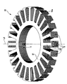
- FIG. 2 is a perspective view showing the stator core of the present embodiment.
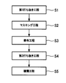
- FIG. 3 is a flowchart showing the procedure of the stator core manufacturing method of the present embodiment.
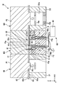
- FIG. 4 is a cross-sectional view illustrating a part of the procedure of the stator core manufacturing method of the present embodiment.
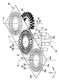
- FIG. 5 is a diagram showing a part of the procedure of the stator core manufacturing method of the present embodiment, and is a perspective view seen from above.
- FIG. 6 is a view showing a part of the procedure of the stator core manufacturing method of the present embodiment, and is a perspective view seen from below.
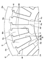
- FIG. 7 is a bottom view of the masking member portion of the present embodiment as viewed from below.
- the motor 1 of the present embodiment is, for example, an outer rotor type motor.
- the motor 1 includes a support member 40, a rotor 30 having a shaft 31 centered on a central axis J1, and a stator 20.
- a direction parallel to the direction in which the central axis J1 extends may be referred to as “vertical direction”.
- the vertical direction is simply a name used for explanation, and does not limit the actual positional relationship and direction of the motor 1.
- the radial direction around the central axis J1 may be simply referred to as “radial direction”
- the circumferential direction around the central axis J1 may be simply referred to as “circumferential direction”.
- the support member 40 has a cylindrical shape extending in the vertical direction about the central axis J1.
- the rotor 30 includes a shaft 31, a magnet holding part 32, and a magnet 33.
- the shaft 31 is rotatably supported with respect to the support member 40 via a bearing fixed to the inner peripheral surface of the support member 40.
- the magnet holding portion 32 has a cylindrical shape that opens downward, and is fixed to the upper end of the shaft 31.
- the magnet 33 is fixed to the radially inner side surface of the magnet holding portion 32.
- the rotor 30 faces the stator 20 via a gap. In FIG. 1, the magnet 33 opposes the stator core 10 mentioned later in a radial direction via a clearance gap.
- the magnet 33 is disposed on the radially outer side than the stator core 10.
- the stator 20 includes a stator core 10, an insulator 21 attached to the stator core 10, and a coil 22 wound around a tooth 12 to be described later via the insulator 21.
- the stator core 10 has an annular shape centering on a central axis J1 extending in the vertical direction.
- the stator core 10 is fixed to the outer peripheral surface of the support member 40.
- the stator core 10 includes a core back 11 and a plurality of teeth 12.
- the core back 11 has an annular shape centered on the central axis J1.
- the teeth 12 extend from the core back 11 in the radial direction. In FIG. 2, the teeth 12 extend radially outward from the core back 11.
- the plurality of teeth 12 are arranged at equal intervals along the circumferential direction.
- the stator core 10 is configured by laminating a plurality of plate members 10a.
- the plate member 10a has a plate shape that expands in the radial direction.
- the laminated plate members 10a are bonded to each other with an adhesive.
- the plate member 10 a includes a core back plate portion 81 and a teeth plate portion 82.
- the core back plate portion 81 has an annular plate shape centered on the central axis J1.
- the core back 11 is configured by stacking the core back plate portions 81 of the plurality of plate members 10a in the vertical direction. That is, the core back plate portion 81 constitutes a part of the core back 11.
- the teeth plate portion 82 extends from the core back plate portion 81 in the radial direction. In FIG. 2, the tooth plate portion 82 extends radially outward from the core back plate portion 81.
- the teeth 12 are configured by stacking the tooth plate portions 82 of the plurality of plate members 10a in the vertical direction. That is, the tooth plate portion 82 constitutes a part of the tooth 12.
- the method for manufacturing the stator core 10 of the present embodiment includes a first punching step S1, a masking step S2, a coating step S3, a second punching step S4, and a stacking step S5.
- each process is performed by the manufacturing apparatus M shown in FIG.
- the manufacturing apparatus M performs each process while conveying the strip-shaped electromagnetic steel sheet 80.
- the electromagnetic steel plate 80 is a magnetic material.
- the Z-axis direction is a direction parallel to the vertical direction.
- the X-axis direction is one direction orthogonal to the Z-axis direction, and is the left-right direction in FIG.
- the Y-axis direction is a direction orthogonal to the Z-axis direction and the X-axis direction.
- the electromagnetic steel sheet 80 is conveyed by the manufacturing apparatus M in a direction parallel to the X-axis direction.
- the direction in which the electromagnetic steel sheet 80 is conveyed may be simply referred to as “conveying direction”.
- the conveyance direction is the longitudinal direction of the strip-shaped electromagnetic steel sheet 80.
- the Y-axis direction is a direction parallel to the short direction of the electromagnetic steel sheet 80 to be conveyed.
- the manufacturing apparatus M includes a first punching device M1, a coating device M2, and a second punching device M3 in order from the upstream side to the downstream side.
- First punching step S1 is a step of punching and removing a part of the electromagnetic steel sheet 80 to form a core plate part 83 having a part of the outer shape of the plate member 10a.
- the core plate portion 83 includes a core back plate portion 81 and a plurality of teeth plate portions 82.
- the first punching step S1 is performed using a first punching device M1 shown in FIG.
- the first punching device M1 includes a first die D1 and a first punch P1 disposed on the upper side of the first die D1.
- a part of the electromagnetic steel sheet 80 is punched out by the first die D1 and the first punch P1, and the first hole 81a and the plurality of second holes 82a shown in FIG. 5 are formed. That is, the first hole 81a and the second hole 82a are holes formed by removing a part of the electromagnetic steel sheet 80 in the first punching step S1.
- the first hole 81a and the second hole 82a penetrate the electromagnetic steel sheet 80 in the vertical direction.
- the first hole 81a has a circular shape.
- the plurality of second hole portions 82a surround the first hole portion 81a at a position away from the first hole portion 81a radially outward.
- the plurality of second hole portions 82a are arranged at equal intervals along the circumferential direction.
- the core plate portion 83 is formed by forming the first hole portion 81a and the second hole portion 82a.
- the core back plate portion 81 is formed between the first hole portion 81a and the second hole portion 82a in the radial direction.
- the teeth plate portion 82 is formed between the circumferential directions of the second hole portions 82a adjacent to each other in the circumferential direction.
- the electromagnetic steel sheet 80 is sent downstream along the transport direction. More specifically, after the first punching step S1 is completed, the portion of the electromagnetic steel sheet 80 that has been subjected to the first punching step S1, that is, the core plate portion 83 is adjacent to the downstream side of the first punching device M1. It is conveyed to the arranged coating apparatus M2.
- the masking step S2 is a step of masking a part of the first surface 80a which is the surface on one side in the vertical direction of the electromagnetic steel sheet 80.
- the first surface 80 a is the lower surface of the electromagnetic steel sheet 80. That is, the first surface 80a is a lower surface of the magnetic material.
- Masking process S2 is performed using coating device M2.
- the coating device M2 includes an upper fixing member F1, a lower fixing member F2 disposed below the upper fixing member F1, and a masking member 50.
- FIG. 4 shows a state in which the electromagnetic steel plate 80 is fixed by the upper fixing member F1 and the lower fixing member F2.
- the upper fixing member F1 contacts the second surface 80b that is the upper surface of the electromagnetic steel plate 80 from above.
- the lower fixing member F2 contacts the first surface 80a from the lower side.
- the upper fixing member F1 has an air vent hole F1a penetrating the upper fixing member F1 in the vertical direction.
- the masking member 50 masks a part of the first surface 80a in the masking step S2. More specifically, the masking member 50 masks a part of the first surface 80a when the electromagnetic steel plate 80 is fixed by the upper fixing member F1 and the lower fixing member F2.
- the masking member 50 is provided on the lower fixing member F2. More specifically, the masking member 50 is disposed inside a recessed portion F2a that is recessed on the lower side provided on the upper surface of the lower fixing member F2.
- the masking member 50 includes a mask part 51, a guide part 52, a wall part 53, an inner cylinder part 54, and a plurality of partition parts 55. 8.
- the spraying portion that sprays the adhesive is disposed inside the wall portion.
- the first surface 80a is masked by the mask portion 51. Therefore, a portion where the adhesive is not applied is formed on the first surface 80a.
- the mask portion 51 has a disk shape that expands in the radial direction. As shown in FIG. 4, the mask part 51 is in contact with the first surface 80a.
- the upper surface of the mask portion 51 is disposed on the same surface as the upper surface of the lower fixing member F2 and orthogonal to the vertical direction.
- the mask portion 51 has a plurality of mask through holes 56 along the circumferential direction. The mask through hole 56 penetrates the mask portion 51 in the vertical direction. In FIG. 6, eight mask through holes 56 are provided. As shown in FIG. 7, the mask through hole 56 has a first mask through part 56a and a second mask through part 56b.
- the first mask penetrating portion 56a extends in the circumferential direction.
- the first mask penetrating portion 56a overlaps the core back plate portion 81 in the vertical direction.
- the dimension in the radial direction of the first mask penetration part 56 a is smaller than the dimension in the radial direction of the core back plate part 81.
- the radially outer portion of the inner edge of the first mask penetrating portion 56 a is disposed on the radially inner side of the radially outer edge of the core back plate portion 81.
- the radially inner portion of the inner edge of the first mask penetrating portion 56 a is disposed on the radially outer side than the radially inner edge of the core back plate portion 81.
- the second mask penetrating portion 56b extends radially outward from the first mask penetrating portion 56a.
- three second mask through portions 56 b are provided for each mask through hole 56.
- the second mask penetrating portion 56b extends radially outward from the circumferential center of the first mask penetrating portion 56a and both circumferential ends of the first mask penetrating portion 56a.
- the second mask penetrating portion 56b overlaps with the tooth plate portion 82 in the vertical direction.
- the circumferential dimension of the second mask penetrating portion 56b is smaller than the circumferential dimension of the tooth plate portion 82.
- the portions on both sides in the circumferential direction are arranged on the inner side of the circumferential edges of the tooth plate portion 82.
- the radially outer portion of the inner edge of the second mask penetrating portion 56 b is disposed radially inward from the radially outer end of the tooth plate portion 82.
- the portion of the first surface 80 a that overlaps with the mask through hole 56 in the vertical direction is exposed to the space S described later through the mask through hole 56.
- the mask part 51 has a disk part 51a, an annular part 51b, a plurality of extending parts 51c, and a plurality of connecting parts 51d.
- the disc portion 51a, the annular portion 51b, the plurality of extending portions 51c, and the plurality of connecting portions 51d are provided by providing the mask through holes 56.
- the disc part 51 a has a disc shape located at the center of the mask part 51.
- the disc part 51 a masks the radially inner edge part of the core back plate part 81.
- the radially outer edge of the disc portion 51 a is disposed on the radially outer side than the radially inner edge of the core back plate portion 81.
- the radially outer edge portion of the disc portion 51 a contacts the radially inner edge portion of the core back plate portion 81 from below.
- the annular portion 51 b is an annular shape located on the outer edge in the radial direction of the mask portion 51.
- the annular portion 51 b masks the radially outer end of the tooth plate portion 82.
- the annular portion 51 b is in contact with the first surface 80 a on the outer side in the radial direction than the core plate portion 83.
- the annular portion 51b surrounds the core plate portion 83 on the first surface 80a.
- the mask part 51 surrounds the core board part 83 in the 1st surface 80a. That is, the mask part 51 contacts the first surface 80a and surrounds the core plate part 83 on the first surface 80a.
- the extending portion 51c extends radially inward from the radially inner edge of the annular portion 51b.
- the extending portion 51c prevents the adhesive from protruding from the tooth plate portion 82 and adheres to the mold.
- the extending portion 51c is disposed between the circumferential directions of the second mask penetrating portions 56b adjacent in the circumferential direction.
- the plurality of extending portions 51c are arranged at equal intervals along the circumferential direction.
- the outer shape of the extending part 51c is a shape along the inner edge of the second hole part 82a.
- An edge portion on one side in the circumferential direction of the extending portion 51c comes into contact with an edge portion on the other side in the circumferential direction of the tooth plate portion 82 adjacent to one side in the circumferential direction of the extending portion 51c from below.
- the edge portion on the other circumferential side of the extending portion 51c comes into contact with the edge portion on the one circumferential side of the tooth plate portion 82 adjacent to the other circumferential side of the extending portion 51c from below.
- the radially inner edge portion of the extending portion 51 c comes into contact with the radially outer edge portion of the core back plate portion 81 from below.
- the connecting part 51d connects the radial outer edge of the disk part 51a and the radial inner edge of the extending part 51c. Therefore, the mask part 51 can be formed with one member by the structure in which the mask part 51 has the connection part 51d.
- the plurality of connecting portions 51d are arranged at equal intervals along the circumferential direction.
- the number of connecting portions 51d is smaller than the number of extending portions 51c. That is, the extending part 51c connected to the disk part 51a by the connecting part 51d is a part of the plurality of extending parts 51c.
- the connecting portion 51d is disposed between the circumferential directions of the first mask penetrating portions 56a adjacent in the circumferential direction.
- the connecting portion 51d contacts the core back plate portion 81 from below. Note that the connecting portion 51d is preferably located between the plurality of nozzles 60a described later in the circumferential direction.
- the guide part 52 positions the mask part 51 in the circumferential direction and the radial direction with respect to the electromagnetic steel sheet 80. As shown in FIGS. 4 and 5, the guide portion 52 is inserted into the first hole portion 81 a and the plurality of second hole portions 82 a formed by punching a part of the electromagnetic steel sheet 80. That is, the guide part 52 is inserted into the hole part 81a formed by removing a part of the magnetic material in step S1.
- the guide part 52 is connected to the mask part 51. More specifically, the guide part 52 protrudes upward from the upper surface of the mask part 51. With this configuration, the mask unit 51 contacts the first surface 80a with high positional accuracy. Therefore, masking of the mask part 51 can be performed suitably. Note that the guide portion 52 may protrude above the upper surface of the electromagnetic steel plate 80.
- the guide part 52 has a first guide part 52a and a plurality of second guide parts 52b.
- the first guide portion 52a protrudes upward from the upper surface of the disc portion 51a.
- the 1st guide part 52a is disk shape.
- the outer diameter of the first guide portion 52a is smaller than the outer diameter of the disc portion 51a and is substantially the same as the inner diameter of the first hole portion 81a.
- the first guide portion 52a is inserted into the first hole portion 81a from below.
- the second guide portion 52b protrudes upward from the upper surface of the extending portion 51c.
- the shape and size of the second guide portion 52b viewed from above are substantially the same as the shape and size of the second hole portion 82a.
- the plurality of second guide portions 52b are respectively inserted into the second hole portions 82a from below.
- the mask part 51 and the guide part 52 may be a part of a single member, or may be separate members.
- the wall portion 53 has a cylindrical shape extending in the vertical direction from the outer edge of the mask portion 51. As shown in FIG. 4, the wall part 53 is arrange
- the partition part 55 connects the inner peripheral surface of the wall part 53 and the outer peripheral surface of the inner cylinder part 54. As shown in FIG. The partition part 55 extends in the radial direction. The some partition part 55 is arrange
- the disc portion 51a, the extending portion 51c, and the connecting portion 51d mask the portion of the lower surface of the core plate portion 83 that does not overlap the mask through hole 56 in the vertical direction.
- the annular portion 51b masks an annular portion surrounding the core plate portion 83 in the first surface 80a.
- the masking portion includes at least a part of the edge portion of the core plate portion 83.
- the masking portion includes the entire edge portion of the core plate portion 83. That is, in the masking step S ⁇ b> 2, the portion to be masked includes the edge at the radially outer end of the core plate portion 83.
- the stator core 10 of the present embodiment is a stator core of the outer rotor type motor 1
- the radial outer end of the core plate portion 83 is the radial outer end of the teeth plate portion 82. That is, in the masking step S ⁇ b> 2, the portion to be masked includes the edge at the radially outer end of the tooth plate portion 82.
- Application step S3 is a step of spraying an adhesive onto the first surface 80a using an electrostatic application method.
- the adhesive is sprayed onto the first surface 80 a in a state where the first surface 80 a is masked by the masking member 50.
- the sprayed adhesive is a liquid adhesive.
- the adhesive is a powder adhesive
- unevenness in the film thickness of the applied adhesive increases due to variations in the particle size of the powder, and it may be difficult to reduce the film thickness.
- the thickness unevenness of the applied adhesive can be reduced, and the thickness of the adhesive can be easily reduced.
- liquid adhesives examples include epoxy adhesives, acrylic adhesives, urethane adhesives, phenolic adhesives, nylon adhesives, polyester adhesives, polyurethane adhesives, modified olefin resin adhesives, Synthetic rubber adhesives, vinyl chloride adhesives, and adhesives combining these adhesives.
- the liquid adhesive may be an anaerobic adhesive, a photocurable adhesive, or a thermosetting adhesive.
- the coating apparatus M ⁇ b> 2 further includes an electrostatic applicator 60.
- the electrostatic applicator 60 includes a nozzle 60a, a ring 62 disposed on the upper side of the nozzle 60a and grounded, and a power source 63 that applies a high voltage to the nozzle 60a.
- the nozzle 60a has a cylindrical shape extending in the vertical direction.
- the outer diameter and inner diameter of the upper part of the nozzle 60a become smaller toward the upper side.
- the nozzle 60a is disposed in a through hole F2b provided in the lower fixing member F2.
- the through hole F2b penetrates from the bottom surface of the recess F2a to the lower surface of the lower fixing member F2. 5 and 6, eight nozzles 60a are provided.
- the nozzle 60a has a spraying portion 61 for spraying an adhesive.
- the spray part 61 is an upper end part of the nozzle 60a.
- the spray part 61 protrudes into the recessed part F2a through the through hole F2b.
- the spray part 61 is disposed inside the wall part 53. Therefore, it is possible to suppress the adhesive sprayed from the spraying part 61 from being scattered outside the masking member 50.
- the spraying part 61 of each nozzle 60a is arranged in each space S. With this configuration, it is possible to prevent the adhesive sprayed from the plurality of nozzles 60a from being applied in the same range.
- the adhesive ejected from the spraying part 61 is in a charged state.
- the charged adhesive becomes fine particles by the repulsive force due to the electrostatic force, passes through the ring 62, and adheres to the first surface 80a. In this manner, the adhesive can be applied to the first surface 80a using the electrostatic coating method.
- the adhesive is ejected upward from the spraying portion 61.
- adhesive agent is sprayed on the 1st surface 80a from lower side in application process S3. Therefore, when the adhesive is a liquid adhesive, the adhesive can be prevented from dripping from the nozzle 60a to the first surface 80a by its own weight when the adhesive is not applied.
- the portion of the first surface 80a to which the adhesive is applied is a portion that is radially unmasked with respect to the mask portion 51, that is, a portion that is not masked by the mask portion 51, that is, a mask through-hole in the first surface 80a.
- This is a portion exposed to the space S through 56.
- a portion of the first surface 80 a exposed to the space S through the mask through hole 56 includes a part of the core back plate part 81 and a part of the teeth plate part 82. That is, in the coating step S ⁇ b> 3, the portion to which the adhesive is applied includes at least a part of the tooth plate portion 82.
- an adhesive is applied to the core back plate portion 81 excluding the radially inner edge portion, the radially outer edge portion, and the portion overlapping the connecting portion 51d in the vertical direction. Further, an adhesive is applied to a portion of the tooth plate portion 82 excluding the edge portion.
- the electromagnetic steel sheet 80 is sent downstream along the transport direction. More specifically, after the coating step S3 is completed, the portion of the electromagnetic steel sheet 80 that has been subjected to the coating step S3, that is, the core plate portion 83 is a second punching disposed adjacent to the downstream side of the coating device M2. It is conveyed to the apparatus M3.
- the second punching step S4 is a step of punching the core plate portion 83 from the electromagnetic steel plate 80 to form the plate member 10a.
- the second punching step S4 is performed using a second punching device M3 shown in FIG.
- the second punching device M3 includes a second die D2 and a second punch P2 disposed on the upper side of the second die D2.
- the core plate 83 is punched out by the second die D2 and the second punch P2, and the punched portion becomes the plate member 10a.
- the lamination step S5 is a step of adhering the plate members 10a to each other via an adhesive and laminating the plate members 10a.
- the plate member 10a formed in the second punching step S4 falls along the guide through hole D2a provided in the second die D2, and is sequentially laminated. Since the adhesive is applied to the lower surface of the plate member 10a in the application step S3, the lower surface of the plate member 10a is bonded to the upper surface of the already laminated plate member 10a with the adhesive.
- the guide through hole D2a penetrates the second die D2 in the vertical direction.
- the radially inner side surface of the guide through hole D2a supports at least a part of the radially outer edge of the plate member 10a.
- the stator core 10 is manufactured by repeating the steps described above and laminating a predetermined number of plate members 10a.
- the first punch P1, the upper fixing member F1, and the second punch P2 all move in the vertical direction.
- the first punch P1, the upper fixing member F1, and the second punch P2 perform a process performed by each apparatus in a state of being positioned at the lowermost side, that is, in a state shown in FIG. In other words, at three locations in the conveying direction of the electromagnetic steel sheet 80, processes corresponding to the apparatus in which each location is located are performed almost simultaneously.
- the electromagnetic steel sheet 80 is sent from the upstream side to the downstream side along the transport direction. .
- the application step S3 is omitted for the plate member 10a positioned on the lowermost side among the plate members 10a constituting the stator core 10. .
- the adhesive since the first surface 80a is masked by the masking step S2, it is possible to prevent the adhesive from being applied to the portion where the adhesive should not be applied on the first surface 80a in the coating step S3. Thereby, it can prevent that an adhesive agent is apply
- the adhesive protrudes from the portion of the stator core 10 facing the rotor 30, the cured adhesive when the rotor 30 rotates may rub against the rotor 30, and the rotational performance of the motor 1 may deteriorate.
- the protruding adhesive is not completely cured when the motor 1 is assembled, the rotor 30 and the stator core 10 may be bonded to each other by the protruding adhesive.
- it can suppress that an adhesive protrudes, it can suppress that the rotational performance of the motor 1 falls, and the rotor 30 and the stator core 10 adhere
- the adhesive can be applied with higher accuracy than when the adhesive is applied by a contact coating method or the like.
- coated adhesive agent can be made thin suitably. Therefore, when the plate member 10a is laminated, it is possible to suppress the adhesive from spreading between the plate members 10a.
- the adhesive when the adhesive is spread between the plate members to bond the plate members, it is difficult to control the spread of the adhesive, and the adhesive protrudes from the plate members, or the adhesive between the plate members May become insufficient.
- the adhesion between the plate members is insufficient, a gap is generated between the stacked plate members, and the magnetic characteristics of the stator core may be deteriorated.
- the adhesive can be prevented from spreading between the plate members 10a, the entire portion where the plate members 10a are bonded together while suppressing the adhesive from spreading and protruding.
- the plate members 10a can be sufficiently bonded to each other. Therefore, it can suppress that the magnetic characteristic of the stator core 10 falls, and the stator core 10 excellent in the magnetic characteristic is obtained. Further, it is easy to apply the adhesive as much as necessary to bond the plate member 10a, and the amount of adhesive used can be reduced.
- this embodiment described above is particularly useful when manufacturing a small stator core.
- a method of fixing the plate members a method of caulking the plate members or a method of welding can be considered.
- these methods there is a problem that residual stress is generated in the plate member and the material characteristics are deteriorated. This problem is particularly remarkable when the plate member is thin.
- the thinner the plate member is the more the eddy current can be prevented from being generated in the stator core. Therefore, the plate member is preferably thinner from the viewpoint of increasing the efficiency of the motor. Therefore, by bonding the plate members 10a to each other using an adhesive as in the present embodiment, the plate member 10a is thinned to increase the efficiency of the motor 1, and the plate member 10a has no residual stress and has material characteristics. Deterioration can be suppressed.
- the edge of the core plate portion 83 is masked in the masking step S2. Therefore, the adhesive is not applied to at least a part of the edge of the core plate portion 83, and the adhesive can be further prevented from protruding from the edge of the core plate 83.
- the entire edge portion of the core plate portion 83 is masked, it is possible to further suppress the adhesive from protruding from the edge portion of the core plate portion 83.
- the masking step S2 only a part of the edge portion of the core plate portion 83 may be masked.
- the edge of the radially outer end of the core plate portion 83 is masked in the masking step S2.
- the edge of the radially outer end of the core plate portion 83 is masked in the masking step S2.
- the present invention is not limited to the above-described embodiment, and other configurations can be adopted.
- the adhesive may be applied only to the teeth plate portion 82 without applying the adhesive to the core back plate portion 81. In this case, the amount of adhesive used can be reduced. Further, since the core back 11 has a smaller influence on the generation of the magnetic circuit of the stator core 10 than the teeth 12, even if a gap is generated between the core back plate portions 81, the magnetic characteristics of the stator core 10 are deteriorated. Hateful. In this case, in the masking step S2, the entire core back plate portion 81 is masked.
- the portion to which the adhesive is applied may be appropriately determined according to the location having a great influence on the magnetic circuit of the stator core 10 and the location where the stator core 10 needs rigidity. Thereby, the usage-amount of an adhesive agent can be reduced, suppressing the magnetic characteristic of the stator core 10 falling.
- an adhesive may be sprayed from the upper side of the electromagnetic steel sheet 80. That is, the first surface on which the adhesive is sprayed may be the upper surface of the electromagnetic steel sheet 80. In this case, since the adhesive is applied to the upper surface of the laminated plate member 10a, the application step S3 is omitted for the plate member 10a positioned on the uppermost side among the plate members 10a constituting the stator core 10.
- the masking step S2 and the coating step S3 may be performed before the first punching step S1.
- the adhesive may be an adhesive other than a liquid adhesive such as a powder adhesive.
- a powder adhesive is about the kind of powder adhesive, it can select similarly to the kind of liquid adhesive mentioned above.
- the configuration of the masking member 50 is not particularly limited as long as a desired position on the first surface 80a can be masked.
- the configuration of the electrostatic applicator 60 is not particularly limited as long as an adhesive can be applied to the first surface 80a by an electrostatic application method.
- the stator core manufacturing method of the present invention can be applied to a stator core of an inner rotor type motor.
- the radially inner end of the plate member is the tip of the teeth plate portion that faces the rotor. Therefore, in the masking process, by masking the edge of the inner end in the radial direction of the core plate part, it is possible to suppress the adhesive from protruding to the inner side in the radial direction of the plate member, and to suppress the protruding adhesive from rubbing against the rotor. it can.
- stator core manufacturing method of the present invention has been described on the assumption that the core back is annular, it is not limited to this configuration. That is, the stator core formed by being stacked after the above-described stacking step may not have an annular core back.
- the stator core manufacturing method of the present invention may be applied to the manufacture of a split core and a developed core.
- a plurality of split cores in a split state may be manufactured by the same process as that of the above-described embodiment.
- the stator core manufacturing method includes a stator core having an annular core back by assembling a plurality of divided cores manufactured in a divided state, in addition to the same steps as in the above-described embodiment. May be included.
- the method for manufacturing a stator core of the present invention when the method for manufacturing a stator core of the present invention is applied to a deployment core, the deployment core in a deployed state may be manufactured by the same process as in the above-described embodiment.
- the method for manufacturing a stator core according to one aspect of the present invention includes a step of forming a stator core having an annular core back by rounding the expanded core in the expanded state, in addition to the steps similar to the above-described embodiment. May be included.
- a method for manufacturing a stator core according to the present invention has been described with respect to a process of punching out an electromagnetic steel sheet and forming a plate member, but is not limited thereto.
- an amorphous material may be punched out to form a plate member, or an amorphous material formed in a predetermined shape may be used.
- a method for manufacturing a stator core according to one aspect of the present invention includes a step of punching a magnetic material such as an electromagnetic steel plate or an amorphous material, a step of masking the punched magnetic material, and spraying an adhesive.
- a manufacturing method may be used.
- SYMBOLS 10 ... Stator core, 10a ... Plate member, 20 ... Stator, 50 ... Masking member, 51 ... Mask part, 52 ... Guide part, 53 ... Wall part, 61 ... Spraying part, 80 ... Electromagnetic steel plate (magnetic material), 80a ... 1st surface, 83 ... Core plate part, J1 ... Central axis, S1 ... 1st punching process (process S1), S2 ... Masking process (process S2), S3 ... Application
Landscapes
- Engineering & Computer Science (AREA)
- Power Engineering (AREA)
- Manufacturing & Machinery (AREA)
- Manufacture Of Motors, Generators (AREA)
- Iron Core Of Rotating Electric Machines (AREA)
Abstract
Un procédé de fabrication de noyau de stator selon un mode de réalisation de la présente invention est un procédé de fabrication d'un noyau de stator configuré par stratification d'éléments de plaque multiples centrés autour d'un axe central s'étendant dans la direction verticale, ledit procédé comprenant : une étape S1 dans laquelle une partie d'un matériau magnétique est retirée par poinçonnage pour former des parties de plaque de noyau possédant une partie de la forme externe d'un élément de plaque ; une étape S2 dans laquelle une partie d'une première surface, qui est une surface du matériau magnétique dans la direction verticale, est masquée ; une étape S3 dans laquelle un agent adhésif est pulvérisé sur la première surface au moyen d'un procédé de revêtement électrostatique ; une étape S4 dans laquelle les parties de plaque de noyau sont poinçonnées à partir du matériau magnétique pour former des éléments de plaque ; et une étape S5 dans laquelle les éléments de plaque sont mutuellement collés au moyen de l'agent adhésif pour stratifier les éléments de plaque.
Priority Applications (2)
| Application Number | Priority Date | Filing Date | Title |
|---|---|---|---|
| JP2018518104A JP6908035B2 (ja) | 2016-05-20 | 2017-02-28 | ステータコアの製造方法 |
| CN201780029502.9A CN109155574B (zh) | 2016-05-20 | 2017-02-28 | 定子铁芯的制造方法 |
Applications Claiming Priority (2)
| Application Number | Priority Date | Filing Date | Title |
|---|---|---|---|
| JP2016-101418 | 2016-05-20 | ||
| JP2016101418 | 2016-05-20 |
Publications (1)
| Publication Number | Publication Date |
|---|---|
| WO2017199527A1 true WO2017199527A1 (fr) | 2017-11-23 |
Family
ID=60326383
Family Applications (1)
| Application Number | Title | Priority Date | Filing Date |
|---|---|---|---|
| PCT/JP2017/007802 Ceased WO2017199527A1 (fr) | 2016-05-20 | 2017-02-28 | Procédé de fabrication de noyau de stator |
Country Status (3)
| Country | Link |
|---|---|
| JP (1) | JP6908035B2 (fr) |
| CN (1) | CN109155574B (fr) |
| WO (1) | WO2017199527A1 (fr) |
Cited By (21)
| Publication number | Priority date | Publication date | Assignee | Title |
|---|---|---|---|---|
| JP2019193561A (ja) * | 2018-04-23 | 2019-10-31 | キーンレ ウント シュピース ゲーエムベーハー | 積層コアを製造する方法及び当該方法を実行するために接着剤を塗布する装置 |
| JPWO2020129938A1 (ja) * | 2018-12-17 | 2021-02-15 | 日本製鉄株式会社 | 積層コア、コアブロック、回転電機およびコアブロックの製造方法 |
| JP2021027596A (ja) * | 2019-07-31 | 2021-02-22 | トヨタ紡織株式会社 | 積層鉄心の製造方法及び製造装置 |
| JP2022001014A (ja) * | 2020-06-17 | 2022-01-04 | 日本製鉄株式会社 | 積層コアおよび積層コアの製造方法 |
| JP2023101882A (ja) * | 2022-01-11 | 2023-07-24 | 三菱電機株式会社 | 積層鉄心の製造装置、積層鉄心の製造方法および電気機械 |
| US11710990B2 (en) | 2018-12-17 | 2023-07-25 | Nippon Steel Corporation | Laminated core with circumferentially spaced adhesion parts on teeth |
| US11742129B2 (en) | 2018-12-17 | 2023-08-29 | Nippon Steel Corporation | Adhesively-laminated core, manufacturing method thereof, and electric motor |
| US11855485B2 (en) | 2018-12-17 | 2023-12-26 | Nippon Steel Corporation | Laminated core, method of manufacturing same, and electric motor |
| US11863017B2 (en) | 2018-12-17 | 2024-01-02 | Nippon Steel Corporation | Laminated core and electric motor |
| US11915860B2 (en) | 2018-12-17 | 2024-02-27 | Nippon Steel Corporation | Laminated core and electric motor |
| US11923130B2 (en) | 2018-12-17 | 2024-03-05 | Nippon Steel Corporation | Laminated core and electric motor |
| US11973369B2 (en) | 2018-12-17 | 2024-04-30 | Nippon Steel Corporation | Laminated core with center electrical steel sheets adhered with adhesive and some electrical steel sheets fixed to each other on both ends of the center sheets |
| US11979059B2 (en) | 2018-12-17 | 2024-05-07 | Nippon Steel Corporation | Laminated core and electric motor |
| US11990795B2 (en) | 2018-12-17 | 2024-05-21 | Nippon Steel Corporation | Adhesively-laminated core for stator, method of manufacturing same, and electric motor |
| US11996231B2 (en) | 2018-12-17 | 2024-05-28 | Nippon Steel Corporation | Laminated core and electric motor |
| US12074476B2 (en) | 2018-12-17 | 2024-08-27 | Nippon Steel Corporation | Adhesively-laminated core for stator and electric motor |
| US12081068B2 (en) | 2018-12-17 | 2024-09-03 | Nippon Steel Corporation | Laminated core with some electrical steel sheets adhered with adhesive and some electrical steel sheets fixed to each other |
| US12104096B2 (en) | 2018-12-17 | 2024-10-01 | Nippon Steel Corporation | Laminated core, laminated core manufacturing method, and electric motor |
| US12154711B2 (en) | 2018-12-17 | 2024-11-26 | Nippon Steel Corporation | Adhesively-laminated core for stator and electric motor |
| US12261482B2 (en) | 2018-12-17 | 2025-03-25 | Nippon Steel Corporation | Laminated core and electric motor |
| US12266971B2 (en) | 2018-12-17 | 2025-04-01 | Nippon Steel Corporation | Adhesively-laminated core for stator, method of manufacturing the same, and electric motor |
Families Citing this family (4)
| Publication number | Priority date | Publication date | Assignee | Title |
|---|---|---|---|---|
| JP2020150627A (ja) * | 2019-03-12 | 2020-09-17 | 日本電産株式会社 | 積層鉄心、ステータおよびロータ |
| JP7222328B2 (ja) * | 2019-07-17 | 2023-02-15 | 日本製鉄株式会社 | 積層コアおよび回転電機 |
| TWI709290B (zh) | 2019-09-26 | 2020-11-01 | 盟鑫金屬股份有限公司 | 電動車馬達之磁芯的製造方法 |
| EP4325534B1 (fr) * | 2021-04-14 | 2025-06-04 | Nippon Steel Corporation | Procédé de fabrication de noyau stratifié lié et dispositif de fabrication de noyau stratifié lié |
Citations (4)
| Publication number | Priority date | Publication date | Assignee | Title |
|---|---|---|---|---|
| JPH07336969A (ja) * | 1994-06-09 | 1995-12-22 | Nkk Corp | 接着鉄心用電磁鋼板およびその製造方法 |
| JPH10314658A (ja) * | 1997-05-22 | 1998-12-02 | Sankyo Seiki Mfg Co Ltd | 粉体塗装方法、および電機子コアの製造方法 |
| JP2005269732A (ja) * | 2004-03-17 | 2005-09-29 | Nippon Steel Corp | 鉄芯の製造方法とその方法に適した装置 |
| JP2011066987A (ja) * | 2009-09-16 | 2011-03-31 | Denso Corp | 積層コアの製造方法、積層コア及び回転電機 |
Family Cites Families (1)
| Publication number | Priority date | Publication date | Assignee | Title |
|---|---|---|---|---|
| JP3725776B2 (ja) * | 2000-11-10 | 2005-12-14 | 新日本製鐵株式会社 | 積層鉄芯の製造方法およびその製造装置 |
-
2017
- 2017-02-28 WO PCT/JP2017/007802 patent/WO2017199527A1/fr not_active Ceased
- 2017-02-28 CN CN201780029502.9A patent/CN109155574B/zh not_active Expired - Fee Related
- 2017-02-28 JP JP2018518104A patent/JP6908035B2/ja not_active Expired - Fee Related
Patent Citations (4)
| Publication number | Priority date | Publication date | Assignee | Title |
|---|---|---|---|---|
| JPH07336969A (ja) * | 1994-06-09 | 1995-12-22 | Nkk Corp | 接着鉄心用電磁鋼板およびその製造方法 |
| JPH10314658A (ja) * | 1997-05-22 | 1998-12-02 | Sankyo Seiki Mfg Co Ltd | 粉体塗装方法、および電機子コアの製造方法 |
| JP2005269732A (ja) * | 2004-03-17 | 2005-09-29 | Nippon Steel Corp | 鉄芯の製造方法とその方法に適した装置 |
| JP2011066987A (ja) * | 2009-09-16 | 2011-03-31 | Denso Corp | 積層コアの製造方法、積層コア及び回転電機 |
Cited By (26)
| Publication number | Priority date | Publication date | Assignee | Title |
|---|---|---|---|---|
| JP7377620B2 (ja) | 2018-04-23 | 2023-11-10 | キーンレ ウント シュピース ゲーエムベーハー | 積層コアを製造する方法及び当該方法を実行するために接着剤を塗布する装置 |
| JP2019193561A (ja) * | 2018-04-23 | 2019-10-31 | キーンレ ウント シュピース ゲーエムベーハー | 積層コアを製造する方法及び当該方法を実行するために接着剤を塗布する装置 |
| US11973369B2 (en) | 2018-12-17 | 2024-04-30 | Nippon Steel Corporation | Laminated core with center electrical steel sheets adhered with adhesive and some electrical steel sheets fixed to each other on both ends of the center sheets |
| US11855485B2 (en) | 2018-12-17 | 2023-12-26 | Nippon Steel Corporation | Laminated core, method of manufacturing same, and electric motor |
| US12266971B2 (en) | 2018-12-17 | 2025-04-01 | Nippon Steel Corporation | Adhesively-laminated core for stator, method of manufacturing the same, and electric motor |
| US11710990B2 (en) | 2018-12-17 | 2023-07-25 | Nippon Steel Corporation | Laminated core with circumferentially spaced adhesion parts on teeth |
| US11742129B2 (en) | 2018-12-17 | 2023-08-29 | Nippon Steel Corporation | Adhesively-laminated core, manufacturing method thereof, and electric motor |
| US12261482B2 (en) | 2018-12-17 | 2025-03-25 | Nippon Steel Corporation | Laminated core and electric motor |
| US11979059B2 (en) | 2018-12-17 | 2024-05-07 | Nippon Steel Corporation | Laminated core and electric motor |
| US11863017B2 (en) | 2018-12-17 | 2024-01-02 | Nippon Steel Corporation | Laminated core and electric motor |
| US11915860B2 (en) | 2018-12-17 | 2024-02-27 | Nippon Steel Corporation | Laminated core and electric motor |
| US11923130B2 (en) | 2018-12-17 | 2024-03-05 | Nippon Steel Corporation | Laminated core and electric motor |
| US12154711B2 (en) | 2018-12-17 | 2024-11-26 | Nippon Steel Corporation | Adhesively-laminated core for stator and electric motor |
| JPWO2020129938A1 (ja) * | 2018-12-17 | 2021-02-15 | 日本製鉄株式会社 | 積層コア、コアブロック、回転電機およびコアブロックの製造方法 |
| US12081068B2 (en) | 2018-12-17 | 2024-09-03 | Nippon Steel Corporation | Laminated core with some electrical steel sheets adhered with adhesive and some electrical steel sheets fixed to each other |
| US11996231B2 (en) | 2018-12-17 | 2024-05-28 | Nippon Steel Corporation | Laminated core and electric motor |
| US12068097B2 (en) | 2018-12-17 | 2024-08-20 | Nippon Steel Corporation | Laminated core, core block, electric motor and method of producing core block |
| US12074476B2 (en) | 2018-12-17 | 2024-08-27 | Nippon Steel Corporation | Adhesively-laminated core for stator and electric motor |
| US11990795B2 (en) | 2018-12-17 | 2024-05-21 | Nippon Steel Corporation | Adhesively-laminated core for stator, method of manufacturing same, and electric motor |
| US12104096B2 (en) | 2018-12-17 | 2024-10-01 | Nippon Steel Corporation | Laminated core, laminated core manufacturing method, and electric motor |
| JP7584888B2 (ja) | 2019-07-31 | 2024-11-18 | トヨタ紡織株式会社 | 積層鉄心の製造方法及び製造装置 |
| JP2021027596A (ja) * | 2019-07-31 | 2021-02-22 | トヨタ紡織株式会社 | 積層鉄心の製造方法及び製造装置 |
| JP2022001014A (ja) * | 2020-06-17 | 2022-01-04 | 日本製鉄株式会社 | 積層コアおよび積層コアの製造方法 |
| JP7833862B2 (ja) | 2020-06-17 | 2026-03-23 | 日本製鉄株式会社 | 積層コアおよび積層コアの製造方法 |
| JP2023101882A (ja) * | 2022-01-11 | 2023-07-24 | 三菱電機株式会社 | 積層鉄心の製造装置、積層鉄心の製造方法および電気機械 |
| JP7858317B2 (ja) | 2022-01-11 | 2026-05-14 | 三菱電機株式会社 | 積層鉄心の製造装置、積層鉄心の製造方法および電気機械 |
Also Published As
| Publication number | Publication date |
|---|---|
| JP6908035B2 (ja) | 2021-07-21 |
| JPWO2017199527A1 (ja) | 2019-06-20 |
| CN109155574B (zh) | 2020-11-06 |
| CN109155574A (zh) | 2019-01-04 |
Similar Documents
| Publication | Publication Date | Title |
|---|---|---|
| JP6908035B2 (ja) | ステータコアの製造方法 | |
| JP6675601B1 (ja) | 積層コアの製造方法、接着剤塗布装置及び積層コアの製造装置 | |
| US10328673B2 (en) | Method of producing laminated steel plate and device for producing the same | |
| CN107302291B (zh) | 旋转电机用转子的制造方法 | |
| CN113169641A (zh) | 层叠铁芯、层叠铁芯的制造方法、以及旋转电机 | |
| JPWO2020129929A1 (ja) | ステータ用接着積層コアおよび回転電機 | |
| JP4938389B2 (ja) | 積層コアおよびステータ | |
| JP2016140134A (ja) | モータコアおよびモータコアの製造方法 | |
| JPWO2018043429A1 (ja) | 積層鉄心、積層鉄心の製造方法、および積層鉄心を用いた電機子 | |
| KR102493101B1 (ko) | 전자 강판, 적층 코어 및 회전 전기 기기 | |
| CN108432102A (zh) | 叠片铁芯的制造方法以及内铁芯和外铁芯 | |
| JP6438731B2 (ja) | 打抜き方法及び打抜き装置並びに積層鉄心の製造方法 | |
| US12126217B2 (en) | Core block, laminated core, and electric motor | |
| EP4430736B1 (fr) | Procédé de production d'un matériau multicouche avant la presse à estamper pour composants stratifiés de moteur électrique | |
| CN110574255A (zh) | 用于将片材件连接为叠片组的设备和方法 | |
| JP6630123B2 (ja) | 積層鉄心及びその製造方法 | |
| KR102066460B1 (ko) | 모터 코어용 접착강판의 제조방법 | |
| JP4752613B2 (ja) | 積層部品の製造方法 | |
| JPWO2018047727A1 (ja) | ロータの製造方法 | |
| US20190115811A1 (en) | Method of manufacturing laminated core | |
| EP3182567B1 (fr) | Procédé et dispositif de collage des cotés latéraux d'un noyeau statorique | |
| JP2016096634A (ja) | 打抜き方法及び打抜き装置並びに積層鉄心の製造方法 | |
| CN108141116B (zh) | 层叠铁芯的制造方法 | |
| JP2023103524A (ja) | モータのステータ | |
| JP2023101882A (ja) | 積層鉄心の製造装置、積層鉄心の製造方法および電気機械 |
Legal Events
| Date | Code | Title | Description |
|---|---|---|---|
| NENP | Non-entry into the national phase |
Ref country code: DE |
|
| 121 | Ep: the epo has been informed by wipo that ep was designated in this application |
Ref document number: 17798964 Country of ref document: EP Kind code of ref document: A1 |
|
| ENP | Entry into the national phase |
Ref document number: 2018518104 Country of ref document: JP Kind code of ref document: A |
|
| 122 | Ep: pct application non-entry in european phase |
Ref document number: 17798964 Country of ref document: EP Kind code of ref document: A1 |