WO2017199574A1 - 内燃機関制御装置 - Google Patents
内燃機関制御装置 Download PDFInfo
- Publication number
- WO2017199574A1 WO2017199574A1 PCT/JP2017/011296 JP2017011296W WO2017199574A1 WO 2017199574 A1 WO2017199574 A1 WO 2017199574A1 JP 2017011296 W JP2017011296 W JP 2017011296W WO 2017199574 A1 WO2017199574 A1 WO 2017199574A1
- Authority
- WO
- WIPO (PCT)
- Prior art keywords
- injection valve
- internal combustion
- combustion engine
- fuel
- fluid
- Prior art date
- Legal status (The legal status is an assumption and is not a legal conclusion. Google has not performed a legal analysis and makes no representation as to the accuracy of the status listed.)
- Ceased
Links
Images








Classifications
-
- F—MECHANICAL ENGINEERING; LIGHTING; HEATING; WEAPONS; BLASTING
- F02—COMBUSTION ENGINES; HOT-GAS OR COMBUSTION-PRODUCT ENGINE PLANTS
- F02B—INTERNAL-COMBUSTION PISTON ENGINES; COMBUSTION ENGINES IN GENERAL
- F02B17/00—Engines characterised by means for effecting stratification of charge in cylinders
- F02B17/005—Engines characterised by means for effecting stratification of charge in cylinders having direct injection in the combustion chamber
-
- F—MECHANICAL ENGINEERING; LIGHTING; HEATING; WEAPONS; BLASTING
- F02—COMBUSTION ENGINES; HOT-GAS OR COMBUSTION-PRODUCT ENGINE PLANTS
- F02B—INTERNAL-COMBUSTION PISTON ENGINES; COMBUSTION ENGINES IN GENERAL
- F02B23/00—Other engines characterised by special shape or construction of combustion chambers to improve operation
- F02B23/08—Other engines characterised by special shape or construction of combustion chambers to improve operation with positive ignition
- F02B23/10—Other engines characterised by special shape or construction of combustion chambers to improve operation with positive ignition with separate admission of air and fuel into cylinder
-
- F—MECHANICAL ENGINEERING; LIGHTING; HEATING; WEAPONS; BLASTING
- F02—COMBUSTION ENGINES; HOT-GAS OR COMBUSTION-PRODUCT ENGINE PLANTS
- F02B—INTERNAL-COMBUSTION PISTON ENGINES; COMBUSTION ENGINES IN GENERAL
- F02B23/00—Other engines characterised by special shape or construction of combustion chambers to improve operation
- F02B23/08—Other engines characterised by special shape or construction of combustion chambers to improve operation with positive ignition
- F02B23/10—Other engines characterised by special shape or construction of combustion chambers to improve operation with positive ignition with separate admission of air and fuel into cylinder
- F02B23/104—Other engines characterised by special shape or construction of combustion chambers to improve operation with positive ignition with separate admission of air and fuel into cylinder the injector being placed on a side position of the cylinder
-
- F—MECHANICAL ENGINEERING; LIGHTING; HEATING; WEAPONS; BLASTING
- F02—COMBUSTION ENGINES; HOT-GAS OR COMBUSTION-PRODUCT ENGINE PLANTS
- F02D—CONTROLLING COMBUSTION ENGINES
- F02D41/00—Electrical control of supply of combustible mixture or its constituents
- F02D41/02—Circuit arrangements for generating control signals
-
- F—MECHANICAL ENGINEERING; LIGHTING; HEATING; WEAPONS; BLASTING
- F02—COMBUSTION ENGINES; HOT-GAS OR COMBUSTION-PRODUCT ENGINE PLANTS
- F02D—CONTROLLING COMBUSTION ENGINES
- F02D41/00—Electrical control of supply of combustible mixture or its constituents
- F02D41/02—Circuit arrangements for generating control signals
- F02D41/04—Introducing corrections for particular operating conditions
-
- F—MECHANICAL ENGINEERING; LIGHTING; HEATING; WEAPONS; BLASTING
- F02—COMBUSTION ENGINES; HOT-GAS OR COMBUSTION-PRODUCT ENGINE PLANTS
- F02D—CONTROLLING COMBUSTION ENGINES
- F02D41/00—Electrical control of supply of combustible mixture or its constituents
- F02D41/30—Controlling fuel injection
- F02D41/3011—Controlling fuel injection according to or using specific or several modes of combustion
- F02D41/3017—Controlling fuel injection according to or using specific or several modes of combustion characterised by the mode(s) being used
- F02D41/3023—Controlling fuel injection according to or using specific or several modes of combustion characterised by the mode(s) being used a mode being the stratified charge spark-ignited mode
-
- F—MECHANICAL ENGINEERING; LIGHTING; HEATING; WEAPONS; BLASTING
- F02—COMBUSTION ENGINES; HOT-GAS OR COMBUSTION-PRODUCT ENGINE PLANTS
- F02D—CONTROLLING COMBUSTION ENGINES
- F02D41/00—Electrical control of supply of combustible mixture or its constituents
- F02D41/30—Controlling fuel injection
- F02D41/3011—Controlling fuel injection according to or using specific or several modes of combustion
- F02D41/3017—Controlling fuel injection according to or using specific or several modes of combustion characterised by the mode(s) being used
- F02D41/3023—Controlling fuel injection according to or using specific or several modes of combustion characterised by the mode(s) being used a mode being the stratified charge spark-ignited mode
- F02D41/3029—Controlling fuel injection according to or using specific or several modes of combustion characterised by the mode(s) being used a mode being the stratified charge spark-ignited mode further comprising a homogeneous charge spark-ignited mode
-
- F—MECHANICAL ENGINEERING; LIGHTING; HEATING; WEAPONS; BLASTING
- F02—COMBUSTION ENGINES; HOT-GAS OR COMBUSTION-PRODUCT ENGINE PLANTS
- F02D—CONTROLLING COMBUSTION ENGINES
- F02D41/00—Electrical control of supply of combustible mixture or its constituents
- F02D41/30—Controlling fuel injection
- F02D41/3094—Controlling fuel injection the fuel injection being effected by at least two different injectors, e.g. one in the intake manifold and one in the cylinder
-
- F—MECHANICAL ENGINEERING; LIGHTING; HEATING; WEAPONS; BLASTING
- F02—COMBUSTION ENGINES; HOT-GAS OR COMBUSTION-PRODUCT ENGINE PLANTS
- F02D—CONTROLLING COMBUSTION ENGINES
- F02D41/00—Electrical control of supply of combustible mixture or its constituents
- F02D41/30—Controlling fuel injection
- F02D41/32—Controlling fuel injection of the low pressure type
- F02D41/34—Controlling fuel injection of the low pressure type with means for controlling injection timing or duration
-
- F—MECHANICAL ENGINEERING; LIGHTING; HEATING; WEAPONS; BLASTING
- F02—COMBUSTION ENGINES; HOT-GAS OR COMBUSTION-PRODUCT ENGINE PLANTS
- F02D—CONTROLLING COMBUSTION ENGINES
- F02D41/00—Electrical control of supply of combustible mixture or its constituents
- F02D41/30—Controlling fuel injection
- F02D41/32—Controlling fuel injection of the low pressure type
- F02D41/34—Controlling fuel injection of the low pressure type with means for controlling injection timing or duration
- F02D41/345—Controlling injection timing
-
- F—MECHANICAL ENGINEERING; LIGHTING; HEATING; WEAPONS; BLASTING
- F02—COMBUSTION ENGINES; HOT-GAS OR COMBUSTION-PRODUCT ENGINE PLANTS
- F02D—CONTROLLING COMBUSTION ENGINES
- F02D41/00—Electrical control of supply of combustible mixture or its constituents
- F02D41/30—Controlling fuel injection
- F02D41/38—Controlling fuel injection of the high pressure type
-
- F—MECHANICAL ENGINEERING; LIGHTING; HEATING; WEAPONS; BLASTING
- F02—COMBUSTION ENGINES; HOT-GAS OR COMBUSTION-PRODUCT ENGINE PLANTS
- F02D—CONTROLLING COMBUSTION ENGINES
- F02D41/00—Electrical control of supply of combustible mixture or its constituents
- F02D41/30—Controlling fuel injection
- F02D41/38—Controlling fuel injection of the high pressure type
- F02D41/40—Controlling fuel injection of the high pressure type with means for controlling injection timing or duration
- F02D41/402—Multiple injections
-
- F—MECHANICAL ENGINEERING; LIGHTING; HEATING; WEAPONS; BLASTING
- F02—COMBUSTION ENGINES; HOT-GAS OR COMBUSTION-PRODUCT ENGINE PLANTS
- F02F—CYLINDERS, PISTONS OR CASINGS, FOR COMBUSTION ENGINES; ARRANGEMENTS OF SEALINGS IN COMBUSTION ENGINES
- F02F1/00—Cylinders; Cylinder heads
- F02F1/24—Cylinder heads
-
- F—MECHANICAL ENGINEERING; LIGHTING; HEATING; WEAPONS; BLASTING
- F02—COMBUSTION ENGINES; HOT-GAS OR COMBUSTION-PRODUCT ENGINE PLANTS
- F02M—SUPPLYING COMBUSTION ENGINES IN GENERAL WITH COMBUSTIBLE MIXTURES OR CONSTITUENTS THEREOF
- F02M51/00—Fuel-injection apparatus characterised by being operated electrically
-
- F—MECHANICAL ENGINEERING; LIGHTING; HEATING; WEAPONS; BLASTING
- F02—COMBUSTION ENGINES; HOT-GAS OR COMBUSTION-PRODUCT ENGINE PLANTS
- F02M—SUPPLYING COMBUSTION ENGINES IN GENERAL WITH COMBUSTIBLE MIXTURES OR CONSTITUENTS THEREOF
- F02M61/00—Fuel-injectors not provided for in groups F02M39/00 - F02M57/00 or F02M67/00
- F02M61/14—Arrangements of injectors with respect to engines; Mounting of injectors
-
- F—MECHANICAL ENGINEERING; LIGHTING; HEATING; WEAPONS; BLASTING
- F02—COMBUSTION ENGINES; HOT-GAS OR COMBUSTION-PRODUCT ENGINE PLANTS
- F02D—CONTROLLING COMBUSTION ENGINES
- F02D41/00—Electrical control of supply of combustible mixture or its constituents
- F02D41/30—Controlling fuel injection
- F02D41/38—Controlling fuel injection of the high pressure type
- F02D2041/389—Controlling fuel injection of the high pressure type for injecting directly into the cylinder
-
- F—MECHANICAL ENGINEERING; LIGHTING; HEATING; WEAPONS; BLASTING
- F02—COMBUSTION ENGINES; HOT-GAS OR COMBUSTION-PRODUCT ENGINE PLANTS
- F02D—CONTROLLING COMBUSTION ENGINES
- F02D2200/00—Input parameters for engine control
- F02D2200/02—Input parameters for engine control the parameters being related to the engine
- F02D2200/10—Parameters related to the engine output, e.g. engine torque or engine speed
- F02D2200/101—Engine speed
-
- Y—GENERAL TAGGING OF NEW TECHNOLOGICAL DEVELOPMENTS; GENERAL TAGGING OF CROSS-SECTIONAL TECHNOLOGIES SPANNING OVER SEVERAL SECTIONS OF THE IPC; TECHNICAL SUBJECTS COVERED BY FORMER USPC CROSS-REFERENCE ART COLLECTIONS [XRACs] AND DIGESTS
- Y02—TECHNOLOGIES OR APPLICATIONS FOR MITIGATION OR ADAPTATION AGAINST CLIMATE CHANGE
- Y02T—CLIMATE CHANGE MITIGATION TECHNOLOGIES RELATED TO TRANSPORTATION
- Y02T10/00—Road transport of goods or passengers
- Y02T10/10—Internal combustion engine [ICE] based vehicles
- Y02T10/12—Improving ICE efficiencies
-
- Y—GENERAL TAGGING OF NEW TECHNOLOGICAL DEVELOPMENTS; GENERAL TAGGING OF CROSS-SECTIONAL TECHNOLOGIES SPANNING OVER SEVERAL SECTIONS OF THE IPC; TECHNICAL SUBJECTS COVERED BY FORMER USPC CROSS-REFERENCE ART COLLECTIONS [XRACs] AND DIGESTS
- Y02—TECHNOLOGIES OR APPLICATIONS FOR MITIGATION OR ADAPTATION AGAINST CLIMATE CHANGE
- Y02T—CLIMATE CHANGE MITIGATION TECHNOLOGIES RELATED TO TRANSPORTATION
- Y02T10/00—Road transport of goods or passengers
- Y02T10/10—Internal combustion engine [ICE] based vehicles
- Y02T10/40—Engine management systems
Definitions
- the present invention relates to an internal combustion engine control apparatus, and more particularly to an apparatus for controlling a fuel injection valve of a spark ignition type internal combustion engine.
- Stratified combustion is a method of reducing pump loss caused by throttle throttling by sucking air into the combustion chamber so that the operating air-fuel ratio becomes larger than the theoretical mixing ratio. It is necessary to stratify an air-fuel mixture with an appropriate equivalent ratio (approximately 1) in the vicinity of the spark plug.
- an object of the present invention is to form a stratified mixture stably around a spark plug.
- the present invention provides an internal combustion engine controller for controlling an internal combustion engine, wherein the internal combustion engine includes a fluid injection valve provided along an axial direction of a spark plug, and the fluid injection valve. And a fuel injection valve provided in a direction crossing the axial direction of the fluid injection valve, and after injecting fluid from the fluid injection valve in the compression stroke, the fuel injection A control unit is provided for controlling the fluid injection valve and the fuel injection valve so as to inject fluid from the valve.
- the structure in the intake pipe cross section of the Example of this invention is shown.
- the structure in the cylinder center cross section of the Example of this invention is shown.
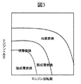
- a combustion mode switching map for engine speed and engine torque is shown.
- the fuel injection with respect to combustion mode and the ignition timing chart are shown.
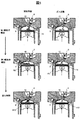
- the fuel behavior and gas flow in the Example of this invention are shown.
- the definition of the crossing angle ⁇ is shown.
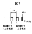
- requirement (DELTA) t is shown.
- a change in the demand ⁇ t with respect to the intersection angle ⁇ is shown.
- In-cylinder air flow when the crossing angle ⁇ is 90 ° is shown.
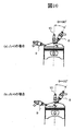
- (A) shows in-cylinder air flow when ⁇ t 0, and
- FIG. 1 shows an outline of the configuration
- FIG. 2 shows a mounting position of the fuel injector in the center section of the cylinder.
- a combustion chamber is formed by the cylinder head 1, the cylinder block 2, and the piston 3 inserted into the cylinder block, and the intake pipe 4 and the exhaust pipe 5 are branched into two for each cylinder and connected to the cylinder.
- Two intake valves 6 and two exhaust valves 7 are provided so as to open and close the opening.
- the intake valve 4 and the exhaust valve 5 have a cam operation method and rotate in conjunction with the crankshaft 16.
- the cam profile is generally used, and the top dead center is set when the exhaust valve closes and when the intake valve begins to open.
- the first fuel injector 8 does not necessarily have to be a fuel injector, and any fluid injection valve that injects fluid may be used. That is, in this embodiment, the internal combustion engine (direct injection engine) includes a fluid injection valve (first fuel injector 8) provided along the axial direction of the spark plug 10 and a fluid injection valve (first fuel).
- a fuel injection valve (second fuel injector 9) is provided separately from the injector 8) and provided in a direction intersecting the axial direction of the fluid injection valve (first fuel injector 8).
- the fluid injection valve (first fuel injector 8) is provided adjacent to the spark plug 10, and the angle formed between the axial direction of the fluid injection valve (first fuel injector 8) and the cylinder central axis direction is 0 °. To 45 °.
- the nozzle tips of the fluid injection valve and the fuel injection valve are inserted into the combustion chamber of the internal combustion engine.
- Fuel is stored in the fuel tank 12 and sent to the high-pressure pump 14 through the fuel pipe by the feed pump 13.
- the high-pressure fuel pump 14 is driven by an exhaust cam, and the pressurized fuel is sent to the common rail 15.
- the feed pump 13 can boost the fuel to about 0.3 MPa and send it to the high-pressure pump 14, and the high-pressure pump 14 can boost the fuel to about 15 MPa and send it to the common rail 15.
- a fuel pressure sensor 16 is installed on the common rail 15 so that the fuel pressure can be detected.
- a total of eight fuel injectors are connected to the tip of the common rail 16 for each cylinder.
- the piston 3 is connected to a crankshaft 18 via a connecting rod 17, and the engine speed can be detected by a crank angle sensor 19.
- a cell motor (not shown) is connected to the crankshaft 18 and can be started by rotating the crankshaft by the cell motor when the engine is started.
- a water temperature sensor 20 is attached to the cylinder block, and the temperature of the engine coolant can be detected.
- a collector 21 is connected upstream of the intake pipe 4.
- an air flow sensor and a throttle valve are provided upstream of the collector, and the amount of air taken into the combustion chamber can be adjusted by opening and closing the throttle. Although only one cylinder is shown in the figure, air is distributed from the collector to each cylinder.
- An engine control unit (ECU) 22 monitors signals from various sensors and is connected to control devices such as the first fuel injector 8, the second fuel injector 9, the spark plug 10, and the high-pressure fuel pump 14.
- control devices such as the first fuel injector 8, the second fuel injector 9, the spark plug 10, and the high-pressure fuel pump 14.
- the ECU 22 includes a CPU (Central Processing Unit) (not shown), and this CPU functions as a control unit for each device.
- FIG. This figure has shown an example of the operation mode with respect to the engine speed of the internal combustion engine and engine torque in a present Example.
- the internal combustion engine of this embodiment is operated in the stratified combustion mode when the engine speed and torque are low to medium.
- the stratified combustion mode is divided into a strong stratified combustion mode and a weak stratified combustion mode.
- the strong stratified combustion mode is used in a lower rotation and low torque region, and has a large air-fuel ratio (for example, A / F> 30), and increases the fuel concentration (stratification) around the spark plug 10.
- the weak stratified combustion mode is used in a higher rotation and high torque region, and the hollow fuel ratio (for example, 16 ⁇ A / F ⁇ 30) is set, and the stratified degree is set lower than that in the strong stratified combustion mode.
- the engine speed and torque are higher, the engine is operated in the homogeneous combustion mode.
- Fig. 4 shows a timing chart of fuel injection and ignition.
- fuel is injected within the intake stroke.
- strong stratified combustion mode at least two injections are performed within the compression stroke and before the ignition timing.
- weak stratified combustion mode at least one injection is performed in the intake stroke, and at least two injections are performed in the compression stroke and before the ignition timing.
- FIG. 5 shows the configuration of the fuel (spray and vaporized fuel) in the stratified combustion mode in the present embodiment in the combustion chamber and the flow direction of the gas flow.
- the control unit of the ECU 22 injects fluid from the fluid injection valve (first fuel injector 8) and then fluid from the fuel injection valve (second fuel injector 9) in the compression stroke.
- the injection timing of the fluid injection valve and the fuel injection valve is controlled so as to inject fuel.
- the control unit performs fuel injection of the fuel injection valve (second fuel injector 9) at a timing before the ignition timing of the spark plug 10, and before the ignition timing of the ignition plug 10 and the fuel injection of the fuel injection valve.
- the fluid injection valve (first fuel injector 8) is controlled to perform the fluid injection at the timing.
- the control unit performs the above-described control when the internal combustion engine is operated with an air-fuel mixture that is leaner than the theoretical mixture ratio and in the compression stroke of the internal combustion engine.
- the fuel S1 is injected in the form of spray from the first fuel injector 8 adjacent to the spark plug 10 toward the upper surface of the piston in the latter half of the compression stroke and before the ignition timing. Since a frictional drag acts between the fuel S1 and the in-cylinder gas, a gas flow F1 is formed from the nozzle tip of the first fuel injector 8 toward the second fuel injector 9 along the upper surface of the piston.
- the fuel S1 (spray) receives heat from the in-cylinder gas and the piston 3 and is vaporized in the vicinity of the upper surface of the piston.
- the fuel S2 is injected in the form of spray from the second fuel injector 9 toward the center of the combustion chamber before the ignition timing. Due to the frictional drag acting between the fuel S2 and the in-cylinder gas, a gas flow F2 is formed from the nozzle tip of the second fuel injector 9 toward the combustion chamber center along the upper surface of the piston. Since the flow direction of the gas flow F2 and the gas flow F1 formed by the fuel injection by the first fuel injector 8 are opposite to each other, they collide with each other near the upper surface of the piston below the spark plug, and the upward flow F12 Is formed. Further, the fuel S2 (spray) receives heat from the in-cylinder gas and the piston 3 and is vaporized in the vicinity of the upper surface of the piston.
- An air-fuel mixture M12 formed by mixing the fuel S1, the fuel S2 and the in-cylinder air is conveyed from the vicinity of the upper surface of the piston to the vicinity of the spark plug by the upward flow F12, and a stratified air-fuel mixture is formed around the spark plug 10.
- the vicinity of the spark plug 10 is close to the stoichiometric air-fuel ratio, so that reliable ignition and quick flame propagation are performed.
- the gas flows generated by the injection of the first fuel injector 8 and the second fuel injector 9 collide with each other, thereby creating an air flow from the piston 3 toward the spark plug 10, thereby generating fuel. Since it is conveyed in the vicinity of the spark plug 10, a stratified mixture can be stably formed even with respect to fluctuations in the rotational speed and load of the internal combustion engine. As a result, the lean combustion limit can be expanded, fuel efficiency can be improved, and exhaust gas CO2 and NOx can be reduced. Further, by collecting sufficiently vaporized fuel in the vicinity of the spark plug, the spark plug can be prevented from being beaten.
- the fluid injection valve (first fuel injector 8) is provided on the exhaust side of the intake pipe 4 of the internal combustion engine, and the fuel injection valve (second fuel injector 9) is intake of the exhaust pipe 5 of the internal combustion engine. It is desirable to be provided on the side. Further, as shown in FIG. 6, it is desirable that these fluid injection valves and fuel injection valves are arranged in a direction toward the central portion of the upper surface of the piston 3.
- the fluid injection valve is preferably attached to the upper part of the internal combustion engine, and the fuel injection valve is preferably attached to the side surface of the internal combustion engine. Further, the production cost can be reduced by making the fluid injection valve the same shape as the fuel injection valve.
- the crossing angle between the center axis of the first fuel injector 8 and the cylinder center axis is defined as ⁇ .
- the time difference between the injection start timing by the first fuel injector and the injection start timing by the second fuel injector is defined as ⁇ t.
- FIG. 8 shows the relationship between the crossing angle ⁇ and the required ⁇ t in the stratified mixture formation according to this example.
- the requirement ⁇ t is a necessary ⁇ t for forming a stratified mixture around the spark plug.
- the first fuel injector 8 and the second fuel injector 9 are arranged almost opposite to each other, and the gas flow generated by the injection from both fuel injectors In order to form an upward flow in the vicinity of the spark plug by interference, it is necessary to inject fuel from both fuel injectors almost simultaneously.
- the formation position of the upward flow is ignited as shown in FIG. 9B. Since it is closer to the second fuel injector 9 than the plug position, a stratified mixture cannot be formed around the spark plug.
- the crossing angle ⁇ is smaller than 90 °
- the jet generated by the injection of the first fuel injector 8 collides with the upper surface of the piston. Therefore, the smaller the crossing angle ⁇ , the second along the piston surface by the injection of the fuel injector 8.
- the position where the upward flow is formed is closer to the first fuel injector 8 than the position of the spark plug, and the stratified mixture cannot be formed around the spark plug.
- an appropriate range of ⁇ t> 0 is established, an upward flow is generated at the spark plug position by a gas flow generated by both injections as shown in FIG. 10B, and a stratified mixture is formed around the spark plug.
- the crossing angle ⁇ needs to be reduced to some extent, and the crossing angle ⁇ is preferably in the range of 0 ° to 45 °.
- the injection period by the first fuel injector and the injection period by the second fuel injector may partially overlap. If there is a delay in the injection start timing by the second fuel injector with respect to the injection start timing by the first fuel injector, the air flow generated by the first fuel injector and the air flow generated by the second fuel injector Due to the mutual interference, an upward flow can be generated in the vicinity of the spark plug to form a stratified mixture.
- the fuel injection before the ignition timing and closest to the ignition timing is performed by the second fuel injector in the lean combustion operation, and the fuel injection before the ignition timing and second closest to the ignition timing is performed. This is performed by the first fuel injection valve. As long as this condition is satisfied, injection other than these may be accompanied as shown in FIG. 12, and the injection timing and the injection order of the first fuel injector and the second fuel injector do not matter.
- the control unit increases the air fuel ratio of the internal combustion engine as the fluid injection valve (first fuel injection valve) with respect to the fuel injection amount injected from the fuel injection valve (second fuel injector 9).
- the fluid injection valve and the fuel injection valve are controlled so as to increase the ratio of the fluid injection amount from the fuel injector 8). That is, if the amount of fuel pushed up in the direction of the spark plug 10 under the air-fuel ratio rich condition increases, it causes overfuel richness and PN deterioration. Therefore, the fuel push-up effect is reduced by decreasing the injection ratio of the fluid injection valve as the air-fuel ratio decreases.
- control unit increases the rotational speed of the internal combustion engine, and the fluid injection valve (first fuel injector 8) with respect to the injection timing of the fuel injection valve (second fuel injector 9).
- the fluid injection valve and the fuel injection valve are controlled so as to reduce the difference in the injection timing.
- SYMBOLS 1 Cylinder head, 2 ... Cylinder block, 3 ... Piston, 4 ... Intake pipe, 5 ... Exhaust pipe, 6 ... Intake valve, 7 ... Exhaust valve, 8 ... 1st fuel injector, 9 ... 2nd fuel injector, DESCRIPTION OF SYMBOLS 10 ... Spark plug, 11 ... Ignition coil, 12 ... Fuel tank, 13 ... Feed pump, 14 ... High pressure fuel pump, 15 ... Common rail, 16 ... Fuel pressure sensor, 17 ... Connecting rod, 18 ... Crankshaft, 19 ... Crank angle sensor, DESCRIPTION OF SYMBOLS 20 ... Water temperature sensor, 21 ... Collector, 22 ...
Landscapes
- Engineering & Computer Science (AREA)
- Chemical & Material Sciences (AREA)
- Combustion & Propulsion (AREA)
- Mechanical Engineering (AREA)
- General Engineering & Computer Science (AREA)
- Combustion Methods Of Internal-Combustion Engines (AREA)
- Electrical Control Of Air Or Fuel Supplied To Internal-Combustion Engine (AREA)
- Cylinder Crankcases Of Internal Combustion Engines (AREA)
- Fuel-Injection Apparatus (AREA)
Abstract
成層燃焼運転時において点火プラグ周りに安定に成層混合気を形成する。そのため、上記課題を解決するために本発明は、内燃機関を制御する内燃機関制御装置において、前記内燃機関には、点火プラグの軸方向と沿うように設けられた流体噴射弁と、前記流体噴射弁とは別体で構成され、前記流体噴射弁の軸方向と交差する方向に設けられた燃料噴射弁と、が設けられ、圧縮行程において、前記流体噴射弁から流体を噴射させた後、前記燃料噴射弁から流体を噴射させるように前記流体噴射弁及び前記燃料噴射弁を制御する制御部を備えたことを特徴とする。
Description
本発明は、内燃機関制御装置について特に火花点火式の内燃機関の燃料噴射弁を制御する装置に関する。
成層燃焼(燃料希薄燃焼)と均質燃焼を高性能で両立するために、1つの気筒に対し2本の燃料インジェクタを設ける方法が提案されている。例えば、特許文献1では、1つの気筒に静流の異なる2つの筒内噴射インジェクタを設け、静流の大きな燃料インジェクタで均質混合気を形成し、静流の小さな燃料インジェクタで成層混合気を形成する方法が開示されている。
成層燃焼は、運転空燃比が理論混合比よりも大きくなるように空気を燃焼室に吸入することでスロットル絞りにより生じるポンプ損失を低減する方法であるが、この条件で安定して燃焼させるには点火プラグ近傍に適切な当量比(概ね1)の混合気を成層化させる必要がある。
特許文献1に開示された方法では、吸気ポートからシリンダ内に空気が流入したときに生じるタンブル流(縦渦)によって、ピストン方向に噴射された燃料を点火プラグ周囲まで搬送するのであるが、タンブル流の強さや形態はエンジンの回転数や負荷などによって様々に変化するため、安定に成層混合気を形成するのが困難であった。
また成層混合気を形成する他の手段として、点火プラグに近接して燃料噴射弁を配置し、この噴射弁からの燃料噴霧を直接点火プラグ近傍に供給する所謂スプレーガイド方式もある。しかし未気化燃料が点火プラグに付着して燻りを起こしやすいという課題があった。そこで、本発明は点火プラグ周りに安定に成層混合気が形成することを目的とする。
上記課題を解決するために本発明は、内燃機関を制御する内燃機関制御装置において、前記内燃機関には、点火プラグの軸方向と沿うように設けられた流体噴射弁と、前記流体噴射弁とは別体で構成され、前記流体噴射弁の軸方向と交差する方向に設けられた燃料噴射弁と、が設けられ、圧縮行程において、前記流体噴射弁から流体を噴射させた後、前記燃料噴射弁から流体を噴射させるように前記流体噴射弁及び前記燃料噴射弁を制御する制御部を備えたことを特徴とする。
上記解決手段によれば、ピストン表面から点火プラグに向かう空気流れが形成され、この空気流れによって点火プラグ周りに安定に成層混合気が形成される。 本発明のその他の詳細な構成、作用、効果については以下の実施例において詳細に説明する。
以下、本発明の実施例について図面を用いて説明する。
本発明の実施例における直噴エンジンの構成を図1、図2に示す。本構成では直列4気筒の自然吸気エンジンとなっている。図1は構成の概要を表し、図2はシリンダ中心断面での燃料インジェクタの取り付け位置を示している。
シリンダヘッド1とシリンダブロック2、そしてシリンダブロックに挿入されたピストン3により燃焼室が形成され、その燃焼室に向けて吸気管4と排気管5は1気筒に対しそれぞれ2つに分岐して接続されている。そして、開口部を開閉するように吸気弁6と排気弁7がそれぞれ2つ設けられている。吸気弁4と排気弁5はカム動作方式となっており、クランク軸16に連動して回転する。カムプロファイルは一般的に用いられているもので、排気弁が閉じる時期と吸気弁が開き始める時期は上死点の設定となっている。
1気筒に対し2本の燃料インジェクタが設けられており、気筒の軸方向上部で、且つ径方向中央部に第1の燃料インジェクタ8が設けられている。更に気筒の上側で、且つ吸気弁よりも径方向外側に第2の燃料インジェクタ9が設けられている。点火プラグ10及び点火コイル11は排気管4の間に配置されている。なお、第1の燃料インジェクタ8は必ずしも燃料インジェクタでなくてもよく、流体を噴射する流体噴射弁であれば構わない。
すなわち、本実施例において内燃機関(直噴エンジン)には、点火プラグ10の軸方向と沿うように設けられた流体噴射弁(第1の燃料インジェクタ8)と、流体噴射弁(第1の燃料インジェクタ8)とは別体で構成され、流体噴射弁(第1の燃料インジェクタ8)の軸方向と交差する方向に設けられた燃料噴射弁(第2の燃料インジェクタ9)と、が設けられる。なお、流体噴射弁(第1の燃料インジェクタ8)は点火プラグ10と隣接して設けられ、流体噴射弁(第1の燃料インジェクタ8)の軸方向とシリンダ中心軸方向との成す角度が0°から45°の範囲となるように配置される。また流体噴射弁及び燃料噴射弁のノズル先端は内燃機関の燃焼室内部に挿入される。
すなわち、本実施例において内燃機関(直噴エンジン)には、点火プラグ10の軸方向と沿うように設けられた流体噴射弁(第1の燃料インジェクタ8)と、流体噴射弁(第1の燃料インジェクタ8)とは別体で構成され、流体噴射弁(第1の燃料インジェクタ8)の軸方向と交差する方向に設けられた燃料噴射弁(第2の燃料インジェクタ9)と、が設けられる。なお、流体噴射弁(第1の燃料インジェクタ8)は点火プラグ10と隣接して設けられ、流体噴射弁(第1の燃料インジェクタ8)の軸方向とシリンダ中心軸方向との成す角度が0°から45°の範囲となるように配置される。また流体噴射弁及び燃料噴射弁のノズル先端は内燃機関の燃焼室内部に挿入される。
燃料は燃料タンク12に貯蔵され、フィードポンプ13によって燃料配管を通じて高圧ポンプ14に送られる。高圧燃料ポンプ14は排気カムによって駆動され、昇圧された燃料がコモンレール15に送られる。フィードポンプ13は燃料を0.3MPa程度まで昇圧して高圧ポンプ14に送り、更に高圧ポンプ14は燃料を最大で15MPa程度まで昇圧してコモンレール15に送ることができる。コモンレール15には燃圧センサ16が設置され、燃料圧力を検知できるようになっている。コモンレール16の先には1気筒当り2本、合計8本の燃料インジェクタ接続されている。
ピストン3はコンロッド17を介してクランク軸18と連結されており、クランク角センサ19によりエンジン回転数を検知できる。クランク軸18にはセルモータ(図示しない)が連結され、エンジン始動時にセルモータによりクランク軸を回転させ始動することができる。シリンダブロックには水温センサ20が取り付けられており、エンジン冷却水の温度を検知できる。吸気管4の上流にはコレクタ21が接続されている。コレクタの上流には図示していないがエアフローセンサとスロットル弁が備えられており、燃焼室に吸入される空気量をスロットルの開閉によって調節できる。図では1気筒のみの記述だが、コレクタから各気筒に空気が分配されている。
エンジンコントロールユニット(ECU)22は各種センサの信号をモニタし、第1の燃料インジェクタ8、第2の燃料インジェクタ9や点火プラグ10、高圧燃料ポンプ14といったデバイスを制御できるよう接続されている。ECU22内のROMには一般的に用いられるエンジン回転数や水温、空燃比に応じた各種デバイスの設定値がマップデータとして記録されている。ECU22は図示しないCPU(Central Processing Unit)を備えており、このCPUが各デバイスの制御部として機能する。
本実施例における内燃機関の運転マップの一例を図3に示す。本図は、本実施例における内燃機関のエンジン回転数、エンジントルクに対する運転モードの一例を示している。本実施例の内燃機関は、エンジン回転数、トルクが低~中の場合には成層燃焼モードで運転される。
本実施例における内燃機関の運転マップの一例を図3に示す。本図は、本実施例における内燃機関のエンジン回転数、エンジントルクに対する運転モードの一例を示している。本実施例の内燃機関は、エンジン回転数、トルクが低~中の場合には成層燃焼モードで運転される。
成層燃焼モードは強成層燃焼モードと弱成層燃焼モードの2つに分けられる。強成層燃焼モードはより低回転、低トルク領域で用いられ、大空燃比(例えばA/F>30)とし、点火プラグ10の周りへの燃料集中度(成層度)を高くする。一方、弱成層燃焼モードはより高回転、高トルク領域で用いられ、中空燃比(例えば16<A/F<30)とし、成層度は強成層燃焼モードより低くする。なお、エンジン回転数、トルクがさらに高い場合には均質燃焼モードで運転される。
図4には燃料噴射と点火のタイミングチャートを示す。均質燃焼モードにおいては吸気行程内で燃料が噴射される。また強成層燃焼モードでは、圧縮行程内でかつ点火時期よりも前に少なくとも2回の噴射が行われる。弱成層燃焼モードでは、吸気行程内で少なくとも1回の噴射が行われ、圧縮行程内でかつ点火時期よりも前に少なくとも2回の噴射が行われる。
次に、本実施例における成層燃焼モードの燃料挙動を図5を用いて説明する。図5は、本実施例における成層燃焼モードの燃料(噴霧と気化燃料)の燃焼室内での形態と、ガス流動の流れ方向を示している。図4、5に示すようにECU22の制御部は、圧縮行程において、流体噴射弁(第1の燃料インジェクタ8)から流体を噴射させた後、燃料噴射弁(第2の燃料インジェクタ9)から流体を噴射させるように流体噴射弁及び燃料噴射弁の噴射タイミングを制御する。なお、制御部は点火プラグ10の点火時期よりも前のタイミングで燃料噴射弁(第2の燃料インジェクタ9)の燃料噴射を行い、点火プラグ10の点火時期及び燃料噴射弁の燃料噴射よりも前のタイミングで流体噴射弁(第1の燃料インジェクタ8)の流体噴射を行うように制御する。また制御部は、内燃機関を理論混合比よりも燃料希薄な混合気で運転する場合で、かつ、内燃機関の圧縮行程において、上記した制御を行う。
より具体的には、圧縮行程内の後期で点火時期より前で、点火プラグ10に隣接した第1の燃料インジェクタ8よりピストン上面方向に向けて燃料S1が噴霧の形態で噴射される。燃料S1と筒内ガスとの間には摩擦抗力が作用するため、第1の燃料インジェクタ8のノズル先端からピストン上面に沿って第2の燃料インジェクタ9に向かうガス流動F1が形成される。また燃料S1(噴霧)は筒内ガス及びピストン3から熱を受け取り、ピストン上面近傍で気化する。
引き続いて点火時期より前に第2の燃料インジェクタ9から燃焼室中心方向に向かって燃料S2が噴霧の形態で噴射される。燃料S2と筒内ガスとの間に働く摩擦抗力によって、第2の燃料インジェクタ9のノズル先端からピストン上面に沿って燃焼室中心に向かうガス流動F2が形成される。ガス流動F2と先の第1の燃料インジェクタ8による燃料噴射で形成されたガス流動F1は流れの向きが反対であるため、点火プラグより下方で、ピストン上面付近でお互いに衝突し、上昇流F12が形成される。また、燃料S2(噴霧)は筒内ガス及びピストン3から熱を受け取り、ピストン上面近傍で気化する。燃料S1、燃料S2と筒内空気とが混合してできた混合気M12が上昇流F12によってピストン上面近傍から点火プラグ近傍に搬送され、点火プラグ10の周りに成層混合気が形成される。
成層混合気では燃焼室全体での平均空燃比が希薄であっても点火プラグ10の近傍は理論空燃比に近くなっており、確実な点火と速やかな火炎伝播が行われる。本実施例では、第1の燃料インジェクタ8と第2の燃料インジェクタ9の噴射によってできたガス流動をお互いに衝突させることで、ピストン3から点火プラグ10に向かう空気流れを作り、これによって燃料を点火プラグ10の近傍に搬送させるので、内燃機関の回転数や負荷などの変動に対しても安定に成層混合気を形成できる。その結果、希薄燃焼限界を拡大され燃費効率の向上、排ガスのCO2、NOx低減を図ることができる。また、充分に気化した燃料を点火プラグ近傍に集めることで点火プラグの燻りを防止できる。
圧縮行程の点火前において、第1の燃料インジェクタの噴射に引き続いて第2の燃料インジェクタで噴射して点火プラグ周りに成層混合気を得るには、第1の燃料インジェクタとシリンダ中心軸との配置関係が重要となる。その理由と図6から図10を用いて説明する。なお、流体噴射弁(第1の燃料インジェクタ8)は内燃機関の吸気管4に対し排気側に設けられ、燃料噴射弁(第2の燃料インジェクタ9)は前記内燃機関の排気管5に対し吸気側に設けられたことが望ましい。また図6に示すようにこれらの流体噴射弁及び燃料噴射弁はピストン3の上面の中央部に向かう方向に配置されたことが望ましい。また流体噴射弁は内燃機関の上部に取り付けられ、燃料噴射弁は内燃機関の側面に取り付けられることが望ましい。更に流体噴射弁を燃料噴射弁と同一形状の燃料噴射弁とすることで生産コストの低減を図ることが可能である。
図6に示すように、第1の燃料インジェクタ8の中心軸とシリンダ中心軸との交差角をθと定義する。また図7に示すように、第1の燃料インジェクタによる噴射開始時期と第2の燃料インジェクタによる噴射開始時期との時間差をΔtと定義する。
本実施例による成層混合気形成における交差角θと要求Δtとの関係を図8に示す。ここで要求Δtとは、点火プラグ周りに成層混合気を形成するための必要Δtのことである。
要求Δtは交差角θ=0°において最大値をとり、交差角θ=90°においてはほぼゼロとなる。
本実施例による成層混合気形成における交差角θと要求Δtとの関係を図8に示す。ここで要求Δtとは、点火プラグ周りに成層混合気を形成するための必要Δtのことである。
要求Δtは交差角θ=0°において最大値をとり、交差角θ=90°においてはほぼゼロとなる。
図9(a)に示すように、交差角θ=90°では、第1の燃料インジェクタ8と第2の燃料インジェクタ9はほぼ正対する配置となり、双方の燃料インジェクタからの噴射によって生じるガス流動の干渉によって点火プラグ近傍で上昇流を形成するには、双方の燃料インジェクタからほぼ同時に燃料を噴射する必要がある。交差角θ=90°において第2の燃料インジェクタの噴射が第1の燃料インジェクタの噴射から遅れると(即ちΔt>0となると)、図9(b)に示すように上昇流の形成位置が点火プラグ位置よりも第2の燃料インジェクタ9寄りになるため、点火プラグ周りに成層混合気が形成できないのである。
交差角θが90°よりも小さくなると、第1の燃料インジェクタ8の噴射によって生じる噴流はピストン上面に衝突するため、交差角θが小さくなるほど、燃料インジェクタ8の噴射によってピストン表面に沿って第2の燃料インジェクタ9に向かう空気流れの速度は遅くなる。例えば図10(a)に示すように、交差角θ<<90°の場合にΔt=0とすると、燃料インジェクタ8の噴射によってピストン表面に沿って第2の燃料インジェクタ9に向かう空気流れの速度が燃料インジェクタ9の噴射によってピストン表面に沿って第1の燃料インジェクタ8に向かう空気流れの速度に比べ遅くなる。このため上昇流の形成位置が点火プラグ位置よりも第1の燃料インジェクタ8寄りになり、点火プラグ周りに成層混合気が形成できないのである。Δt>0の適切な範囲とすると図10(b)に示すように双方の噴射で生成されるガス流れによって点火プラグ位置に上昇流が生成され点火プラグ周りに成層混合気が形成される。
一方、燃料インジェクタから噴射される噴霧燃料の気化には時間が必要であるため、Δtが短い条件(即ち交差角θが大きい条件)で点火プラグ周りに成層化すると、点火プラグには未気化燃料が多く到達することになる。これは点火プラグの燻りや煤の発生につながるおそれがある。従って、点火プラグ周りに気化した燃料を成層化させるためには交差角θはある程度小さくする必要があり、交差角θは0°から45°の範囲とするのが望ましい。
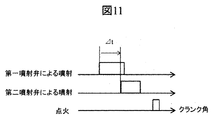
なお本実施例においては希薄燃焼運転時に図11に示すように、第1の燃料インジェクタによる噴射期間と第2の燃料インジェクタによる噴射期間が一部重複してもよい。第1の燃料インジェクタによる噴射開始時期に対して第2の燃料インジェクタによる噴射開始時期に遅れがあれば、第1の燃料インジェクタによって生成された空気流れと第2の燃料インジェクタによって生成された空気流れの相互干渉によって点火プラグ近傍に上昇流を生成して成層混合気を形成することができる。
また本実施例においては、希薄燃焼運転時に点火時期より前でかつ最も点火時期に近い燃料噴射が第2の燃料インジェクタで行い、点火時期より前でかつ点火時期から2番目に近い燃料噴射を前記第1の燃料噴射弁で行うものである。この条件を満たす範囲であれば、図12に示すようにこれら以外の噴射を伴ってもよく、その噴射時期、第1の燃料インジェクタと第2の燃料インジェクタの噴射順序は問わないものである。
また本実施例において制御部は図13に示すように、内燃機関の空燃比が大きい程、燃料噴射弁(第2の燃料インジェクタ9)から噴射される燃料噴射量に対する流体噴射弁(第1の燃料インジェクタ8)からの流体噴射量の比率を増加させるように流体噴射弁及び燃料噴射弁を制御する。すなわち、空燃比リッチ条件で点火プラグ10の方向に押し上げられる燃料量が多くなると過燃料リッチやPN悪化の要因になる。そこで、空燃比が小さくなるにつれて流体噴射弁の噴射割合を 小さくすることで、上記の燃料の押し上げ効果を小さくするものである。
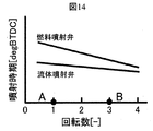
また本実施例において制御部は図14に示すように、内燃機関の回転数が大きい程、燃料噴射弁(第2の燃料インジェクタ9)の噴射タイミングに対する流体噴射弁(第1の燃料インジェクタ8)の噴射タイミングの差が小さくなるように流体噴射弁及び燃料噴射弁を制御する。
1…シリンダヘッド、2…シリンダブロック、3…ピストン、4…吸気管、5…排気管、6…吸気弁、7…排気弁、8…第1の燃料インジェクタ、9…第2の燃料インジェクタ、10…点火プラグ、11…点火コイル、12…燃料タンク、13…フィードポンプ、14…高圧燃料ポンプ、15…コモンレール、16…燃圧センサ、17…コンロッド、18…クランク軸、19…クランク角センサ、20…水温センサ、21…コレクタ、22…エンジンコントロールユニット、S1…第1の燃料インジェクタの噴射による燃料、S2…第2の燃料インジェクタの噴射による燃料、F1…第1の燃料インジェクタの噴射によるガス流動、F2…第2の燃料インジェクタの噴射によるガス流動、F13…第1の燃料インジェクタと第2の燃料インジェクタ噴射によって生じる上昇流、M12…混合気
Claims (11)
- 内燃機関を制御する内燃機関制御装置において、
前記内燃機関には、点火プラグの軸方向と沿うように設けられた流体噴射弁と、前記流体噴射弁とは別体で構成され、前記流体噴射弁の軸方向と交差する方向に設けられた燃料噴射弁と、が設けられ、
圧縮行程において、前記流体噴射弁から流体を噴射させた後、前記燃料噴射弁から流体を噴射させるように前記流体噴射弁及び前記燃料噴射弁を制御する制御部を備えたことを特徴とする内燃機関制御装置。 - 内燃機関を制御する内燃機関制御装置において、
前記内燃機関には、点火プラグと隣接して設けられた流体噴射弁と、前記流体噴射弁とは別体で構成され、前記流体噴射弁の軸方向と交差する方向に設けられた燃料噴射弁と、が設けられ、
圧縮行程において、前記流体噴射弁から流体を噴射させた後、前記燃料噴射弁から流体を噴射させるように前記流体噴射弁及び前記燃料噴射弁を制御する制御部を備えたことを特徴とする内燃機関制御装置。 - 請求項1又は2に記載の内燃機関制御装置において、
前記制御部は、前記内燃機関を理論混合比よりも燃料希薄な混合気で運転する場合で、かつ、前記内燃機関の圧縮行程において、前記流体噴射弁から流体を噴射させた後、前記燃料噴射弁から流体を噴射させるように前記流体噴射弁及び前記燃料噴射弁を制御することを特徴とする内燃機関制御装置。 - 請求項1又は2に記載の内燃機関制御装置において、
前記流体噴射弁の軸方向とシリンダ中心軸方向との成す角度が0°から45°の範囲であることを特徴とした内燃機関制御装置。 - 請求項1又は2に記載の内燃機関制御装置において、
前記点火プラグの点火時期よりも前のタイミングで前記燃料噴射弁の燃料噴射を行い、前記点火時期及び前記燃料噴射弁の燃料噴射よりも前のタイミングで前記流体噴射弁の流体噴射を行うことを特徴とした内燃機関制御装置。 - 請求項1に記載の内燃機関制御装置において、
前記制御部は、前記内燃機関の空燃比が大きい程、前記燃料噴射弁から噴射される燃料噴射量に対する前記流体噴射弁からの流体噴射量の比率を増加させるように前記流体噴射弁及び前記燃料噴射弁を制御することを特徴とする内燃機関制御装置。 - 請求項1に記載の内燃機関制御装置において、
前記制御部は、前記内燃機関の回転数が大きい程、前記燃料噴射弁の噴射タイミングに対する前記流体噴射弁の噴射タイミングの差が小さくなるように前記流体噴射弁及び前記燃料噴射弁を制御することを特徴とする内燃機関制御装置。 - 請求項1に記載の内燃機関制御装置において、
前記流体噴射弁は前記内燃機関の吸気管に対し排気側に設けられ、前記燃料噴射弁は前記内燃機関の排気管に対し吸気側に設けられたことを特徴とする内燃機関制御装置。 - 請求項1に記載の内燃機関制御装置において、
前記流体噴射弁及び燃料噴射弁は前記ピストンの中央部に向かう方向に配置されたことを特徴とする内燃機関制御装置。 - 請求項1に記載の内燃機関制御装置において、
前記流体噴射弁は前記内燃機関の上部に取り付けられ、前記燃料噴射弁は前記内燃機関の側面に取り付けられることを特徴とする内燃機関制御装置。 - 請求項1に記載の内燃機関制御装置において、
前記流体噴射弁は前記燃料噴射弁と同一形状の燃料噴射弁である内燃機関制御装置。
Priority Applications (3)
| Application Number | Priority Date | Filing Date | Title |
|---|---|---|---|
| US16/096,071 US20190107041A1 (en) | 2016-05-19 | 2017-03-22 | Internal Combustion Engine Control Device |
| EP17799008.2A EP3460223A4 (en) | 2016-05-19 | 2017-03-22 | COMBUSTION ENGINE CONTROL DEVICE |
| CN201780027278.XA CN109154248A (zh) | 2016-05-19 | 2017-03-22 | 内燃机控制装置 |
Applications Claiming Priority (2)
| Application Number | Priority Date | Filing Date | Title |
|---|---|---|---|
| JP2016-100046 | 2016-05-19 | ||
| JP2016100046A JP2017207011A (ja) | 2016-05-19 | 2016-05-19 | 内燃機関制御装置 |
Publications (1)
| Publication Number | Publication Date |
|---|---|
| WO2017199574A1 true WO2017199574A1 (ja) | 2017-11-23 |
Family
ID=60325888
Family Applications (1)
| Application Number | Title | Priority Date | Filing Date |
|---|---|---|---|
| PCT/JP2017/011296 Ceased WO2017199574A1 (ja) | 2016-05-19 | 2017-03-22 | 内燃機関制御装置 |
Country Status (5)
| Country | Link |
|---|---|
| US (1) | US20190107041A1 (ja) |
| EP (1) | EP3460223A4 (ja) |
| JP (1) | JP2017207011A (ja) |
| CN (1) | CN109154248A (ja) |
| WO (1) | WO2017199574A1 (ja) |
Families Citing this family (4)
| Publication number | Priority date | Publication date | Assignee | Title |
|---|---|---|---|---|
| JP7171531B2 (ja) * | 2019-09-24 | 2022-11-15 | 本田技研工業株式会社 | 燃料噴射制御装置 |
| CN111520245B (zh) * | 2020-03-20 | 2022-08-30 | 浙江吉利汽车研究院有限公司 | 一种发动机燃烧控制方法及系统 |
| JP7505470B2 (ja) * | 2021-10-14 | 2024-06-25 | トヨタ自動車株式会社 | 内燃機関 |
| WO2025029825A2 (en) * | 2023-07-31 | 2025-02-06 | The Board Of Trustees Of The University Of Alabama | Peripheral fuel injection for low emission and high efficiency diesel engines |
Citations (3)
| Publication number | Priority date | Publication date | Assignee | Title |
|---|---|---|---|---|
| JPH04187815A (ja) * | 1990-11-21 | 1992-07-06 | Toyota Motor Corp | 筒内直接噴射式火花点火機関 |
| JPH11159382A (ja) * | 1997-09-29 | 1999-06-15 | Mazda Motor Corp | 筒内噴射式エンジン |
| JP2001214744A (ja) * | 2000-02-03 | 2001-08-10 | Toyota Motor Corp | 筒内噴射式火花点火内燃機関 |
Family Cites Families (32)
| Publication number | Priority date | Publication date | Assignee | Title |
|---|---|---|---|---|
| US4414940A (en) * | 1981-04-13 | 1983-11-15 | Loyd Robert W | Conditioned compression ignition system for stratified charge engines |
| JPH07189875A (ja) * | 1993-12-28 | 1995-07-28 | Yamaha Motor Co Ltd | 2サイクルエンジンの燃料噴射装置 |
| JP3508481B2 (ja) * | 1997-07-08 | 2004-03-22 | 日産自動車株式会社 | 内燃機関の制御装置 |
| JPH1136959A (ja) * | 1997-07-24 | 1999-02-09 | Mitsubishi Motors Corp | 火花点火式筒内噴射型内燃機関 |
| US5832880A (en) * | 1997-07-28 | 1998-11-10 | Southwest Research Institute | Apparatus and method for controlling homogeneous charge compression ignition combustion in diesel engines |
| JP3693211B2 (ja) * | 1997-09-01 | 2005-09-07 | スズキ株式会社 | 筒内噴射式エンジン |
| GB2351357B (en) * | 1999-06-22 | 2001-05-02 | Terry Chou | Waterproof swimming goggles |
| JP3671785B2 (ja) * | 1999-12-15 | 2005-07-13 | 株式会社日立製作所 | 筒内噴射型内燃機関の燃料噴射装置 |
| EP1412634B1 (de) * | 2001-08-02 | 2006-11-22 | Cornel Stan | Gemischbildungs- und brennverfahren für wärmekraftmaschinen mit kraftstoff-direkteinspritzung |
| JP2004316568A (ja) * | 2003-04-17 | 2004-11-11 | Nissan Motor Co Ltd | 筒内直接噴射式内燃機関 |
| US6814046B1 (en) * | 2003-04-25 | 2004-11-09 | Nissan Motor Co., Ltd. | Direct fuel injection engine |
| US7028662B2 (en) * | 2003-11-06 | 2006-04-18 | Nissan Motor Co., Ltd. | Direct fuel injection engine |
| US20070022977A1 (en) * | 2005-07-27 | 2007-02-01 | Crower H B | Method and apparatus for operating an internal combustion engine |
| US7104250B1 (en) * | 2005-09-02 | 2006-09-12 | Ford Global Technologies, Llc | Injection spray pattern for direct injection spark ignition engines |
| JP4501832B2 (ja) * | 2005-09-29 | 2010-07-14 | マツダ株式会社 | 火花点火式直噴エンジン |
| JPWO2007066565A1 (ja) * | 2005-12-05 | 2009-05-14 | ヤマハ発動機株式会社 | エンジン |
| JP4380691B2 (ja) * | 2006-11-28 | 2009-12-09 | 日産自動車株式会社 | 副室式内燃機関 |
| US7574983B2 (en) * | 2006-12-01 | 2009-08-18 | Gm Global Technology Operations, Inc. | Method and apparatus for extending high load operation in a homogeneous charge compression ignition engine |
| JP2008267267A (ja) * | 2007-04-20 | 2008-11-06 | Nissan Motor Co Ltd | 内燃機関 |
| US7971567B2 (en) * | 2007-10-12 | 2011-07-05 | Ford Global Technologies, Llc | Directly injected internal combustion engine system |
| JP2009167878A (ja) * | 2008-01-15 | 2009-07-30 | Hitachi Ltd | ガソリンエンジン |
| US7712451B2 (en) * | 2008-05-07 | 2010-05-11 | Visteon Global Technologies, Inc. | Multi-fuel multi-injection system for an internal combustion engine |
| US7958872B1 (en) * | 2009-12-22 | 2011-06-14 | Michael Moses Schechter | Airless engine with gas and water recycling |
| CN101907025A (zh) * | 2010-06-28 | 2010-12-08 | 大连理工大学 | 内燃机多燃料燃烧系统 |
| DE102011015628B4 (de) * | 2010-10-07 | 2024-09-05 | Mercedes-Benz Group AG | Betriebsverfahren mit Wassereinspritzung |
| CA2870268C (en) * | 2011-04-11 | 2020-01-14 | Nostrum Energy Pte. Ltd. | Internally cooled high compression lean-burning internal combustion engine |
| JP5549641B2 (ja) * | 2011-05-23 | 2014-07-16 | 株式会社デンソー | 内燃機関の燃焼システム |
| JP5765819B2 (ja) * | 2012-04-11 | 2015-08-19 | 三菱重工業株式会社 | 2サイクルガスエンジン |
| DE102012214261A1 (de) * | 2012-08-10 | 2014-05-22 | Bayerische Motoren Werke Aktiengesellschaft | Brennkraftmaschine mit einem ersten und einem zweiten Injektor |
| EP3327277A1 (en) * | 2013-01-17 | 2018-05-30 | Nirmal Mulye | Method of operating an internal combustion engine |
| US9599057B2 (en) * | 2014-02-05 | 2017-03-21 | Ford Global Technologies, Llc | Method and system for selecting a cylinder for engine starting |
| US9714603B2 (en) * | 2014-07-23 | 2017-07-25 | Hyundai Motor Company | Dual pre-chamber combustion system |
-
2016
- 2016-05-19 JP JP2016100046A patent/JP2017207011A/ja active Pending
-
2017
- 2017-03-22 CN CN201780027278.XA patent/CN109154248A/zh active Pending
- 2017-03-22 EP EP17799008.2A patent/EP3460223A4/en not_active Withdrawn
- 2017-03-22 WO PCT/JP2017/011296 patent/WO2017199574A1/ja not_active Ceased
- 2017-03-22 US US16/096,071 patent/US20190107041A1/en not_active Abandoned
Patent Citations (3)
| Publication number | Priority date | Publication date | Assignee | Title |
|---|---|---|---|---|
| JPH04187815A (ja) * | 1990-11-21 | 1992-07-06 | Toyota Motor Corp | 筒内直接噴射式火花点火機関 |
| JPH11159382A (ja) * | 1997-09-29 | 1999-06-15 | Mazda Motor Corp | 筒内噴射式エンジン |
| JP2001214744A (ja) * | 2000-02-03 | 2001-08-10 | Toyota Motor Corp | 筒内噴射式火花点火内燃機関 |
Non-Patent Citations (1)
| Title |
|---|
| See also references of EP3460223A4 * |
Also Published As
| Publication number | Publication date |
|---|---|
| EP3460223A4 (en) | 2019-11-27 |
| CN109154248A (zh) | 2019-01-04 |
| US20190107041A1 (en) | 2019-04-11 |
| EP3460223A1 (en) | 2019-03-27 |
| JP2017207011A (ja) | 2017-11-24 |
Similar Documents
| Publication | Publication Date | Title |
|---|---|---|
| US7104250B1 (en) | Injection spray pattern for direct injection spark ignition engines | |
| JP6784214B2 (ja) | 内燃機関の制御装置 | |
| JP2002161790A (ja) | 直噴火花点火式内燃機関の燃焼制御装置 | |
| US10436134B2 (en) | Control device for internal combustion engine | |
| WO2017199574A1 (ja) | 内燃機関制御装置 | |
| JP2010048212A (ja) | 直噴ガソリンエンジン | |
| JP4506844B2 (ja) | 内燃機関 | |
| JP5783701B2 (ja) | 筒内噴射エンジンの制御装置 | |
| JP2017044174A (ja) | 燃料噴射弁 | |
| JP5274701B1 (ja) | 筒内噴射式内燃機関の制御装置 | |
| US20180010510A1 (en) | Control device for internal combustion engine | |
| JP2018003752A (ja) | 内燃機関 | |
| JP6402753B2 (ja) | 直噴エンジンの燃焼室構造 | |
| JP4492399B2 (ja) | 筒内直接噴射式火花点火内燃機関の制御装置および制御方法 | |
| JP5991251B2 (ja) | ディーゼルエンジンの燃料噴射制御装置 | |
| JP2014156852A (ja) | 圧縮着火エンジン | |
| US20190040814A1 (en) | Fuel Injection Valve Control Device | |
| JP5987734B2 (ja) | 圧縮着火エンジン | |
| WO2008102910A1 (ja) | 筒内噴射式内燃機関の燃料噴射制御装置 | |
| US20190145305A1 (en) | Fuel Injection Control Device | |
| JP2008202406A (ja) | 内燃機関の吸気バルブ制御装置及びこの制御装置を備えた内燃機関 | |
| JP6784267B2 (ja) | 燃料噴射装置および燃料噴射制御装置 | |
| JP2018003753A (ja) | 内燃機関の制御装置 | |
| Niculae et al. | About the constructive and functional particularities of spark ignition engines with gasoline direct injection | |
| JP2009144530A (ja) | 内燃機関の制御装置 |
Legal Events
| Date | Code | Title | Description |
|---|---|---|---|
| NENP | Non-entry into the national phase |
Ref country code: DE |
|
| 121 | Ep: the epo has been informed by wipo that ep was designated in this application |
Ref document number: 17799008 Country of ref document: EP Kind code of ref document: A1 |
|
| ENP | Entry into the national phase |
Ref document number: 2017799008 Country of ref document: EP Effective date: 20181219 |