WO2017199574A1 - Dispositif de commande de moteur à combustion interne - Google Patents
Dispositif de commande de moteur à combustion interne Download PDFInfo
- Publication number
- WO2017199574A1 WO2017199574A1 PCT/JP2017/011296 JP2017011296W WO2017199574A1 WO 2017199574 A1 WO2017199574 A1 WO 2017199574A1 JP 2017011296 W JP2017011296 W JP 2017011296W WO 2017199574 A1 WO2017199574 A1 WO 2017199574A1
- Authority
- WO
- WIPO (PCT)
- Prior art keywords
- injection valve
- internal combustion
- combustion engine
- fuel
- fluid
- Prior art date
- Legal status (The legal status is an assumption and is not a legal conclusion. Google has not performed a legal analysis and makes no representation as to the accuracy of the status listed.)
- Ceased
Links
Images








Classifications
-
- F—MECHANICAL ENGINEERING; LIGHTING; HEATING; WEAPONS; BLASTING
- F02—COMBUSTION ENGINES; HOT-GAS OR COMBUSTION-PRODUCT ENGINE PLANTS
- F02B—INTERNAL-COMBUSTION PISTON ENGINES; COMBUSTION ENGINES IN GENERAL
- F02B17/00—Engines characterised by means for effecting stratification of charge in cylinders
- F02B17/005—Engines characterised by means for effecting stratification of charge in cylinders having direct injection in the combustion chamber
-
- F—MECHANICAL ENGINEERING; LIGHTING; HEATING; WEAPONS; BLASTING
- F02—COMBUSTION ENGINES; HOT-GAS OR COMBUSTION-PRODUCT ENGINE PLANTS
- F02B—INTERNAL-COMBUSTION PISTON ENGINES; COMBUSTION ENGINES IN GENERAL
- F02B23/00—Other engines characterised by special shape or construction of combustion chambers to improve operation
- F02B23/08—Other engines characterised by special shape or construction of combustion chambers to improve operation with positive ignition
- F02B23/10—Other engines characterised by special shape or construction of combustion chambers to improve operation with positive ignition with separate admission of air and fuel into cylinder
-
- F—MECHANICAL ENGINEERING; LIGHTING; HEATING; WEAPONS; BLASTING
- F02—COMBUSTION ENGINES; HOT-GAS OR COMBUSTION-PRODUCT ENGINE PLANTS
- F02B—INTERNAL-COMBUSTION PISTON ENGINES; COMBUSTION ENGINES IN GENERAL
- F02B23/00—Other engines characterised by special shape or construction of combustion chambers to improve operation
- F02B23/08—Other engines characterised by special shape or construction of combustion chambers to improve operation with positive ignition
- F02B23/10—Other engines characterised by special shape or construction of combustion chambers to improve operation with positive ignition with separate admission of air and fuel into cylinder
- F02B23/104—Other engines characterised by special shape or construction of combustion chambers to improve operation with positive ignition with separate admission of air and fuel into cylinder the injector being placed on a side position of the cylinder
-
- F—MECHANICAL ENGINEERING; LIGHTING; HEATING; WEAPONS; BLASTING
- F02—COMBUSTION ENGINES; HOT-GAS OR COMBUSTION-PRODUCT ENGINE PLANTS
- F02D—CONTROLLING COMBUSTION ENGINES
- F02D41/00—Electrical control of supply of combustible mixture or its constituents
- F02D41/02—Circuit arrangements for generating control signals
-
- F—MECHANICAL ENGINEERING; LIGHTING; HEATING; WEAPONS; BLASTING
- F02—COMBUSTION ENGINES; HOT-GAS OR COMBUSTION-PRODUCT ENGINE PLANTS
- F02D—CONTROLLING COMBUSTION ENGINES
- F02D41/00—Electrical control of supply of combustible mixture or its constituents
- F02D41/02—Circuit arrangements for generating control signals
- F02D41/04—Introducing corrections for particular operating conditions
-
- F—MECHANICAL ENGINEERING; LIGHTING; HEATING; WEAPONS; BLASTING
- F02—COMBUSTION ENGINES; HOT-GAS OR COMBUSTION-PRODUCT ENGINE PLANTS
- F02D—CONTROLLING COMBUSTION ENGINES
- F02D41/00—Electrical control of supply of combustible mixture or its constituents
- F02D41/30—Controlling fuel injection
- F02D41/3011—Controlling fuel injection according to or using specific or several modes of combustion
- F02D41/3017—Controlling fuel injection according to or using specific or several modes of combustion characterised by the mode(s) being used
- F02D41/3023—Controlling fuel injection according to or using specific or several modes of combustion characterised by the mode(s) being used a mode being the stratified charge spark-ignited mode
-
- F—MECHANICAL ENGINEERING; LIGHTING; HEATING; WEAPONS; BLASTING
- F02—COMBUSTION ENGINES; HOT-GAS OR COMBUSTION-PRODUCT ENGINE PLANTS
- F02D—CONTROLLING COMBUSTION ENGINES
- F02D41/00—Electrical control of supply of combustible mixture or its constituents
- F02D41/30—Controlling fuel injection
- F02D41/3011—Controlling fuel injection according to or using specific or several modes of combustion
- F02D41/3017—Controlling fuel injection according to or using specific or several modes of combustion characterised by the mode(s) being used
- F02D41/3023—Controlling fuel injection according to or using specific or several modes of combustion characterised by the mode(s) being used a mode being the stratified charge spark-ignited mode
- F02D41/3029—Controlling fuel injection according to or using specific or several modes of combustion characterised by the mode(s) being used a mode being the stratified charge spark-ignited mode further comprising a homogeneous charge spark-ignited mode
-
- F—MECHANICAL ENGINEERING; LIGHTING; HEATING; WEAPONS; BLASTING
- F02—COMBUSTION ENGINES; HOT-GAS OR COMBUSTION-PRODUCT ENGINE PLANTS
- F02D—CONTROLLING COMBUSTION ENGINES
- F02D41/00—Electrical control of supply of combustible mixture or its constituents
- F02D41/30—Controlling fuel injection
- F02D41/3094—Controlling fuel injection the fuel injection being effected by at least two different injectors, e.g. one in the intake manifold and one in the cylinder
-
- F—MECHANICAL ENGINEERING; LIGHTING; HEATING; WEAPONS; BLASTING
- F02—COMBUSTION ENGINES; HOT-GAS OR COMBUSTION-PRODUCT ENGINE PLANTS
- F02D—CONTROLLING COMBUSTION ENGINES
- F02D41/00—Electrical control of supply of combustible mixture or its constituents
- F02D41/30—Controlling fuel injection
- F02D41/32—Controlling fuel injection of the low pressure type
- F02D41/34—Controlling fuel injection of the low pressure type with means for controlling injection timing or duration
-
- F—MECHANICAL ENGINEERING; LIGHTING; HEATING; WEAPONS; BLASTING
- F02—COMBUSTION ENGINES; HOT-GAS OR COMBUSTION-PRODUCT ENGINE PLANTS
- F02D—CONTROLLING COMBUSTION ENGINES
- F02D41/00—Electrical control of supply of combustible mixture or its constituents
- F02D41/30—Controlling fuel injection
- F02D41/32—Controlling fuel injection of the low pressure type
- F02D41/34—Controlling fuel injection of the low pressure type with means for controlling injection timing or duration
- F02D41/345—Controlling injection timing
-
- F—MECHANICAL ENGINEERING; LIGHTING; HEATING; WEAPONS; BLASTING
- F02—COMBUSTION ENGINES; HOT-GAS OR COMBUSTION-PRODUCT ENGINE PLANTS
- F02D—CONTROLLING COMBUSTION ENGINES
- F02D41/00—Electrical control of supply of combustible mixture or its constituents
- F02D41/30—Controlling fuel injection
- F02D41/38—Controlling fuel injection of the high pressure type
-
- F—MECHANICAL ENGINEERING; LIGHTING; HEATING; WEAPONS; BLASTING
- F02—COMBUSTION ENGINES; HOT-GAS OR COMBUSTION-PRODUCT ENGINE PLANTS
- F02D—CONTROLLING COMBUSTION ENGINES
- F02D41/00—Electrical control of supply of combustible mixture or its constituents
- F02D41/30—Controlling fuel injection
- F02D41/38—Controlling fuel injection of the high pressure type
- F02D41/40—Controlling fuel injection of the high pressure type with means for controlling injection timing or duration
- F02D41/402—Multiple injections
-
- F—MECHANICAL ENGINEERING; LIGHTING; HEATING; WEAPONS; BLASTING
- F02—COMBUSTION ENGINES; HOT-GAS OR COMBUSTION-PRODUCT ENGINE PLANTS
- F02F—CYLINDERS, PISTONS OR CASINGS, FOR COMBUSTION ENGINES; ARRANGEMENTS OF SEALINGS IN COMBUSTION ENGINES
- F02F1/00—Cylinders; Cylinder heads
- F02F1/24—Cylinder heads
-
- F—MECHANICAL ENGINEERING; LIGHTING; HEATING; WEAPONS; BLASTING
- F02—COMBUSTION ENGINES; HOT-GAS OR COMBUSTION-PRODUCT ENGINE PLANTS
- F02M—SUPPLYING COMBUSTION ENGINES IN GENERAL WITH COMBUSTIBLE MIXTURES OR CONSTITUENTS THEREOF
- F02M51/00—Fuel-injection apparatus characterised by being operated electrically
-
- F—MECHANICAL ENGINEERING; LIGHTING; HEATING; WEAPONS; BLASTING
- F02—COMBUSTION ENGINES; HOT-GAS OR COMBUSTION-PRODUCT ENGINE PLANTS
- F02M—SUPPLYING COMBUSTION ENGINES IN GENERAL WITH COMBUSTIBLE MIXTURES OR CONSTITUENTS THEREOF
- F02M61/00—Fuel-injectors not provided for in groups F02M39/00 - F02M57/00 or F02M67/00
- F02M61/14—Arrangements of injectors with respect to engines; Mounting of injectors
-
- F—MECHANICAL ENGINEERING; LIGHTING; HEATING; WEAPONS; BLASTING
- F02—COMBUSTION ENGINES; HOT-GAS OR COMBUSTION-PRODUCT ENGINE PLANTS
- F02D—CONTROLLING COMBUSTION ENGINES
- F02D41/00—Electrical control of supply of combustible mixture or its constituents
- F02D41/30—Controlling fuel injection
- F02D41/38—Controlling fuel injection of the high pressure type
- F02D2041/389—Controlling fuel injection of the high pressure type for injecting directly into the cylinder
-
- F—MECHANICAL ENGINEERING; LIGHTING; HEATING; WEAPONS; BLASTING
- F02—COMBUSTION ENGINES; HOT-GAS OR COMBUSTION-PRODUCT ENGINE PLANTS
- F02D—CONTROLLING COMBUSTION ENGINES
- F02D2200/00—Input parameters for engine control
- F02D2200/02—Input parameters for engine control the parameters being related to the engine
- F02D2200/10—Parameters related to the engine output, e.g. engine torque or engine speed
- F02D2200/101—Engine speed
-
- Y—GENERAL TAGGING OF NEW TECHNOLOGICAL DEVELOPMENTS; GENERAL TAGGING OF CROSS-SECTIONAL TECHNOLOGIES SPANNING OVER SEVERAL SECTIONS OF THE IPC; TECHNICAL SUBJECTS COVERED BY FORMER USPC CROSS-REFERENCE ART COLLECTIONS [XRACs] AND DIGESTS
- Y02—TECHNOLOGIES OR APPLICATIONS FOR MITIGATION OR ADAPTATION AGAINST CLIMATE CHANGE
- Y02T—CLIMATE CHANGE MITIGATION TECHNOLOGIES RELATED TO TRANSPORTATION
- Y02T10/00—Road transport of goods or passengers
- Y02T10/10—Internal combustion engine [ICE] based vehicles
- Y02T10/12—Improving ICE efficiencies
-
- Y—GENERAL TAGGING OF NEW TECHNOLOGICAL DEVELOPMENTS; GENERAL TAGGING OF CROSS-SECTIONAL TECHNOLOGIES SPANNING OVER SEVERAL SECTIONS OF THE IPC; TECHNICAL SUBJECTS COVERED BY FORMER USPC CROSS-REFERENCE ART COLLECTIONS [XRACs] AND DIGESTS
- Y02—TECHNOLOGIES OR APPLICATIONS FOR MITIGATION OR ADAPTATION AGAINST CLIMATE CHANGE
- Y02T—CLIMATE CHANGE MITIGATION TECHNOLOGIES RELATED TO TRANSPORTATION
- Y02T10/00—Road transport of goods or passengers
- Y02T10/10—Internal combustion engine [ICE] based vehicles
- Y02T10/40—Engine management systems
Definitions
- the present invention relates to an internal combustion engine control apparatus, and more particularly to an apparatus for controlling a fuel injection valve of a spark ignition type internal combustion engine.
- Stratified combustion is a method of reducing pump loss caused by throttle throttling by sucking air into the combustion chamber so that the operating air-fuel ratio becomes larger than the theoretical mixing ratio. It is necessary to stratify an air-fuel mixture with an appropriate equivalent ratio (approximately 1) in the vicinity of the spark plug.
- an object of the present invention is to form a stratified mixture stably around a spark plug.
- the present invention provides an internal combustion engine controller for controlling an internal combustion engine, wherein the internal combustion engine includes a fluid injection valve provided along an axial direction of a spark plug, and the fluid injection valve. And a fuel injection valve provided in a direction crossing the axial direction of the fluid injection valve, and after injecting fluid from the fluid injection valve in the compression stroke, the fuel injection A control unit is provided for controlling the fluid injection valve and the fuel injection valve so as to inject fluid from the valve.
- the structure in the intake pipe cross section of the Example of this invention is shown.
- the structure in the cylinder center cross section of the Example of this invention is shown.
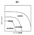
- a combustion mode switching map for engine speed and engine torque is shown.
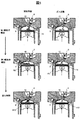
- the fuel injection with respect to combustion mode and the ignition timing chart are shown.
- the fuel behavior and gas flow in the Example of this invention are shown.
- the definition of the crossing angle ⁇ is shown.
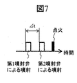
- requirement (DELTA) t is shown.
- a change in the demand ⁇ t with respect to the intersection angle ⁇ is shown.
- In-cylinder air flow when the crossing angle ⁇ is 90 ° is shown.
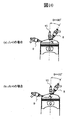
- (A) shows in-cylinder air flow when ⁇ t 0, and
- FIG. 1 shows an outline of the configuration
- FIG. 2 shows a mounting position of the fuel injector in the center section of the cylinder.
- a combustion chamber is formed by the cylinder head 1, the cylinder block 2, and the piston 3 inserted into the cylinder block, and the intake pipe 4 and the exhaust pipe 5 are branched into two for each cylinder and connected to the cylinder.
- Two intake valves 6 and two exhaust valves 7 are provided so as to open and close the opening.
- the intake valve 4 and the exhaust valve 5 have a cam operation method and rotate in conjunction with the crankshaft 16.
- the cam profile is generally used, and the top dead center is set when the exhaust valve closes and when the intake valve begins to open.
- the first fuel injector 8 does not necessarily have to be a fuel injector, and any fluid injection valve that injects fluid may be used. That is, in this embodiment, the internal combustion engine (direct injection engine) includes a fluid injection valve (first fuel injector 8) provided along the axial direction of the spark plug 10 and a fluid injection valve (first fuel).
- a fuel injection valve (second fuel injector 9) is provided separately from the injector 8) and provided in a direction intersecting the axial direction of the fluid injection valve (first fuel injector 8).
- the fluid injection valve (first fuel injector 8) is provided adjacent to the spark plug 10, and the angle formed between the axial direction of the fluid injection valve (first fuel injector 8) and the cylinder central axis direction is 0 °. To 45 °.
- the nozzle tips of the fluid injection valve and the fuel injection valve are inserted into the combustion chamber of the internal combustion engine.
- Fuel is stored in the fuel tank 12 and sent to the high-pressure pump 14 through the fuel pipe by the feed pump 13.
- the high-pressure fuel pump 14 is driven by an exhaust cam, and the pressurized fuel is sent to the common rail 15.
- the feed pump 13 can boost the fuel to about 0.3 MPa and send it to the high-pressure pump 14, and the high-pressure pump 14 can boost the fuel to about 15 MPa and send it to the common rail 15.
- a fuel pressure sensor 16 is installed on the common rail 15 so that the fuel pressure can be detected.
- a total of eight fuel injectors are connected to the tip of the common rail 16 for each cylinder.
- the piston 3 is connected to a crankshaft 18 via a connecting rod 17, and the engine speed can be detected by a crank angle sensor 19.
- a cell motor (not shown) is connected to the crankshaft 18 and can be started by rotating the crankshaft by the cell motor when the engine is started.
- a water temperature sensor 20 is attached to the cylinder block, and the temperature of the engine coolant can be detected.
- a collector 21 is connected upstream of the intake pipe 4.
- an air flow sensor and a throttle valve are provided upstream of the collector, and the amount of air taken into the combustion chamber can be adjusted by opening and closing the throttle. Although only one cylinder is shown in the figure, air is distributed from the collector to each cylinder.
- An engine control unit (ECU) 22 monitors signals from various sensors and is connected to control devices such as the first fuel injector 8, the second fuel injector 9, the spark plug 10, and the high-pressure fuel pump 14.
- control devices such as the first fuel injector 8, the second fuel injector 9, the spark plug 10, and the high-pressure fuel pump 14.
- the ECU 22 includes a CPU (Central Processing Unit) (not shown), and this CPU functions as a control unit for each device.
- FIG. This figure has shown an example of the operation mode with respect to the engine speed of the internal combustion engine and engine torque in a present Example.
- the internal combustion engine of this embodiment is operated in the stratified combustion mode when the engine speed and torque are low to medium.
- the stratified combustion mode is divided into a strong stratified combustion mode and a weak stratified combustion mode.
- the strong stratified combustion mode is used in a lower rotation and low torque region, and has a large air-fuel ratio (for example, A / F> 30), and increases the fuel concentration (stratification) around the spark plug 10.
- the weak stratified combustion mode is used in a higher rotation and high torque region, and the hollow fuel ratio (for example, 16 ⁇ A / F ⁇ 30) is set, and the stratified degree is set lower than that in the strong stratified combustion mode.
- the engine speed and torque are higher, the engine is operated in the homogeneous combustion mode.
- Fig. 4 shows a timing chart of fuel injection and ignition.
- fuel is injected within the intake stroke.
- strong stratified combustion mode at least two injections are performed within the compression stroke and before the ignition timing.
- weak stratified combustion mode at least one injection is performed in the intake stroke, and at least two injections are performed in the compression stroke and before the ignition timing.
- FIG. 5 shows the configuration of the fuel (spray and vaporized fuel) in the stratified combustion mode in the present embodiment in the combustion chamber and the flow direction of the gas flow.
- the control unit of the ECU 22 injects fluid from the fluid injection valve (first fuel injector 8) and then fluid from the fuel injection valve (second fuel injector 9) in the compression stroke.
- the injection timing of the fluid injection valve and the fuel injection valve is controlled so as to inject fuel.
- the control unit performs fuel injection of the fuel injection valve (second fuel injector 9) at a timing before the ignition timing of the spark plug 10, and before the ignition timing of the ignition plug 10 and the fuel injection of the fuel injection valve.
- the fluid injection valve (first fuel injector 8) is controlled to perform the fluid injection at the timing.
- the control unit performs the above-described control when the internal combustion engine is operated with an air-fuel mixture that is leaner than the theoretical mixture ratio and in the compression stroke of the internal combustion engine.
- the fuel S1 is injected in the form of spray from the first fuel injector 8 adjacent to the spark plug 10 toward the upper surface of the piston in the latter half of the compression stroke and before the ignition timing. Since a frictional drag acts between the fuel S1 and the in-cylinder gas, a gas flow F1 is formed from the nozzle tip of the first fuel injector 8 toward the second fuel injector 9 along the upper surface of the piston.
- the fuel S1 (spray) receives heat from the in-cylinder gas and the piston 3 and is vaporized in the vicinity of the upper surface of the piston.
- the fuel S2 is injected in the form of spray from the second fuel injector 9 toward the center of the combustion chamber before the ignition timing. Due to the frictional drag acting between the fuel S2 and the in-cylinder gas, a gas flow F2 is formed from the nozzle tip of the second fuel injector 9 toward the combustion chamber center along the upper surface of the piston. Since the flow direction of the gas flow F2 and the gas flow F1 formed by the fuel injection by the first fuel injector 8 are opposite to each other, they collide with each other near the upper surface of the piston below the spark plug, and the upward flow F12 Is formed. Further, the fuel S2 (spray) receives heat from the in-cylinder gas and the piston 3 and is vaporized in the vicinity of the upper surface of the piston.
- An air-fuel mixture M12 formed by mixing the fuel S1, the fuel S2 and the in-cylinder air is conveyed from the vicinity of the upper surface of the piston to the vicinity of the spark plug by the upward flow F12, and a stratified air-fuel mixture is formed around the spark plug 10.
- the vicinity of the spark plug 10 is close to the stoichiometric air-fuel ratio, so that reliable ignition and quick flame propagation are performed.
- the gas flows generated by the injection of the first fuel injector 8 and the second fuel injector 9 collide with each other, thereby creating an air flow from the piston 3 toward the spark plug 10, thereby generating fuel. Since it is conveyed in the vicinity of the spark plug 10, a stratified mixture can be stably formed even with respect to fluctuations in the rotational speed and load of the internal combustion engine. As a result, the lean combustion limit can be expanded, fuel efficiency can be improved, and exhaust gas CO2 and NOx can be reduced. Further, by collecting sufficiently vaporized fuel in the vicinity of the spark plug, the spark plug can be prevented from being beaten.
- the fluid injection valve (first fuel injector 8) is provided on the exhaust side of the intake pipe 4 of the internal combustion engine, and the fuel injection valve (second fuel injector 9) is intake of the exhaust pipe 5 of the internal combustion engine. It is desirable to be provided on the side. Further, as shown in FIG. 6, it is desirable that these fluid injection valves and fuel injection valves are arranged in a direction toward the central portion of the upper surface of the piston 3.
- the fluid injection valve is preferably attached to the upper part of the internal combustion engine, and the fuel injection valve is preferably attached to the side surface of the internal combustion engine. Further, the production cost can be reduced by making the fluid injection valve the same shape as the fuel injection valve.
- the crossing angle between the center axis of the first fuel injector 8 and the cylinder center axis is defined as ⁇ .
- the time difference between the injection start timing by the first fuel injector and the injection start timing by the second fuel injector is defined as ⁇ t.
- FIG. 8 shows the relationship between the crossing angle ⁇ and the required ⁇ t in the stratified mixture formation according to this example.
- the requirement ⁇ t is a necessary ⁇ t for forming a stratified mixture around the spark plug.
- the first fuel injector 8 and the second fuel injector 9 are arranged almost opposite to each other, and the gas flow generated by the injection from both fuel injectors In order to form an upward flow in the vicinity of the spark plug by interference, it is necessary to inject fuel from both fuel injectors almost simultaneously.
- the formation position of the upward flow is ignited as shown in FIG. 9B. Since it is closer to the second fuel injector 9 than the plug position, a stratified mixture cannot be formed around the spark plug.
- the crossing angle ⁇ is smaller than 90 °
- the jet generated by the injection of the first fuel injector 8 collides with the upper surface of the piston. Therefore, the smaller the crossing angle ⁇ , the second along the piston surface by the injection of the fuel injector 8.
- the position where the upward flow is formed is closer to the first fuel injector 8 than the position of the spark plug, and the stratified mixture cannot be formed around the spark plug.
- an appropriate range of ⁇ t> 0 is established, an upward flow is generated at the spark plug position by a gas flow generated by both injections as shown in FIG. 10B, and a stratified mixture is formed around the spark plug.
- the crossing angle ⁇ needs to be reduced to some extent, and the crossing angle ⁇ is preferably in the range of 0 ° to 45 °.
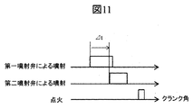
- the injection period by the first fuel injector and the injection period by the second fuel injector may partially overlap. If there is a delay in the injection start timing by the second fuel injector with respect to the injection start timing by the first fuel injector, the air flow generated by the first fuel injector and the air flow generated by the second fuel injector Due to the mutual interference, an upward flow can be generated in the vicinity of the spark plug to form a stratified mixture.
- the fuel injection before the ignition timing and closest to the ignition timing is performed by the second fuel injector in the lean combustion operation, and the fuel injection before the ignition timing and second closest to the ignition timing is performed. This is performed by the first fuel injection valve. As long as this condition is satisfied, injection other than these may be accompanied as shown in FIG. 12, and the injection timing and the injection order of the first fuel injector and the second fuel injector do not matter.
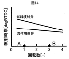
- the control unit increases the air fuel ratio of the internal combustion engine as the fluid injection valve (first fuel injection valve) with respect to the fuel injection amount injected from the fuel injection valve (second fuel injector 9).
- the fluid injection valve and the fuel injection valve are controlled so as to increase the ratio of the fluid injection amount from the fuel injector 8). That is, if the amount of fuel pushed up in the direction of the spark plug 10 under the air-fuel ratio rich condition increases, it causes overfuel richness and PN deterioration. Therefore, the fuel push-up effect is reduced by decreasing the injection ratio of the fluid injection valve as the air-fuel ratio decreases.
- control unit increases the rotational speed of the internal combustion engine, and the fluid injection valve (first fuel injector 8) with respect to the injection timing of the fuel injection valve (second fuel injector 9).
- the fluid injection valve and the fuel injection valve are controlled so as to reduce the difference in the injection timing.
- SYMBOLS 1 Cylinder head, 2 ... Cylinder block, 3 ... Piston, 4 ... Intake pipe, 5 ... Exhaust pipe, 6 ... Intake valve, 7 ... Exhaust valve, 8 ... 1st fuel injector, 9 ... 2nd fuel injector, DESCRIPTION OF SYMBOLS 10 ... Spark plug, 11 ... Ignition coil, 12 ... Fuel tank, 13 ... Feed pump, 14 ... High pressure fuel pump, 15 ... Common rail, 16 ... Fuel pressure sensor, 17 ... Connecting rod, 18 ... Crankshaft, 19 ... Crank angle sensor, DESCRIPTION OF SYMBOLS 20 ... Water temperature sensor, 21 ... Collector, 22 ...
Landscapes
- Engineering & Computer Science (AREA)
- Chemical & Material Sciences (AREA)
- Combustion & Propulsion (AREA)
- Mechanical Engineering (AREA)
- General Engineering & Computer Science (AREA)
- Combustion Methods Of Internal-Combustion Engines (AREA)
- Electrical Control Of Air Or Fuel Supplied To Internal-Combustion Engine (AREA)
- Cylinder Crankcases Of Internal Combustion Engines (AREA)
- Fuel-Injection Apparatus (AREA)
Abstract
Afin de résoudre le problème de formation d'un mélange air-carburant stratifié de manière stable autour d'une bougie d'allumage pendant une opération de combustion stratifiée, la présente invention concerne un dispositif de commande de moteur à combustion interne destiné à commander un moteur à combustion interne, et est caractérisé en ce que le moteur à combustion interne est pourvu de soupapes d'injection de fluide disposées le long de la direction axiale des bougies d'allumage, et de soupapes d'injection de carburant conçues en tant que corps séparés des soupapes d'injection de fluide et disposées dans une direction coupant la direction axiale des soupapes d'injection de fluide, et le dispositif de commande est équipé d'une unité de commande qui commande les soupapes d'injection de fluide et les soupapes d'injection de carburant de telle sorte que, pendant la course de compression, un fluide soit injecté à partir des soupapes d'injection de carburant après que le fluide a été injecté à partir des soupapes d'injection de fluide.
Priority Applications (3)
| Application Number | Priority Date | Filing Date | Title |
|---|---|---|---|
| US16/096,071 US20190107041A1 (en) | 2016-05-19 | 2017-03-22 | Internal Combustion Engine Control Device |
| EP17799008.2A EP3460223A4 (fr) | 2016-05-19 | 2017-03-22 | Dispositif de commande de moteur à combustion interne |
| CN201780027278.XA CN109154248A (zh) | 2016-05-19 | 2017-03-22 | 内燃机控制装置 |
Applications Claiming Priority (2)
| Application Number | Priority Date | Filing Date | Title |
|---|---|---|---|
| JP2016-100046 | 2016-05-19 | ||
| JP2016100046A JP2017207011A (ja) | 2016-05-19 | 2016-05-19 | 内燃機関制御装置 |
Publications (1)
| Publication Number | Publication Date |
|---|---|
| WO2017199574A1 true WO2017199574A1 (fr) | 2017-11-23 |
Family
ID=60325888
Family Applications (1)
| Application Number | Title | Priority Date | Filing Date |
|---|---|---|---|
| PCT/JP2017/011296 Ceased WO2017199574A1 (fr) | 2016-05-19 | 2017-03-22 | Dispositif de commande de moteur à combustion interne |
Country Status (5)
| Country | Link |
|---|---|
| US (1) | US20190107041A1 (fr) |
| EP (1) | EP3460223A4 (fr) |
| JP (1) | JP2017207011A (fr) |
| CN (1) | CN109154248A (fr) |
| WO (1) | WO2017199574A1 (fr) |
Families Citing this family (4)
| Publication number | Priority date | Publication date | Assignee | Title |
|---|---|---|---|---|
| JP7171531B2 (ja) * | 2019-09-24 | 2022-11-15 | 本田技研工業株式会社 | 燃料噴射制御装置 |
| CN111520245B (zh) * | 2020-03-20 | 2022-08-30 | 浙江吉利汽车研究院有限公司 | 一种发动机燃烧控制方法及系统 |
| JP7505470B2 (ja) * | 2021-10-14 | 2024-06-25 | トヨタ自動車株式会社 | 内燃機関 |
| WO2025029825A2 (fr) * | 2023-07-31 | 2025-02-06 | The Board Of Trustees Of The University Of Alabama | Injection de carburant périphérique pour moteurs diesel à faible émission et à haut rendement |
Citations (3)
| Publication number | Priority date | Publication date | Assignee | Title |
|---|---|---|---|---|
| JPH04187815A (ja) * | 1990-11-21 | 1992-07-06 | Toyota Motor Corp | 筒内直接噴射式火花点火機関 |
| JPH11159382A (ja) * | 1997-09-29 | 1999-06-15 | Mazda Motor Corp | 筒内噴射式エンジン |
| JP2001214744A (ja) * | 2000-02-03 | 2001-08-10 | Toyota Motor Corp | 筒内噴射式火花点火内燃機関 |
Family Cites Families (32)
| Publication number | Priority date | Publication date | Assignee | Title |
|---|---|---|---|---|
| US4414940A (en) * | 1981-04-13 | 1983-11-15 | Loyd Robert W | Conditioned compression ignition system for stratified charge engines |
| JPH07189875A (ja) * | 1993-12-28 | 1995-07-28 | Yamaha Motor Co Ltd | 2サイクルエンジンの燃料噴射装置 |
| JP3508481B2 (ja) * | 1997-07-08 | 2004-03-22 | 日産自動車株式会社 | 内燃機関の制御装置 |
| JPH1136959A (ja) * | 1997-07-24 | 1999-02-09 | Mitsubishi Motors Corp | 火花点火式筒内噴射型内燃機関 |
| US5832880A (en) * | 1997-07-28 | 1998-11-10 | Southwest Research Institute | Apparatus and method for controlling homogeneous charge compression ignition combustion in diesel engines |
| JP3693211B2 (ja) * | 1997-09-01 | 2005-09-07 | スズキ株式会社 | 筒内噴射式エンジン |
| GB2351357B (en) * | 1999-06-22 | 2001-05-02 | Terry Chou | Waterproof swimming goggles |
| JP3671785B2 (ja) * | 1999-12-15 | 2005-07-13 | 株式会社日立製作所 | 筒内噴射型内燃機関の燃料噴射装置 |
| EP1412634B1 (fr) * | 2001-08-02 | 2006-11-22 | Cornel Stan | Procede de formation de melange et de combustion pour moteurs thermiques a injection directe du carburant |
| JP2004316568A (ja) * | 2003-04-17 | 2004-11-11 | Nissan Motor Co Ltd | 筒内直接噴射式内燃機関 |
| US6814046B1 (en) * | 2003-04-25 | 2004-11-09 | Nissan Motor Co., Ltd. | Direct fuel injection engine |
| US7028662B2 (en) * | 2003-11-06 | 2006-04-18 | Nissan Motor Co., Ltd. | Direct fuel injection engine |
| US20070022977A1 (en) * | 2005-07-27 | 2007-02-01 | Crower H B | Method and apparatus for operating an internal combustion engine |
| US7104250B1 (en) * | 2005-09-02 | 2006-09-12 | Ford Global Technologies, Llc | Injection spray pattern for direct injection spark ignition engines |
| JP4501832B2 (ja) * | 2005-09-29 | 2010-07-14 | マツダ株式会社 | 火花点火式直噴エンジン |
| JPWO2007066565A1 (ja) * | 2005-12-05 | 2009-05-14 | ヤマハ発動機株式会社 | エンジン |
| JP4380691B2 (ja) * | 2006-11-28 | 2009-12-09 | 日産自動車株式会社 | 副室式内燃機関 |
| US7574983B2 (en) * | 2006-12-01 | 2009-08-18 | Gm Global Technology Operations, Inc. | Method and apparatus for extending high load operation in a homogeneous charge compression ignition engine |
| JP2008267267A (ja) * | 2007-04-20 | 2008-11-06 | Nissan Motor Co Ltd | 内燃機関 |
| US7971567B2 (en) * | 2007-10-12 | 2011-07-05 | Ford Global Technologies, Llc | Directly injected internal combustion engine system |
| JP2009167878A (ja) * | 2008-01-15 | 2009-07-30 | Hitachi Ltd | ガソリンエンジン |
| US7712451B2 (en) * | 2008-05-07 | 2010-05-11 | Visteon Global Technologies, Inc. | Multi-fuel multi-injection system for an internal combustion engine |
| US7958872B1 (en) * | 2009-12-22 | 2011-06-14 | Michael Moses Schechter | Airless engine with gas and water recycling |
| CN101907025A (zh) * | 2010-06-28 | 2010-12-08 | 大连理工大学 | 内燃机多燃料燃烧系统 |
| DE102011015628B4 (de) * | 2010-10-07 | 2024-09-05 | Mercedes-Benz Group AG | Betriebsverfahren mit Wassereinspritzung |
| CA2870268C (fr) * | 2011-04-11 | 2020-01-14 | Nostrum Energy Pte. Ltd. | Moteur a combustion interne a melange pauvre, a compression elevee et a refroidissement interne |
| JP5549641B2 (ja) * | 2011-05-23 | 2014-07-16 | 株式会社デンソー | 内燃機関の燃焼システム |
| JP5765819B2 (ja) * | 2012-04-11 | 2015-08-19 | 三菱重工業株式会社 | 2サイクルガスエンジン |
| DE102012214261A1 (de) * | 2012-08-10 | 2014-05-22 | Bayerische Motoren Werke Aktiengesellschaft | Brennkraftmaschine mit einem ersten und einem zweiten Injektor |
| EP3327277A1 (fr) * | 2013-01-17 | 2018-05-30 | Nirmal Mulye | Procédé de fonctionnement d'un moteur à combustion interne |
| US9599057B2 (en) * | 2014-02-05 | 2017-03-21 | Ford Global Technologies, Llc | Method and system for selecting a cylinder for engine starting |
| US9714603B2 (en) * | 2014-07-23 | 2017-07-25 | Hyundai Motor Company | Dual pre-chamber combustion system |
-
2016
- 2016-05-19 JP JP2016100046A patent/JP2017207011A/ja active Pending
-
2017
- 2017-03-22 CN CN201780027278.XA patent/CN109154248A/zh active Pending
- 2017-03-22 EP EP17799008.2A patent/EP3460223A4/fr not_active Withdrawn
- 2017-03-22 WO PCT/JP2017/011296 patent/WO2017199574A1/fr not_active Ceased
- 2017-03-22 US US16/096,071 patent/US20190107041A1/en not_active Abandoned
Patent Citations (3)
| Publication number | Priority date | Publication date | Assignee | Title |
|---|---|---|---|---|
| JPH04187815A (ja) * | 1990-11-21 | 1992-07-06 | Toyota Motor Corp | 筒内直接噴射式火花点火機関 |
| JPH11159382A (ja) * | 1997-09-29 | 1999-06-15 | Mazda Motor Corp | 筒内噴射式エンジン |
| JP2001214744A (ja) * | 2000-02-03 | 2001-08-10 | Toyota Motor Corp | 筒内噴射式火花点火内燃機関 |
Non-Patent Citations (1)
| Title |
|---|
| See also references of EP3460223A4 * |
Also Published As
| Publication number | Publication date |
|---|---|
| EP3460223A4 (fr) | 2019-11-27 |
| CN109154248A (zh) | 2019-01-04 |
| US20190107041A1 (en) | 2019-04-11 |
| EP3460223A1 (fr) | 2019-03-27 |
| JP2017207011A (ja) | 2017-11-24 |
Similar Documents
| Publication | Publication Date | Title |
|---|---|---|
| US7104250B1 (en) | Injection spray pattern for direct injection spark ignition engines | |
| JP6784214B2 (ja) | 内燃機関の制御装置 | |
| JP2002161790A (ja) | 直噴火花点火式内燃機関の燃焼制御装置 | |
| US10436134B2 (en) | Control device for internal combustion engine | |
| WO2017199574A1 (fr) | Dispositif de commande de moteur à combustion interne | |
| JP2010048212A (ja) | 直噴ガソリンエンジン | |
| JP4506844B2 (ja) | 内燃機関 | |
| JP5783701B2 (ja) | 筒内噴射エンジンの制御装置 | |
| JP2017044174A (ja) | 燃料噴射弁 | |
| JP5274701B1 (ja) | 筒内噴射式内燃機関の制御装置 | |
| US20180010510A1 (en) | Control device for internal combustion engine | |
| JP2018003752A (ja) | 内燃機関 | |
| JP6402753B2 (ja) | 直噴エンジンの燃焼室構造 | |
| JP4492399B2 (ja) | 筒内直接噴射式火花点火内燃機関の制御装置および制御方法 | |
| JP5991251B2 (ja) | ディーゼルエンジンの燃料噴射制御装置 | |
| JP2014156852A (ja) | 圧縮着火エンジン | |
| US20190040814A1 (en) | Fuel Injection Valve Control Device | |
| JP5987734B2 (ja) | 圧縮着火エンジン | |
| WO2008102910A1 (fr) | Dispositif de commande d'injection de carburant pour un moteur à combustion interne à injection dans le cylindre | |
| US20190145305A1 (en) | Fuel Injection Control Device | |
| JP2008202406A (ja) | 内燃機関の吸気バルブ制御装置及びこの制御装置を備えた内燃機関 | |
| JP6784267B2 (ja) | 燃料噴射装置および燃料噴射制御装置 | |
| JP2018003753A (ja) | 内燃機関の制御装置 | |
| Niculae et al. | About the constructive and functional particularities of spark ignition engines with gasoline direct injection | |
| JP2009144530A (ja) | 内燃機関の制御装置 |
Legal Events
| Date | Code | Title | Description |
|---|---|---|---|
| NENP | Non-entry into the national phase |
Ref country code: DE |
|
| 121 | Ep: the epo has been informed by wipo that ep was designated in this application |
Ref document number: 17799008 Country of ref document: EP Kind code of ref document: A1 |
|
| ENP | Entry into the national phase |
Ref document number: 2017799008 Country of ref document: EP Effective date: 20181219 |