WO2017199589A1 - Procédé d'estimation de comportement, système d'estimation de comportement, procédé de fourniture de service, procédé de détection de signal, unité de détection de signal et système de traitement de signal - Google Patents
Procédé d'estimation de comportement, système d'estimation de comportement, procédé de fourniture de service, procédé de détection de signal, unité de détection de signal et système de traitement de signal Download PDFInfo
- Publication number
- WO2017199589A1 WO2017199589A1 PCT/JP2017/012758 JP2017012758W WO2017199589A1 WO 2017199589 A1 WO2017199589 A1 WO 2017199589A1 JP 2017012758 W JP2017012758 W JP 2017012758W WO 2017199589 A1 WO2017199589 A1 WO 2017199589A1
- Authority
- WO
- WIPO (PCT)
- Prior art keywords
- signal
- acceleration
- detection
- sensor
- unit
- Prior art date
- Legal status (The legal status is an assumption and is not a legal conclusion. Google has not performed a legal analysis and makes no representation as to the accuracy of the status listed.)
- Ceased
Links
Images

















Classifications
-
- B—PERFORMING OPERATIONS; TRANSPORTING
- B66—HOISTING; LIFTING; HAULING
- B66B—ELEVATORS; ESCALATORS OR MOVING WALKWAYS
- B66B5/00—Applications of checking, fault-correcting, or safety devices in elevators
- B66B5/0006—Monitoring devices or performance analysers
- B66B5/0018—Devices monitoring the operating condition of the elevator system
- B66B5/0025—Devices monitoring the operating condition of the elevator system for maintenance or repair
-
- A—HUMAN NECESSITIES
- A61—MEDICAL OR VETERINARY SCIENCE; HYGIENE
- A61B—DIAGNOSIS; SURGERY; IDENTIFICATION
- A61B5/00—Measuring for diagnostic purposes; Identification of persons
- A61B5/103—Measuring devices for testing the shape, pattern, colour, size or movement of the body or parts thereof, for diagnostic purposes
- A61B5/11—Measuring movement of the entire body or parts thereof, e.g. head or hand tremor or mobility of a limb
-
- A—HUMAN NECESSITIES
- A61—MEDICAL OR VETERINARY SCIENCE; HYGIENE
- A61B—DIAGNOSIS; SURGERY; IDENTIFICATION
- A61B5/00—Measuring for diagnostic purposes; Identification of persons
- A61B5/103—Measuring devices for testing the shape, pattern, colour, size or movement of the body or parts thereof, for diagnostic purposes
- A61B5/11—Measuring movement of the entire body or parts thereof, e.g. head or hand tremor or mobility of a limb
- A61B5/1107—Measuring contraction of parts of the body, e.g. organ or muscle
-
- A—HUMAN NECESSITIES
- A61—MEDICAL OR VETERINARY SCIENCE; HYGIENE
- A61B—DIAGNOSIS; SURGERY; IDENTIFICATION
- A61B5/00—Measuring for diagnostic purposes; Identification of persons
- A61B5/103—Measuring devices for testing the shape, pattern, colour, size or movement of the body or parts thereof, for diagnostic purposes
- A61B5/11—Measuring movement of the entire body or parts thereof, e.g. head or hand tremor or mobility of a limb
- A61B5/1121—Determining geometric values, e.g. centre of rotation or angular range of movement
-
- A—HUMAN NECESSITIES
- A61—MEDICAL OR VETERINARY SCIENCE; HYGIENE
- A61B—DIAGNOSIS; SURGERY; IDENTIFICATION
- A61B5/00—Measuring for diagnostic purposes; Identification of persons
- A61B5/103—Measuring devices for testing the shape, pattern, colour, size or movement of the body or parts thereof, for diagnostic purposes
- A61B5/11—Measuring movement of the entire body or parts thereof, e.g. head or hand tremor or mobility of a limb
- A61B5/1123—Discriminating type of movement, e.g. walking or running
-
- A—HUMAN NECESSITIES
- A61—MEDICAL OR VETERINARY SCIENCE; HYGIENE
- A61B—DIAGNOSIS; SURGERY; IDENTIFICATION
- A61B5/00—Measuring for diagnostic purposes; Identification of persons
- A61B5/22—Ergometry; Measuring muscular strength or the force of a muscular blow
-
- A—HUMAN NECESSITIES
- A61—MEDICAL OR VETERINARY SCIENCE; HYGIENE
- A61B—DIAGNOSIS; SURGERY; IDENTIFICATION
- A61B5/00—Measuring for diagnostic purposes; Identification of persons
- A61B5/72—Signal processing specially adapted for physiological signals or for diagnostic purposes
- A61B5/7235—Details of waveform analysis
- A61B5/7253—Details of waveform analysis characterised by using transforms
- A61B5/7257—Details of waveform analysis characterised by using transforms using Fourier transforms
-
- A—HUMAN NECESSITIES
- A61—MEDICAL OR VETERINARY SCIENCE; HYGIENE
- A61B—DIAGNOSIS; SURGERY; IDENTIFICATION
- A61B2503/00—Evaluating a particular growth phase or type of persons or animals
- A61B2503/20—Workers
-
- A—HUMAN NECESSITIES
- A61—MEDICAL OR VETERINARY SCIENCE; HYGIENE
- A61B—DIAGNOSIS; SURGERY; IDENTIFICATION
- A61B2562/00—Details of sensors; Constructional details of sensor housings or probes; Accessories for sensors
- A61B2562/02—Details of sensors specially adapted for in-vivo measurements
- A61B2562/0219—Inertial sensors, e.g. accelerometers, gyroscopes, tilt switches
-
- A—HUMAN NECESSITIES
- A61—MEDICAL OR VETERINARY SCIENCE; HYGIENE
- A61B—DIAGNOSIS; SURGERY; IDENTIFICATION
- A61B5/00—Measuring for diagnostic purposes; Identification of persons
- A61B5/103—Measuring devices for testing the shape, pattern, colour, size or movement of the body or parts thereof, for diagnostic purposes
- A61B5/11—Measuring movement of the entire body or parts thereof, e.g. head or hand tremor or mobility of a limb
- A61B5/1118—Determining activity level
Definitions
- Embodiment of this invention is related with the action estimation technique using the detection signal from the active mass meter with which the measuring subject was mounted
- the present invention is not limited to this, and the detection technology of signals obtained from sensors or the estimation technology or service provision technology using the same is also included.
- the activity meter not only the activity meter, but also the noise components of disturbance mixed in the detection signals from many sensors greatly affect the detection environment and detection state. As a result, the detection accuracy using the sensor varies depending on the detection environment and detection state.
- Patent Document 1 discloses detection from an acceleration sensor.
- the low frequency component of the signal is removed using a high pass filter.
- the component of the detection signal is included in the low frequency band. Therefore, in this method, there is a risk of removing the detection signal.
- Patent Document 1 discloses that the “amplitude of the detection signal from the acceleration sensor” The ratio between “size” and “period” is calculated so that it can be easily discriminated. However, even if the calculation is performed as described above, the estimation accuracy still decreases in a detection environment in which disturbance noise components are largely mixed.
- the coordinate system of the measurement acceleration can be estimated using the angle between the operator's (measurement target) arm and the trolley extracted from the gravity acceleration value of the gravity. Convert to And a worker's action is presumed using the detection signal after the conversion. Furthermore, the accuracy of behavior estimation is improved while automatically correcting the behavior estimation conditions.
- coordinate conversion of a plurality of detection signal waveforms is performed using an angle between a reference direction such as a gravitational direction and an action direction of a measurement subject, and the measurement is performed based on the result. Estimate the behavior of the target person or provide the service.
- the action direction may correspond to, for example, the direction in which the measurement subject pushes the carriage or the angle of the arm that holds the carriage.
- the accuracy of action estimation can be improved without preparing and using individual correct waveform data corresponding to each worker whose estimation is to be measured.
- a sensor device that can be worn on a human body and can detect some activity amount of the wearer using a detection signal obtained therefrom is referred to as an activity meter in this specification.
- the activity meter (sensor device) 4 is attached to the arm or leg of the wearer (measurement subject 2).
- the detection target 2 wearing the activity meter 4 pushes the carriage 122 and detects from the activity meter 4.
- the activity meter may be embedded in a part of a wearing item or clothing (clothing) such as a hat, glasses, or shoes worn by the human body.
- the basic contents of this embodiment are: (1) Obtain a detection raw signal obtained from an activity meter attached to a human body (or animal), (2) Extract the reference using the obtained detection raw signal, (3) signal processing from the detected raw signal based on the extracted reference; (4) Estimate the behavior (or state or request) of the human body (or animal) based on the signal processing results, (5) Analyzing the action history (for example, work / working) for each measurement target person (worker), (6) Perform processing in accordance with the flow of (1) to (6) to connect the analysis result to business improvement (improvement of work process) (may be omitted in some cases). Further, not limited to this process, the process of (7) providing an appropriate service may be performed using the estimation results obtained in (1) to (4). Furthermore, the system according to the present embodiment is not limited thereto, and may be arbitrarily utilized using the above estimation result.
- the present embodiment further fixes a sensor device to a predetermined object (other than a person or an animal), estimates a state related to the predetermined object based on a detection signal obtained from the sensor device, Service provision may be performed based on this.
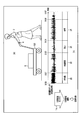
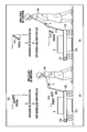
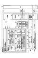
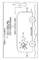
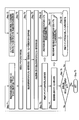
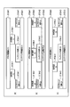
- FIG.1 (b) has shown the change of the measurement object person 2 for every elapsed time, and the change of the detection raw signal (acceleration waveform) acquired from the active mass meter 4 at the time of each action.
- the person to be measured 2 ⁇ Perform manual operation 20 from 9am to 9am, ⁇ After moving the carriage 22 between 9:01 and 9:03, ⁇ Until 24: 9, temporarily stop 24. ⁇ Walk from 9: 4 to 9: 6.
- the activity meter 4 obtains a unique detection signal (acceleration waveform) for each action.
- the behavior of the measurement subject 2 can be estimated by using the behavior estimation engine 14 and extracting the characteristics of these unique (original) detection raw signals (acceleration waveforms).
- the detection raw signal (acceleration waveform) acquired from the activity meter 4 is temporarily stored in the memory unit (output waveform data storage unit from the sensor) (corresponding to the processing of (1) above), and the memory unit (2) Reference extraction and (3) Signal processing, (4) Behavior estimation, (5) History analysis, (6) Work using the detection raw signal (acceleration waveform) read from (output waveform data storage unit) A series of processing until planning for improvement 10 is performed.
- the present invention is not limited to this, and the processing (2) to (6) may be performed in real time on the detected raw signal (acceleration waveform) in contrast to the processing (1) acquired from the activity meter 4 (1). . Furthermore, based on the behavior estimation result 16, the process (7) (providing appropriate services) may be performed.
- Direction is preset.
- the relationship between these axes and a predetermined reference is, for example, a measurement subject wearing an activity meter 4 as shown in FIG.
- the direction from the second arm 120 toward the middle finger is set as the Y axis.
- the action direction 100 (direction in which the measurement subject 2 exerts a force) when the measurement subject 2 pushes the carriage is matched with the Y-axis direction.
- the axis direction perpendicular to the back of the measurement subject's hand is set as the Z-axis direction
- the direction perpendicular to the Y-axis and the Z-axis (the direction from the little finger of the measurement subject 2 to the thumb) is set as the X-axis.
- magnetic field strength signals in the X-axis, Y-axis, and Z-axis directions are obtained from the triaxial geomagnetic sensor 74.
- a direction along the reference A (geomagnetic direction) 102 is defined as a y-axis (a direction from the south pole direction 114 toward the north pole direction 112).
- a direction from the west direction to the east direction is defined as the x-axis.
- the detection raw signals WX (t), WY (t), and WZ (t) are obtained from the triaxial acceleration sensor 72 (FIG. 17) built in the activity meter 4, respectively.
- the activity meter data (acceleration waveform) 12 shown in FIG. 1 corresponds to WZ (t) (or WY (t)).
- the detection raw signals WX (t), WY (t), and WZ (t) that are sequentially collected with the passage of time are sequentially stored in the memory unit (output waveform data storage unit) 82 in FIG.
- the detection raw signals WX (t), WY (t), and WZ (t) stored in the memory unit (output waveform data storage unit) 82 at a time are continuous actions of the measurement subject 2 for 2 to 3 hours. Data corresponding to can be used. In addition, the action data of the measurement subject 2 for one day may be stored at a time.
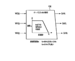
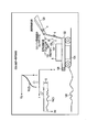
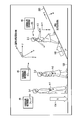
- FIG. 2 shows a method of extracting the reference B (gravity direction) 104 by using the signal components Q41L and Q42L subjected to the low-pass filter processing indicating the acceleration.
- the low-frequency component Q42L of the detection raw signal WY (t) acquired in the Y-axis direction the low-frequency component Q41L of the detection raw signal WZ (t) acquired in the Z-axis direction, and the gravitational acceleration component G facing the z-axis direction
- the gravitational acceleration component G facing the z-axis direction
- the angle ⁇ yz can be calculated by using any one of the above formulas (1), (2), and (3).
- the functions of the reference direction extraction 92 and the angle extraction 94 described in FIGS. 12 and 13 calculate the angle ⁇ by extracting the reference B (gravity) 104 from the detected raw signal using FIGS. 3 and 2. This corresponds to the function and the function of calculating the angle ⁇ by extracting the reference A (geomagnetic direction) 102 from the detected raw signal using FIG. 2 and FIG.
- the function of the detection signal generation (signal processing) 96 after the noise component reduction described in FIGS. 12 and 13 is based on the detection raw signals WX (t), WY (t), and WZ (t) from Equation (4) to This corresponds to the function of converting the detection signal “WY (t)
- ⁇ yz ⁇ s” or Wy (t) in a predetermined direction by performing signal processing using the equation (7).
- the vibration is mixed into the detected raw signals WX (t), WY (t), and WZ (t) as disturbance noise components.
- the frequency resulting from the vibration of the arm 120 of the measurement subject 2 is often 0.5 Hz or more.
- the signal components Q41L, Q42L, and Q43L after the low-pass filter processing 138 is performed on the detected raw signals WZ (t), WY (t), and WX (t) are extracted as described above. Disturbance noise component can be reduced.
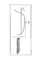
- the characteristic of the gain g with respect to the frequency f of this low-pass filter is the characteristic shown in FIG. 3, it is possible to extract only the signal component below the cutoff frequency fc.
- the value of the cut-off frequency fc when performing the low-pass filter processing 138 can be set to 60 Hz or 50 Hz from the above description, or may be set to 0.5 Hz.
- any filter processing may be employed in the present embodiment.
- band pass filter processing for extracting only specific frequency components may be performed.
- the arm and carriage 122 of the measurement subject 2 extracted from the gravity acceleration values are extracted.
- a method of converting the coordinate system of the measurement acceleration into a coordinate system capable of estimating the action of the measurement subject 2 will be described.
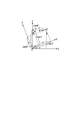
- FIG. 4 shows a coordinate conversion situation between the y-axis / z-axis and the Y-axis / Z-axis when the X-axis and the x-axis coincide.
- the conversion equation between the detection waveform Wy (t) / Wz (t) after the conversion process and the detection raw signal WY (t) / WZ (t) is
- the detection raw signals WX (t), WY (t), WZ (t) obtained from the triaxial acceleration sensor 72 (or the triaxial geomagnetic sensor 74) are used as the reference A (the geomagnetic direction).
- Converted detection signals Wx (t), Wy (t) estimated to be obtained in the directions of the y-axis parallel to 102 and the z-axis (and the x-axis orthogonal to them) parallel to the reference B (gravity) 104 ), Wz (t) can be calculated.
- a triaxial acceleration sensor 72 (or triaxial geomagnetic sensor 74) is used as the sensor, a plurality of sensors that change over time such as Wx (t), Wy (t), and Wz (t) from one or a plurality of sensors.
- the detected raw signal is collected. Then, for example, as a result of uneven distribution of noise components by signal processing across a plurality of detection raw signals using the characteristics of the obtained detection raw signals (extraction of predetermined unique information such as ⁇ yz included therein)
- the noise component of a predetermined detection signal for example, Wy (t) after signal processing Is effective.
- a specific signal component included in the detection raw signal is extracted by signal processing across the plurality of detection raw signals (for example, extraction of gravity acceleration value G using equation (1), etc.). May be.
- signal processing may be performed across a plurality of detection raw signals collected simultaneously from a plurality of different types of sensors such as the triaxial acceleration sensor 72 and the triaxial angular velocity sensor 212.
- predetermined unique information included in the detection raw signal means “the rotation direction 218 of the handle 214” or “the acceleration of the bus / truck, passenger car 210 / “Deceleration direction”, “Bus or truck, direction of change of traveling direction of passenger car 210”, and the like.
- identification of a specific sensor mounting direction (a direction of a predetermined coordinate axis installed in the specific sensor) and a specific signal component (for example, “acceleration / deceleration”, the acceleration of the detected acceleration at the start of acceleration / deceleration)
- a specific signal component for example, “acceleration / deceleration”, the acceleration of the detected acceleration at the start of acceleration / deceleration
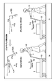
- the handling for the standard height measurement subject 140 and the lower height measurement subject 142 or the higher height measurement subject 144 will be described.
- the angle ⁇ yz when the measurement subject 142 whose height is lower than the standard presses the carriage 122 is ⁇ yz ⁇ compared with the angle ⁇ s when the measurement subject 140 of the standard height pushes the carriage 122.
- the angle ⁇ yz when the measurement subject 144 whose height is higher than the standard pushes the carriage 122 is ⁇ yz> ⁇ s.
- a feedback method (a kind of learning) related to a threshold used in processing of action estimation for a measurement subject 142 having a height lower than the standard height or a measurement subject 144 having a height higher than the standard height. Function).
- the measurement subject 144 whose height is higher than the standard pushes the carriage 122 (FIG. 7A)
- the value of the angle ⁇ yz formed by the action direction 100 and the direction in which the carriage 122 moves (y axis) increases.
- the force by which the person to be measured 144 presses the carriage 122 against the floor surface is increased.
- the dynamic frictional force and the static frictional force of the carriage 122 become large, and the carriage 122 becomes difficult to move.
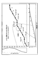
- FIG. 8 is based on the angle ⁇ s, and the error amount between the standard measurement acceleration after conversion with respect to the angle ⁇ yz when the measurement subject 2 pushes the carriage 122 and the measurement acceleration waveform (detected raw signal) or the standard measurement acceleration waveform (sample data). The relationship between the Euclidean distance compared to) is shown.
- the characteristic shown in FIG. 8 is a value sufficiently smaller than the determination threshold 150 when estimating the behavior of the measurement subject.
- the determination threshold 150 at the time of behavior estimation is automatically corrected (the determination value 150 is set to a larger value).
- FIG. 4 which is the basis for deriving the above equation (4) is a diagram in which the y-axis and the z-axis are rotated by ⁇ yz while the X-axis and the x-axis are matched (vertical rotation). The coordinate transformation of the three-dimensional transformation is shown.
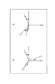
- FIG. 9A shows a diagram (horizontal rotation coordinate conversion... Rotation conversion) in which the z axis and the x axis are rotated by ⁇ zx while the Y axis and the y axis coincide with each other and converted to the Z axis and the X axis.
- FIG. 9B shows a diagram in which the x-axis and the y-axis are rotated by ⁇ xy while the Z-axis and the z-axis coincide with each other and converted into the X-axis and the Y-axis.
- ⁇ yz> ⁇ s” is used to perform signal processing to convert the detection signal into a Wy (t) detection signal with less noise components. Think about when you can. Then, in the above signal processing, the detection raw signal “WY (t)
- ⁇ yz ⁇ s
- WY (t) WY (t)
- ⁇ yz ⁇ s
- the angle between the Z-axis and the Zs-axis and the angle between the X-axis and the Xs-axis when the Y-axis and the Ys-axis coincide with each other are represented by d ⁇ zx.
- the angle between the X-axis and the Xs-axis and the angle between the Y-axis and the Ys-axis when the Z-axis and the Zs-axis coincide with each other are represented by d ⁇ xy.
- measured acceleration waveforms (detected raw signals) WX (t), WY (t), obtained from the activity meter 4 worn by the measurement subject 142 lower than the standard height or the measurement subject 144 higher than the standard height
- WZ (t) is converted into WXs (t), WYs (t), WZs (t) (standard measurement acceleration after conversion to the corresponding standard height), and based on the detection signal (standard measurement acceleration) after conversion
- FIG. As a result, there is an effect that the behavior estimation with respect to the measurement subjects 140 to 144 can be performed with high accuracy on a common scale regardless of the height difference of the measurement subjects 140 to 144.
- the method of using the rotation coordinate conversion between the coordinate axes shown in FIG. 4 has been described as a method of converting into a detection signal that reduces the influence of the height of the measurement subject 2 by signal processing.
- the present embodiment is not limited to this, and in the present embodiment, any other signal processing is possible as long as the signal processing uses the detection raw signals Wx (t), Wy (t), and Wz (t) obtained from the various sensors 72 and 74.
- a method may be used.
- the detection raw signals Wx (t), Wy (t), and Wz (t) may be regarded as three-dimensional vectors, and vector calculation processing (for example, vector synthesis processing) between the vector components may be performed.
- the present invention is not limited to this, signal processing across the detection raw signals obtained from a plurality of different sensors 72 and 74 is performed, and detection signal generation (signal processing) 96 (FIG. 12 or FIG. 13) after noise component reduction is performed. May be. That is, in the conversion between the detection signals using the equation (4) calculated using FIG. 4, for example, the conversion between the detection signals obtained only from the triaxial acceleration sensor 72 is performed.
- the present invention is not limited to this.
- signal processing in which detection signals obtained from the triaxial geomagnetic sensor 74 are also combined may be performed to reduce the noise component of the detection raw signal.
- the angle ⁇ yz of the arm 120 of the person 2 to be measured when the carriage 122 is pushed changes with time. Therefore, it is necessary to repeat the process of calculating the detection signal after rotation conversion (signal processing) many times.
- One or more of the detection raw signals WX (t), WY (t), and WZ (t) collected from the triaxial acceleration sensor 72 are referred to as “measurement acceleration waveform (detection raw signal)”.
- ⁇ yz ⁇ s, WY (t) collected from the triaxial acceleration sensor 72 obtained directly when the measurement subject 140 (FIG. 5 or FIG. 6) of the standard height pushes the carriage 122
- ⁇ yz ⁇ s, WZ (t)
- the standard acceleration (detected raw signal) is stored in the memory unit 82 (FIG. 12) and used as reference data (sample data) at the time of behavior estimation
- the standard stored in the memory unit 82 is used.
- the acceleration (detected raw signal) is referred to as “standard measurement acceleration waveform (sample data)”.
- the standard measurement acceleration waveform (sample data) may be sample data collected only once from the measurement subject 140 having a single standard height, or may be an average value of data collected multiple times or a plurality of standard heights. An average value of data obtained from the measurement subject 140 may be used.
- cycle the processing from “collection of detection raw signal ⁇ signal processing (rotation conversion of detection signal)” is described as “cycle”.
- cycle frequency The number of cycles repeated per second
- cycle period the time required for one cycle.
- the cycle period corresponds to the “resolution” (information collection speed) of the cycle process.
- the accumulation period of data of standard measurement acceleration after conversion necessary for statistical processing is referred to as “statistic processing accumulation period”.
- This behavior estimation unit period (a period for collecting statistical processing results) is referred to as a “behavior estimation determination period”.
- the cycle frequency in the system of the present embodiment (behavior estimation system 52), the higher the resolution of the cycle processing, and the easier the detection of the measurement subject 2's behavior change.
- the action (work) of the person to be measured 2 changes from manual work 20 to cart movement 22, stationary, walking 26 every minute or every two minutes.
- the behavior (work) of the measurement subject 2 may change more frequently.
- the cycle period in this embodiment is set to 10 seconds or less at the longest.
- the cycle period in this embodiment is preferably 0.5 seconds or less.
- the description will be continued by temporarily setting 20 Hz as an example of the cycle frequency.
- the value of the cut-off frequency fc when extracting a predetermined reference is set to 50 Hz or 60 Hz
- the value of the cut-off frequency fc has a certain degree of consistency with the aforementioned cycle frequency of 20 Hz.
- the cutoff frequency fc is set to a low value such as 0.5 Hz
- the low-pass filter processing 138 may be performed using the detection raw signal for a plurality of cycles.
- the system (signal processing system) of this embodiment detection from the triaxial acceleration sensor 72 and the triaxial geomagnetic sensor 74 (converted into a digital signal by the A / D converter 78 via the signal amplifier group 76).
- the raw signal is temporarily stored in the memory unit 82, and then read out in response to an instruction from the control unit 80 and processed. Therefore, the low-pass filter processing 138 using the detection raw signal for a plurality of cycles is facilitated.
- the present invention is not limited thereto, and signal processing in real time may be performed by properly using the processing of the memory unit 82.
- the statistical processing accumulation period described above will be described. For example, it is meaningless to perform statistical processing on data of only one cycle. In order to perform effective statistical processing, it is desirable to accumulate data of at least 4 cycles, preferably 10 cycles or more. For example, when the cycle frequency is 20 Hz (cycle period 50 mS), the accumulation period for statistical processing requires 0.5 seconds to accumulate data for 10 cycles.
- the behavior estimation determination period needs to be at least four times (preferably at least eight times) the statistical processing accumulation period. For the above reason, 4 seconds may be set as the action estimation determination period.
- the relationship between the periods is “behavior estimation judgment period” ⁇ “statistical processing accumulation period” ⁇ “cycle period”.
- A Dispersion between detection signals before and after rotation conversion (signal processing) and irregularity determination (A1) Z-axis direction (gravity component) or Y-axis direction (trolley movement direction) for each statistical processing accumulation period described above )
- A1 Z-axis direction (gravity component) or Y-axis direction (trolley movement direction) for each statistical processing accumulation period described above
- the measured acceleration waveform (detected raw signal) and the converted standard measured acceleration that is, the difference value between the measured acceleration waveform (detected raw signal) per cycle and the converted standard measured acceleration
- statistical processing is performed on the difference (the magnitude of motion) in the dispersion characteristics between the data within the statistical processing accumulation period. Then, it is determined whether the statistically processed variance value is within a predetermined threshold.
- the random value means the number of times the sign of the difference value changes within the statistical processing accumulation period.
- the difference value between the measured acceleration waveform (detected raw signal) in the k-th cycle and the standard measured acceleration after conversion is represented by ⁇ (k).
- D (k) ⁇ 1
- D (k) ⁇ 1
- D (k) 0.
- the total value of D (k) within the statistical processing accumulation period is defined as a random value.
- the sequence ⁇ D (1), D (2), D (3), D (4), D (5), D (6), D (7), D (8), D (9) ⁇ , ⁇ +1, +1, +1, -1, -1, +1, +1, +1, +1 ⁇ .
- the code change of “+ 1 ⁇ ⁇ 1” changes once, and the code change of “ ⁇ 1 ⁇ + 1” changes twice, so the random value is “2”.
- the frequency (similarity) that simultaneously satisfies the above (A1) and (A2) is 80% or more within the determination period of the behavior estimation, it is determined that they match.
- the cycle period is 50 ms
- the statistical processing accumulation period is 0.5 seconds
- the action estimation determination period is 4 seconds.
- the statistical processing accumulation period is sequentially set while shifting for each cycle period. Accordingly, the statistical processing accumulation period can be set 80 times (4000 ⁇ 50) during the behavior estimation determination period (4 seconds). Therefore, if 80% or more of the statistical processing results of 80 times (64 times or more) satisfy (A1) and (A2) at the same time, it is determined that the person to be measured 2 is 20 during movement of the carriage.
- (B) Determination of similarity between standard measurement acceleration after conversion and sample data (B1) Standard measurement after conversion in Z-axis direction (gravity component) or Y-axis direction (movement direction of carriage) for each statistical processing accumulation period Dispersion between acceleration and standard measurement acceleration waveform (sample data) (that is, the difference value between the standard measurement acceleration after conversion for each cycle and standard measurement acceleration waveform (sample data) is regarded as one data, and statistical processing is performed. Statistical processing is performed on the difference (the magnitude of movement) in the distribution characteristics between the data within the storage period. Then, it is determined whether or not the statistically processed variance value is within a predetermined threshold.
- the above expansion / contraction matching method refers to the degree of similarity between the sample data (standard measurement acceleration waveform) pattern and the detection signal (converted standard measurement acceleration) pattern, taking into account partial expansion and contraction on the time axis.
- the pattern matching method is a generic term for the pattern matching method to calculate.
- detected raw signals WX (t), WY (t), WZ (t) (at least one of these or a predetermined frequency component or a predetermined signal component)
- the value of (detected value) changes over time.
- the change speed with the passage of time varies depending on the measurement target person 2.
- the change speed of the detection raw signal used for estimating human or animal behavior or estimating the state of a predetermined object varies for each measurement target.
- the variation in the change rate of the detection raw signal is absorbed (to the expansion / contraction of the detection raw signal in the time passage direction). And has the effect of improving the estimation accuracy.
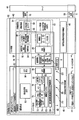
- FIG. 11 shows an application example to a warehouse management system called WMS (Warehouse Management System) as a usage scene of the present embodiment shown in FIG.
- WMS Warehouse Management System
- This WMS is broadly divided into a mechanism for solving two types of problems corresponding to “stock grasp” and “work support”.
- stock grasp grasp of the shelf life of inventory
- grasp of the storage position for each article in the warehouse grasp of the like can be mentioned.
- each image marker MK indicating the contents of the article is installed.
- the image marker MK a one-dimensional or two-dimensional code, or a mark (icon or the like) that can easily identify the contents of an article at a glance is described.
- the present invention is not limited to this, and each image marker MK may be a communication node with a built-in wireless communication function, or the image marker MK may have an arrangement information (position information) detection function using a beacon. .
- each rack (shelf) RK is selected / extracted (picked) by a worker (personal worker) PW (or measurement subject 2) and placed in a cart ( ⁇ ) CRT (or a large object). In the case of the transported object 8, it is put on the carriage 122).
- this worker PW wears the activity meter 4, and collects the detection raw signal from the activity meter 4 (1).
- the collected raw detection signals are temporarily stored in a memory unit (output waveform data storage unit from the sensor). Thereafter, the detection raw signal is read, and the processes (2) to (6) described above are performed.
- the result is used to improve the work of each worker PW (or the person 2 to be measured 2) (improvement of work action process and procedure).
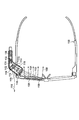
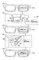
- a service such as the next action instruction is provided to the worker PW (or the person 2 to be measured) using the glasses-type wearable terminal (driving device) 1100 (see the detailed description using FIG. 38 and subsequent figures) ( 7) may be performed.
- the present embodiment is not limited to this, and the present embodiment may be applied to, for example, the social infrastructure market, the personal market, the healthcare market, the production / management market (design / manufacturing / inspection site), and the like.
- it may be used as a social infrastructure market, transportation environment or construction environment such as bridges and buildings, supply market of public consumer goods such as electricity, water and gas, financial industry market such as banking and securities / non-life insurance.
- public consumer goods such as electricity, water and gas
- financial industry market such as banking and securities / non-life insurance.
- you may use for a business use and application for each home.
- health care market it may be used at medical sites or nursing homes.
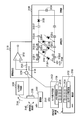
- the hardware configuration of the signal processing system in the present embodiment illustrated in FIG. 12 includes an activity meter 4, a sensor device 6, an edge device 42, and a server 40.
- the sensor device 6 is fixed to a predetermined object other than a person (for example, a carriage 122).
- a wired or wireless communication line is configured between the activity meter 4 and the edge device 42, between the sensor device 6 and the edge device 42, and between the edge device 42 and the server 40. Communication is possible.
- the edge device 42 and the server 40 cooperate to perform estimation result processing and service provision control, which will be described later.
- processing results contents of the transmission information 30
- the signal processing unit 60 inside the sensor device 6 are also collected.
- the functional configuration of the signal processing system shown in FIG. 12 includes an action estimation system 52, a service control unit 58, a position detection signal generation unit 46, and a control unit 48 thereof.
- the behavior estimation system 52 includes the activity meter 4, the sensor device 6, and a part of the edge device 42.
- the structure of the activity meter 4 is mainly described, but the hardware configuration 62 and the functional configuration 64 of the sensor device 6 basically match the structure of the activity meter 4.
- the activity meter 4 (and sensor device 6) includes a fixed member 50 and a signal detector 60.
- the fixing member 50 has a function of fixing the signal detection unit 60 to a part of the body of the measurement subject 2 when the measurement subject 2 is worn.
- the specific structure of the fixing member 50 has a wristband structure as shown in FIG. 1A and can be directly attached to the arm or foot of the person 2 to be measured.
- a structure that is attached to a human body using an adhesive layer, a part of a wearing part such as a hat, glasses, or shoes or a part of clothes (clothing) may be used.
- a part of a string used for packaging of the adhesive layer or the transported object 8 may be used as a structure of the fixing member 50 when the sensor device 6 is fixed to the transported object 8.
- the entire signal detector 60 is built in the activity meter 4 (or in the sensor device 6).
- the hardware configuration 62 of the signal detection unit 60 includes a power generation unit (environmental vibration type or photoelectric conversion type) 68 and a power storage unit (battery) 66, a triaxial acceleration sensor 72, a triaxial geomagnetic sensor 74, a signal amplifier group 76, A A / D converter (Analog to Digital Converter) 78, a control unit 80, a memory unit 82, and a communication control unit 84 are included.
- the power generation unit 68 As the form of the power generation unit 68, an environmental electric type described later may be used, or a photoelectric conversion type such as a solar cell may be used.
- the electric power generated by the power generation unit 68 is stored in the power storage unit 66. Then, each circuit of the signal detection unit 60 operates using the electric power stored in the power storage unit 66.
- the triaxial acceleration sensor 72 obtains acceleration signal waveforms (WX (t), WY (t), WZ (t)) in three axial directions (X-axis, Y-axis, and Z-axis directions) orthogonal to each other.
- the direction of geomagnetism can be detected using the triaxial geomagnetic sensor 74.
- the three-axis directions defined in the geomagnetic sensor 74 are also completely coincident with the three-axis directions (the X-axis, Y-axis, and Z-axis directions) of the three-axis acceleration sensor 72 described above. Yes. That is, in the signal detector 60 of the activity meter 4 and the signal detector 60 of the sensor device 6, three orthogonal directions (X axis, Y axis, and Z axis) are set in advance.
- a three-axis sensor for convenience of explanation, explanation will be made using an example of a three-axis sensor.
- the present invention is not limited to this.
- a 1-axis sensor or a 2-axis sensor may be used, or a further multi-axis sensor (for example, a 3-axis acceleration sensor function and a multi-axis angular velocity sensor function are built in the same sensor) may be used.
- a further multi-axis sensor for example, a 3-axis acceleration sensor function and a multi-axis angular velocity sensor function are built in the same sensor
- the detected raw signals (WX (t), WY (t), WZ (t)) in the three-axis directions obtained from the three-axis acceleration sensor 72 and the three-axis ground axis sensor 74 are individually amplified by the signal amplifier group 76. After that, it is converted into a digital signal by an A / D converter (Analog-to-Digital Converter) 78 and stored once in the memory unit 82.
- the signal detection unit 60 includes a control unit 80 and performs signal processing using the detection raw signals (WX (t), WY (t), WZ (t)) stored in the memory unit 82. . Further, the signal processing result is transmitted as transmission information 30 to the edge device 42 via the communication control unit 84.
- the detection raw signal is extracted from the triaxial acceleration sensor 72 and the triaxial geomagnetic sensor 74, and is converted into a digital signal by the A / D converter 78 through the signal amplifier group 76.
- the reference direction extraction 92 and the angle extraction 94 based on the result obtained by the detection raw signal generation 90 and the detection signal generation (signal processing) 96 after noise component reduction are performed by the control unit 80 while using the memory unit 82.
- the reference direction extraction 92 means a function of extracting a predetermined reference (direction) using the result of the detection raw signal generation 90.
- the gravitational direction for example, the z-axis direction
- the direction of geomagnetism for example, the y-axis direction
- a predetermined reference (the direction of the z axis or the y axis corresponding to the direction) and the coordinate axes (X axis and Y axis) set in advance in the activity meter 4 or the sensor device 6 are used.
- the process of calculating the angle ⁇ between the axis and the Z axis corresponds to the angle extraction 94 described above.
- the detection signal generation (signal processing) 96 after noise component reduction is a signal processing of the detection raw signals (WX (t), WY (t), WZ (t)) using the result of the angle extraction 94.
- it means a function of generating detection signals (Wx (t), Wy (t), Wz (t)) after noise component reduction.
- At least one of the detection signals (Wx (t), Wy (t), Wz (t)) obtained as a result is a detection raw signal (WX (t), WY (t), WZ (t)).
- the noise component is further reduced.
- the result is transmitted from the activity meter 4 to the edge device 42 via the communication control unit 84.
- the transmission information 30 transmitted at this time includes extraction angle information 32 and detection signal information 34 after noise component reduction.
- the system of this embodiment shown in FIG. 12 has a communication control unit 84 built in both the activity meter 4 and the sensor device 6, and each has a wireless communication function. Using this wireless communication function, the user's position may be detected by a method similar to GPS (Global Positioning System).
- GPS Global Positioning System
- the position detection signal transmitters 46 controlled by the position detection signal generation controller 48 of the edge device 42 are distributed in different locations from (A) to (D). From each of the points (A) to (D), transmission time information is continuously transmitted wirelessly. Further, a time difference received by the communication control unit 84 of time information transmitted from each of the points (A) to (D) is detected, and the active meter 4 (or sensor device 6) is arranged in real time using trigonometry. The location can be detected.
- the behavior estimation engine 56 of the behavior estimation unit 54 owned by the edge device 42 performs behavior estimation (or state estimation or request estimation of the measurement subject 2) based on the transmission information 30 transmitted from the sensor devices 4 and 6. Based on the estimation result, the service control unit 58 proposes service provision and business improvement 10.
- the content of the service instruction 11 is returned from the server 40.
- the driving device 44 is operated from the edge device 42 using wireless communication, and the service is provided to the measurement subject 2 or other users.
- the drive device 44 incorporates an electric motor, a light emitting element, a display element, a speaker, and the like, and performs driving, light emission, display, audio output, and the like of the electric motor according to an operation from the edge device 42.
- FIG. 13 shows another embodiment system relating to the signal processing system shown in FIG.
- the embodiment system (signal processing system) of FIG. 13 only the detection raw signal generation 90 and the position detection 98 are performed in the activity meter 4 (or in the sensor device 6) in the functional configuration 64 that the position detection unit 60 assumes. Executed.
- the detected position information 38 and the detected raw signal information 36 are transmitted as the activity information 4 or sensor device. 6 to the edge device 42.
- the edge controller 42 is particularly specified with the communication control unit 86, the control unit 81, and the memory unit 83 included in a part of the hardware configuration 62 of the signal detection unit 60.
- the communication device 86, the controller 81, and the memory unit 83 exist in the edge device 42 even in the signal processing system form shown in FIG. 12.
- the detected position information 38 and the detected raw signal information 36 transmitted from the activity meter 4 (or the sensor device 6) are transmitted via the communication control unit 86.
- the control unit 81 of the edge device 42 performs signal processing using the detection raw signals (WX (t), WY (t), WZ (t)) stored in the memory unit 83.
- the detection signals (Wx (t), Wy (t), Wz (t)) after noise component reduction obtained as a result of this signal processing are also stored in the memory unit 83.
- the signal processing is performed on the detection raw signals (WX (t), WY (t), WZ (t)) collected from the triaxial acceleration sensor 72 and the triaxial geomagnetic sensor 74 by the edge device 42.
- the functions of the meter 4 and the sensor device 6 can be simplified. As a result, there is an effect that the entire signal processing system as well as the active mass meter 4 and the sensor device 6 can be made inexpensive.
- the behavior estimation engine 56 built in the behavior estimation unit 54 of the edge device 42 detects the detection signal (Wx (t), Wy (t), Wz (t)) after the noise component reduction stored in the memory unit 83. Is used to perform the action estimation process or state estimation process of the measurement target person 2 and the request estimation process (of the measurement target person 2 or other users).
- the hardware configuration 63 for executing the processing of the behavior estimation unit 54 at this time is the content of the hardware configuration 62 belonging to the signal detection unit 60 installed in the edge device 42 (communication control unit 86 and control unit 81, memory unit 83). Is also used.
- the behavior estimation result 16 performed by the behavior estimation engine 56 of the behavior estimation unit 54 owned by the edge device is transmitted to the server 40.
- the server 40 examines the service provision contents using the result. Thereafter, the service instruction 11 is issued from the server 40 to the edge device 42.
- the direction from the arm 120 of the measurement subject 2 wearing the activity meter 4 toward the middle finger is set as the Y axis.
- the action direction 100 (the direction in which the measurement subject 2 exerts a force) when the measurement subject 2 pushes the carriage is matched with the Y-axis direction.
- the direction perpendicular to the back of the measurement subject's hand is set as the Z-axis direction
- the direction perpendicular to the Y-axis and the Z-axis (the direction from the little finger of the measurement target 2 toward the thumb) is set as the X-axis.
- acceleration waveforms detected raw signals WX (t), WY (t), WZ (t)
- the Y-axis direction, and the Z-axis direction are obtained from the triaxial acceleration sensor 72. .
- the magnetic field intensity signals in the X-axis, Y-axis, and Z-axis directions may be described from the triaxial geomagnetic sensor 74.
- WX * (t), WY * (t), or WZ * (t) may be described).
- a direction along the reference A (geomagnetic direction) 102 is defined as a y-axis (a direction from the south pole direction 114 toward the north pole direction 112).
- the direction from the west direction to the east direction is defined as the x-axis.
- the waveforms of Wx (t) and Wy (t) are not directly detected as detection raw signals.
- the direction in which the measurement subject 2 pushes the carriage 122 (the action direction 100 of the Y axis) has an inclination of ⁇ yz with respect to the plane 118 perpendicular to gravity.
- the inclination angle between the z-axis and the Z-axis is also ⁇ yz.
- the time change of the virtual acceleration waveform Wy (t) to be obtained in the y-axis direction is shown on the right side of FIG.
- the Wy (t) waveform increases with time as the carriage 122 starts moving. To do.
- the time change of the virtual acceleration waveform to be obtained in the gravity direction (z-axis direction) at this time is represented by Wz (t). Since a constant gravitational acceleration always acts on the activity meter 4, a DC component corresponding to the gravitational acceleration G is always added to Wz (t).
- Neither the Wy (t) waveform nor the Wy (t) waveform shown on the right side of FIG. 15 can be directly collected as a detection raw signal from the triaxial acceleration sensor 72 (or triaxial geomagnetic sensor 74). However, if the angle ⁇ yz is used, the detection raw signals WZ (t) and WY (t) that can be directly collected by the triaxial acceleration sensor 72 (or triaxial geomagnetic sensor 74) are converted into Wz (t) and Wy (t). It can be calculated.
- reference is made using detection raw signals WX (t), WY (t), and WZ (t) obtained from various sensors of the sensor device (activity meter) 4 and the sensor device 6.
- a (geomagnetic direction) 102 and reference B (gravity direction) 104 are extracted.
- FIG. 16 shows an application example for FIG.
- signal processing using the detection raw signal from the activity meter 4 attached to the arm 120 of the measurement subject 2 / behavior estimation of the measurement subject 2 is performed, and the work improvement is performed through the behavior history analysis of the measurement subject 2. (Work process improvement) and provide necessary services.
- the behavior estimation of the measurement subject 2 is not limited thereto, and for example, the sensor device 6 is fixed to a part of a predetermined object such as the carriage 122 (by pasting or the like), and the signal from the detected raw signal alone collected from the sensor device 6 Processing / Behavior estimation ⁇ Behavior history / Business improvement and service provision may be performed.
- the detection raw signal from the activity meter 4 and the detection raw signal from the sensor device 6 may be combined. Combining both increases the estimation of the behavior of the measurement subject 2 and produces an effect that enables more appropriate business improvement planning and service provision.
- the edge device 42 can operate the drive device 44 to provide a service (to the measurement subject 2 or other users).
- an electric motor (drive device) 124 corresponding to a kind of the drive device 44 and a light emitting element or speaker (drive device) 126 are provided.
- the electric motor 124 moves based on the service instruction 11 from the server 40 determined that “the measurement subject 2 is moving on the carriage 20”. Light emission from the light emitting element or audio output from the speaker is performed. Since the electric motor 124 automatically starts during the movement of the trolley 2 of the measurement subject 2, an effect of reducing the burden on the movement of the trolley for the measurement subject 2 is produced. In addition, “warning” to a third party accompanying the movement of the carriage can be automatically performed by the light emission of the light emitting element or the sound output from the speaker. As a result, there is also an effect that enables the carriage to move safely (preventing inadvertent contact with a third party).
- the weak signals obtained from the various sensors 72 and 74 are amplified in the signal amplification group 76 inside the signal detection unit 60, and converted into digital signals through the A / D converter 78.
- a method for generating a signal component in a predetermined direction from the detected raw signals WZ (t), WY (t), WX (t) from the various sensors 72 and 74 using the angle ⁇ extracted by the above method will be described below. .
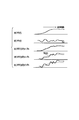
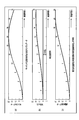
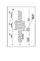
- FIG. 17 shows the change over time of the detection signal obtained directly or indirectly when the subject 2 pushes the stationary carriage 122 and the carriage 122 starts to move.
- the coordinate axes are the same as in FIG. 16 (when the X axis and the x axis coincide).
- the acceleration waveform Wy (t) in the movement direction (y-axis direction) of the carriage increases with time as shown in FIG.
- the acceleration waveform Wz (t) in the gravitational direction (z-axis direction) is added to the gravitational acceleration component G (DC component) that always exists, and an acceleration change corresponding to the uneven shape of the floor 128 appears. (FIG. 17B).
- the Y-axis direction set in advance in the activity meter 4 is inclined by the angle ⁇ yz with respect to the plane 118 perpendicular to gravity. Therefore, a noise component of Wz (t) (corresponding to the uneven shape of the floor surface 128) is mixed into the detection raw signal WY (t) according to the angle ⁇ yz.
- the ⁇ yz when the measurement subject 2 having a standard height pushes the carriage 122 is represented by ⁇ s.
- some signal processing is performed on the detection raw signal shown in FIG. 17C or 17E to reduce the influence of the height of the person 2 to be measured.
- the accuracy of determining the behavior estimation (or situation estimation) is improved. Occurs.
- the detection raw signal shown in FIG. 17C or FIG. 17E is converted into a detection signal “WY (t)
- the behavior estimation is performed by matching the waveform (correct waveform) that is the basis of the behavior estimation with the actual waveform.
- the waveform corrected waveform
- DP matching matching method based on dynamic programming
- FIG. 18A An example of a standard measurement acceleration waveform (sample data) measured in advance is shown in FIG.
- the acceleration in the movement direction (y-axis direction) of the trolley 122 increases from “0” with the passage of time.
- the detected acceleration decreases (FIG. 18A).
- the horizontal axis memory in FIG. 18 represents a cycle period (for example, 50 mS). Values for convenience of the standard measurement acceleration waveform (sample data) collected for each cycle period are clearly shown in each graph of FIG.
- FIG. 18B shows the detection raw signal WY (t) in the Y-axis direction when the action speed (work speed) when the measurement subject 2 this time starts to push the carriage 122 is slower than the “standard speed”.
- the low-frequency component (DC component) of Q42L caused by gravity is always superimposed on the detection raw signal WY (t) in the Y-axis direction.
- the measurement subject 2 compared with the standard measurement acceleration waveform (sample data) (FIG. 18A), the measurement subject 2 slowly pushed the carriage 122 this time. Therefore, the amount of acceleration change in FIG. 18B is smaller in FIG. 18B than the standard measurement acceleration waveform (sample data).
- FIG. 18C shows the characteristic after the amplitude value is normalized so that the resultant amplitude value matches that shown in FIG.
- the maximum signal amplitude matches the standard measurement acceleration waveform (sample data) of FIG. 18 (a). However, since the measurement subject 2 slowly pushes the carriage 122, the degree of signal change in the time axis direction is small (slow).
- the expansion / contraction matching method employed in the system of the present embodiment automatically corrects the difference in expansion / contraction in the time axis direction between FIG. 18 (a) and FIG. 18 (c).
- the degree of coincidence can be calculated. Therefore, pattern matching can be performed while correcting the difference in the action speed of the measurement subject 2 or the difference in the processing speed corresponding to the fixed object obtained by the sensor device 6, so that it is accurate regardless of variations in the action speed (processing speed). There is an effect that pattern matching determination can be performed.
- the waveform of FIG. 18C is transcribed in the horizontal axis direction of FIG. 19, and the waveform of FIG. 18A is transcribed in the vertical axis direction of FIG.
- the pattern amplitude in the horizontal axis direction matches the pattern amplitude in the vertical axis direction.
- the connection (arrow) between intersections having similar amplitude values is regarded as the optimum route, and the optimum route is sequentially searched. To do.
- This optimum route search is a process for absorbing variation in action speed (processing speed).
- the “enlarged area” shown in FIG. 19 is enlarged and shown in FIG.
- the amplitude change in the horizontal axis direction changes from “7” to “11” when the elapsed time advances by the cycle period, whereas the amplitude in the vertical axis direction changes from “8” to “13”.
- the value of the square of the deviation from the sample data after passing through the path (1) is calculated.
- the amplitude value in the vertical axis direction after passing through the path (1) remains “8” and does not change.
- the amplitude value in the horizontal axis direction changes from “7” to “11”.
- the route with the smallest square value of the deviation amount after passing the route is automatically selected. Therefore, in the example shown in FIG. 20, the route (2) having “4” having the smallest square value of the deviation amount is automatically selected. As a result of automatically selecting the optimum route in this way, it is possible to match patterns whose expansion and contraction in the time axis direction changes as in the relationship between FIGS. 18A and 18C.
- sample data When there are multiple candidates for behavior estimation of the person to be measured 2 (multiple types of standard measurement acceleration waveforms (sample data) are prepared), the standard measurement after conversion for each different standard measurement acceleration waveform (sample data) The Euclidean distance between the acceleration and the acceleration is calculated, and it is determined that the behavior of the measurement subject 2 is similar to the behavior estimation candidate with the smallest Euclidean distance.
- FIG. 21 shows another embodiment in which the behavior estimation system 52 described above with reference to FIGS. 12 and 13 is realized with another hardware configuration.
- the behavior estimation system 52 includes a signal detection unit 60 and a behavior estimation unit 54.
- a memory unit (output waveform data storage unit) 82, an output waveform data / acceleration extraction unit 160, an angle extraction unit 164, a coordinate conversion unit 166, a filter unit 162, and a control unit (control management unit) ) 80 is included in the signal detection unit 60.
- the behavior estimation unit 54 includes a storage unit 170 for standard measurement target person data (sample data to be a target for matching comparison), a feedback data data storage unit 176, a feedback data processing unit 178, a threshold value change determination unit 182, The threshold value changing unit 184, the operation determining unit 172, the operation determining threshold storage unit 174, and a part of the control unit (control management unit) 80 are included.
- the memory unit (output waveform data storage unit) 82 stores data (detected raw signal) measured from the activity amount form 4.
- the memory unit (output waveform data storage unit) 82 corresponds to the memory unit 82 of FIG. 12 or FIG.
- the output waveform data / acceleration extraction unit 160 performs the function of the detection raw signal generation 90 of FIG. 12 or FIG.
- the specific hardware structure related to the output waveform data / acceleration extraction unit 160 corresponds to the triaxial acceleration sensor 72, the signal amplifier group 76, and the A / D converter 78 shown in FIG.
- the function of the filter unit 162 coincides with the function of the low-pass filter process 138 described with reference to FIG. That is, the filter unit 162 extracts the gravitational acceleration components Q41L, Q42L, and Q43L from the acceleration value output from the output waveform data / acceleration extraction unit 160.
- the low-pass filter characteristics of the prior art may be used, but not limited thereto, for example, a filtering method for obtaining an average value may be used. 21.
- the function of combining the angle extraction unit 164 and the filter unit 162 in FIG. 21 corresponds to the reference direction extraction 92 and the angle extraction 94 in FIG. That is, the angle extraction unit 164 calculates the angle ⁇ yz (see FIG.
- this angle extraction uses the gravitational component and the trigonometric function included in the acceleration value measured by the wristband type activity meter (sensor device) 4 attached to the arm 120 of the measurement subject, to determine the angle ⁇ yz. Perform the calculation.
- the coordinate conversion unit 166 has a function of detection signal generation (signal processing) 96 after noise component reduction in FIG. 12 or FIG. That is, the standard measurement after conversion using the equation (5) or (7) from the measured acceleration waveform (detected raw signal) WX (t), WY (t), WZ (t) acquired from the triaxial acceleration sensor 72 Rotational conversion (signal processing) into acceleration is performed here. At this time, the angle d ⁇ yz calculated from the angle extraction unit 164 using the gravity value is used.
- the standard measurement acceleration waveform (sample data) is stored in the storage unit 170 of the standard measurement target person data (sample data to be subjected to matching comparison).
- the next feedback data storage unit 176 stores data output by a feedback data processing unit described later.
- the error characteristic (or standard measurement acceleration waveform (sample data) between the standard measurement acceleration after conversion with respect to the angle ⁇ ( ⁇ yz) of the arm 120 of the measurement subject 2 and the measurement acceleration waveform (detected raw signal).
- the Euclidean distance characteristic was explained. This characteristic is stored in the feedback data storage unit 176.
- the operation determination unit 172 determines whether or not the action of the measurement subject 2 at the measurement target time has made the carriage move 20.
- the characteristics shown in FIG. 8 are used for this determination, and information on the determination threshold 150 when estimating the behavior of the measurement subject is used as the determination criterion.
- the information of the determination threshold value 150 at the time of estimating the behavior of the measurement subject is stored in the action determination threshold value storage unit 174.
- the error amount between the standard measurement acceleration after conversion with respect to the angle ⁇ yz of the arm 120 of the measurement subject 2 and the measurement acceleration waveform (detected raw signal) or the standard measurement acceleration waveform (sample data) and The compared Euclidean distance is appropriately calculated in real time for each cycle. Then, the threshold change determination unit 182 monitors in real time (for each cycle) whether or not the error amount or the Euclidean distance has exceeded the determination threshold 150 when the measurement subject's behavior is estimated. If the error amount or the Euclidean distance exceeds the determination threshold 150, information is transmitted to the threshold change determination unit 182 to change the determination threshold 150.
- the threshold value changing unit 184 performs change control of the determination threshold value 150 when estimating the behavior of the measurement subject based on the transmission information from the threshold value change determining unit 182.
- the method of rotation conversion explained in detail.
- the data stored in the memory unit (output waveform data storage unit) 82 is read out from the date of collecting the behavior data of the measurement subject 2 (at a later date), and the processing until the behavior estimation of the measurement subject 2 or ( A series of processes leading to the work improvement (work process improvement) in 6) may be performed together (batch processing).
- control unit 80 reads the detection raw signals WX (t), WY (t), and WZ (t) from the memory unit (output waveform data storage unit) 82, and the angle extraction unit 164. Forward to.
- the angle extraction unit 164 incorporates the function of the low-pass filter processing 138 described in FIG. 3, and calculates the values of Q41L, Q42L, and Q43L. Next, ⁇ yz and the like are calculated using equations (1) to (3) obtained from FIG. 2, and then d ⁇ yz and the like are calculated.
- the detection raw signals WX (t), WY (t), WZ are obtained by using the equation (5) obtained from FIG. 4 or the equation (7) obtained from FIG. 4, FIG. 9, and FIG. (T) is rotationally converted (signal processing), and standard measurement accelerations WXs (t), WYs (t), and WZs (t) after conversion are calculated.
- the method (A) to (C) (or a combination thereof) has already been described as a method for estimating the behavior of the measurement subject 2.
- (A) dispersion between detection signals before and after rotation conversion (signal processing) and irregularity determination are used for behavior estimation will be described.
- the feedback data processing unit 178 extracts the relationship between the error amounts between WZ (t) and the standard measurement accelerations WXs (t), WYs (t), and WZs (t) after rotational coordinate conversion. The extraction result is recorded in the feedback data storage unit 176.
- the data to be recorded in the feedback data storage unit 176 is the data of the measurement subject 2 measured the previous day for two or three hours of continuous data or one day of data at a time. Can be recorded together.
- the feedback data processing unit 178 statistically analyzes the data recorded in the feedback data storage unit 176, and the characteristics shown in FIG. Create a graph.
- the determination threshold value 150 at the time of the measurement target person behavior estimation is a constant value regardless of the angle ⁇ .
- the present invention is not limited to this, and the determination threshold 150 may be reset as appropriate according to the angle ⁇ .
- the threshold value change unit 184 sets the changed threshold value. Then, the changed threshold value corresponding to the reset angle ⁇ is appropriately stored in the action determination threshold value storage unit 174.
- the threshold value change determination unit 182 determines whether or not the threshold value change unit 184 needs to reset the threshold value. When the threshold needs to be reset, the information is transmitted from the threshold change determination unit 182 to the threshold change unit 184.
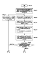
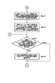
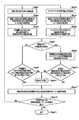
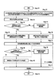
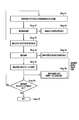
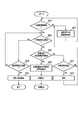
- FIG. 21 Another embodiment relating to the processing flow performed by the behavior estimation system 52 shown in FIG. 21 will be described with reference to FIGS. 22A to 22C.
- Step A1 the measurement object 140 of standard height measures acceleration waveform data obtained by moving the carriage 122, and the standard measurement object data (sample to be subjected to matching comparison). Data) is stored as a standard measurement acceleration waveform (sample data).
- Step A2 the output waveform data / acceleration extraction unit 160 acquires a detection raw signal (measurement acceleration waveform (detection raw signal)) from the measurement subject 2.
- Step B1 the filter unit 162 extracts the decomposition component of gravity acceleration (G41L and G42L). (See FIG. 3).
- Step B2 the angle extraction unit 164 calculates the tilt angle ⁇ ( ⁇ yz) of the arm 120 of the measurement subject 2 from the acquired Q41L and Q42L.
- formula (1), formula (2), or formula (3) obtained using FIG. 2 is used.
- setting 1 method of calculating ⁇ ( ⁇ yz) using equation (1)”
- setting 2 ⁇ ( ⁇ yz) using equation (2)
- setting 3 a method of calculating ⁇ ( ⁇ yz) using equation (3)” may be used.
- the present invention is not limited to this, and “setting 4: a method of using an average value between ⁇ ( ⁇ yz) values obtained by equations (1) and (2)” may be used. Furthermore, “Setting 5: Method of using the average of all values of ⁇ ( ⁇ yz) obtained by the equations (1), (2), and (3)” may be used.
- Step B3 the coordinate conversion unit 166 performs rotation conversion (signal processing) from the measured acceleration waveform (detected raw signal) WX (t), WY (t), WZ (t) to the converted standard measured acceleration.
- the above-described equation (5) or (7) is used for this rotation conversion (signal processing).
- Step A2 to Step B3 in FIG. 22A there is a relationship of “behavior estimation determination period” ⁇ “statistical processing accumulation period” ⁇ “cycle period”.
- one processing flow from Step A2 to Step B3 in FIG. 22A means one cycle of processing. Therefore, in order to perform the behavior estimation of the measurement subject 2 by the behavior estimation system 52, it is necessary to repeat the cycle at least the number of times corresponding to the “behavior estimation determination period” at least (for example, the “behavior estimation determination period”).
- “is 4 seconds and“ cycle period ” is 50 ms, it is necessary to repeat the processing flow from Step A2 to Step B3 at least 80 times at first).
- Step B5 it is determined whether or not the above cycle has been repeated a predetermined number of times. If the predetermined number of times has not been reached, the output waveform data / acceleration extraction unit 160 advances (increments) one cycle and starts the next processing flow (cycle) from Step A2 to Step B3 (Step B10). On the other hand, if the behavior estimation process can be executed after the cycle has already been repeated a predetermined number of times, the process proceeds to Step B4.
- the error between the measured acceleration waveform (detected raw signal) and the converted standard measured acceleration is the threshold condition.
- the operation determination unit 172 determines whether or not the user is satisfied.
- the dispersion and irregularity determination between detection signals before and after the above-described (A) rotation transformation (signal processing) (B) Determination of similarity between standard measurement acceleration after conversion and sample data (C) One or a combination of expansion / contraction matching determination between standard measurement acceleration after conversion and sample data may be performed.
- Step B7 If the threshold condition is not satisfied as the determination result of the above behavior estimation, it is determined that the measurement target person 2 has not moved the carriage 122 at the target time from the operation determination unit 172 (Step B7).
- Step B8 determines and outputs that the carriage is moving at the target time.
- the edge device 42 and the server 40 cooperate with each other as needed to improve the service based on the service provision and the measurement target person 2 action history. 10 proposals are made (FIGS. 1, 11 to 13).
- Step A2 The processing from Step A2 to Step B7 / B8 is repeated until the behavior estimation processing or service provision processing is completed. That is, in Step B9, it is determined whether or not all corresponding sections of the measurement data have been processed.
- Step E the series of processes is terminated (Step E).
- the process returns to Step A2 via Step B10.
- the determination threshold 150 at the time of estimating the behavior of the measurement subject as described with reference to FIG. 8 is appropriately changed (FIG. 22C).
- the feedback data processing unit 178 the measurement acceleration waveform (detected raw signal) with respect to the angle ⁇ ( ⁇ yz) of the arm 120 of the measurement subject 2 shown in FIG. A characteristic of an error amount with respect to acceleration (or a Euclidean distance calculated by comparison with a standard measurement acceleration waveform (sample data)) is determined. The result is recorded in the feedback data storage unit 176 (Step C1).
- the feedback data processing unit 178 reads the above characteristic data from the feedback data storage unit 176, performs statistical processing for each angle ⁇ ( ⁇ yz), and based on the result, the determination value 150 at the time of the action estimation unit for the measurement subject. A correction value of (matching threshold) is calculated. The correction value calculated there is stored in the feedback data storage unit 176 (Step C2).
- Step C3 The result is read from the feedback data storage unit 176, and the threshold value change determination unit 182 determines whether or not the angle error for each angle ⁇ ( ⁇ yz) exceeds a set value (for example, 15%) (Step C3). Here, if it does not exceed, the process after Step B4 is continued without performing a specific process.
- Step C3 determination result If the value exceeds the set value (Step C3 determination result), the threshold value is changed by changing the correction of the threshold value used for matching determination according to the extracted angle ⁇ ( ⁇ yz). This is performed by the unit 184 (Step C4).
- FIGS. 22A to 22C are examples of behavior estimation when the measurement subject 2 moves the carriage 20.
- the present embodiment system (behavior estimation system 52) is not limited to the cart 20 of the person to be measured 2 but can be applied to behaviour estimation for all other actions.
- the sensor device 6 is not limited to the specific measurement subject 2 and is obtained from the sensor device 6 fixed to a predetermined object (FIG. 25A) such as a part of the carriage 122 or the transported object 8 as shown in FIG. You may perform state estimation (estimation with respect to the state of a predetermined object) using a detection signal.
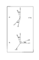
- the method of taking the angle ⁇ yz in FIGS. 2 and 15 is based on the coordinate axes (Y axis and Z axis) preset in the wristband type activity meter (sensor device) 4 as a reference line. Then, the angle ⁇ yz is set in the counterclockwise direction with respect to the rotation angle from the reference line (Y axis and Z axis).
- the present invention is not limited to this, and the angle ⁇ yz ′ may be set in the clockwise direction as shown in FIGS. 23 and 24. Similarly, the angle ⁇ yz ′ may be set in the counterclockwise direction by taking the z-axis or y-axis along the gravity direction or the floor surface direction as a reference line.
- FIG. 25A shows an example of a state estimation method when the measurement subject 2 transports the transported object 8 by directly holding it in the hand without using the carriage 122.
- the coordinate axis directions similar to those in FIGS. 14, 15, and 16 are defined. That is, in the wristband type activity meter (sensor device) 4 worn by the measurement subject 2, the direction from the measurement subject's arm 120 to the finger is the Y axis, and the direction perpendicular to the direction from the little finger of the left hand to the thumb X The axis direction perpendicular to the axis and back of the hand is defined as the Z axis.
- the direction of the reference B (gravity) 104 is defined as the z-axis
- the direction of the reference A (geomagnetic direction) 102 is defined as the y-axis.
- the reference B (gravity) 104 and the reference are obtained from the detected raw signals collected from the triaxial acceleration sensor 72 and the triaxial geomagnetic sensor 74 built in the wristband type activity meter (sensor device) 4.
- a (geomagnetic direction) 102 is extracted.
- the x-axis direction and the X-axis direction are temporarily matched.
- the Y-axis direction approaches the z-axis direction.
- the Y axis is oriented in the direction perpendicular to the z axis. Therefore, only by examining the relationship between the x-axis of the Y-axis, the y-axis, and the z-axis, it can be inferred whether the measurement subject 2 is in the empty state or has a specific transported object 8. Therefore, in this application example, first, the Y-axis direction is examined.
- the disturbance noise component Wz (t) accompanying the vertical movement of the transported object 8 appears most greatly in the detection raw signal WX (t) collected from the triaxial acceleration sensor 72. Therefore, the disturbance noise component mixed in WX (t) and WY (t) can be reduced by using the disturbance noise component Wz (t) appearing in WX (t).
- a plurality of detection raw signals that change with time are collected from one or a plurality of sensors, and signal processing across a plurality (or a part) of detection raw signals is performed.
- Noise reduction and extraction of specific signal components As an example of the extraction of the specific signal component, the example of the extraction method of the predetermined reference has been described using the equations (1) to (3) from the predetermined frequency components Q41L, Q42L, and Q43L obtained after the low-pass filter processing 138 in FIG. .
- the present invention is not limited thereto, and the specific signal component may be extracted using any other processing method. Further, as an example of signal processing performed at this time, processing using the formula (4) or (6) shown in FIG. 25C may be performed.
- the present invention is not limited to this, and any other signal processing method such as a vector operation shown in FIG.
- the detection raw signals collected from the triaxial acceleration sensor 72 of FIG. 12 or FIG. 13 and the position detection function 98 may be combined. That is, the relative position of the wristband type activity meter (sensor device) 4 can be estimated by performing signal processing (signal calculation) on the detection raw signal collected from the triaxial acceleration sensor 72. The position detection accuracy of the wristband type activity meter (sensor device) 4 is improved by feeding back the result of the position detection function 98 described above to this estimation result.
- FIG. 26 shows a method for improving the detection accuracy by combining the detected raw signal.
- the sensor device 6 also includes the triaxial acceleration sensor 72 and the triaxial geomagnetic sensor 74 and a position detection function 98 using the communication control unit 84.
- the direction of gravity (reference B) 104 is extracted in parallel in the wristband activity meter (sensor device) 4 (Step 1) and in the sensor device 6 (Step 2).
- the sensor device 6 may be fixed to a part of the carriage 122 as shown in FIG. 16, or may be directly fixed to the object 8 itself along FIG.
- Step 3 With respect to the detected raw signal in parallel in the wristband type activity meter (sensor device) 4 (Step 3) and in the sensor device 6 (Step 4) based on the angle ⁇ yz of the extracted gravity direction (reference B) 104, respectively. Perform signal processing to reduce noise components.
- the behavior estimation engine 56 of the edge device 42 based on the result of the noise component reduction described above is performed for the wristband activity meter (sensor device) 4 (Step 5) and for the sensor device 6 (Step 6). Each conducts a behavior estimation decision.
- Step 7 it is determined whether a highly accurate behavior estimation is necessary. If highly accurate behavior estimation is not required, only the behavior estimation result based on the data obtained only from the wristband type activity meter (sensor device) 4 is used (Step 8), and the measurement subject 2 Business improvement proposals and service provisions (Step 11) or termination processing (Step 14) based on the behavior history for each are performed.
- Step 7 when a highly accurate behavior estimation is required as the determination result of Step 7, the behavior estimation determination result from the wristband activity meter (sensor device) 4 and the behavior estimation determination result from the sensor device 6 are combined (Step 9). ).
- Step 9 selection of business improvement proposal or service provision (Step 11) or termination processing (Step 14) based on the action history for each measurement subject 2 is performed.
- Step 13 the process from Step 1 / Step 2 to Step 11 with one cycle period as a cycle is repeated until the action estimation process or the service provision process is completed. Then, in step 12, it is determined whether or not the process is repeated.
- the series of processes ends (Step 13).
- the present embodiment system (behavior estimation system) is not limited thereto, and the state of the target object may be estimated from the detected raw signal collected from a predetermined object (other than a person or an animal), and the service may be provided accordingly.
- the direction of the Z axis set in the triaxial acceleration sensor 72 is relative to the z axis along the reference B (gravity) 104. Lean. Then, the roll component 208 in the y-axis direction generated when the elevator chamber 202 moves up and down in the z-axis direction is mixed as a noise component with respect to the detection raw signals WZ (t) and WY (t).
- the components Q41L and Q42L are extracted using the low-pass filter processing 138 (FIG. 3), and the mounting inclination angle ⁇ yz of the triaxial acceleration sensor 72 can be calculated using the equation (1).
- each detection signal of Wy (t) corresponding to the roll component 208 and Wz (t) representing only the vertical movement of the elevator chamber 202 (mixing amount of the roll component 208 is reduced) is represented. To separate.
- the estimation engine 56 of the edge device 42 determines whether or not the elevator chamber 202 is moving up and down as planned. If a detection signal Wz (t) different from the schedule is obtained during vertical movement, it is considered that the elevator is out of order and the elevator repair service is provided.
- the state of the roll 208 generated when the elevator chamber 202 moves up and down is monitored by the estimation engine 56 of the edge device 42 from the detection signal Wy (t). If an abnormal roll is detected when the elevator chamber 202 moves up and down, an elevator repair service is provided.
- FIG. 28 shows an application example in which this embodiment is applied to a bus, a truck, and a passenger car 210.
- the reference B (gravity direction) 104 is extracted from the detection raw signals WX (t), WY (t), and WZ (t) collected from the three-axis acceleration sensor 72 fixed in the bus, the truck, or the passenger car 210, and based on it.
- the vertical vibration of the bus or truck, the passenger car 210 It is possible to detect the state of acceleration, deceleration, and course change in the left-right direction.
- the acceleration / deceleration direction of the bus, truck, or passenger car 210 indicates the y-axis direction, and the z-axis direction coincides with the gravity direction 104 corresponding to the reference B.
- the direction in which the bus, the truck, and the passenger car 210 turn sideways faces the x-axis direction.
- the history of the steering wheel operation during driving may be extracted by fixing the triaxial angular velocity sensor 212 to the steering wheel 214 of the bus, truck, or passenger car 210 via the fixing member 50 (adhesive or the like).
- the fixing member 50 adheresive or the like.
- vertical movement vibration, acceleration, deceleration, and left-right direction change of the bus or truck and the passenger car 210 are mixed as disturbance noise.
- the detection raw signal obtained from the triaxial acceleration sensor 72 may be used to perform signal processing on the detection raw signal from the triaxial angular velocity sensor 212 to reduce the disturbance noise component.
- the operation history of the handle 214 can be detected with high accuracy, and the driver's behavior estimation and the driver can be detected. Or the effect that the appropriate service to a passenger can be provided is born.
- a predetermined specified route direction for example, a slope direction of a slope
- the reference C specified route
- the floor surface 128 needs to face a direction perpendicular to the direction of gravity.
- the direction along the slope is set as a new reference C ( If it is set as (regulated route) 106, the measurement target person 2 is more efficient in estimating the behavior.
- a direction along the slope (direction in which the measurement subject 2 moves) with respect to the floor surface 128 having a plane perpendicular to the gravitational direction 104 is defined as a new reference C (regulated route) 106, and the direction. Is defined as the u axis, and the direction perpendicular to the u axis (the direction along the slope 220) is defined as the w axis.
- the movement routes of the plurality of measurement subjects 2 are integrated, and the reference C (specified route) is based on the statistical processing result.
- the position detection signal generators 46 (A) to (C) are arranged in advance within the range in which the measurement subject 2 moves.
- the position detection signal generators 46 (A) to 46 (C) continuously transmit time information at the time of transmission using wireless communication.
- the communication control unit 84 of the wristband type activity meter (sensor device) 4 receives the time information at the time of transmission, detects a time lag with respect to the time of reception, and uses the trigonometry to determine the communication control unit 84. The position information of is detected.
- the history information regarding the position change of the wristband type activity meter (sensor device) 4 is accumulated (in the memory unit 82 in FIG. 12 and FIG. 13).
- a reference C (specified route) 106 can be extracted from the history information.
- FIG. 29A the history information about the movement route when the measurement subject 2 climbs the hill 220 and pushes the carriage 122 is used.
- the present invention is not limited to this, and as shown in FIG. 29B, the movement path history when the measurement subjects 2-1 to 2-3 wearing the wristband type activity meter (sensor device) 4 move on the slope 220 in the empty-handed state. May also be used.
- the reference C (regulated route) 106 is extracted using the history of position changes during movement of the N measurement subject 2.
- Step 25 After completing a series of data collection, statistical analysis of the movement paths of N measurement subjects is performed (Step 25). Using the result, in Step 26, the entry prohibition area of the measurement subject is extracted. As shown in FIGS. 29A and 29B, the person 2 to be measured who climbs the slope 220 cannot pass under the slope (a position below the floor 128). Accordingly, the lower side of the slope 220 shown in FIGS. 29A and 29B (in the ground of the slope) is the entry prohibition area. The inclination angle ⁇ of the slope 220 is calculated using the entry prohibition area information of the measurement subject thus calculated (Step 27).
- the standard route (standard C (standard route) 106) serving as a reference is calculated from the past history information that the measurement subject 2 has passed (Step 28).
- FIG. 30 shows a usage example of a photoelectric conversion signal obtained from an optical sensor.
- the sunshine direction may be set to the reference D_108.
- the reference D (sunshine direction) 108 can be extracted using sunlight from the sun 230.
- FIG. 30 shows an automatic backlight state detection method as an example of service provision to the user using the standard D (sunshine direction) 108. That is, it is possible to automatically detect whether or not the subject 232 is backlit when photographing the subject 232 using the photographing camera 252 and to optimize the photographing state of the subject 232.
- the airplane (noise source) 234 and the helicopter (noise source) 236 flying in the sky become noise sources that block sunlight from the sun 230.
- Luminous objects such as a car light (noise source) 246 mounted on the automobile 238 are present everywhere as noise sources on the ground and on the ground. These noise sources may adversely affect the extraction of the reference D (sunshine direction) 108.
- the light receiving surfaces of the photosensors (solar cell panels 262, 264, 266) installed in the photographing camera 252 are not parallel to each other. Therefore, the direction of the sunshine direction (reference D) 108 can be calculated using the difference in the amount of photoelectric signals detected by the respective optical sensors (solar cell panels) 262, 264, and 266.
- This optical sensor (solar cell panels 262, 264, 266) may be uniquely installed at a position away from the photographing camera 252.
- the reference D (sunshine direction) 108 faces substantially perpendicular to the ground (upward direction).
- light emitted from a light source on the ground such as a car light (noise source) 246 mounted on the automobile 238 is emitted from an angle close to the direction in which the ground extends.
- the noise component can be removed by utilizing the difference between the light emitted from the light source on the ground and the sunshine direction (reference D) 108 and the angle.
- the reference D (sunshine direction) 108 is accurately calculated using the low-pass filter processing 138 (extraction of the frequency component equal to or lower than the cutoff frequency fc) of FIG. Panel)
- Detected raw signals WX (t), WY (t), and WZ (t) individually collected from 262, 264, and 266 are subjected to signal processing to calculate the intensity of sunlight with reduced noise components.
- a countermeasure against backlight is taken by controlling the aperture 256 (a kind of drive device for adjusting the exposure amount) and the light 258 (drive device) of the camera 252 for photographing. Also good.
- the start process in Step 31 corresponds to the pre-process start immediately before the subject 232 photographing of the cameraman 250 using the photographing camera 252.
- Step 32 the detection raw signals collected from the optical sensors (solar cell panels) 262, 264, and 266 having light receiving surfaces perpendicular to the X-axis, Y-axis, and Z-axis directions orthogonal to each other are subjected to low-pass filter processing ( By extracting signal components having a cutoff frequency fc or less, reduction of the light shielding effect by the airplane 234 and the helicopter 236 that are noise sources is performed.
- Step 33 extraction of the sunshine direction (reference D) 108 is performed based on the result (Step 33).
- the equation (1) calculated from FIG. 2 is used.
- Step 34 the extracted sunshine direction (reference D) 108 direction is compared with the direction in which the photographing camera 252 faces to determine whether or not the subject 232 is in a backlight state. If the subject 232 is not backlit, shooting is started as it is as shown in Step 34.
- Low-pass filter processing 138 is applied to the detected light amounts (detected raw signals WX (t), WY (t), WZ (t)) obtained from the respective optical sensors (solar cell panels) 262, 264, 266 at a predetermined frequency.
- the components Q41L, Q42L, and Q43L are extracted, and based on the result, the angle ⁇ yz of the reference D (sunshine direction) 108 is calculated, and the amount of irradiation light can be calculated by arithmetic processing using the formula (4) or (6). (Step 35).
- the position of the sun 230 can be predicted from the shooting time information, the angle between the ground and the reference D (sunshine direction) 108 can also be predicted. From the predicted result, the direction of the terrestrial light source (noise source) can be estimated, and the calculation of the noise component mixed from the terrestrial light source (noise source) similar to the arithmetic processing using the equation (4) or (6) (Step 36) is also possible.
- the irradiating light of the sunshine direction (reference D) component calculated in Step 35 is a noise component from the ground light source (noise source). Is mixed.
- signal processing (arithmetic processing between signals) is performed using the noise component calculated in Step 36, and further noise reduction (Step 37) becomes possible.
- the retrograde correction method which is a service providing method for the photographer 250 in the example of FIG. 30, there are two ways of adjusting the aperture 256 and light 258 emission, and the service providing method appropriately according to the sunlight intensity (the amount of sunlight). Make a selection. In step 38, the service providing method is selected according to the amount of sunlight.
- Step 39 when the amount of sunshine is small (when the backlight condition is not so strong), the size of the diaphragm 256 (drive device) having the exposure adjustment function is changed (Step 39). As a result, the amount of light received by the photographing camera 252 is automatically controlled, and the exposure light is corrected. As another method relating to exposure amount correction in this case, the gain of a detection signal obtained from an image sensor (not shown) built in the camera 252 may be automatically changed.
- Step 40 the light (drive device) 258 attached to the photographing camera 252 is turned on to irradiate the subject 232 with light, and the photographing is started while taking measures against backlight (Step 41).
- Step 42 an end process
- the present invention is not limited thereto, and may be combined with other types of detection raw signals obtained from other sensors, or may be combined with other standards. As a result, the accuracy of the detection signal and the accuracy of the service to be provided can be improved.
- the sunshine direction (reference D) 108 changes depending on the shooting time and the shooting location.
- the behavior estimation system 52 has the triaxial geomagnetic sensor 74 and can detect the direction of the ground axis.
- the shooting time can be accurately confirmed using the time information transmitted from the position detection signal generator 46.
- the sunshine direction (reference D) 108 can be accurately determined from the ground axis direction and the photographing time information.
- correction is applied to the sunshine direction (reference D) 108 determined from the photosensors (solar cell panels) 262, 264, 266, a more accurate sunshine direction (reference D) 108 can be calculated, and the accuracy is higher.
- the value of the amount of sunlight is obtained. As a result, a more accurate service can be provided to the photographer 250.
- the fixed speaker direction 110 is set to the reference E (Y-axis direction), and the directional microphone 282 to be signal-detected is directed to the Y-axis direction.
- disturbance audio noise components mixed in from directions other than the reference E (fixed speaker direction) are detected by directional microphones 284 and 286 facing the X-axis and Z-axis directions, respectively.
- the value of the cutoff frequency fc in the low-pass filter processing 138 in FIG. 3 is set to 50 Hz, 60 Hz, or 0.5 Hz and the audio signal (detected raw signal) is filtered, the following inconvenience occurs.
- the human audible range in the frequency characteristic of the audio signal includes many frequency components higher than 60 Hz, as shown in FIG. Therefore, if this audio signal (detected raw signal collected by the directional microphone 282) is directly subjected to low-pass filter processing 138 (FIG. 3) and only low frequency components of 60 Hz or less are extracted, there is a risk that important audio signal components are erased. .
- the audio signal (detected raw signal 290) may be subjected to Fourier transform 292, and low-pass filter processing 294 may be performed on the amplitude of each frequency component after the Fourier transform.
- the detection raw signals collected by the directional microphone 282 (signals converted into digital signals by the A / D converter 78) are temporarily stored in the memory unit 82 and then subjected to signal processing.
- the low-pass filter processing for the amplitude for each frequency component (Fourier coefficient) after the Fourier transform can be easily performed.
- the present invention is not limited to this, “Fourier transform of detected raw signal every predetermined period” ⁇ “Save Fourier transform coefficients sequentially in memory unit 82” ⁇ “Low-pass filter processing result for each Fourier coefficient stored in memory unit 82 again in memory unit
- the memory unit 82 may be appropriately used, such as “Save in 82” ⁇ “Signal processing using information stored in the memory unit 82”.
- the audio signal (detected raw signal 290) stored in the memory unit 82 is read as appropriate, and a new audio signal (detected raw signal) is used while using the memory unit 82. 290) additional storage in the memory unit 82 and signal processing of the already stored audio signal (detected raw signal 290) may be performed in parallel.
- the method of inserting the Fourier transform 292 has been described by taking an audio signal as an example.
- the present embodiment is not limited to the audio signal, and in this embodiment, the Fourier transform 292 may be performed on every detected raw signal 290, and the low-pass filter process may be performed on the amplitude change of the frequency component.
- predetermined information is extracted using detection raw signals obtained from various sensors.
- standard correspond as a kind of the predetermined information extracted here.
- Step 55 service provision (Step 55) is performed using the result of the estimation process in Step 54, a difference in the content of the provided service (Step 65) is likely to occur due to error mixing with the reference.
- Step 56 the same cycle is repeated until the estimation process or service provision ends.
- Step 51 An example of a method for adding a disturbance signal including a low-frequency component to detection raw signals obtained from various sensors (Step 51) will be described below.
- an apparent gravitational acceleration may be given.
- a disturbance signal including a low frequency component may be added using a slope (Step 51 in FIG. 35). For example, even when the action is estimated using the wristband type activity meter (sensor device 4) when the person to be measured 2 starts to move by applying force to the carriage 122 that has been stationary in advance by the fixed stopper 312, Disturbance of estimated contents (Step 64 in FIG. 35) and difference in service provision contents (Step 65 in FIG. 35) occur.
- a permanent magnet 304 is attached to the surface of the wristband activity meter 4. It is possible to apply a disturbance in the geomagnetic direction by pasting.
- Step 51 in FIG. 35 may be mounted in a fixed light stand 308 to disturb the sunshine direction.
- the method of using the expansion / contraction matching technique for behavior estimation or state estimation has been described.
- DP matching Dynamic programming programming
- FIGS. 37 it is possible to discover whether or not the expansion / contraction matching method is used during the estimation process (behavior estimation or state estimation).
- This stretch matching method is characterized in that the degree of similarity can be calculated while taking into account partial expansion and contraction in the pattern. From various sensors used in the system of the present embodiment (signal processing system) or its application example, the value of the detected raw signal often changes with time. Particularly in this case, if the movement speed of the measurement subject 2 or the state change speed (for example, movement speed) of a predetermined object such as the carriage 122 changes, the expansion or contraction (time (Extension and contraction in the axial direction) occurs.
- Step 71 in FIG. 37 as a method of changing the speed of action of the measurement subject 2, the measurement subject 2 is allowed to act significantly slower or significantly faster than the standard.
- Step 72 as a method of changing the processing speed of a specific object, even if the speed (processing speed) of moving an object (such as the carriage 122) to which the sensor device 6 is fixed is significantly changed from the standard, Good.
- the carriage 122 may be moved quickly (high speed processing) or slowly (low speed processing).
- detection raw signals obtained from various sensors are collected (Step 73), and at least a part (predetermined signal component, predetermined frequency component or sensor selection) of the obtained detection raw signals is signal-processed (Step 75).
- predetermined information is extracted from at least a part of the detected raw signal (predetermined signal component, predetermined frequency component or sensor selection), and signal processing based on the extracted result (Step 75) is performed. May be. Further, this predetermined information may correspond to predetermined criteria 102 to 110 (Step 74).
- Step 76 when the expansion / contraction matching method is used during the estimation process (behavior estimation or state estimation) (Step 76), the estimation process result tends to be the same (Step 86) even if the movement speed or the processing speed of the measurement subject changes greatly. is there.
- Step 77 the service providing process
- Step 87 the service providing result
- Step 86, Step 87 a tendency (Step 86, Step 87) that the estimation processing result or the service provision result when the speed is changed is not found is found (Step 88), it can be understood that the expansion / contraction matching method is used for the estimation processing (Step 88).
- Step 78 the above cycle is repeated until the estimation process or service provision is completed.
- the number of samples for examining the estimation processing result and the service provision result for each cycle increases, and the probability that it can be determined that the expansion / contraction matching method is used is further increased.
- a drive device 44 is installed, and services can be provided to the user based on various estimation processing results.
- a glasses-type wearable terminal 1100 is shown in FIG.
- a part of the glasses-type wearable terminal 1100 may have a sensor device function. That is, the glasses-type wearable terminal 1100 may have a camera, a microphone, a vibration detection function, or the like, and may detect a predetermined instruction input (control information) from the wearer (measurement target person 2).
- the glasses-type wearable terminal 1100 that originally has the function of the driving device 44 also has the function of the sensor device, so that the wearer (worker or measurement subject 2) can input data in a hands-free state. The effect will be born. Further, in this way, the behavior estimation engine 56 (FIG. 12 or FIG. 13) estimates the behavior of the wearer (worker or measurement subject 2) based on the data input by the wearer (worker or measurement subject 2). Alternatively, state estimation may be performed.
- the glasses-type wearable terminal 1100 includes a light projecting unit (display information generating unit) 1102, a screen (optical path combining unit) 1106, a driving unit (also referred to as an image display circuit, a light source driving circuit, and a signal processing unit) 1134, It includes a wireless communication unit 1136 and the like, and operates with power supplied from a power supply unit 1132 that is, for example, a button battery.
- a light projecting unit display information generating unit
- screen optical path combining unit
- driving unit also referred to as an image display circuit, a light source driving circuit, and a signal processing unit
- a wireless communication unit 1136 and the like, and operates with power supplied from a power supply unit 1132 that is, for example, a button battery.
- the wireless communication unit 1136 incorporated in the glasses-type wearable terminal 1100 can perform information communication with the server 40 and the edge device 42 connected to an external network. Information communicated from the edge device 42 is displayed to the wearer (worker or measurement subject 2) by the light projecting unit 1102.
- the light projecting unit 1102 includes a light source unit 1104, an image display unit 1110, a half mirror surface 1112, a total reflection surface 1114, an exit surface 1116, a lens group 1120, and the like.
- the information communicated from the edge device 42 is displayed on the image display unit 1110 of the light projecting unit 1102 as video information or image information.
- non-parallel light (divergent light, hereinafter referred to as divergent light) 1108 emitted from the light source unit 1104 of the light projecting unit 1102 irradiates the image display unit 1110 via the half mirror surface 1112, and the reflected light there Is projected onto the screen 1106 via the lens group 1120.
- the screen 1106 includes a near-side transparent refractor 1124, a Fresnel lens-shaped half mirror surface 1122, and a back-side transparent refractor 1126.
- a part of the divergent light 1108 is reflected by the Fresnel lens-shaped half mirror surface 1122 and arrives at the eyes of the wearer (operator or measurement subject 2) via the near-side transparent refractor 1124.
- a part of the diverging light 1108 reflected by the Fresnel lens type half mirror surface 1122 forms a virtual image corresponding to the display image on the image display unit 1110.
- a dimming white LED light source may be used as the light source unit 1104.
- the dimming white LED light source is composed of a plurality of LEDs (Light-Emitting-Diodes) whose output light amounts can be adjusted independently and whose emission colors are different from each other. Accordingly, there is an effect that an optimal emission color corresponding to the use environment can be displayed to the wearer (operator or measurement subject 2).
- the glasses-type wearable terminal 1100 when used in a clean room with an illumination environment mainly composed of orange, it may be displayed in a color scheme that avoids orange.
- displaying in a display color that is easy to see for the wearer (operator or measurement subject 2) has the effect of avoiding wearer's eye fatigue and accompanying migraines.
- a reflective LCD (Liquid Crystal Display) module or the like is used as the image display unit 1110, and the drive unit 1134 controls display of an image displayed here.
- the driving unit 1134 also controls the light emission state of the light source unit 1104.
- FIG. 39A shows a procedure in which the worker wearing the glasses-type wearable terminal 1100 performs work while receiving a work instruction from the edge device 42.
- a work instruction for example, an inspection work of a manufacturing apparatus or a repair of a malfunctioning machine may be performed.
- an operator wearing the glasses-type wearable terminal 1100 arrives at the work site and, for example, presses a work start button on the site or performs a special gesture.
- a detection signal from a predetermined sensor device inserted into the work start button is transmitted to the edge device 42.
- a special gesture may be automatically determined by the imaging device that monitors the behavior of the worker, and the determination result may be transmitted to the edge device 42.
- the work content is divided in advance into a plurality of work units (a plurality of subdivision work), and after the completion of one work is detected (Step SA5), the next work instruction (Step SA6) is displayed on the glasses-type wearable terminal 1100 for the first time. To do.
- FIG. 39B shows another example of operation performed in the system using the glasses-type wearable terminal 1100 of the present embodiment. Here, the control operation after the worker starts moving to the work site is shown.
- the glasses-type wearable terminal 1100 has the position detection function 98 shown in FIG.
- the edge device 42 detects the position of the worker wearing the corresponding glasses-type wearable terminal 1100 using the position detection function 98 (Step SC1). Next, when a movement instruction is given from the edge device 42 to the worker through the glasses-type wearable terminal 1100 (Step SC2), the worker starts moving.
- Step SC3 when the stop of the worker is detected (Step SC3), it is determined whether or not the worker is stopped at a normal position (instructed target position) (Step SC6).
- Step SC4 when the worker does not stop for a while, it is determined whether or not a predetermined time has elapsed (Step SC4). If the worker has not stopped when the predetermined time has elapsed, it is determined that some trouble has occurred, a warning is displayed via the glasses-type wearable terminal 1100, and a stop instruction is given (Step SC5).
- Step SC7 If the worker is not stopped at the normal position in Step SC6, it is determined that the work position is an abnormal position (Step SC7), a warning is displayed via the glasses-type wearable terminal 1100 (Step SC8), and the movement to the predetermined position is performed. The command is displayed.
- FIG. 40 shows an example of a work process performed by the worker in accordance with the work instructions described above.
- a case where an operator wearing the glasses-type wearable terminal 1100 arrives at the work site and presses a work start button on the site (or performs a special gesture) will be considered. Then, communication between the glasses-type wearable terminal 1100 and the edge device 42 is started accordingly.
- the work of the worker at the work site is, for example, a work of tightening the screw 2001 in the housing 2005 of the manufacturing apparatus. Assume that the lid 2006 of the housing 2005 is already opened and the opening is visible as the corpus luteum before the start of the work.
- a message “Please tighten the screw” appears on the glasses-type wearable terminal 1100 (Step SB1).
- the operator inserts the driver 2002 from the opening of the housing, and starts the tightening operation of the screw 2001.
- the angular velocity can be detected (Step SB2) by a sensor (for example, an angular velocity sensor) 2021 attached to the screw 2001 or the driver 2002. Therefore, when the screw tightening operation is started, the angular velocity sensor 2021 detects the rotation of the screw.
- a sensor for example, an angular velocity sensor
- Step SB3 the edge device 42 determines “screw tightening completion”
- StepSB4 content that would have a "Please close the door” has been instructed.
- Step SB5 the angular velocity sensor 2022 attached to the door 2006 detects a corresponding signal.
- the angular velocity sensor 2022 detects the start of the rotation of the door 2006.
- the edge device 42 detects “the rotation start of the door 2006”.
- the angular velocity sensor 2022 detects the stop of the door 2006 (detects that the door is closed).
- the edge device 42 determines that “the door is closed” (Step SB5).
- the next instruction is transmitted to the glasses-type wearable terminal 1100. For example, the edge device 42, "is complete closed door, Please wait” to send a have Migihitsuji instructions and (StepSB6).
- the rotation axis direction as a reference for detecting rotation by the angular velocity sensors 2021 and 2022 does not always coincide with the gravity direction.
- the vertical floor vibration generated along with the movement of the operator is transmitted to the angular velocity sensors 2021 and 2022, and the rotation angle detection signal There is a high risk of disturbance noise.
- a three-axis acceleration sensor 72 is also built in at the same time. Accordingly, the direction ⁇ yz of the reference B (gravity direction) 104 exerted on the angular velocity sensors 2021 and 2022 is extracted. By performing signal processing (rotational conversion) between angular velocities using the angle ⁇ yz, an angular velocity detection signal in which disturbance noise components based on external vibrations are reduced can be generated. By this signal processing, the edge device 42 has an effect of accurately grasping the work (action) of the worker and the state of the door 2006 and the screw 2001.
- Sensors 2021 and 2022 for detecting the completion state of a predetermined work of an operator at a production site or the like can be additionally installed in an existing device (corresponding to the screw 2001 or the door 2006 in FIG. 40) such as an existing environment or a production facility. It has a structure.
- an adhesive portion 3008 is formed at a location where the sensors 2021 and 2022 are in contact with the existing environment or existing apparatus.
- the adhesive portion 3008 for the contact location with the existing environment or the existing device may be formed of, for example, a strong adhesive sheet.
- a cover sheet is previously placed on the existing environment of the bonding unit 3008 or a contact part with the existing device, and the cover sheet is removed at the place where the sensors 2021 and 2022 are installed. Is directly bonded to the existing environment or existing equipment.
- the adhesive portion 3008 for the existing environment or the contact point with the existing device does not have an adhesive property (or adhesive property) in advance, and the adhesive portion 3008 is not installed in the existing environment or when the sensors 2021 and 2022 are installed.
- An adhesive may be permeated and fixed to a portion that directly contacts an existing device.
- the adhesive portion 3008 for the contact location with the existing environment or the existing apparatus may be used to fix the sensors 2021 and 2022 by screwing the existing environment or the existing apparatus.
- the acceleration sensor unit or the angular velocity sensor unit 3006 is arranged adjacent to the bonding part 3008 for the existing environment or the contact point of the existing device.
- the acceleration sensor unit or the angular velocity sensor unit 3006 is disposed closer to the existing environment to be additionally installed or the surface of the existing device, the acceleration or angular velocity of the existing environment or the existing device itself can be accurately detected.
- the acceleration sensor unit or the angular velocity sensor unit 3006 is arranged at a position closer to the device (or environmental object) to be additionally installed than the control unit 3002, the short-range wireless communication unit 3004, or the environmental vibration power generation device 3000. By doing so, there is an effect that the acceleration and angular velocity of the object (corresponding to the screw 2001 or the door 2006 in FIG. 40) can be detected more accurately.
- a low G acceleration sensor having a measurement range of 20G or less (1G represents the gravitational acceleration of the earth) or less is used as the acceleration sensor.
- the outer wall portion of the acceleration sensor portion or angular velocity sensor portion 3006 constitutes a fixed portion, and the sensor element movable portion is installed therein (inside the acceleration sensor portion or angular velocity sensor portion 3006). (In FIG. 41, the internal detailed structure is omitted). Then, the acceleration is detected using the change in the position of the sensor element movable portion with respect to the fixed portion.
- a capacitance detection method detects a change in capacitance between the fixed portion and the sensor element movable portion
- a piezoresistive method a piezoresistive element disposed on the spring portion connecting the fixed portion and the sensor element movable portion is used. Any of which is used to detect strain generated in the spring portion) may be used.
- a vibration type using MEMS (Micro Electro Mechanical System) technology may be used as the angular velocity sensor (gyro sensor).
- the basic structure of this angular velocity sensor (gyro sensor) is the same as the acceleration sensor described above, and a fixed portion composed of the outer wall portion of the acceleration sensor portion or the angular velocity sensor portion 3006 and its inside (the acceleration sensor portion or the angular velocity sensor portion 3006). It consists of a sensor element movable part installed inside.
- a plurality of first comb-shaped electrodes and second comb-shaped electrodes disposed in a direction orthogonal to each other are disposed in the fixed portion.
- a voltage is alternately applied to the first comb-like electrode to vibrate the sensor element movable portion at a constant period.
- the acceleration sensor unit or the angular velocity sensor unit 3006 rotates, Coriolis force is generated, and the sensor element movable unit relatively rotates with respect to the fixed unit.
- the angular velocity is detected by capturing the rotational displacement as a change in capacitance using the second comb-like electrode.
- a geomagnetic type, an optical type, or a mechanical type may be used for an angular velocity sensor (gyro sensor) in this embodiment.
- Data based on the acceleration or angular velocity detected by the above method is sent to the edge device 42 via the edge device 42 short-range wireless communication unit 3004.
- the control unit 3002 performs signal processing on the data obtained from the operation control of the short-range wireless communication unit 3004 and the acceleration sensor unit or the angular velocity sensor unit 3006.
- FIG. 41 by arranging the short-range wireless communication unit 3004 and the control unit 3002 in the same row, there is an effect that the height of the sensors 2021 and 2022 itself can be lowered.
- the power supply (power source) necessary for the operation of the acceleration sensor unit or angular velocity sensor unit 3006 and the short-range wireless communication unit 3004 and the control unit 3002 is supplied to an environmental vibration power generation device (piezoelectric or static). 3000).
- an environmental vibration power generation device piezoelectric or static. 3000.
- a wired line is used as a power source (power supply) to the sensors 2021 and 2022, it is complicated to change the wiring every time the installation positions of the sensors 2021 and 2022 are changed. Further, when a large number of sensors 2021 and 2022 are installed using a replaceable battery as a power source (power supply), there is a problem that battery replacement work becomes very complicated.
- the sensors 2021 and 2022 make use of the feature that the acceleration and angular velocity are detected, and the energy of the acceleration and angular velocity to be detected is used as a power source (power supply).
- a power source power supply
- the environmental vibration power generation device 3000 is arranged at a position farthest from the adhesive portion 3008 with respect to the existing environment or a contact point with the existing apparatus.
- the structure in which the environmental vibration power generation device 3000 is arranged at a position farther from the adhesion part 3008 to the contact point with the existing environment or the existing apparatus than the acceleration sensor unit or the angular velocity sensor unit 3006 or the short-range wireless communication unit 3004 and the control unit 3002. Have This has the effect of maximizing the power generation efficiency.
- FIG. 42 shows the basic structure of the environmental vibration power generation device 3000 shown in FIG. A part of this structure is similar to the basic structure of the acceleration sensor or angular velocity sensor described above. That is, the environment vibration power generation device 3000 includes a fixed portion 3100 and a sensor element movable portion 3102, and the sensor element movable portion 3102 can move relative to the fixed portion 3100 in response to external environmental vibration.
- an instantaneous voltage generating unit 3104 that can move in synchronization with the movement of the sensor element movable unit 3102 is formed, and an instantaneous voltage is generated according to the movement of the sensor element movable unit 3102.
- the case where a piezo (piezoelectric) element is used as the instantaneous voltage generator 3104 is called “piezoelectric”
- the case where an electret (insulator having a semi-permanent charge) is used is called “electrostatic”. Yes.
- the instantaneous voltage generated by the instantaneous voltage generation unit 3104 is increased by the voltage increase unit 3106 together with direct current and smoothing.
- the output power of this voltage raising unit 3106 is stored in power storage unit 3108.
- the connecting portion that connects between the fixed portion 3100 and the sensor element movable portion 3102 corresponds to the instantaneous voltage generating portion 3104, and piezoelectric (piezo) is formed in this connecting portion.
- An element 3130 is installed.
- the sensor element movable portion 3102 with respect to the fixed portion 3100 largely deviates from the neutral position, an electromotive voltage is generated between both ends of the piezoelectric element 3130.
- the electromotive voltage decreases between both ends of the piezoelectric element 3130.
- an electret material 3134 is installed in the fixed portion 3100.
- the electret indicates an insulator having a semi-permanent charge, and Cytop or the like can be used as a specific material.
- 43 to 47 the case where the surface of the electret material 3134 is always negatively charged is described.
- An electret electrode substrate 3132 is connected to the electret material 3134, and the relative potential of the electret material 3134 is always kept at "0V" (zero volts).
- a movable counter electrode 3136 is provided in the vicinity of the electret material 3134 that is negatively charged.
- the counter electrode 3136 is installed in the instantaneous voltage generator 3104 described with reference to FIG.
- a metal electrode substrate 3138 is connected to the counter electrode 3136, and charge is supplied to the counter electrode 3136 through the metal electrode substrate 3138. Therefore, the sensor element movable portion 3102 described with reference to FIG. 42 includes the metal electrode substrate 3138. It can be said that the sensor element movable portion 3102 or the instantaneous voltage generating portion 3104 is configured by a combination of the metal electrode substrate 3138 and the counter electrode 3136.
- the absolute value of the negative charge amount on the surface of the electret material 3134 needs to coincide with the positive charge amount on the opposing surface of the adjacent counter electrode 3136. Therefore, when the position of the counter electrode 3136 coincides with the position of the electret material 3134, the most positive charge amount is collected on the counter surface of the counter electrode 3136. Conversely, when the position of the counter electrode 3136 is greatly deviated from the position of the electret material 3134, the amount of positive charge collected on the counter surface of the counter electrode 3136 decreases. The amount of positive charge collected on the facing surface moves to another location via the metal electrode substrate 3138.
- a signal detector 3110 is arranged at the outlet of the instantaneous voltage generator 3104. By using the output from the signal detector 3110, acceleration and angular velocity can be detected.
- a resistor 3120 is installed in the signal detection unit 3110, and an instantaneous current generated from the instantaneous voltage generation unit 3104 flows through the resistor 3120. When a current flows through the resistor 3120, a voltage is instantaneously generated across the resistor 3120. This instantaneous voltage is buffered by the differential buffer amplifier 3112, and the instantaneous current change from the outside can be monitored.
- the Cockcroft-Walton circuit is used as an example of the voltage raising unit 3106.
- the present invention is not limited to this, and other circuits may be used as long as the circuit can at least rectify or smooth the current or amplify the voltage. Good.
- the capacitor element 3128 is described as an example of the power storage unit 3108, other storage batteries that can be repeatedly charged and discharged may be used.
- the solid arrow 3114 indicates the moving direction of the sensor element movable portion
- the hollow arrow 3142 indicates the current direction.
- the sensor element movable portion 3102 moves to the left side, the amount of distortion of the piezoelectric element 3130 decreases, and therefore the electromotive voltage between both terminals (both sides) in the piezoelectric element 3130 decreases.
- the reduced positive charge then flows from the input terminal 3116 to the piezoelectric element 3130 side.
- the left side and the right side mean directions on the drawing.
- the electrostatic method when the position of the counter electrode 3136 is moved to the left side, the amount of positive charge deposited on the surface of the counter electrode 3136 increases, so that the deposited positive charge passes through the metal electrode substrate 3138 to the input terminal 3116. Flows in. As a result, the current 3148 flows from the right side to the left side in the resistor 3120 in both cases of “piezoelectric” and “electrostatic”. Since this positive charge is supplied from the left electrode of the capacitor element 312-1, the left electrode after supply is charged to a negative charge. Then, a current 3148 flows through the diode element 316-1 to supply a positive charge to the right electrode of the corresponding capacitor element 312-1 from the electromagnetic capacitor theory.
- both the electrodes simultaneously become negative potentials, and thus the diode element 3126-1. It can also be explained that the current 3148 flows toward the right electrode of the capacitor element 3122-1 via.
- FIG. 46 shows a state when the sensor element movable portion starts moving toward the right side.
- the current 3148 starts to flow from the left side to the right side of the resistor 3120 from the start of movement, and the charge distribution in the both end electrodes of the capacitor element 312-1 at this time indicates the moment when the state of FIG. 45 is maintained.
- the right electrode of the capacitor element 3122-1 since the potential of the right electrode of the capacitor element 3122-1 becomes very high, the right electrode of the capacitor element 3122-1 passes through the diode elements 316-2 and 3126-3 from the right electrode of the capacitor element 3122-1. Current begins to flow toward the electrode.
- a charge distribution is generated in both end electrodes of the capacitor element 3122-3 (a voltage is generated / held at both ends of the capacitor element 3122-3). In this way, a voltage is stored at both ends of the successive capacitor elements 3122-2 to -8.
- the acceleration sensor unit or angular velocity sensor unit 3006 and the environmental vibration power generation device 3000 are arranged separately from each other.
- both may be integrated.
- the basic structure in this case is shown in FIG.
- a plurality of instantaneous voltage generation units (1) 3104-1 to (n) 3104-n are arranged in one fixed unit 3100.
- signal detection units (1) 3110-1 to (n) 3110-n are individually installed for the respective instantaneous voltage generation units (1) 3104-1 to (n) 3104-n.
- the detailed structures of the instantaneous voltage generators (1) 3104-1 to (n) 3104-n and the signal detectors (1) 3110-1 to (n) 3110-n are shown in FIGS. The same structure as the instantaneous voltage generator 3104 and the signal detector 3110 may be used. In addition, other structures may be used as long as they are means for realizing the same function.
- the plurality of instantaneous voltage generation units (1) 3104-1 to (n) 3104-n are arranged in common in the same fixing unit 3100 (the same fixing unit 3100 is used in common). There is an effect that the overall size of the sensors 2021 and 2022 can be reduced.
- the signal calculation unit 3200 performs calculation processing on the detection signals obtained from the individual signal detection units (1) 3110-1 to (n) 3110-n to extract acceleration signals and angular velocity signals.
- each of the instantaneous voltage generators (1) 3104-1 to (n) 3104-n is individually increased with respect to the voltage raising units (1) 3106-1 to (n) 3106-n. Is also installed.
- the detailed structure of each of the voltage raising units (1) 3106-1 to (n) 3106-n may be the same as that of the voltage raising unit 3106 described in FIGS. In addition, other structures may be used as long as they are means for realizing the same function.
- the outputs of the voltage raising units (1) 3106-1 to (n) 3106-n are combined by the combining unit 3210 and then connected to the power storage unit 3108.
- the structure of the combining unit 3210 is an electrically connected structure. As shown in FIG. 43 to FIG.
- a backflow prevention diode element 3128 is installed immediately before the exit of each of the voltage raising units (1) 3106-1 to (n) 3106-n. Even if it is simply electrically connected, there is no problem.
- the present invention is not limited to this, and power combining may be performed by a more advanced method.
- FIG. 49 shows a cross-sectional arrangement in one direction.
- Electret electrode substrates (1) 3132-1 to (3) 3132-3 and electret materials (1) 3132-1 to (3) 3132-3 are sequentially stacked on the common fixing part 3100.
- a movable support portion 3210 having a triangular prism shape is installed at the center of the movable portion so as to be movable with respect to the fixed portion 3100.
- the movable support portion 3210 is movable in directions perpendicular to the paper surface (front side direction and back side direction).
- metal electrode substrates (1) 3138-1 to (3) 3138-3 and counter electrodes (1) 3136-1 to (3) 3136-3 are sequentially installed on the side surface (rectangular surface) of the triangular prism of the movable support portion 3210. All of these can be moved synchronously.
- FIG. 50 shows an arrangement relationship of the counter electrodes (1) 3136-1 to (3) 3136-3 along the moving direction of the movable support portion 3210.
- the counter electrodes (1) 3136-1 to (3) 3136-3 with respect to the electret materials (1) 31341 to (3) 3134-3 are arranged so as to be shifted from each other. By arranging them so as to deviate from each other, there is an effect that not only the absolute value of the acceleration amount and the angular velocity but also the direction can be detected at the same time.
- the absolute value of the negative charge deposited on the surface of the counter electrode (2) 3136-2 decreases regardless of the shifting direction.
- the metal electrode substrates (1) 3138-1 to (3) 3138-3 are simultaneously shifted to the right, the absolute value of the negative charge deposited on the surface of the counter electrode (1) 3136-1 does not change, but the counter electrode ( 3) The absolute value of the negative charge deposited on the surface of 3136-3 increases.
- the metal electrode substrates (1) 3138-1 to (3) 3138-3 are simultaneously shifted to the left, the absolute value of the negative charge deposited on the surface of the counter electrode (3) 3136-3 does not change, but the counter electrode (1) The absolute value of the negative charge deposited on the surface of 3136-1 increases.
- the metal electrode substrate (1) 3138- 1 to (3) The movement direction of 3138-3 and the movement speed change can be seen.
- the arrangement is not limited to the arrangement shown in FIG.
- the electret materials (1) 3134-1 to (3) 3134-3 may be arranged to be shifted from each other. Good.
- the environmental vibration power generation device 3000 of FIG. 41 gradually accumulates voltage in the capacitor elements 312-1 to -8 due to the continuous generation of acceleration or angular velocity.
- the electric power stored in the charging unit 3108 inside the capacitor element 3124 (FIGS. 43 to 47)
- the environmental vibration power generation device 3000 is left stationary for a long time, it becomes difficult to supply driving power to the acceleration sensor unit or the corner sensor unit 3008, the short-range wireless communication unit 3004, and the control unit 3002 in FIG.
- the acceleration or angular velocity immediately after the acceleration or angular velocity becomes small is output at the timing when the acceleration or angular velocity becomes small.
- the acceleration or angular velocity immediately after the acceleration or angular velocity becomes small is output at the timing when the acceleration or angular velocity becomes small.
- the sensors 2021 and 2022 vibrate or rotate, so that the electric energy is stored in the environmental vibration power generation device 3000 inside the sensors 2021 and 2022.
- the vibration or rotation of the sensors 2021 and 2022 is stopped. Therefore, the vibration or rotation of the sensors 2021 and 2022 is stopped during the period in which the amount of power stored in the environmental vibration power generation device 3000 is secured. The device 42 is notified.
- Such extraction of acceleration or angular velocity change timing and extraction processing of the acceleration value or angular velocity value immediately after that may be performed by the control unit 3002 in FIG.
- the extraction of the acceleration or angular velocity change timing and the method of extracting the acceleration value or angular velocity value immediately thereafter will be described with reference to FIG.
- a value of acceleration or angular velocity obtained from the signal calculation unit 3200 in FIG. 48 is input to the control unit 3002.
- the control unit 3002 has a reference timing generation unit 3302 and processes an acceleration signal or an angular velocity signal sent from the signal calculation unit 3200 for each reference timing generated here.
- an integrated value of “angular velocity in a constant rotation direction” or an average value for each timing may be used for the angular velocity.
- the inversion of the acceleration direction is often repeated. Therefore, an “absolute value of acceleration” or “amplitude value of a change signal that changes in the positive / negative direction” is calculated, and the integrated value for each timing.
- an average value may be calculated.
- the present invention is not limited thereto, and absolute value calculation and amplitude value calculation may be executed for the angular velocity, or integration calculation and average value calculation may be performed in consideration of the direction for acceleration. These calculation processes are performed by the accumulation amount or average value calculation unit 3304 within a predetermined period.
- the change timing extraction in the present embodiment uses a comparison between the previous calculated value for each predetermined timing and the calculated value immediately after that. That is, the index obtained by the accumulation amount or average value calculation unit 3304 within a predetermined period is temporarily stored in the temporary storage unit 3306 of the calculation result, and immediately after that, the index obtained by the accumulation amount or average value calculation unit 3304 within the predetermined period
- the comparison unit 3308 performs comparison between the two.
- the comparison result exceeds a predetermined value (including the case where the index value has increased or decreased from the predetermined value)
- the voltage is output to the change timing notification terminal 3314 as “significantly changed”. (Flag display). Therefore, the change of the output value of the change timing notification terminal 3314 represents the change timing.
- the index value immediately after the change is output to the changed value output terminal 3312.
- FIG. 51 it is expressed in the form of a block diagram in the circuit.
- the output value of the value output terminal 3312 after the change is communicated from the short-range wireless communication unit 3004 (FIG. 41) to the edge device 42.
- the sensors 2021 and 2022 capable of detecting acceleration or angular velocity described above are not limited to the work site described with reference to FIG. 40, and may be used in any other application fields.
- it can also be used in the infrastructure health market such as automatic diagnosis of deterioration of infrastructure equipment in a social infrastructure environment.
- it is used in the system of this embodiment for hammering inspection (inspecting the deterioration location from the pitch and sound quality generated by hitting a part of infrastructure equipment) for partial deterioration inspection in an iron bridge or tunnel.
- Sensors 2021 and 2022 may be used.
- the edge device 42 can totalize the results to predict the degradation location.
- FIG. 52A shows each process before and after the screw tightening operation. That is, the vibration state before the worker approaches is in the state of the normal period 3402. Next, when the worker starts screw tightening, the process proceeds to a screw tightening period 3404. When the screw tightening is completed, a period 3406 is reached after the screw tightening is completed.
- FIG. 52 (b) shows the acceleration measurement value or the angular velocity measurement value at the position of the screw 2001 in each step.
- a normal period 3402 before the screw tightening operation a normal vibration state is obtained. After the screw tightening operation is completed, the same normal vibration state is restored in 3406.
- the acceleration or angular velocity changes greatly at the instant when the normal period 3402 shifts to the screw tightening period 3404 and the moment when the screw tightening period 3404 changes to 3406 after the end of screw tightening.
- the moment when the acceleration or angular velocity changes greatly is automatically extracted, and immediately after that, the immediately following acceleration value or angular velocity value (or the accumulated amount or average value within the predetermined period) is an edge as information shown in FIG. Transmitted to the device 42.
- FIG. 53 shows a change in angular velocity detected by the sensor 2022 attached to the door when the door 2006 in the embodiment described in FIG. 40 is closed. As shown in FIG. 53A, these timings can be divided into 3502 when the door is stationary, 3504 when the door is rotated, and 3506 after the door is closed.
- FIG. 53 (b) shows changes in angular velocity detected by the sensor 2022 attached to the door at each time. The angular velocity value increases at 3504 when the door is rotated, and the angular velocity value is greatest immediately before the door is closed.
- FIG. 53 (c) shows an example of the amount of stored electricity (power generation amount) in the environmental vibration power generation device 3000 (FIG. 41) at this time. Power generation (storage) of the environmental vibration power generation device 3000 is started only after the door starts rotating. Only the period when the amount of stored electricity exceeds a predetermined value is the operation period 3508 of the short-range wireless communication unit 3004 or the control unit 3002.
- the communication information transmitted toward the edge device 42 is transmitted with a delay from the start of door rotation, as shown in FIG. 53 (e).
- the switching point from 3504 to 3506 after the door is closed is within the operation period 3508, information on “the door angular velocity is zero” is communicated immediately after the switching.
- the edge device 42 basically controls the timing of short-range wireless communication between the sensors 2500 and 1152 or the glass 1100 and the edge device 42 that can stably supply power.
- the sensors 2021 and 2022 that receive power supply from the environmental vibration power generation device 3000 can perform short-range wireless communication only during the operation period 3508 as shown in FIG.
- the edge device 42 cannot predict this timing in advance. Therefore, in the system of this embodiment, the initiative of the short-range wireless communication timing is given to the sensors 2021 and 2022 only for the sensors 2021 and 2022 that receive power supply from the environmental vibration power generation device 3000. This has the effect of enabling stable short-range wireless communication.
- the short-range wireless communication timing managed by the edge device 42 and the short-range no-communication timing spontaneously performed by the sensors 2021 and 2022 overlap, thereby causing an unstable factor of the short-range wireless communication.
- the short-range wireless communication wireless band (wireless reference frequency) managed by the edge device 42 and the short-range non-communication wireless band spontaneously performed by the sensors 2021 and 2022 Aside from the wireless reference frequency, crosstalk between the two is prevented. Thereby, the short-range wireless communication managed by the edge device 42 is stabilized.
Landscapes
- Health & Medical Sciences (AREA)
- Life Sciences & Earth Sciences (AREA)
- Physics & Mathematics (AREA)
- Engineering & Computer Science (AREA)
- Animal Behavior & Ethology (AREA)
- Veterinary Medicine (AREA)
- Biophysics (AREA)
- Pathology (AREA)
- Public Health (AREA)
- Biomedical Technology (AREA)
- Heart & Thoracic Surgery (AREA)
- Medical Informatics (AREA)
- Molecular Biology (AREA)
- Surgery (AREA)
- General Health & Medical Sciences (AREA)
- Physiology (AREA)
- Dentistry (AREA)
- Oral & Maxillofacial Surgery (AREA)
- Geometry (AREA)
- Computer Vision & Pattern Recognition (AREA)
- Artificial Intelligence (AREA)
- Mathematical Physics (AREA)
- Psychiatry (AREA)
- Signal Processing (AREA)
- Physical Education & Sports Medicine (AREA)
- Measurement Of The Respiration, Hearing Ability, Form, And Blood Characteristics Of Living Organisms (AREA)
- User Interface Of Digital Computer (AREA)
- Management, Administration, Business Operations System, And Electronic Commerce (AREA)
- Maintenance And Inspection Apparatuses For Elevators (AREA)
Abstract
L'invention concerne un procédé d'estimation de comportement, un système d'estimation de comportement, un procédé de fourniture de service, un procédé de détection de signal, une unité de détection de signal et un système de traitement de signal qui permettent d'assurer la précision d'un signal de détection provenant d'un capteur, même dans un environnement dans lequel il y a une contamination par une perturbation sonore. Un angle entre une direction de référence telle que la direction de la gravité et une direction d'action d'une personne qui est mesurée est utilisé pour effectuer un processus de transformation de coordonnées entre une pluralité de formes d'onde de signal de détection.
Priority Applications (2)
| Application Number | Priority Date | Filing Date | Title |
|---|---|---|---|
| JP2018518137A JP6709281B2 (ja) | 2016-05-18 | 2017-03-28 | 行動推定方法、行動推定システム、サービス提供方法、信号検出方法、信号検出部および信号処理システム |
| US16/193,314 US11744484B2 (en) | 2016-05-18 | 2018-11-16 | Behavior estimating method, behavior estimating system, service providing method, signal detecting method, signal detecting unit, and signal processing system |
Applications Claiming Priority (2)
| Application Number | Priority Date | Filing Date | Title |
|---|---|---|---|
| JP2016100007 | 2016-05-18 | ||
| JP2016-100007 | 2016-05-18 |
Related Child Applications (1)
| Application Number | Title | Priority Date | Filing Date |
|---|---|---|---|
| US16/193,314 Continuation US11744484B2 (en) | 2016-05-18 | 2018-11-16 | Behavior estimating method, behavior estimating system, service providing method, signal detecting method, signal detecting unit, and signal processing system |
Publications (1)
| Publication Number | Publication Date |
|---|---|
| WO2017199589A1 true WO2017199589A1 (fr) | 2017-11-23 |
Family
ID=60324998
Family Applications (1)
| Application Number | Title | Priority Date | Filing Date |
|---|---|---|---|
| PCT/JP2017/012758 Ceased WO2017199589A1 (fr) | 2016-05-18 | 2017-03-28 | Procédé d'estimation de comportement, système d'estimation de comportement, procédé de fourniture de service, procédé de détection de signal, unité de détection de signal et système de traitement de signal |
Country Status (3)
| Country | Link |
|---|---|
| US (1) | US11744484B2 (fr) |
| JP (3) | JP6709281B2 (fr) |
| WO (1) | WO2017199589A1 (fr) |
Families Citing this family (4)
| Publication number | Priority date | Publication date | Assignee | Title |
|---|---|---|---|---|
| US20180343964A1 (en) * | 2017-05-30 | 2018-12-06 | Under Armour, Inc. | Techniques for Step Tracking |
| JP7132025B2 (ja) * | 2018-08-10 | 2022-09-06 | 株式会社日立製作所 | 判定システム及び方法 |
| WO2020257555A1 (fr) | 2019-06-21 | 2020-12-24 | The Research Foundation For The State University Of New York | Système et procédé de surveillance de brosse à dents utilisant un capteur à bobine magnéto-inductif |
| JP7535960B2 (ja) | 2021-02-19 | 2024-08-19 | 三菱重工業株式会社 | 加速度監視装置、加速度監視方法およびプログラム |
Citations (8)
| Publication number | Priority date | Publication date | Assignee | Title |
|---|---|---|---|---|
| JP2001166230A (ja) * | 1999-12-10 | 2001-06-22 | Fuji Photo Film Co Ltd | 光学デバイス、画像撮像装置及び画像処理装置 |
| JP2008188442A (ja) * | 2003-06-30 | 2008-08-21 | Nippon Koden Corp | 信号処理方法及びそれを適用したパルスフォトメータ |
| JP2008307207A (ja) * | 2007-06-14 | 2008-12-25 | Advanced Telecommunication Research Institute International | 動作計測装置 |
| JP2009055137A (ja) * | 2007-08-23 | 2009-03-12 | Casio Hitachi Mobile Communications Co Ltd | 携帯端末装置 |
| JP2009116389A (ja) * | 2007-11-01 | 2009-05-28 | Citizen Systems Japan Co Ltd | 体動検出装置 |
| JP2010207488A (ja) * | 2009-03-12 | 2010-09-24 | Gifu Univ | 行動解析装置及びプログラム |
| JP2010257395A (ja) * | 2009-04-28 | 2010-11-11 | Fujitsu Ltd | 歩数計及び歩数計数方法 |
| JP2013041376A (ja) * | 2011-08-12 | 2013-02-28 | Fujitsu Ltd | 電子機器及び運動状態判定方法 |
Family Cites Families (15)
| Publication number | Priority date | Publication date | Assignee | Title |
|---|---|---|---|---|
| JPS5417779B1 (fr) | 1971-04-02 | 1979-07-03 | ||
| JP4130739B2 (ja) * | 2002-01-28 | 2008-08-06 | 本田技研工業株式会社 | 二足歩行移動体の床反力推定方法 |
| JP5028751B2 (ja) * | 2005-06-09 | 2012-09-19 | ソニー株式会社 | 行動認識装置 |
| FI118532B (fi) * | 2005-08-19 | 2007-12-14 | Kone Corp | Paikannusmenetelmä hissijärjestelmässä |
| JP4991269B2 (ja) * | 2006-12-13 | 2012-08-01 | 株式会社日立製作所 | エレベータ監視装置 |
| JP5205754B2 (ja) * | 2006-12-19 | 2013-06-05 | 株式会社東芝 | ビルの監視システム |
| JP5417779B2 (ja) | 2008-09-18 | 2014-02-19 | オムロンヘルスケア株式会社 | 活動量計 |
| WO2011111098A1 (fr) * | 2010-03-10 | 2011-09-15 | 三菱電機株式会社 | Dispositif de détection d'état de véhicule et système de détection d'état de véhicule |
| EP2598028B1 (fr) * | 2010-07-27 | 2017-01-18 | Koninklijke Philips N.V. | Étalonnage d'orientation automatique pour un dispositif monté sur un corps |
| KR101419154B1 (ko) * | 2010-10-26 | 2014-08-14 | 가마쵸제형 주식회사 | 트럭스케일에 있어서의 피계량차량의 무게중심위치계측장치 및 트럭스케일 |
| JP5915112B2 (ja) * | 2011-11-21 | 2016-05-11 | セイコーエプソン株式会社 | 状態検出装置、電子機器及びプログラム |
| JP5927031B2 (ja) * | 2011-11-26 | 2016-05-25 | 本田技研工業株式会社 | 倒立振子型車両 |
| US9068843B1 (en) * | 2014-09-26 | 2015-06-30 | Amazon Technologies, Inc. | Inertial sensor fusion orientation correction |
| KR102335738B1 (ko) * | 2014-12-10 | 2021-12-06 | 삼성전자주식회사 | 디바이스의 회전각 결정 방법 및 이를 위한 장치 |
| US20180343024A1 (en) * | 2015-11-26 | 2018-11-29 | Yodel Technologies Inc. | Portable electronic device |
-
2017
- 2017-03-28 WO PCT/JP2017/012758 patent/WO2017199589A1/fr not_active Ceased
- 2017-03-28 JP JP2018518137A patent/JP6709281B2/ja active Active
-
2018
- 2018-11-16 US US16/193,314 patent/US11744484B2/en active Active
-
2020
- 2020-05-21 JP JP2020089067A patent/JP6982657B2/ja active Active
-
2021
- 2021-11-18 JP JP2021187880A patent/JP2022044585A/ja active Pending
Patent Citations (8)
| Publication number | Priority date | Publication date | Assignee | Title |
|---|---|---|---|---|
| JP2001166230A (ja) * | 1999-12-10 | 2001-06-22 | Fuji Photo Film Co Ltd | 光学デバイス、画像撮像装置及び画像処理装置 |
| JP2008188442A (ja) * | 2003-06-30 | 2008-08-21 | Nippon Koden Corp | 信号処理方法及びそれを適用したパルスフォトメータ |
| JP2008307207A (ja) * | 2007-06-14 | 2008-12-25 | Advanced Telecommunication Research Institute International | 動作計測装置 |
| JP2009055137A (ja) * | 2007-08-23 | 2009-03-12 | Casio Hitachi Mobile Communications Co Ltd | 携帯端末装置 |
| JP2009116389A (ja) * | 2007-11-01 | 2009-05-28 | Citizen Systems Japan Co Ltd | 体動検出装置 |
| JP2010207488A (ja) * | 2009-03-12 | 2010-09-24 | Gifu Univ | 行動解析装置及びプログラム |
| JP2010257395A (ja) * | 2009-04-28 | 2010-11-11 | Fujitsu Ltd | 歩数計及び歩数計数方法 |
| JP2013041376A (ja) * | 2011-08-12 | 2013-02-28 | Fujitsu Ltd | 電子機器及び運動状態判定方法 |
Also Published As
| Publication number | Publication date |
|---|---|
| JP2022044585A (ja) | 2022-03-17 |
| JP2020146478A (ja) | 2020-09-17 |
| JP6709281B2 (ja) | 2020-06-10 |
| US20190099115A1 (en) | 2019-04-04 |
| JPWO2017199589A1 (ja) | 2019-02-14 |
| JP6982657B2 (ja) | 2021-12-17 |
| US11744484B2 (en) | 2023-09-05 |
Similar Documents
| Publication | Publication Date | Title |
|---|---|---|
| JP6982657B2 (ja) | 行動推定信号処理システム | |
| US12135432B2 (en) | System and method directed to an eyeglasses-type wearable device | |
| US11545107B2 (en) | Glasses-type wearable terminal and data processing method | |
| Kourogi et al. | Personal positioning based on walking locomotion analysis with self-contained sensors and a wearable camera. | |
| Norrdine et al. | Step detection for ZUPT-aided inertial pedestrian navigation system using foot-mounted permanent magnet | |
| CN111924678B (zh) | 超出加速度最大值的电梯健康状况排序 | |
| US10088308B2 (en) | Electronic devices with pressure sensors for characterizing motion | |
| CN109906425B (zh) | 信息处理设备 | |
| CN107490428B (zh) | 振动可视化元件、振动计测系统及振动计测方法 | |
| Van Nguyen et al. | Real-time human foot motion localization algorithm with dynamic speed | |
| CN103619090A (zh) | 基于微型惯性传感器舞台灯光自动定位和追踪系统和方法 | |
| Zhi | A drift eliminated attitude & position estimation algorithm in 3d | |
| Kuzdeuov et al. | Neural network augmented sensor fusion for pose estimation of tensegrity manipulators | |
| Tian et al. | Augmenting indoor inertial tracking with polarized light | |
| Xu et al. | Dynamic displacement measurement of a long span bridge using vision-based system | |
| Chandio et al. | Holoset-a dataset for visual-inertial pose estimation in extended reality: Dataset | |
| Ward et al. | Towards recognising collaborative activities using multiple on-body sensors | |
| Botezatu et al. | Development of a versatile assistive system for the visually impaired based on sensor fusion | |
| Khan et al. | Evaluation and calibration of mems-imu sensors for real-time landslide detection and monitoring system | |
| CN109362220A (zh) | 用于传感器系统的能量采集 | |
| Jingjing et al. | Indoor pedestrian dead reckoning calibration by visual tracking and map information | |
| Randall et al. | Towards LuxTrace: Using solar cells to measure distance indoors | |
| Francik et al. | Real-time sensor data integration in vertical transport systems: Are conventional mobile devices capable of coping with industrial measurement? | |
| CN118354423A (zh) | 一种基于智能手机的惯性平面定位方法及装置 | |
| CN110274583A (zh) | 一种移动终端 |
Legal Events
| Date | Code | Title | Description |
|---|---|---|---|
| WWE | Wipo information: entry into national phase |
Ref document number: 2018518137 Country of ref document: JP |
|
| NENP | Non-entry into the national phase |
Ref country code: DE |
|
| 121 | Ep: the epo has been informed by wipo that ep was designated in this application |
Ref document number: 17799023 Country of ref document: EP Kind code of ref document: A1 |
|
| 122 | Ep: pct application non-entry in european phase |
Ref document number: 17799023 Country of ref document: EP Kind code of ref document: A1 |