WO2017199612A1 - Tuyau de décomposition thermique pour fabrication d'oléfines et procédé de fabrication de catalyseur de déshydrogénation - Google Patents
Tuyau de décomposition thermique pour fabrication d'oléfines et procédé de fabrication de catalyseur de déshydrogénation Download PDFInfo
- Publication number
- WO2017199612A1 WO2017199612A1 PCT/JP2017/014119 JP2017014119W WO2017199612A1 WO 2017199612 A1 WO2017199612 A1 WO 2017199612A1 JP 2017014119 W JP2017014119 W JP 2017014119W WO 2017199612 A1 WO2017199612 A1 WO 2017199612A1
- Authority
- WO
- WIPO (PCT)
- Prior art keywords
- catalyst
- oxide
- dehydrogenation catalyst
- olefin
- dehydrogenation
- Prior art date
- Legal status (The legal status is an assumption and is not a legal conclusion. Google has not performed a legal analysis and makes no representation as to the accuracy of the status listed.)
- Ceased
Links
Images


Classifications
-
- B—PERFORMING OPERATIONS; TRANSPORTING
- B01—PHYSICAL OR CHEMICAL PROCESSES OR APPARATUS IN GENERAL
- B01J—CHEMICAL OR PHYSICAL PROCESSES, e.g. CATALYSIS OR COLLOID CHEMISTRY; THEIR RELEVANT APPARATUS
- B01J35/00—Catalysts, in general, characterised by their form or physical properties
- B01J35/30—Catalysts, in general, characterised by their form or physical properties characterised by their physical properties
-
- B—PERFORMING OPERATIONS; TRANSPORTING
- B01—PHYSICAL OR CHEMICAL PROCESSES OR APPARATUS IN GENERAL
- B01J—CHEMICAL OR PHYSICAL PROCESSES, e.g. CATALYSIS OR COLLOID CHEMISTRY; THEIR RELEVANT APPARATUS
- B01J23/00—Catalysts comprising metals or metal oxides or hydroxides, not provided for in group B01J21/00
- B01J23/06—Catalysts comprising metals or metal oxides or hydroxides, not provided for in group B01J21/00 of zinc, cadmium or mercury
-
- B—PERFORMING OPERATIONS; TRANSPORTING
- B01—PHYSICAL OR CHEMICAL PROCESSES OR APPARATUS IN GENERAL
- B01J—CHEMICAL OR PHYSICAL PROCESSES, e.g. CATALYSIS OR COLLOID CHEMISTRY; THEIR RELEVANT APPARATUS
- B01J23/00—Catalysts comprising metals or metal oxides or hydroxides, not provided for in group B01J21/00
- B01J23/08—Catalysts comprising metals or metal oxides or hydroxides, not provided for in group B01J21/00 of gallium, indium or thallium
-
- B—PERFORMING OPERATIONS; TRANSPORTING
- B01—PHYSICAL OR CHEMICAL PROCESSES OR APPARATUS IN GENERAL
- B01J—CHEMICAL OR PHYSICAL PROCESSES, e.g. CATALYSIS OR COLLOID CHEMISTRY; THEIR RELEVANT APPARATUS
- B01J19/00—Chemical, physical or physico-chemical processes in general; Their relevant apparatus
- B01J19/24—Stationary reactors without moving elements inside
-
- B—PERFORMING OPERATIONS; TRANSPORTING
- B01—PHYSICAL OR CHEMICAL PROCESSES OR APPARATUS IN GENERAL
- B01J—CHEMICAL OR PHYSICAL PROCESSES, e.g. CATALYSIS OR COLLOID CHEMISTRY; THEIR RELEVANT APPARATUS
- B01J2235/00—Indexing scheme associated with group B01J35/00, related to the analysis techniques used to determine the catalysts form or properties
- B01J2235/15—X-ray diffraction
-
- B—PERFORMING OPERATIONS; TRANSPORTING
- B01—PHYSICAL OR CHEMICAL PROCESSES OR APPARATUS IN GENERAL
- B01J—CHEMICAL OR PHYSICAL PROCESSES, e.g. CATALYSIS OR COLLOID CHEMISTRY; THEIR RELEVANT APPARATUS
- B01J2235/00—Indexing scheme associated with group B01J35/00, related to the analysis techniques used to determine the catalysts form or properties
- B01J2235/30—Scanning electron microscopy; Transmission electron microscopy
-
- C—CHEMISTRY; METALLURGY
- C07—ORGANIC CHEMISTRY
- C07B—GENERAL METHODS OF ORGANIC CHEMISTRY; APPARATUS THEREFOR
- C07B61/00—Other general methods
-
- C—CHEMISTRY; METALLURGY
- C07—ORGANIC CHEMISTRY
- C07C—ACYCLIC OR CARBOCYCLIC COMPOUNDS
- C07C11/00—Aliphatic unsaturated hydrocarbons
- C07C11/02—Alkenes
- C07C11/04—Ethene
-
- C—CHEMISTRY; METALLURGY
- C07—ORGANIC CHEMISTRY
- C07C—ACYCLIC OR CARBOCYCLIC COMPOUNDS
- C07C5/00—Preparation of hydrocarbons from hydrocarbons containing the same number of carbon atoms
- C07C5/32—Preparation of hydrocarbons from hydrocarbons containing the same number of carbon atoms by dehydrogenation with formation of free hydrogen
- C07C5/327—Formation of non-aromatic carbon-to-carbon double bonds only
- C07C5/333—Catalytic processes
-
- Y—GENERAL TAGGING OF NEW TECHNOLOGICAL DEVELOPMENTS; GENERAL TAGGING OF CROSS-SECTIONAL TECHNOLOGIES SPANNING OVER SEVERAL SECTIONS OF THE IPC; TECHNICAL SUBJECTS COVERED BY FORMER USPC CROSS-REFERENCE ART COLLECTIONS [XRACs] AND DIGESTS
- Y02—TECHNOLOGIES OR APPLICATIONS FOR MITIGATION OR ADAPTATION AGAINST CLIMATE CHANGE
- Y02P—CLIMATE CHANGE MITIGATION TECHNOLOGIES IN THE PRODUCTION OR PROCESSING OF GOODS
- Y02P20/00—Technologies relating to chemical industry
- Y02P20/50—Improvements relating to the production of bulk chemicals
- Y02P20/52—Improvements relating to the production of bulk chemicals using catalysts, e.g. selective catalysts
Definitions
- the present invention relates to a pyrolysis tube for producing olefins which thermally decomposes hydrocarbon raw materials such as ethane and naphtha into olefins, and a method for producing a dehydrogenation catalyst supported on the pyrolysis tube for producing olefins.
- Olefins such as ethylene and propylene are used in the industry to produce chemical synthesis products for a wide variety of uses. Olefin is produced by flowing petroleum-derived hydrocarbons such as ethane and naphtha through a pyrolysis tube (cracking tube), heating to 700 to 900 ° C., and pyrolyzing in a gas phase. In the manufacturing method described above, a large amount of energy is required to increase the temperature. Moreover, in the pyrolysis of hydrocarbons, there are various problems such as the deposition of carbon (coke) on the inner surface of the pyrolysis tube and the occurrence of carburization on the inner surface of the pyrolysis tube, and these problems can be solved. Development of a high-performance pyrolysis tube is desired.
- Patent Document 1 and Patent Document 2 disclose casting products that solve the above-described problems.
- a barrier layer containing Al 2 O 3 is formed on the inner surface of a heat-resistant alloy casting.
- a perovskite-type catalyst particularly an element that forms a basic oxide such as barium (Ba), cerium (Ce), zirconium (Zr), and yttrium (Y).
- a catalyst layer composed of a perovskite-type catalyst using is provided on the inner surface.
- the film formed on the surface prevents oxygen, carbon, nitrogen, and the like from entering the cast body, thereby providing excellent oxidation resistance and resistance.
- carburization, nitriding resistance, corrosion resistance, etc. can be maintained over a long period of time, development of a higher performance pyrolysis tube is desired.
- This invention is made
- the objective is to provide the pyrolysis pipe
- the olefin-producing pyrolysis tube of one embodiment of the present invention has a configuration in which a dehydrogenation catalyst is supported on the inner surface of a tubular base material made of a heat-resistant metal material.
- the pyrolysis tube for olefin production of one embodiment of the present invention has a metal oxide film formed on the inner surface of a tubular base material made of a heat-resistant metal material, and the metal The dehydrogenation catalyst is supported on the surface of the oxide film.
- the present invention has the effect of providing a pyrolysis tube for olefin production that can improve the yield of olefin in the pyrolysis reaction of hydrocarbon raw materials.
- FIG. 7 shows the results of using TEM-EDS for the dehydrogenation catalyst supported on the olefin production pyrolysis tube of the present invention, showing the HAADF image and the Al and Ga EDS mapping measurement results.
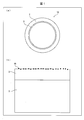
- FIG. 1 shows the structure of an olefin-producing pyrolysis tube 1A in the present embodiment
- (a) is a schematic cross-sectional view of the olefin-producing pyrolysis tube 1A
- (b) is the olefin in (a). It is an enlarged view of the inner surface of 1 A of pyrolysis tubes for manufacture.
- the olefin-producing pyrolysis tube 1A in this embodiment is a metal oxide containing Al 2 O 3 on the inner surface of a tubular base material 2 made of a heat-resistant metal material.
- An alumina film 3 as a physical film is formed, and a dehydrogenation catalyst 4A is supported on the surface of the alumina film 3.
- a metal oxide film containing Al 2 O 3 is referred to as an “alumina film”.
- the olefin-producing pyrolysis tube 1A of the present invention is obtained from hydrocarbon raw materials such as ethane and naphtha by adding a dehydrogenation catalytic reaction to the pyrolysis reaction using the olefin-producing pyrolysis tube 1A.
- the olefin yield can be improved.
- the base material 2, the alumina coating 3, and the dehydrogenation catalyst 4A in the pyrolysis tube 1A for olefin production will be described in detail.
- Base material 2 The base material 2 in the present embodiment is a casting made of a heat-resistant metal material in which an alumina film 3 is formed on the surface of the base material 2.
- the alumina film 3 is more preferably ⁇ -Al 2 O 3 .
- Base material 2 contains at least chromium (Cr): 15 to 50%, nickel (Ni): 18 to 70%, and aluminum (Al): 1 to 6% by mass%.
- the base material 2 includes carbon (C): 0.3 to 0.7%, silicon (Si): 0.1 to 1.5%, manganese (Mn): 0.1 to 3%, chromium (Cr): 15 to 40%, nickel (Ni): 18 to 55%, aluminum (Al): 2 to 4%, rare earth element: 0.005 to 0.4%, tungsten (W): 0.5 to 5% and / or molybdenum (Mo): 0.1 to 3%, with the balance being 25% or more of iron (Fe) and inevitable impurities.
- “%” is all mass% unless otherwise indicated.
- Carbon (C) 0.3 to 0.7% Carbon (C) has the effect of improving the castability and increasing the high temperature creep rupture strength. For this reason, at least 0.3% is contained. However, if the content is excessively large, primary carbides of Cr 7 C 3 are easily formed, and the movement of aluminum (Al) forming the alumina coating 3 is suppressed. For this reason, insufficient supply of aluminum (Al) to the surface portion of the casting occurs, and local severing of the alumina coating 3 occurs, and the continuity of the alumina coating 3 is impaired. Moreover, since secondary carbide precipitates excessively, it causes a reduction in ductility and toughness. For this reason, the upper limit of carbon (C) is set to 0.7%. Carbon (C) is more preferably 0.4 to 0.6%.
- Silicon (Si) 0.1 to 1.5% Silicon (Si) is contained at least 0.1% as a deoxidizer for the molten alloy and to increase the fluidity of the molten alloy, but if the content is too large, the high temperature creep rupture strength is reduced, so the upper limit is 1.5%.
- the upper limit of silicon is more preferably 1.0%.
- Manganese (Mn) 0.1-3% Manganese (Mn) is contained at least 0.1% as a deoxidizer for the molten metal alloy and for fixing sulfur (S) in the molten metal, but if the content is too high, the high temperature creep rupture strength is reduced. Therefore, the upper limit is 3%. The upper limit of manganese (Mn) is more preferably 1.0%.
- Chromium (Cr) 15-50% Chromium (Cr) is contained in an amount of 15% or more for the purpose of contributing to improvement in high temperature strength and repeated oxidation resistance. However, if the content is too high, the high temperature creep rupture strength is lowered, so the upper limit is made 50%. Chromium (Cr) is more preferably 20-30%.
- Nickel (Ni) 18-70%
- Nickel (Ni) is an element necessary for ensuring repeated oxidation resistance and stability of the metal structure, so it is contained in an amount of 18% or more. However, even if the content exceeds 70%, the effect corresponding to the increase cannot be obtained, so the upper limit is made 70%.
- Nickel (Ni) is more preferably 20 to 45%.
- Aluminum (Al) 1-6%
- Aluminum (Al) is an element effective for improving carburization resistance and coking resistance. Moreover, in the structure shown in Claim 2 of this invention, it is an indispensable element in order to produce the alumina membrane
- the aluminum (Al) content is more preferably 2 to 4%.
- the rare earth element means 17 kinds of elements obtained by adding yttrium (Y) and scandium (Sc) to 15 kinds of lanthanum series from lanthanum (La) to lutetium (Lu) in the periodic table.
- the rare earth element has a sulfur (S) fixing ability and an ability to fix an oxide film with a rare earth oxide, and contributes to the promotion of the formation and stabilization of the alumina coating 3, so it is contained in an amount of 0.005% or more. On the other hand, if the content is too large, the ductility and toughness deteriorate, so the upper limit is made 0.4%.
- W tungsten
- Mo molybdenum
- tungsten (W) and molybdenum (Mo) are too large, ductility and carburization resistance are reduced. For this reason, tungsten (W) is 5% or less, and molybdenum (Mo) is 3% or less. More preferably, tungsten (W) is 0.5 to 3% and molybdenum (Mo) is 2% or less.
- the upper limit is 0.6% for titanium (Ti) and zirconium (Zr), and 3.0% for niobium (Nb). More preferably, the upper limit is 0.3% for titanium (Ti) and zirconium (Zr) and 1.5% for niobium (Nb).
- Boron (B) 0.1% or less Boron (B) has an effect of strengthening the grain boundary of the cast body, and can be contained as necessary. In addition, since the fall of creep rupture strength will be caused when content increases, even when adding, it shall be 0.1% or less.
- the diffusion rate of aluminum (Al) in iron (Fe), nickel (Ni), and chromium (Cr) is considered to be faster as the atomic size is smaller. For this reason, by increasing the amount of iron with small atoms and reducing the amount of chromium (Cr), the diffusion of aluminum (Al) in the alloy is enhanced and the aluminum (Al) can be easily moved. The generation of can be promoted.
- iron (Fe) is contained at 25% or more. Note that iron (Fe) is more preferably 30% or more.
- the base material 2 of the olefin-producing pyrolysis tube 1A of the present invention is manufactured by melting a molten metal having the above component composition and casting it to the above composition using centrifugal casting, stationary casting, or the like.
- the obtained base material 2 can be shaped according to the intended use.
- the base material 2 of the present invention is preferably produced by centrifugal casting. This is because by applying centrifugal casting, a fine metal structure grows in the radial direction with the progress of cooling by the mold, and an alloy structure in which aluminum (Al) easily moves can be obtained. Thereby, in the heat treatment described later, it is possible to obtain a cast product having a thin alumina film 3 and having a film having excellent strength even in an environment of repeated heating.
- Examples of cast products produced by centrifugal casting include tubes, particularly pyrolysis tubes used in high-temperature environments.
- the alumina film 3 formed on the inner surface of the base material 2 of the present invention has a high density and has a function as a barrier for preventing oxygen, carbon, and nitrogen from entering the base material 2 from the outside.
- a metal oxide film is not formed on the inner surface of the base material 2. Therefore, excessive decomposition of the hydrocarbon raw material occurs during thermal decomposition due to catalytic action of nickel (Ni), iron (Fe), cobalt (Co), etc., which are constituent elements of the base material 2, and coke is formed on the inner surface of the base material 2. Will be generated.
- the coke generated on the inner surface of the base material 2 is deposited, the heat transfer resistance increases, and the temperature of the outer surface of the olefin production pyrolysis tube rises to maintain the reaction temperature in the olefin pyrolysis tube. There was a problem.
- the formation of coke on the inner surface can be suppressed by forming the alumina coating 3 on the inner surface of the base material 2. As a result, the frequency of decoking can be reduced.
- the alumina coating 3 of the present invention is formed by a surface treatment process and a first heat treatment process.
- the surface treatment step and the first heat treatment step will be described in detail.
- the surface treatment process is a process for performing surface treatment on a target portion of the base material 2 that will come into contact with a high temperature atmosphere when the product is used, and adjusting the surface roughness of the portion.
- the surface treatment of the base material 2 can be exemplified by a polishing treatment.
- the surface treatment can be performed so that the surface roughness (Ra) of the target site is 0.05 to 2.5 ⁇ m. More desirably, the surface roughness (Ra) is 0.5 to 2.0 ⁇ m.
- the residual stress and distortion of the heat affected zone can be removed at the same time.
- the first heat treatment step is a step for performing heat treatment on the base material 2 after the surface treatment step in an oxidizing atmosphere.
- An oxidizing atmosphere is an oxidizing gas containing 20% by volume or more of oxygen, or an oxidizing environment in which steam or CO 2 is mixed.
- the heat treatment is performed at a temperature of 900 ° C. or higher, preferably 1000 ° C. or higher, and the heating time is 1 hour or longer.
- the thickness of the alumina coating 3 formed on the inner surface of the base material 2 is preferably 0.5 ⁇ m or more and 6 ⁇ m or less in order to effectively exhibit the barrier function. If the thickness of the alumina coating 3 is less than 0.5 ⁇ m, the carburization resistance may decrease. If the thickness exceeds 6 ⁇ m, the alumina coating 3 is affected by the difference in the thermal expansion coefficient between the base material 2 and the coating. 3 may be easily peeled off.
- the thickness of the alumina coating 3 is 0.5 ⁇ m or more and 2.5 ⁇ m or less.
- a chromium oxide scale may be partially formed on the alumina coating 3 in some cases. This is because the chromium oxide scale formed near the surface of the base material 2 is pushed up to the product surface by Al 2 O 3 .
- the chromium oxide scale should be small, and it is preferable that Al 2 O 3 occupy 80 area% or more so that it is less than 20 area% on the product surface.
- the dehydrogenation catalyst 4A is used to improve the yield of olefins in a thermal decomposition reaction (specifically, a reaction in which a hydrocarbon raw material such as naphtha or ethane is thermally decomposed into olefins) using the olefin production thermal decomposition tube 1A. And is supported on the surface of the alumina coating 3.
- the dehydrogenation catalyst 4A is a catalyst component including at least one of the group consisting of an oxide of a group 2B metal element, an oxide of a group 3B metal element, and an oxide of a group 4B metal element of the periodic table Consists of only. More preferably, the dehydrogenation catalyst 4A is composed of Zn oxide (ZnO), Ga oxide (Ga 2 O 3 ), Sn oxide (SnO or SnO 2 ), Ge oxide (GeO 2 ), and In oxide. It is constituted only by the catalyst component comprising at least one of the group consisting of (in 2 O 3).
- Patent Document 2 discloses a perovskite-type catalyst, particularly a perovskite-type catalyst using an element that forms a basic oxide such as barium (Ba), cerium (Ce), zirconium (Zr), and yttrium (Y).
- a basic oxide such as barium (Ba), cerium (Ce), zirconium (Zr), and yttrium (Y).
- catalysts have been disclosed, the inventors have intensively studied that the oxides of Group 2B metal elements, 3B metal element oxides, which are acidic oxides rather than basic oxides, and 4B group metal element oxides, more preferably zinc (Zn), gallium (Ga), tin (Sn), germanium (Ge), and indium (In) oxides, such as hydrocarbons such as ethane and naphtha It was found to be effective as a catalyst in the production of olefins by pyrolysis of benzene.
- oxides such as iron (Fe), cobalt (Co), nickel (Ni) are used as catalysts, excessive decomposition of the hydrocarbon raw material occurs during thermal decomposition, and a large amount of coke (carbon) is formed on the surface of the alumina coating. This is not preferable because it may be generated at a time.
- coating process is a process of apply
- metal salt for example, nitrate or acetate can be used.
- the second heat treatment step is a step of heat-treating the base material 2 in which the metal salt aqueous solution is applied to the alumina coating 3 by the application step.
- the heat treatment in the second heat treatment step is performed in air or oxygen.
- the heat treatment temperature in the second heat treatment step is in the range of 500 to 900 ° C., and the heat treatment time is 1 to 6 hours.
- the metal ions in the metal salt are oxidized, and a metal oxide, that is, a dehydrogenation catalyst 4A is formed.
- a dehydrogenation catalyst 4A can be supported on the alumina coating 3.
- the dehydrogenation catalyst 4A can be supported on the alumina film 3 at an appropriate concentration (amount) by adjusting the concentration of the aqueous metal salt solution applied in the application step.
- the specific surface area of the dehydrogenation catalyst 4A is preferably 2 to 100 m 2 / g, and 3 to 10 m 2 / g. It is more preferable.
- the alumina coating 3 is formed on the inner surface of the tubular base material 2 made of a heat-resistant metal material, and dehydration is performed on the surface of the alumina coating 3.
- An elementary catalyst 4A is supported.
- the alumina film 3 is formed on the inner surface of the base material 2. For this reason, it can suppress that a coke produces
- a dehydrogenation catalyst 4A is supported on the surface of the alumina coating 3.
- the dehydrogenation catalyst 4A is selected from the group consisting of an oxide of a 2B group metal element, an oxide of a 3B group metal element, and an oxide of a 4B group metal element in the periodic table. It is comprised only by the catalyst component containing at least one. More preferably, the dehydrogenation catalyst 4A is composed of Zn oxide (ZnO), Ga oxide (Ga 2 O 3 ), Sn oxide (SnO or SnO 2 ), Ge oxide (GeO 2 ), and In oxide. It is constituted only by the catalyst component comprising at least one of the group consisting of (in 2 O 3).
- these metal oxides function as a dehydrogenation catalyst in the thermal decomposition of olefins produced from hydrocarbon raw materials such as ethane and naphtha, the yield of olefins such as ethylene can be improved. Yes.
- the metal salt aqueous solution containing the metal element constituting the dehydrogenation catalyst 4A is applied to the alumina coating 3 in the coating step, and heat treated in the second heat treatment step, so that the dehydrogenation catalyst 4A is alumina.
- the thermal decomposition tube for olefin manufacture of this invention is not restricted to this.
- the dehydrogenation catalyst 4A is manufactured in advance, the slurry containing the dehydrogenation catalyst 4A is applied to the alumina film 3 in the application step, and the slurry containing the dehydrogenation catalyst 4A is applied in the second heat treatment step.
- the dehydrogenation catalyst 4A may be supported on the alumina coating 3 by heat-treating the base material 2. In this case, the dehydrogenation catalyst 4A is produced in advance by any known method.
- the dehydrogenation catalyst 4A is obtained by performing the coating step and the second heat treatment step on the alumina coating 3 formed on the inner surface of the base material 2 by the surface treatment step and the first heat treatment step.
- the olefin-producing pyrolysis tube of the present invention is not limited to this.
- the application process and the heat treatment process may be performed after the surface treatment process.
- the alumina coating 3 is formed on the inner surface of the base material 2 and the dehydrogenation catalyst 4A is supported on the alumina coating 3 in the heat treatment step.
- the alumina film 3 can be formed on the inner surface of the base material 2 and the dehydrogenation catalyst 4A can be supported on the alumina film 3 by performing the heat treatment step only once.
- the dehydrogenation catalyst 4A is supported on the surface of the alumina coating 3 formed on the inner surface of the base material 2, but the pyrolysis tube 1A for olefin production of the present invention is used. Is not limited to this. That is, the pyrolysis tube for producing olefin of one embodiment of the present invention has a barrier function and can support the dehydrogenation catalyst 4A, which is a metal oxide film different from Al 2 O 3 (for example, Cr 2 O 3 , MnCr The dehydrogenation catalyst 4A may be supported on the surface of 2 O 4 or the like.
- FIG. 2 shows the configuration of the olefin-producing pyrolysis tube 1A ′
- (a) is a schematic cross-sectional view of the olefin-producing pyrolysis tube 1A ′
- (b) is for olefin production in (a). It is an enlarged view of the inner surface of pyrolysis tube 1A '.
- the inner surface of the base 2 are alumina film 3 is formed of a metal oxide film containing Al 2 O 3, the surface of the alumina film 3, dried
- the elementary catalyst 4A was supported.
- the modified pyrolysis tube 1A ′ for olefin production is directly dehydrated on the inner surface of the tubular base material 2 made of a heat-resistant metal material, as shown in FIGS. The point that the raw catalyst 4A is supported is different from the olefin-producing pyrolysis tube 1A.
- the dehydrogenation catalyst 4A can be supported on the inner surface of the base material 2 by applying and heat-treating under appropriate conditions such as air or nitrogen atmosphere.
- the dehydrogenation catalyst 4A is supported on the inner surface of the base material 2 in the olefin-producing pyrolysis tube 1A ′.
- ethylene can be generated, for example, from ethane by a dehydrogenation reaction.
- the yield of olefins from hydrocarbon raw materials such as ethane and naphtha by thermal decomposition can be improved.
- the configuration of the dehydrogenation catalyst is different from that of the dehydrogenation catalyst 4A in the first embodiment.
- FIG. 3 shows the configuration of the olefin-producing pyrolysis tube 1B in this embodiment, (a) is a schematic cross-sectional view of the olefin-producing pyrolysis tube 1B, and (b) is the olefin in (a). It is an enlarged view of the inner surface of the thermal decomposition tube 1B for manufacture.
- the dehydrogenation catalyst 4B in the olefin production pyrolysis tube 1B of this embodiment includes a catalyst component 4Ba and a carrier 4Bb carrying the catalyst component. .
- the catalyst component 4Ba is a catalyst component for improving the olefin yield in a thermal decomposition reaction in which a hydrocarbon raw material such as ethane or naphtha is thermally decomposed into olefins in the dehydrogenation catalyst 4B.
- the catalyst component 4Ba includes at least one of the group consisting of an oxide of a group 2B metal element, an oxide of a group 3B metal element, and an oxide of a group 4B metal element of the periodic table. More preferably, the catalyst component 4Ba includes Zn oxide (ZnO), Ga oxide (Ga 2 O 3 ), Sn oxide (SnO or SnO 2 ), Ge oxide (GeO 2 ), and In oxide (In 2 O 3 ).
- the carrier 4Bb is a carrier on which the catalyst component 4Ba is supported in the dehydrogenation catalyst 4B.
- the carrier 4Bb in the present embodiment is made of Al 2 O 3 .
- the carrier 4Bb preferably has a large specific surface area in order to improve the function of the catalyst component 4Ba as a catalyst.
- the specific surface area of Al 2 O 3 as the carrier 4Bb is preferably 20 m 2 / g or more, and more preferably 40 m 2 / g or more.
- the catalyst component 4Ba can be highly dispersed in the carrier 4Bb.
- the olefin yield can be improved in the pyrolysis reaction in which the hydrocarbon raw material is pyrolyzed into olefin.
- Al 2 O 3 has four phases of ⁇ -Al 2 O 3 , ⁇ -Al 2 O 3 , ⁇ -Al 2 O 3 and ⁇ -Al 2 O 3 .
- the phase changes in the order of Al 2 O 3 ), and the specific surface area decreases as the phase changes.
- ⁇ -Al 2 O 3 that undergoes phase transformation at the highest temperature has a specific surface area of 15 m 2 / g or less.
- the carrier 4Bb of the dehydrogenation catalyst 4B in the present embodiment preferably has a specific surface area of 20 m 2 / g or more as described above. This is because the carrier 4Bb is ⁇ -Al 2 O 3 , ⁇ -Al. It means that a structure mainly composed of 2 O 3 or ⁇ -Al 2 O 3 is preferable.
- the Al 2 O 3 as the support 4Bb is not less than 1300 ° C. before the heat treatment. It is not a single phase unless after heat treatment at a high temperature of ⁇ -Al 2 O 3 , ⁇ -Al 2 O 3 , ⁇ -Al 2 O 3 , and ⁇ -Al 2 O 3. It is assumed that Therefore, the specific surface area of Al 2 O 3 as the support 4Bb is an average value of the specific surface areas of Al 2 O 3 in which the above phases are mixed.
- the carrier 4Bb preferably forms a composite oxide or a solid solution with the catalyst component 4Ba in the production of the dehydrogenation catalyst 4B.
- the carrier 4Bb preferably forms a composite oxide or a solid solution with the catalyst component 4Ba in the production of the dehydrogenation catalyst 4B.
- ⁇ Method for Producing Dehydrogenation Catalyst 4B> a method for producing the dehydrogenation catalyst 4B will be described.
- two types of dehydrogenation catalysts (1) when ⁇ -Al 2 O 3 is used as a starting material for the support 4Bb and (2) when ⁇ -Al 2 O 3 is used as a starting material for the support 4Bb The manufacturing method of 4B is demonstrated.
- the dehydrogenation catalyst 4B includes a metal element constituting the catalyst component 4Ba in ⁇ -Al 2 O 3 as a starting material for the support 4Bb.
- a metal salt eg, nitrate or acetate
- the heat treatment is performed in air or oxygen
- the heat treatment temperature is in the range of 500 to 1300 ° C.
- the heat treatment time is 1 to 6 hours.
- a dehydrogenation catalyst 4B in which the catalyst component 4Ba is supported on ⁇ -Al 2 O 3 as the carrier 4Bb can be obtained.
- ⁇ -Al 2 O 3 is used as the starting material for the support 4Bb
- the dehydrogenation catalyst 4B contains the metal element constituting the catalyst component 4Ba in ⁇ -Al 2 O 3 as the starting material for the support 4Bb.
- It can be produced by attaching a metal salt (eg, nitrate or acetate) aqueous solution (attachment step) and then heat-treating the metal salt aqueous solution ⁇ -Al 2 O 3 (heat treatment step).
- the heat treatment is performed in air or oxygen, the heat treatment temperature is in the range of 500 to 1300 ° C., and the heat treatment time is 1 to 6 hours.
- the catalyst component 4Ba becomes Al 2 O 3 ( ⁇ -Al 2 O 3 , ⁇ -Al 2 O 3 , ⁇ -Al 2 O 3 , or ⁇ -Al 2 O 3 as the support 4Bb. Can be obtained.
- the heat treatment temperature is preferably in the range of 500 to 1100 ° C. This is because, when the heat treatment temperature is in the range of 500 to 1100 ° C., it is possible to prevent ⁇ -Al 2 O 3 from completely transforming into ⁇ -Al 2 O 3 during the heat treatment. The decrease in the specific surface area of Al 2 O 3 can be suppressed. As a result, the catalyst component 4Ba can be highly dispersed in Al 2 O 3 as a support.
- the heat treatment temperature is more preferably in the range of 1000 to 1100 ° C. This is because when the heat treatment temperature is in the range of 1000 ⁇ 1100 °C, Al 2 O 3 when at least a portion of the ⁇ -Al 2 O 3 during the heat treatment is phase transformation ⁇ -Al 2 O 3, a phase transformation This is because at least a part of the compound is combined with the catalyst component 4Ba (particularly, gallium oxide) to form a composite oxide or a solid solution. Thereby, in the thermal decomposition reaction which thermally decomposes a hydrocarbon raw material into an olefin, it can suppress that catalyst component 4Ba aggregates.
- the heat treatment temperature is more preferably in the range of 1000 to 1080 ° C. This is because when the heat treatment temperature is in the range of 1000 to 1080 ° C., the rate of phase transformation of ⁇ -Al 2 O 3 to ⁇ -Al 2 O 3 during the heat treatment can be increased.
- the method for supporting the dehydrogenation catalyst 4B on the alumina film 3 includes a coating step and a third heat treatment step. Below, an application
- coating process is a process of apply
- the third heat treatment step is a step of heat-treating the base material 2 in which the slurry containing the dehydrogenation catalyst 4B is applied to the alumina film 3 by the application step.
- the heat treatment in the third heat treatment step is performed in air or oxygen.
- the heat treatment temperature in the third heat treatment step is in the range of 500 to 900 ° C., and the heat treatment time is 1 to 6 hours.
- the dehydrogenation catalyst 4B can be supported on the alumina film 3 by executing the third heat treatment step under the above heat treatment conditions.
- the dehydrogenation catalyst 4B can be supported on the alumina coating 3 at an appropriate concentration (amount) by adjusting the concentration of the slurry applied in the application step.
- the specific surface area of the dehydrogenation catalyst 4B is preferably 2 to 200 m 2 / g, and 10 to 150 m 2 / g. More preferably, it is more preferably 20 to 100 m 2 / g. Further, since most of Al 2 O 3 as the support 4Bb is ⁇ -Al 2 O 3 , the specific surface area of the dehydrogenation catalyst 4B is most preferably 40 to 100 m 2 / g.
- the olefin-producing pyrolysis tube 1B in the present embodiment has the alumina coating 3 formed on the inner surface of the tubular base material 2 made of a heat-resistant metal material, and on the surface of the alumina coating 3, A dehydrogenation catalyst 4B is supported.
- the dehydrogenation catalyst 4B includes a catalyst component 4Ba and a carrier 4Bb that supports the catalyst component 4Ba.
- the catalyst component 4Ba includes at least one of the group consisting of an oxide of a group 2B metal element, an oxide of a group 3B metal element, and an oxide of a group 4B metal element of the periodic table.
- the catalyst component 4Ba includes Zn oxide (ZnO), Ga oxide (Ga 2 O 3 ), Sn oxide (SnO or SnO 2 ), Ge oxide (GeO 2 ), and In oxide (In 2 O 3 ).
- the carrier 4Bb is made of Al 2 O 3 , and more preferably, at least a part of the carrier 4Bb is made of ⁇ -Al 2 O 3 .
- the dehydrogenation catalyst 4B in which the catalyst component 4Ba is supported on the support 4Bb is supported on the surface of the alumina film 3, so The surface area can be increased.
- the number of hydrocarbon dehydrogenation catalytic reaction sites can be increased, and the olefin yield from hydrocarbon raw materials such as ethane and naphtha can be improved. It has become.
- the carrier 4Bb on which the dehydrogenation catalyst is supported is made of Al 2 O 3 .
- the pyrolysis tube for olefin production of the present invention is not limited to this, and SiO 2 , TiO 2 , ZrO 2 , MgO, La 2 O 3 or a composite oxide containing these may be used as a support.
- Al 2 O 3 is more preferable in terms of surface area.
- the dehydrogenation catalyst 4B is obtained by performing the coating step and the third heat treatment step on the alumina coating 3 formed on the inner surface of the base material 2 by the surface treatment step and the first heat treatment step.
- the olefin-producing pyrolysis tube of the present invention is not limited to this.
- Al 2 O 3 to which an aqueous metal salt solution containing a metal element constituting the catalyst component 4Ba is applied may be applied to the inner surface of the base material 2 after the surface treatment step, and the heat treatment step may be performed.
- the alumina film 3 is formed on the inner surface of the base material 2 and the metal in the metal salt is oxidized to dehydrogenate the metal oxide supported on Al 2 O 3 .
- the catalyst 4B is supported on the alumina coating 3. Thereby, the alumina film 3 can be formed on the inner surface of the base material 2 and the dehydrogenation catalyst 4B can be supported on the alumina film 3 by performing the heat treatment step only once.
- the olefin production pyrolysis tube of one embodiment of the present invention is Alternatively, the dehydrogenation catalyst 4B may be directly supported on the inner surface of the tubular base material 2 made of a heat-resistant metal material.
- the pyrolysis tube for olefin production is not limited to the type in which a film is formed on the inner surface of the cast body as in the cast product described in Patent Document 1, but for the purpose of fluid agitation and surface area increase. There is also a type in which protrusions such as fins are provided on the inner surface of a production pyrolysis tube.
- the dehydrogenation catalyst 4A or the dehydrogenation catalyst 4B is supported on the above-described pyrolysis tube for producing olefin having the protrusions provided on the inner surface. It may be a configuration. Thereby, the pyrolysis tube for olefin production of one embodiment of the present invention can increase the olefin yield.
- a metal oxide as a catalyst component is supported on powdery ⁇ -Al 2 O 3 as a support for supporting the catalyst component.
- the dehydrogenation catalyst used was used.
- powdery ⁇ -Al 2 O 3 not supporting the dehydrogenation catalyst was used.
- JRC-ALO-6 which is a catalyst catalyst reference catalyst
- the dehydrogenation catalyst in Example 1 was produced by applying an aqueous zinc nitrate (Zn (NO 3 ) 2 ) solution to ⁇ -Al 2 O 3 as a support and calcining in the atmosphere at 700 ° C. for 3 hours. At this time, the amount of zinc (Zn) was adjusted to 5% by weight with respect to the total amount of zinc (Zn) and ⁇ -Al 2 O 3 . Zinc oxide (ZnO) formed by firing had a particle size of about 20 nm. Below, the dehydrogenation catalyst obtained by the said method is called a 700Zn catalyst.
- Example 2 and Example 3 an aqueous solution of zinc nitrate (Zn (NO 3 ) 2 ) is applied to ⁇ -Al 2 O 3 as a support and calcined in the atmosphere at 850 ° C. for 3 hours. It was manufactured by. At this time, the amount of zinc (Zn) was adjusted to 5% by weight with respect to the total amount of zinc (Zn) and ⁇ -Al 2 O 3 . Zinc oxide (ZnO) formed by firing had a particle size of about 30-50 nm. Below, the dehydrogenation catalyst obtained by the said method is called an 850Zn catalyst.
- the dehydrogenation catalysts in Examples 4 to 6 were prepared by applying an aqueous solution of gallium nitrate (Ga (NO 3 ) 3 ) to ⁇ -Al 2 O 3 as a support and firing at 850 ° C. for 3 hours in the air. Manufactured. At this time, the amount of gallium (Ga) was adjusted to 5% by weight with respect to the total amount of gallium (Ga) and ⁇ -Al 2 O 3 .
- Gallium oxide (Ga 2 O 3 ) formed by firing had a particle size of about 10 to 25 nm.
- the dehydrogenation catalyst obtained by the said method is called an 850Ga catalyst.
- the dehydrogenation catalyst in Comparative Example 4 was produced by applying an iron nitrate (Fe (NO 3 ) 3 ) aqueous solution to ⁇ -Al 2 O 3 as a support and firing at 850 ° C. for 3 hours in the air. . At this time, the amount of iron (Fe) was adjusted to 5% by weight with respect to the total amount of iron (Fe) and ⁇ -Al 2 O 3 .
- the dehydrogenation catalyst obtained by the above method is referred to as an 850Fe catalyst.
- a mixture of 100 mg of a sample 700 Zn catalyst, 850 Zn catalyst, 850 Ga catalyst, 850 Fe catalyst, or ⁇ -Al 2 O 3 ) and 392 mg of inert solid SiC was mixed with a quartz tube. (Inner diameter 4 mm, length 180 mm) was filled at a height of 30 mm.
- the quartz tube was inserted into a tubular furnace, and the temperature in the quartz tube was raised to the target reaction temperature (test temperature).
- gas was supplied to the quartz tube, and ethane was thermally decomposed in the quartz tube.
- the raw material flow rates were ethane (C 2 H 6 ): 36.2 mL / min, steam (H 2 O): 49.4 mL / min, N2: 196 mL / min.
- hydrogen (H 2 ) and nitrogen (N 2 ) are converted to TCG gas chromatograph (Shimadzu, GC-8A), ethane (C 2 H 6 ), ethylene (C 2 H 4 ), monoxide.
- Carbon (CO) and methane (C 2 H 4 ) were analyzed using a FID gas chromatograph (Shimadzu, GC-8A) equipped with a methanizer, and conversion of ethane (C 2 H 6 ) as shown in Table 1 rate (mol%), the selectivity of ethylene (C 2 H 4) (mol%), and the yield (mol%) of ethylene (C 2 H 4) was calculated.
- Example 1 a 700Zn catalyst was used and the reaction temperature was 700 ° C.
- Examples 2 and 3 an 850Zn catalyst was used, and the reaction temperatures were 750 ° C and 800 ° C, respectively.
- Examples 4 to 6 an 850Ga catalyst was used, and the reaction temperatures were 700 ° C., 750 ° C., and 800 ° C., respectively.
- Comparative Examples 1 to 3 powdery ⁇ -Al 2 O 3 not supporting the dehydrogenation catalyst was used, and the reaction temperatures were 700 ° C., 750 ° C., and 800 ° C., respectively.
- an 850Fe catalyst was used and the reaction temperature was 700 ° C.
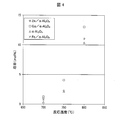
- FIG. 4 is a graph showing the ethylene yield with respect to the reaction temperature in Examples 1 to 6 and Comparative Examples 1 to 4 of the present invention.
- the data shown in FIG. 4 and Table 1 were calculated by analyzing the gas flowing out of the quartz tube 30 minutes after the start of the reaction.
- Examples 1 to 6 using a dehydrogenation catalyst containing zinc oxide (ZnO) or gallium oxide (Ga 2 O 3 ) as a catalyst component supported the dehydrogenation catalyst.
- a dehydrogenation catalyst containing zinc oxide (ZnO) or gallium oxide (Ga 2 O 3 ) as a catalyst component functions as a catalyst in the ethane thermal decomposition reaction.
- the dehydrogenation catalyst of Catalyst Example 1 was prepared by applying an aqueous solution of gallium nitrate (Ga (NO 3 ) 3 ) to ⁇ -Al 2 O 3 as a starting material for a dehydrogenation catalyst support, and at 850 ° C. in the atmosphere. It was manufactured by firing for 3 hours. At this time, the amount of gallium (Ga) were prepared such that the 5% by weight relative to the total amount of the gallium (Ga) and Al 2 O 3.
- Ga (NO 3 ) 3 gallium nitrate
- the dehydrogenation catalyst of Catalyst Example 2 was produced in the same manner as the dehydrogenation catalyst of Catalyst Example 1 except that the calcination temperature was 1050 ° C.
- the dehydrogenation catalyst of Catalyst Example 3 was produced in the same manner as the dehydrogenation catalyst of Catalyst Example 1 except that the calcination temperature was 1300 ° C.
- the dehydrogenation catalyst of Catalyst Example 4 was produced in the same manner as the dehydrogenation catalyst of Catalyst Example 1, except that ⁇ -Al 2 O 3 was used as the starting material for the dehydrogenation catalyst support.
- the dehydrogenation catalyst of Catalyst Example 5 was produced in the same manner as the dehydrogenation catalyst of Catalyst Example 4 except that the calcination temperature was 1000 ° C.
- the dehydrogenation catalyst of Catalyst Example 6 was produced in the same manner as the dehydrogenation catalyst of Catalyst Example 4 except that the calcination temperature was 1050 ° C.
- the dehydrogenation catalyst of Catalyst Example 7 was produced in the same manner as the dehydrogenation catalyst of Catalyst Example 4 except that the calcination temperature was 1300 ° C.
- Comparative Example 5 powdered ⁇ -Al 2 O 3 (JRC-ALO-6, which is a reference catalyst of the Catalysis Society of Japan) was used.
- Catalysts using ⁇ -Al 2 O 3 as starting material for the dehydrogenation catalyst support In the dehydrogenation catalysts of Examples 1 to 3, only the diffraction peak of ⁇ -Al 2 O 3 was observed (not shown). ). That is, in the dehydrogenation catalysts of Catalyst Examples 1 to 3, gallium oxide was supported on ⁇ -Al 2 O 3 as a starting material.
- the dehydrogenation catalyst of Catalyst Examples 4 to 8 using ⁇ -Al 2 O 3 as a starting material for the dehydrogenation catalyst support the dehydrogenation catalyst of Catalyst Example 4 heat-treated at 850 ° C. , ⁇ -Al 2 O 3 diffraction peak was observed (not shown). That is, in the dehydrogenation catalyst of Catalyst Example 4, gallium oxide was supported on ⁇ -Al 2 O 3 as a starting material.
- the results of X-ray diffraction analysis performed on the dehydrogenation catalysts of Catalyst Examples 5 to 7 are shown in FIG. As shown in FIG. 5, in the dehydrogenation catalyst of Catalyst Example 5 heat-treated at 1000 ° C.
- the diffraction peak of ⁇ -Al 2 O 3 is the main. It was seen in. That is, in the dehydrogenation catalysts of Catalyst Examples 5 and 6, gallium oxide (or a part of gallium oxide) was supported on a carrier mainly composed of ⁇ -Al 2 O 3 . In addition, in the dehydrogenation catalyst of Catalyst Example 6, a diffraction peak of ⁇ -Al 2 O 3 was simultaneously observed in addition to the diffraction peak of ⁇ -Al 2 O 3 . Further, as shown in FIG.
- FIG. 6 shows ethylene yield in a ethane pyrolysis experiment using dehydrogenation catalysts of Catalyst Examples 1 to 4, 6 and 7 and powdered ⁇ -Al 2 O 3 as Comparative Example 5. It is a graph which shows the time change of a rate. As shown in FIG. 6, the dehydrogenation catalysts of Catalyst Examples 1 to 4, 6 and 7 had a higher ethylene yield than the powdery ⁇ -Al 2 O 3 as Comparative Example 5.
- the specific surface area of the dehydrogenation catalyst of Catalyst Example 6 was about 10 times that of the dehydrogenation catalysts of Catalyst Examples 2 and 3. This is because in the dehydrogenation catalysts of Catalyst Examples 2 and 3, Al 2 O 3 as the support is mainly ⁇ -Al 2 O 3 having a small specific surface area, whereas dehydrogenation of Catalyst Example 6 is performed. This is because in the catalyst, Al 2 O 3 as the support is mainly ⁇ -Al 2 O 3 having a large specific surface area.
- FIG. 7 shows the results obtained by using TEM-EDS (energy dispersive spectroscopic-transmission electron microscope) for the dehydrogenation catalysts of Catalyst Examples 2 and 6, and HAADF (High-Angle) It is a figure which shows the EDS mapping measurement result of an Annular Dark Field) image and Al and Ga.
- TEM-EDS energy dispersive spectroscopic-transmission electron microscope
- HAADF High-Angle
- the pyrolysis tube for olefin production has a configuration in which a dehydrogenation catalyst is supported on the inner surface of a tubular base material made of a heat-resistant metal material.
- the dehydrogenation catalyst can act as a dehydrogenation catalyst in the thermal decomposition reaction of the hydrocarbon raw material.
- hydrocarbon raw materials such as ethane and naphtha
- a metal oxide film is formed on the inner surface of a tubular base material made of a heat-resistant metal material, and dehydration is performed on the surface of the metal oxide film.
- an elementalization catalyst is supported.
- the metal oxide film since the metal oxide film is formed on the inner surface of the base material, the metal oxide film serves as a barrier to prevent oxygen, carbon, nitrogen, etc. from entering the base material. be able to.
- a dehydrogenation catalyst is supported on the surface of the metal oxide film.
- a dehydrogenation catalyst can act as a catalyst in the thermal decomposition reaction of a hydrocarbon raw material.
- hydrocarbon raw materials such as ethane and naphtha
- nickel (Ni) or the like contained in the base material has an action of promoting the formation of coke, it is possible to prevent the hydrocarbon raw material and the heat-resistant metal material from being in direct contact with each other by forming a metal oxide film. .
- the metal oxide film is composed of at least one of the group consisting of Al 2 O 3 , Cr 2 O 3 , and MnCr 2 O 4. Preferably there is. These metal oxides have a barrier function and can carry a dehydrogenation catalyst.
- oxygen, carbon, nitrogen and the like can be prevented from entering, and the dehydrogenation catalyst can be supported on the surface of the pyrolysis tube.
- the dehydrogenation catalyst includes, as a catalyst component, an oxide of a group 2B metal element, an oxide of a group 3B metal element, and a group 4B of the periodic table. It is preferable that the structure includes at least one of the group consisting of oxides of the metal elements.
- the oxide of the group 2B metal element, the group 3B metal element oxide, and the group 4B metal element oxide of the periodic table are carbonized such as ethane or naphtha as an acidic oxide. It functions as a catalyst that promotes the dehydrogenation reaction of the hydrogen raw material.
- the yield of the produced olefin can be improved.
- the dehydrogenation catalyst is selected from the group consisting of Zn oxide, Ga oxide, Sn oxide, Ge oxide, and In oxide as a catalyst component.
- a configuration including at least one is preferable.
- Zn oxide, Ga oxide, Sn oxide, Ge oxide, and In oxide are catalysts that promote dehydrogenation reaction of hydrocarbon raw materials such as ethane and naphtha as acidic oxides. Function as.
- the yield of the produced olefin can be improved.
- the dehydrogenation catalyst may include the catalyst component and a carrier that supports the catalyst component.
- the carrier is preferably Al 2 O 3 .
- the dehydrogenation catalyst including the catalyst component and the carrier supporting the catalyst component is supported on the surface of the base material or the metal oxide film.
- carrier can be enlarged.
- the number of hydrocarbon dehydrogenation reaction sites can be increased, and the olefin yield from hydrocarbon raw materials such as ethane and naphtha can be improved.
- the specific surface area of Al 2 O 3 as the carrier is preferably 20 m 2 / g or more.
- the catalyst component can be highly dispersed on the carrier.
- the olefin yield can be improved in the pyrolysis reaction in which the hydrocarbon raw material is pyrolyzed into olefin.
- the catalyst component is a Ga oxide, and at least a part of Al 2 O 3 as the support is ⁇ -Al 2 O 3. preferable.
- the Ga oxide and ⁇ -Al 2 O 3 form a composite oxide, it is possible to suppress aggregation of the catalyst component 4Ba in the thermal decomposition reaction in which the hydrocarbon raw material is thermally decomposed into olefins. can do. As a result, a state where the olefin yield is high can be maintained for a long period of time, so that the olefin yield can be further improved.
- a method for producing a dehydrogenation catalyst of one embodiment of the present invention is a method for producing a dehydrogenation catalyst supported on the above-described pyrolysis tube for producing olefin, which is a metal element of group 2B and group 3B of the periodic table.
- ⁇ -Al 2 O 3 is ⁇ -Al 2 having a small specific surface area in the heat treatment step. It is possible to suppress complete phase transformation to O 3 . Thus, it is possible to suppress the reduction of the specific surface area of Al 2 O 3 as support. As a result, the catalyst component can be highly dispersed in Al 2 O 3 as a support.
- the heat treatment temperature in the heat treatment step is preferably in the range of 1000 to 1100 ° C.
- At least a portion of the ⁇ -Al 2 O 3 is phase transformation ⁇ -Al 2 O 3 during the heat treatment, theta-Al 2 when phase transformation It is considered that O 3 is combined with a catalyst component at least part of Al 2 O 3 to form a composite oxide. Thereby, it can suppress that a catalyst component aggregates in the thermal decomposition reaction which thermally decomposes a hydrocarbon raw material into an olefin.
- the present invention can be used in a pyrolysis tube that thermally decomposes hydrocarbon raw materials such as ethane and naphtha into olefins.
Landscapes
- Chemical & Material Sciences (AREA)
- Engineering & Computer Science (AREA)
- Materials Engineering (AREA)
- Organic Chemistry (AREA)
- Chemical Kinetics & Catalysis (AREA)
- Organic Low-Molecular-Weight Compounds And Preparation Thereof (AREA)
- Catalysts (AREA)
- Low-Molecular Organic Synthesis Reactions Using Catalysts (AREA)
- Production Of Liquid Hydrocarbon Mixture For Refining Petroleum (AREA)
Abstract
Tuyau de décomposition thermique pour la fabrication d'oléfines qui peut améliorer les rendements d'oléfines dans des réactions de décomposition thermique de matières premières d'hydrocarbures. Un tuyau de décomposition thermique pour un fabricant d'oléfines (1A) supporte un catalyseur de déshydrogénation (4A) sur la surface intérieure du matériau de base (2), qui est formé à partir d'un matériau métallique résistant à la chaleur et formé selon une forme de tuyau.
Priority Applications (3)
| Application Number | Priority Date | Filing Date | Title |
|---|---|---|---|
| US16/302,777 US11427763B2 (en) | 2016-05-20 | 2017-04-04 | Pyrolysis tube for manufacturing olefin and method for manufacturing dehydrogenating catalyst |
| CA3024827A CA3024827C (fr) | 2016-05-20 | 2017-04-04 | Tuyau de decomposition thermique pour fabrication d'olefines et procede de fabrication de catalyseur de deshydrogenation |
| SA518400441A SA518400441B1 (ar) | 2016-05-20 | 2018-11-15 | أنبوب انحلال حراري لتصنيع الألفين وطريقة لتصنيع محفز لنزع الهيدروجين |
Applications Claiming Priority (4)
| Application Number | Priority Date | Filing Date | Title |
|---|---|---|---|
| JP2016101731 | 2016-05-20 | ||
| JP2016-101731 | 2016-05-20 | ||
| JP2016-222717 | 2016-11-15 | ||
| JP2016222717A JP6785133B2 (ja) | 2016-05-20 | 2016-11-15 | オレフィン製造用熱分解管および脱水素化触媒の製造方法 |
Publications (1)
| Publication Number | Publication Date |
|---|---|
| WO2017199612A1 true WO2017199612A1 (fr) | 2017-11-23 |
Family
ID=60324882
Family Applications (1)
| Application Number | Title | Priority Date | Filing Date |
|---|---|---|---|
| PCT/JP2017/014119 Ceased WO2017199612A1 (fr) | 2016-05-20 | 2017-04-04 | Tuyau de décomposition thermique pour fabrication d'oléfines et procédé de fabrication de catalyseur de déshydrogénation |
Country Status (2)
| Country | Link |
|---|---|
| SA (1) | SA518400441B1 (fr) |
| WO (1) | WO2017199612A1 (fr) |
Citations (8)
| Publication number | Priority date | Publication date | Assignee | Title |
|---|---|---|---|---|
| US2265641A (en) * | 1938-05-24 | 1941-12-09 | Jasco Inc | Production of butadiene by the dehydrogenation of butylene |
| JPS51125007A (en) * | 1974-09-03 | 1976-11-01 | Petro Tex Chem Corp | Modified zinc ferrite oxidative dehydrogenation catalyst |
| US5414182A (en) * | 1992-03-11 | 1995-05-09 | Snamprogetti S.P.A. | Process for activating catalyst percursors for the dehydrogenation of C.sub. -C5 paraffins, and a catalytic composition activated by the process |
| JPH1129776A (ja) * | 1997-07-11 | 1999-02-02 | Kubota Corp | エチレン製造用熱分解反応管 |
| JP2001240401A (ja) * | 2000-02-28 | 2001-09-04 | Natl Inst Of Advanced Industrial Science & Technology Meti | 低級モノオレフィンと水素の製造方法 |
| JP2005120281A (ja) * | 2003-10-17 | 2005-05-12 | Daido Steel Co Ltd | 炭化水素原料ガスの熱分解炉管 |
| JP2007530260A (ja) * | 2004-03-23 | 2007-11-01 | ヴェロシス インコーポレイテッド | 熱成長アルミナに直接適用される触媒材料を有する触媒、及びこれを用いる触媒作用法;改善された酸化的脱水素方法 |
| US20110263416A1 (en) * | 2008-12-30 | 2011-10-27 | Hyosung Corporation | Dehydrogenation catalyst |
-
2017
- 2017-04-04 WO PCT/JP2017/014119 patent/WO2017199612A1/fr not_active Ceased
-
2018
- 2018-11-15 SA SA518400441A patent/SA518400441B1/ar unknown
Patent Citations (8)
| Publication number | Priority date | Publication date | Assignee | Title |
|---|---|---|---|---|
| US2265641A (en) * | 1938-05-24 | 1941-12-09 | Jasco Inc | Production of butadiene by the dehydrogenation of butylene |
| JPS51125007A (en) * | 1974-09-03 | 1976-11-01 | Petro Tex Chem Corp | Modified zinc ferrite oxidative dehydrogenation catalyst |
| US5414182A (en) * | 1992-03-11 | 1995-05-09 | Snamprogetti S.P.A. | Process for activating catalyst percursors for the dehydrogenation of C.sub. -C5 paraffins, and a catalytic composition activated by the process |
| JPH1129776A (ja) * | 1997-07-11 | 1999-02-02 | Kubota Corp | エチレン製造用熱分解反応管 |
| JP2001240401A (ja) * | 2000-02-28 | 2001-09-04 | Natl Inst Of Advanced Industrial Science & Technology Meti | 低級モノオレフィンと水素の製造方法 |
| JP2005120281A (ja) * | 2003-10-17 | 2005-05-12 | Daido Steel Co Ltd | 炭化水素原料ガスの熱分解炉管 |
| JP2007530260A (ja) * | 2004-03-23 | 2007-11-01 | ヴェロシス インコーポレイテッド | 熱成長アルミナに直接適用される触媒材料を有する触媒、及びこれを用いる触媒作用法;改善された酸化的脱水素方法 |
| US20110263416A1 (en) * | 2008-12-30 | 2011-10-27 | Hyosung Corporation | Dehydrogenation catalyst |
Also Published As
| Publication number | Publication date |
|---|---|
| SA518400441B1 (ar) | 2022-10-20 |
Similar Documents
| Publication | Publication Date | Title |
|---|---|---|
| Baker et al. | Filamentous carbon growth on nickel-iron surfaces: The effect of various oxide additives | |
| EP2390302B1 (fr) | Craquage d'hydrocarbures dans un réacteur comprenant un matériau pérovskite sur la surface intérieure pour réduire l'accumulation de dépôts de coke | |
| JP6785133B2 (ja) | オレフィン製造用熱分解管および脱水素化触媒の製造方法 | |
| US8906822B2 (en) | Catalytic surfaces and coatings for the manufacture of petrochemicals | |
| JPS6331535A (ja) | 炭素析出抑止性含炭素化合物処理装置 | |
| CN112334226A (zh) | 脱氢催化剂 | |
| KR102177859B1 (ko) | 육성 용접용 합금, 용접용 분말 및 반응관 | |
| JPH02289497A (ja) | 炭化珪素ホイスカーの製造プロセス及び種晶剤 | |
| JP6247977B2 (ja) | アルミナバリア層を有する鋳造製品 | |
| CN107073453B (zh) | 氧化钼复合材料及其制备方法 | |
| WO2017199612A1 (fr) | Tuyau de décomposition thermique pour fabrication d'oléfines et procédé de fabrication de catalyseur de déshydrogénation | |
| US5693155A (en) | Process for using anti-coking steels for diminishing coking in a petrochemical process | |
| TW201240963A (en) | Method of producing conjugated diene | |
| BR112019001680B1 (pt) | Revestimento e substrato | |
| JP6925961B2 (ja) | オレフィン製造用熱分解管 | |
| WO2020137382A1 (fr) | Catalyseur de déshydrogénation | |
| US20220025504A1 (en) | Cast product having alumina barrier layer | |
| JP7705356B2 (ja) | 脱水素化触媒、オレフィン製造用熱分解管、およびオレフィンの製造方法 | |
| JP2012197272A (ja) | 共役ジエンの製造方法 | |
| CN115608271B (zh) | 内表面附着氧化铝的反应器及其制备方法和甲烷氧化偶联制碳二烃的方法 | |
| RU2769185C2 (ru) | Катализатор дегидрирования углеводородной смеси c1-c4 в олефины и способ его получения | |
| CN102596394A (zh) | 用于本体金属氧化物催化剂的设计的混合金属氧化物组分 | |
| JPS6184349A (ja) | オ−ステナイト合金 | |
| Ouampan et al. | Pre-Oxidation-Induced MnCr2O4/Cr2O3 Scales in HP Steels and Their Role in Carburization Resistance | |
| Moy et al. | New Nanoscale Catalysts Based on Molybdenum and Tungsten Carbides and Oxycarbides |
Legal Events
| Date | Code | Title | Description |
|---|---|---|---|
| ENP | Entry into the national phase |
Ref document number: 3024827 Country of ref document: CA |
|
| NENP | Non-entry into the national phase |
Ref country code: DE |
|
| 121 | Ep: the epo has been informed by wipo that ep was designated in this application |
Ref document number: 17799046 Country of ref document: EP Kind code of ref document: A1 |
|
| 122 | Ep: pct application non-entry in european phase |
Ref document number: 17799046 Country of ref document: EP Kind code of ref document: A1 |