WO2017199650A1 - 可燃性ガス濃度測定装置および可燃性ガス濃度測定方法 - Google Patents
可燃性ガス濃度測定装置および可燃性ガス濃度測定方法 Download PDFInfo
- Publication number
- WO2017199650A1 WO2017199650A1 PCT/JP2017/015030 JP2017015030W WO2017199650A1 WO 2017199650 A1 WO2017199650 A1 WO 2017199650A1 JP 2017015030 W JP2017015030 W JP 2017015030W WO 2017199650 A1 WO2017199650 A1 WO 2017199650A1
- Authority
- WO
- WIPO (PCT)
- Prior art keywords
- gas
- concentration
- measured
- combustible gas
- dehumidifier
- Prior art date
- Legal status (The legal status is an assumption and is not a legal conclusion. Google has not performed a legal analysis and makes no representation as to the accuracy of the status listed.)
- Ceased
Links
Images



Classifications
-
- G—PHYSICS
- G01—MEASURING; TESTING
- G01N—INVESTIGATING OR ANALYSING MATERIALS BY DETERMINING THEIR CHEMICAL OR PHYSICAL PROPERTIES
- G01N1/00—Sampling; Preparing specimens for investigation
- G01N1/02—Devices for withdrawing samples
- G01N1/10—Devices for withdrawing samples in the liquid or fluent state
- G01N1/20—Devices for withdrawing samples in the liquid or fluent state for flowing or falling materials
-
- G—PHYSICS
- G01—MEASURING; TESTING
- G01N—INVESTIGATING OR ANALYSING MATERIALS BY DETERMINING THEIR CHEMICAL OR PHYSICAL PROPERTIES
- G01N1/00—Sampling; Preparing specimens for investigation
- G01N1/02—Devices for withdrawing samples
- G01N1/22—Devices for withdrawing samples in the gaseous state
-
- G—PHYSICS
- G01—MEASURING; TESTING
- G01N—INVESTIGATING OR ANALYSING MATERIALS BY DETERMINING THEIR CHEMICAL OR PHYSICAL PROPERTIES
- G01N1/00—Sampling; Preparing specimens for investigation
- G01N1/28—Preparing specimens for investigation including physical details of (bio-)chemical methods covered elsewhere, e.g. G01N33/50, C12Q
-
- G—PHYSICS
- G01—MEASURING; TESTING
- G01N—INVESTIGATING OR ANALYSING MATERIALS BY DETERMINING THEIR CHEMICAL OR PHYSICAL PROPERTIES
- G01N27/00—Investigating or analysing materials by the use of electric, electrochemical, or magnetic means
- G01N27/02—Investigating or analysing materials by the use of electric, electrochemical, or magnetic means by investigating impedance
- G01N27/04—Investigating or analysing materials by the use of electric, electrochemical, or magnetic means by investigating impedance by investigating resistance
-
- G—PHYSICS
- G01—MEASURING; TESTING
- G01N—INVESTIGATING OR ANALYSING MATERIALS BY DETERMINING THEIR CHEMICAL OR PHYSICAL PROPERTIES
- G01N27/00—Investigating or analysing materials by the use of electric, electrochemical, or magnetic means
- G01N27/02—Investigating or analysing materials by the use of electric, electrochemical, or magnetic means by investigating impedance
- G01N27/04—Investigating or analysing materials by the use of electric, electrochemical, or magnetic means by investigating impedance by investigating resistance
- G01N27/12—Investigating or analysing materials by the use of electric, electrochemical, or magnetic means by investigating impedance by investigating resistance of a solid body in dependence upon absorption of a fluid; of a solid body in dependence upon reaction with a fluid, for detecting components in the fluid
-
- G—PHYSICS
- G01—MEASURING; TESTING
- G01N—INVESTIGATING OR ANALYSING MATERIALS BY DETERMINING THEIR CHEMICAL OR PHYSICAL PROPERTIES
- G01N27/00—Investigating or analysing materials by the use of electric, electrochemical, or magnetic means
- G01N27/02—Investigating or analysing materials by the use of electric, electrochemical, or magnetic means by investigating impedance
- G01N27/04—Investigating or analysing materials by the use of electric, electrochemical, or magnetic means by investigating impedance by investigating resistance
- G01N27/14—Investigating or analysing materials by the use of electric, electrochemical, or magnetic means by investigating impedance by investigating resistance of an electrically-heated body in dependence upon change of temperature
- G01N27/16—Investigating or analysing materials by the use of electric, electrochemical, or magnetic means by investigating impedance by investigating resistance of an electrically-heated body in dependence upon change of temperature caused by burning or catalytic oxidation of surrounding material to be tested, e.g. of gas
-
- G—PHYSICS
- G21—NUCLEAR PHYSICS; NUCLEAR ENGINEERING
- G21C—NUCLEAR REACTORS
- G21C17/00—Monitoring; Testing ; Maintaining
-
- Y—GENERAL TAGGING OF NEW TECHNOLOGICAL DEVELOPMENTS; GENERAL TAGGING OF CROSS-SECTIONAL TECHNOLOGIES SPANNING OVER SEVERAL SECTIONS OF THE IPC; TECHNICAL SUBJECTS COVERED BY FORMER USPC CROSS-REFERENCE ART COLLECTIONS [XRACs] AND DIGESTS
- Y02—TECHNOLOGIES OR APPLICATIONS FOR MITIGATION OR ADAPTATION AGAINST CLIMATE CHANGE
- Y02E—REDUCTION OF GREENHOUSE GAS [GHG] EMISSIONS, RELATED TO ENERGY GENERATION, TRANSMISSION OR DISTRIBUTION
- Y02E30/00—Energy generation of nuclear origin
- Y02E30/30—Nuclear fission reactors
Definitions
- the present invention relates to a combustible gas concentration measuring device and a combustible gas concentration measuring method.
- Patent Document 1 discloses an atmosphere monitor in a reactor containment vessel that has a function of correcting a measurement error caused by dehumidification and obtains a correct measurement value. Are listed.
- a flow rate, pressure, temperature measuring device or a dehumidifying device is provided with a drain flow rate measuring device upstream of a dehumidifying device arranged between a sensor for measuring hydrogen or oxygen concentration in the gas, and A flow rate, pressure, and temperature measuring device is installed downstream of the dehumidifier, and the molar attenuation rate due to the disappearance of the vapor component due to the dehumidifying action of the dehumidifier is obtained by taking the signals measured by these measuring devices, and this molar attenuation The rate is used to correct the hydrogen or oxygen concentration measurement of the sensor.
- the installed concentration meter has conditions that guarantee the measurement accuracy. If the measured atmosphere is hot or contains water vapor, it may deviate from the conditions. In such a case, in order to accurately measure the concentration of the combustible gas in the atmosphere to be measured, it is necessary to cool and dehumidify the gas to be measured so that the gas satisfies the conditions of the concentration meter.
- Patent Document 1 described above describes an apparatus provided with a dehumidifier upstream of a sensor in order to measure hydrogen or oxygen concentration in an atmosphere containing water vapor.
- the apparatus described in Patent Document 1 has a problem that it is not possible to measure a gas containing an amount of water vapor that exceeds the dehumidifying capacity of the dehumidifier.
- the non-condensable gas that should flow downstream of the dehumidifier such as hydrogen or oxygen
- the dehumidifier such as hydrogen or oxygen
- the water vapor is dehumidified. It will flow downstream.
- the hydrogen or oxygen concentration meter does not show a normal value, but also water vapor condenses in the pipe, and eventually water accumulates in the pipe, making measurement impossible.
- An object of the present invention is to provide a combustible gas concentration measuring apparatus and a combustible gas concentration measuring method capable of measuring the combustible gas concentration without depending on the water vapor content in the gas to be measured.
- the present invention includes a plurality of means for solving the above-described problems.
- a combustible gas concentration measuring device for measuring the concentration of combustible gas contained in a gas to be measured including water vapor.
- a concentration measuring unit for measuring the concentration of the combustible gas, a dehumidifier provided on the upstream side of the concentration measuring unit, for removing water vapor in the gas to be measured to be sent to the concentration measuring unit, and the dehumidifying unit
- An inert gas introduction unit that is provided upstream of the chamber and introduces an inert gas to the gas to be measured supplied to the dehumidifier, and in the gas to be measured based on a measurement value obtained by the concentration measurement unit
- a calculation unit that calculates the concentration of the combustible gas of the gas, and the calculation unit is configured to calculate the concentration of the combustible gas in the gas to be measured. Characterized by correcting the amount of active gas .
- the concentration of combustible gas can be measured without depending on the water vapor content.
- Example 1 of the combustible gas concentration measuring apparatus and combustible gas concentration measuring method of the present invention will be described with reference to FIGS. 1 to 4, an example in which the combustible gas concentration measuring device is applied to an improved boiling water light water reactor and the combustible gas to be measured is hydrogen and oxygen will be described as an example.
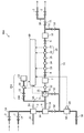
- FIG. 1 is a system diagram showing the configuration of the combustible gas concentration measuring device 99 of this embodiment.
- FIG. 2 is a block diagram showing a control flow in the combustible gas concentration measuring apparatus 99 shown in FIG.
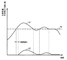
- FIG. 3 is a response diagram in the introduction of the inert gas in the combustible gas concentration measuring apparatus 99 shown in FIG.
- FIG. 4 is a schematic view showing an example in which the combustible gas concentration measuring device 99 of this embodiment is applied to an improved boiling water light water reactor.
- the combustible gas concentration measuring device 99 includes a pipe 1A, an inert gas introduction device 15, a dehumidifying device 6, a hygrometer 22, a pump 7, a pressure control valve 8, a thermometer 23, a flow meter 24, and a pressure gauge 25.
- the pipe 1A is a pipe for collecting the gas to be measured from the measurement target location so that the atmosphere in an arbitrary location can be measured.
- the pipe 1B is a pipe for transferring the gas to be measured after concentration measurement to an arbitrary place, for example, the original place.
- the flow path selection valve 2 is provided in the pipes 1A and 1B for the purpose of switching and measuring a plurality of locations.
- the number of measurement points is two.
- the pump 10 is a pump for transferring the gas to be measured collected from the pipe 1A toward the combustible gas concentration meter 28.
- the combustible gas concentration meter 28 shows an example in which a concentration meter that measures two kinds of gases is mounted.
- the combustible gas concentration meter 28 includes an oxygen concentration meter 26 and a hydrogen concentration meter 27. Yes.
- the oxygen concentration meter 26 and the hydrogen concentration meter 27 can have the same configuration as a general concentration meter.
- the oxygen concentration meter 26 includes a magnetic wind type
- the hydrogen concentration meter 27 includes a heat conduction type. It is done.
- Pressure control valves 8 and 9 are provided on the upstream and downstream sides of the combustible gas concentration meter 28. In accordance with the specifications of the combustible gas concentration meter 28 in the pipe 1A in the section between the pressure control valves 8 and 9. The pressure is adjusted to a certain level. Although the pressure depends on the specifications of the combustible gas concentration meter 28, it is normally used at about atmospheric pressure and is maintained at about 0.9 to 1.2 atm.
- the pump 7 is installed on the upstream side of the pressure control valve 8 in case the pressure at the gas collecting place is low and the pressure at the position of the combustible gas concentration meter 28 does not rise to a specified value. Then, the pressure is reduced by the pressure control valve 8 so that a specified pressure can be secured.
- the pressure gauge 25 is provided in the pipe 1A for confirming the pressure between the pressure control valves 8 and 9.
- the flow rate at the position of the combustible gas concentration meter 28 is set according to the specifications of the combustible gas concentration meter 28, but in many cases, it is required to be about 50 to 3000 cm 3 / min.
- the flow control valve 11 and the flow meter 24 are provided in the pipe 1A for setting and checking the flow rate of the gas to be measured by the combustible gas concentration meter 28.
- thermometer 23 is provided in the pipe 1A in order to grasp factors affecting the measurement of the combustible gas concentration meter 28 and to perform correction as necessary.
- the dehumidifying device 6 is a device that removes water vapor in the gas to be measured collected through the pipe 1 ⁇ / b> A, and includes a cooler 3, a steam / water separator 4, and a dehumidifier 5.
- the dehumidifying device 6 is configured so that most of the non-condensable gas, for example, hydrogen or oxygen, and a gas composed of an inert gas introduced from an inert gas introducing device 15 described later, flow in the downstream side of the dehumidifying device 6. Has been.
- the amount of water vapor is not completely zero, it is possible to remove the water vapor so as not to condense in the pipe 1A without affecting the combustible gas concentration meter 28.
- the dew point temperature is cooled to 1 to 4 ° C. in the dehumidifier 6, it is possible to reduce a sufficient amount of water vapor while preventing freezing of the water vapor. Condensation within 1A does not occur.
- the cooler 3 is, for example, a double-pipe heat exchanger, and is a device that lowers the temperature of the gas to be measured to 40 degrees or less by flowing cooling water using the cooling water pipe 61.
- the steam separator 4 is a device that removes water droplets in the gas to be measured cooled by the cooler 3.
- the dehumidifier 5 is, for example, an electrically cooled dehumidifier, and dehumidifies the gas to be measured collected so as to have a specified humidity.
- a dehumidifier outlet measuring device for measuring an index having humidity or dew point temperature or information equivalent thereto at the outlet of the dehumidifier 5.
- An example of an index having information equivalent to humidity or dew point temperature is that the dehumidifier outlet temperature when using an electrically cooled dehumidifier corresponds to the dew point temperature.
- a thermometer 21 and a hygrometer 22 are installed on the outlet (downstream) side of the dehumidifier 5 as a dehumidifier outlet measuring instrument, and either or both of the thermometer 21 and the hygrometer 22 are used. Monitors dehumidification capacity.
- thermometer 21 When the amount of water vapor in the gas to be measured exceeds the dehumidifying capacity of the dehumidifying device 6, the values of the thermometer 21 and the hygrometer 22 increase, so that the dehumidifying capacity can be monitored.
- the hygrometer 22 can be a dew point meter.
- the condensed water meter (water amount measuring unit) 54 collects and measures the condensed water dehumidified by the dehumidifying device 6 from the gas to be measured, including water vapor, via the condensed water discharge pipe 51 having an appropriate gradient. This device is provided below the dehumidifier 6 so that the condensed water falls by gravity.
- the condensate meter 54 includes a water level meter 29, and the water level change is measured by the water level meter 29 to measure the amount of condensed water generated within a specific time. The amount of condensed water measured by the water level gauge 29 is converted into the amount of water vapor at the sampling location of the gas to be measured by the controller 60 (described later).
- the condensate valve 52 When the condensate meter 54 is full, the condensate valve 52 is closed, and the condensate transfer valve 53 and the condensate discharge valve 55 are opened to discharge the condensed water using the outlet pressure of the pump 10. .
- the condensed water valve 52 When the condensed water falls to the specified water level, the condensed water valve 52 is opened, the condensed water transfer valve 53 and the condensed water discharge valve 55 are closed, and the measurement of the condensed water is started again.
- the inert gas introduction device 15 includes an inert gas cylinder 12, a flow rate controller 30, a check valve 13, and an inert gas introduction pipe.
- the inert gas introduction device 15 is connected to the upstream side of the dehumidifying device 6 in the pipe 1A, and can introduce an inert gas into the gas to be measured through the inert gas introduction pipe 14. Yes.
- the inert gas introduced by the inert gas introduction device 15 is a gas that does not chemically react with the gas to be measured.
- nitrogen gas is used, but inert gas such as argon gas or helium gas is used.
- the type is not particularly limited as long as it is present.
- a flow controller 30 is provided between the inert gas cylinder 12 of the inert gas introduction pipe 14 and the pipe 1A, and it is possible to receive an external signal and adjust the introduction amount of the inert gas to an arbitrary flow rate. It has become.
- the inert gas introduction pipe 14 is provided with a check valve 13 for preventing backflow. It has been.
- the controller 60 includes a calculation unit 62 including a first calculation device 72, a second calculation device 73, and an indicator 74, and a flow rate adjustment mechanism 71.
- the flow rate adjusting mechanism 71 is configured so that the amount of water vapor contained in the gas to be measured that has passed through the dehumidifying device 6 based on the measurement value signal output from the dehumidifier outlet measuring device (thermometer 21 and hygrometer 22) It is determined whether or not the dehumidification target value has been exceeded. When it is judged that the flow rate adjustment mechanism 71 has exceeded, the flow rate adjustment mechanism 71 outputs a control signal corresponding to the amount of the inert gas to be introduced so as to be lower than the dehumidification capacity of the dehumidifier 6 to the flow rate adjuster 30, and is inactive. Control the amount of gas introduced.
- the amount of inert gas introduced by the inert gas introduction device 15 is an amount corresponding to the excess of the dehumidifying capacity of the dehumidifying device 6. Thereby, the inert gas introduction amount is adjusted.
- the adjustment of the introduction amount is feedback controlled so that each index becomes a constant value.
- the amount of water vapor is equal to or less than the dehumidification target value, it is determined that the amount is not exceeded, and the inert gas is not introduced.
- the flow rate adjusting mechanism 71 when measuring the total steam, introduces an inert gas in the same amount as the flow rate at 28 parts of the combustible gas concentration meter because the water vapor is almost dehumidified.
- FIG. 3 is a response diagram achieved by the control of the flow rate adjusting mechanism 71 and shows an example of changes in the water vapor amount 41 and the inert gas introduction amount 42 when the inert gas is introduced.
- the flow rate adjusting mechanism 71 determines the amount of inert gas to be introduced based on the signals output from the thermometer 21 and the hygrometer 22, and the flow rate adjusting mechanism 71 passes through the dehumidifier 6.
- the inert gas introduction amount 42 is increased.
- the amount of water vapor 41 starts to decrease, so that the amount of inert gas introduced 42 is also decreased.
- the water vapor amount 41 is equal to or less than the dehumidification target value 43, no inert gas is introduced.
- thermometer 21 or the hygrometer 22 can be directly used for the information on the water vapor amount 41 used in the flow rate adjusting mechanism 71.
- the calculation unit 62 including the first calculation device 72, the second calculation device 73, and the indicator 74 calculates a concentration of the combustible gas in the gas to be measured based on the measurement value obtained by the combustible gas concentration meter 28. It is.
- the first arithmetic unit 72 and the second arithmetic unit 73 correct the amount of the inert gas introduced from the inert gas introduction device 15 when calculating the concentration of the combustible gas in the measured gas, and measure the measured gas. Calculate the concentration of flammable gas inside.
- the amount of water vapor is corrected from the measured value obtained by the combustible gas concentration meter 28 based on the amount of condensed water measured by the condensed water meter 54.
- the first arithmetic unit 72 calculates the total flow rate and the inert gas flow rate at the position of the combustible gas concentration meter 28 from the signal from the combustible gas concentration meter 28 and the signal from the inert gas flow rate controller 30.
- the concentration of the combustible gas in the gas to be measured in a state excluding the water vapor and the introduced inert gas is obtained.
- the total flow rate in the combustible gas concentration meter 28 is a flow rate adjusted to a constant value by the flow rate control valve 11 and is equal to the value of the flow meter 24.
- the concentration of the combustible gas in the state excluding the water vapor and the inert gas obtained by the calculation is output and displayed on the indicator 74.
- the signal from the flow controller 30 can be replaced by a signal from the flow controller 71.
- the calculation result of the first calculation device 72 is input to the second calculation device 73 in order to obtain the combustible gas concentration in a state containing water vapor.
- a signal of the calculation result is also output to a recorder (not shown).
- the second arithmetic unit 73 calculates the amount of water vapor from the amount of condensed water measured by the condensed water meter 54 and the water level meter 29, and measured the combustible gas. Correct the density.
- the second arithmetic unit 73 receives the calculation result signal of the combustible gas concentration in the state where water vapor is removed from the first arithmetic unit 72, the water level signal from the water level gauge 29, and the temperature signal from the thermometer 23. .
- the amount of condensed water within a certain time is measured based on the signal from the water level gauge 29, converted into a water vapor amount, and then converted into a combustible gas concentration in a state containing water vapor.
- the amount of water vapor and the combustible gas concentration in a state containing water vapor are output to the indicator 74.
- the computation result signal is also output to a recorder (not shown).
- FIG. 4 shows an example in which the combustible gas concentration measuring device 99 of this embodiment is applied to an improved boiling water light water reactor.
- the atmosphere gas as the gas to be measured is collected in the combustible gas concentration measuring device 99 using the pipe 1 ⁇ / b> A, and the combustible gas described above is collected.
- the concentration of combustible gas is measured by the gas concentration meter 28.
- the dry well 92 or the wet well 93 can be selected by switching the flow path selection valve 2.
- the measured gas after measurement can be returned to the vicinity of the location where the measured gas was collected using the pipe 1B.
- the condensed water generated by the measurement is discharged to the wet well 93 through the condensed water discharge pipe 51.
- the gas to be measured sucked by the pump 10 and the inert gas arbitrarily introduced by the inert gas introduction device 15 controlled by the controller 60 are removed from the contained water vapor when passing through the dehumidifying device 6, and the dry gas It becomes.
- the combustible gas concentration meter 28 since the concentration of oxygen or hydrogen is measured in a state where the water vapor is removed and the inert gas is contained, the water vapor and the inert gas are measured in the first arithmetic unit 72 in the controller 60.
- the flammable gas concentration in the measurement gas in a state excluding the gas is calculated, and the second calculation device 73 calculates two concentrations of the flammable gas concentration in the measurement gas in a state containing water vapor by calculation. Ask.
- the inert gas introduction device is disposed upstream of the dehumidifying device 6 including the cooler 3, the steam separator 4, and the dehumidifier 5. 15 is provided, an inert gas is introduced into the gas to be measured, and the contribution of the inert gas introduced during the calculation of the combustible gas concentration is subtracted.
- the dehumidifying capacity of the dehumidifying device 6 is increased to solve the problem.
- the dehumidifying capacity of the dehumidifying device 6 is increased to solve the problem.
- the dehumidifying capacity of the dehumidifying device 6 is increased to solve the problem.
- the dehumidifying capacity of the dehumidifying device 6 is increased to solve the problem.
- the dehumidifying capacity of the dehumidifying device 6 is increased to solve the problem.
- the dehumidifying capacity of the dehumidifying device 6 is increased to solve the problem.
- the dehumidifying capacity of the dehumidifying device 6 is increased to solve the problem.
- the combustible gas concentration in the piping downstream of the dehumidifying device 6 is increased by the amount of the removed water vapor, which increases the risk of combustion.
- the inert gas is introduced, the increase in the concentration of the combustible gas downstream of the dehumidifier 6 is suppressed, so that it is effective from the viewpoint of preventing combustion.
- cooler 3 and the steam separator 4 are provided on the downstream side of the inert gas introduction device 15 and the upstream side of the dehumidifier 5, the introduced inert gas and the gas to be measured are sufficiently mixed. Therefore, more stable measurement of combustible gas concentration is possible.
- the flow rate adjusting mechanism 71 is provided to control the amount of inert gas introduced so that unnecessary inert gas can be removed. In addition to eliminating the need for introduction, it is possible to introduce a stable inert gas in accordance with the change in the amount of water vapor in the gas to be measured, thereby enabling more stable measurement of the combustible gas concentration.
- a condensate meter 54 that measures the amount of condensed water dehumidified from the gas to be measured is provided, and the combustible gas concentration meter is based on the amount of condensed water measured by the condensate meter 54 in the computing unit 62. By correcting the amount of water vapor from the measurement value obtained at 28, it becomes possible to obtain a more accurate combustible gas concentration.
- the calculation process is performed on the assumption that the flow rate of the gas to be measured in the combustible gas concentration meter 28 is fixed and the flow rate information is stored in the first calculation device 72 in advance.
- the flow control valve 11 can be used as the flow controller 30, and the signal from the flow meter 24 can be input to the second arithmetic unit 73.
- the flow rate of the combustible gas concentration meter 28 can be made variable. it can.
- Example 2 of the combustible gas concentration measuring apparatus and combustible gas concentration measuring method of the present invention will be described with reference to FIG.
- the same components as those in FIGS. 1 to 4 are denoted by the same reference numerals, and description thereof is omitted. The same applies to the following embodiments.
- the inert gas is introduced from the upstream side of the dehumidifier 6.
- the inert gas is introduced from the upstream side of the dehumidifier 6.
- the inert gas introducing device 15A is connected to the pipe 1A in the middle of the dehumidifying device 6. That is, the cooler 3 and the steam / water separator 4 are provided on the upstream side of the connection portion between the inert gas introduction pipe 14A and the pipe 1A of the inert gas introduction device 15A.
- the combustible gas concentration measuring device 99A of the present embodiment has the same configuration and operation as the configuration and operation of the combustible gas concentration measuring device 99 of the first embodiment described above except for the inert gas introduction device 15A and the dehumidifying device 6A. The configuration is omitted here.
- the cooler 3 and the steam / water separator 4 on the upstream side of the inert gas introduction device 15, the cooler that takes time for the inert gas introduction location to pass through the dehumidifier of the gas to be measured. Therefore, the responsiveness can be increased compared to the apparatus of the first embodiment, and the concentration of the combustible gas can be measured more accurately.
- the application location of the combustible gas concentration measuring device and the combustible gas concentration measuring method of the present invention is not limited to the light water reactor. It can be applied to a location where the concentration of combustible gas in an atmosphere containing water vapor and combustible gas is measured.
- Water level meter 30 ... Flow rate controller 41 ... Water vapor amount 42 ... Inert gas introduction amount 43 ... Dehumidification target value 51 ... Condensate discharge pipe 52 ... Condensed water valve 53 ... Condensed water transfer valve 54 ... Condensed water meter (water volume measuring unit) 55 ... Condensate discharge valve 60 ... Controller 61 ... Cooling water pipe 62 ... Calculation unit 71 ... Flow rate adjusting mechanism 72 ... First calculation device 73 ... Second calculation device 74 ... Indicator 91 ... Reactor containment vessel 92 ... Dry well 93 ... Wetwell 99, 99A ... Combustible gas concentration measuring device
Landscapes
- Chemical & Material Sciences (AREA)
- Life Sciences & Earth Sciences (AREA)
- Physics & Mathematics (AREA)
- Health & Medical Sciences (AREA)
- Immunology (AREA)
- Analytical Chemistry (AREA)
- Biochemistry (AREA)
- General Health & Medical Sciences (AREA)
- General Physics & Mathematics (AREA)
- Pathology (AREA)
- Electrochemistry (AREA)
- Chemical Kinetics & Catalysis (AREA)
- Engineering & Computer Science (AREA)
- Plasma & Fusion (AREA)
- General Engineering & Computer Science (AREA)
- High Energy & Nuclear Physics (AREA)
- Hydrology & Water Resources (AREA)
- Biomedical Technology (AREA)
- Molecular Biology (AREA)
- Monitoring And Testing Of Nuclear Reactors (AREA)
- Sampling And Sample Adjustment (AREA)
- Investigating Or Analyzing Materials Using Thermal Means (AREA)
Abstract
冷却器3や気水分離器4、除湿器5からなる除湿装置6の上流、若しくは除湿装置6Aの途中である冷却器3や気水分離器4の下流かつ除湿器5の上流に不活性ガス導入装置15,15Aを設けて、被測定ガスに対して不活性ガスを導入し、可燃性ガス濃度の演算時に導入した不活性ガスの寄与を差し引く。これにより、被測定ガス中の水蒸気の含有量に依存せず、可燃性ガス濃度を測定することができる可燃性ガス濃度測定装置および可燃性ガス濃度測定方法が提供される。
Description
本発明は、可燃性ガス濃度測定装置および可燃性ガス濃度測定方法に関する。
水蒸気を含む雰囲気の水素または酸素濃度を測定する装置において、除湿によって発生する測定誤差を補正する機能を設け、正しい測定値を得ることを目的とした原子炉格納容器内雰囲気モニタが特許文献1に記載されている。
この特許文献1には、ガス中の水素または酸素濃度を測定するセンサとの間に配置された除湿器の上流側に流量、圧力、温度測定器または除湿器にドレン流量測定器を設け、かつ、除湿器の下流側に流量、圧力、温度測定器を設け、これら測定器で測定した信号を取り込んで除湿器の除湿作用によって蒸気分が消失したことによるモル減衰率を求めるとともに、このモル減衰率を用いてセンサの水素または酸素濃度測定値を補正することが記載されている。
可燃性の気体が存在する雰囲気では、爆発、爆轟を含む燃焼を防ぐために、種々の安全対策が講じられている。このような可燃性の気体が存在する雰囲気の状態を適切に把握するために、可燃性気体の検知器や濃度計が設置されている。
設置される濃度計には測定精度を保証する条件があり、被測定雰囲気が高温の場合や水蒸気を含む場合には、条件を逸脱することがある。そのような場合、被測定雰囲気中の可燃性ガスの濃度を正確に測定するためには、被測定ガスを冷却かつ除湿し、濃度計の仕様に合致した条件の気体とする必要がある。
上述した特許文献1には、水蒸気を含む雰囲気において、水素または酸素濃度を測定するためにセンサ上流に除湿器が備えられた装置が記載されている。しかし、特許文献1に記載された装置では、除湿器の除湿能力を超過する水蒸気量を含むガスを測定することができない、との問題があった。
例えば、全蒸気を測定する場合、除湿器の下流側に流れるべき非凝縮性ガス、例えば水素や酸素が存在しないにもかかわらず、ポンプにより強制的にガスを吸引することになり、水蒸気が除湿器下流に流れることとなる。この時、水素または酸素濃度計が正常な値を示さないばかりか、水蒸気が配管内で結露し、やがて配管内に水が溜まり、測定が不可能となる。
本発明の目的は、被測定ガス中の水蒸気の含有量に依存せず、可燃性ガス濃度を測定することができる可燃性ガス濃度測定装置および可燃性ガス濃度測定方法を提供することにある。
上記課題を解決するために、例えば特許請求の範囲に記載の構成を採用する。
本発明は、上記課題を解決する手段を複数含んでいるが、その一例を挙げるならば、水蒸気を含む被測定ガスに含まれる可燃性ガスの濃度を測定するための可燃性ガス濃度測定装置であって、前記可燃性ガスの濃度を測定する濃度測定部と、この濃度測定部の上流側に設けられ、前記濃度測定部に送る前記被測定ガス中の水蒸気を除去する除湿器と、この除湿器の上流側に設けられ、前記除湿器に供給される前記被測定ガスに不活性ガスを導入する不活性ガス導入部と、前記濃度測定部で得られる測定値に基づいて前記被測定ガス中の前記可燃性ガスの濃度を演算する演算部と、を備え、前記演算部は、前記被測定ガス中の前記可燃性ガスの濃度を演算する際に前記不活性ガス導入部から導入された不活性ガスの量を補正することを特徴とする。
本発明は、上記課題を解決する手段を複数含んでいるが、その一例を挙げるならば、水蒸気を含む被測定ガスに含まれる可燃性ガスの濃度を測定するための可燃性ガス濃度測定装置であって、前記可燃性ガスの濃度を測定する濃度測定部と、この濃度測定部の上流側に設けられ、前記濃度測定部に送る前記被測定ガス中の水蒸気を除去する除湿器と、この除湿器の上流側に設けられ、前記除湿器に供給される前記被測定ガスに不活性ガスを導入する不活性ガス導入部と、前記濃度測定部で得られる測定値に基づいて前記被測定ガス中の前記可燃性ガスの濃度を演算する演算部と、を備え、前記演算部は、前記被測定ガス中の前記可燃性ガスの濃度を演算する際に前記不活性ガス導入部から導入された不活性ガスの量を補正することを特徴とする。
本発明によれば、水蒸気の含有量に依存せず、可燃性ガスの濃度を測定することができる。上記した以外の課題、構成および効果は、以下の実施例の説明により明らかにされる。
以下に本発明の可燃性ガス濃度測定装置および可燃性ガス濃度測定方法の実施例を、図面を用いて説明する。
<実施例1>
本発明の可燃性ガス濃度測定装置および可燃性ガス濃度測定方法の実施例1を、図1乃至図4を用いて説明する。なお、図1乃至図4においては、可燃性ガス濃度測定装置を改良型沸騰水型軽水炉に適用し、測定する対象の可燃性ガスを水素および酸素とした場合を例に挙げて説明する。
本発明の可燃性ガス濃度測定装置および可燃性ガス濃度測定方法の実施例1を、図1乃至図4を用いて説明する。なお、図1乃至図4においては、可燃性ガス濃度測定装置を改良型沸騰水型軽水炉に適用し、測定する対象の可燃性ガスを水素および酸素とした場合を例に挙げて説明する。
図1は、本実施例の可燃性ガス濃度測定装置99の構成を示す系統図である。図2は、図1に示す可燃性ガス濃度測定装置99における制御の流れを示すブロック図である。図3は、図2に示す可燃性ガス濃度測定装置99における不活性ガスの導入における応答図である。図4は、本実施例の可燃性ガス濃度測定装置99を改良型沸騰水型軽水炉に適用した例を示す概略図である。
図1において、可燃性ガス濃度測定装置99は、配管1A、不活性ガス導入装置15、除湿装置6、湿度計22、ポンプ7、圧力調節弁8、温度計23、流量計24、圧力計25、可燃性ガス濃度計28、圧力調節弁9、ポンプ10、流量調節弁11、配管1B、凝縮水排出用配管51、凝縮水計量器54、コントローラ60を備えている。
配管1Aは、任意の場所の雰囲気を測定できるよう、測定対象箇所から被測定ガスを採取するための配管である。
配管1Bは、濃度測定後の被測定ガスを任意の場所、例えば元の場所へと移送するための配管である。
流路選択弁2は、複数の場所を切り替えて測定することを目的として配管1A,1Bに設けられている。図1では、測定箇所を2箇所とした。
ポンプ10は、配管1Aから採取した被測定ガスを可燃性ガス濃度計28に向けて移送するためのポンプである。
図1において、可燃性ガス濃度計28は2種類のガスを測定する濃度計を搭載した例を示しており、可燃性ガス濃度計28は酸素濃度計26と水素濃度計27とで構成されている。酸素濃度計26や水素濃度計27は一般的な濃度計と同じ構成とすることができ、例えば酸素濃度計26であれば磁気風式等、水素濃度計27であれば熱伝導式等が挙げられる。
この可燃性ガス濃度計28の上下流には圧力調節弁8,9が設けられており、この圧力調節弁8,9の間の区間の配管1A中で可燃性ガス濃度計28の仕様に合わせて圧力が一定に調節される。圧力は可燃性ガス濃度計28の仕様によるが、通常は大気圧程度で使用され、0.9~1.2気圧程度に保持される。
ポンプ7は、ガス採取場所の圧力が低く、可燃性ガス濃度計28の位置の圧力が規定の値まで上がらない場合に備えて圧力調節弁8の上流側に設置されており、一旦圧力を上昇させた後、圧力調節弁8で減圧することにより、規定の圧力を確保できるようになっている。
圧力計25は、圧力調節弁8,9の間の圧力を確認するために配管1Aに備えられている。
可燃性ガス濃度計28の位置での流量は、可燃性ガス濃度計28の仕様に合わせて設定されるが、多くの場合、50~3000cm3/min程度であることが求められる。流量調節弁11および流量計24は、この可燃性ガス濃度計28での被測定ガスの流量の設定と確認のために配管1Aに備えられている。
温度計23は、可燃性ガス濃度計28の測定に影響を与える因子を把握し、必要に応じて補正を施すために配管1Aに備えられている。
除湿装置6は、配管1Aを介して採取された被測定ガス中の水蒸気を除去する装置であり、冷却器3、気水分離器4、除湿器5から構成される。この除湿装置6下流側には、ほとんどが非凝縮性ガス、例えば、その成分のほとんどが水素や酸素、後述する不活性ガス導入装置15から導入された不活性ガスからなるガスが流れるように構成されている。水蒸気の量は完全に零とはならないが、可燃性ガス濃度計28に影響を与えず、配管1A内で凝結しない条件まで除去することが可能である。例えば、除湿装置6において露点温度を1~4℃まで冷却すると、水蒸気の凍結を防ぎつつ、十分な量の水蒸気を低減させることが可能であり、一般的な測定装置周囲の温度より低く、配管1A内での凝結は生じない。
冷却器3は、例えば二重管式熱交換器であり、冷却水配管61を利用して冷却水を流すことにより被測定ガスの温度を40度以下まで低下させる機器である。
気水分離器4は、冷却器3で冷却された被測定ガス中の水滴を除去する機器である。
除湿器5は例えば電気冷却式除湿器であり、規定の湿度となるよう採取した被測定ガスの除湿を行う。
除湿装置6の除湿能力を監視するために、除湿器5出口において湿度または露点温度もしくはそれらと同等の情報を有している指標を測定するための除湿器出口計測器が設けられている。湿度又は露点温度と同等の情報を有している指標の例としては、電気冷却式除湿器を使用した場合の除湿器出口温度が露点温度に相当していることが挙げられる。本実施例では、除湿器出口計測器として、除湿器5の出口(下流)側に温度計21および湿度計22が設置されており、これら温度計21および湿度計22の両方もしくはどちらか一方によって除湿能力を監視している。被測定ガス中の水蒸気量が除湿装置6での除湿能力を超過すると、温度計21および湿度計22の値が上昇するため、除湿能力を監視することが可能となっている。なお、湿度計22は露点計を用いることができる。
凝縮水計量器(水量測定部)54は、水蒸気を含む被測定ガスから除湿装置6によって除湿された凝縮水を、適切に勾配をつけた凝縮水排出用配管51を介して集め、計量するための機器であり、凝縮水が重力落下するよう除湿装置6の下方に設けられている。凝縮水計量器54は水位計29を備えており、水位計29によって水位変化を測定し、ある特定の時間内に発生した凝縮水量を測定する。水位計29で測定された凝縮水量は、被測定ガスの採取箇所における水蒸気の量へとコントローラ60(後述)において換算処理される。凝縮水計量器54が満水になると、凝縮水弁52を閉止し、凝縮水移送弁53、凝縮水排出弁55を開放することで、ポンプ10の出口圧力を利用して、凝縮水を排出する。凝縮水が規定の水位まで低下すると、凝縮水弁52を開放し、凝縮水移送弁53、凝縮水排出弁55を閉止し、再度凝縮水の計量を開始する。
不活性ガス導入装置15は、不活性ガスボンベ12、流量調節器30、逆止弁13、不活性ガス導入用配管14から構成される。不活性ガス導入装置15は、配管1Aの除湿装置6の上流側に接続されており、不活性ガス導入用配管14を通じて被測定ガスに対して不活性ガスを導入することができるようになっている。不活性ガス導入装置15により導入する不活性ガスは、被測定対象のガスと化学的に反応しないガスであり、例えば窒素ガスが使用されるが、アルゴンガスやヘリウムガスなど、不活性なガスであれば特にその種類は限定されない。
不活性ガス導入用配管14の不活性ガスボンベ12から配管1Aまでの間に流量調節器30が設けられており、外部信号を受けて不活性ガスの導入量を任意の流量に調節することが可能となっている。
不活性ガスを導入するためには、不活性ガスの圧力が被測定ガスの圧力より高くなければならないため、不活性ガス導入用配管14には、逆流を防止するための逆止弁13が設けられている。
コントローラ60は、図2に示すように、第1演算装置72、第2演算装置73および指示計74からなる演算部62と、流量調節機構71とから構成されている。
流量調節機構71は、除湿器出口計測器(温度計21および湿度計22)から出力される測定値信号に基づいて除湿装置6を通過した被測定ガスに含まれる水蒸気量が、除湿装置6の除湿目標値を超過したか否かを判断する。流量調節機構71は、超過していると判断されたときは除湿装置6の除湿能力を下回るように導入すべき不活性ガスの量に応じた制御信号を流量調節器30に出力し、不活性ガスの導入量を制御する。不活性ガス導入装置15による不活性ガスの導入量は、除湿装置6の除湿能力の超過分に応じた量とする。これにより、不活性ガス導入量を調節している。導入量の調節は各指標が一定値となるようにフィードバック制御される。これに対し、水蒸気量が除湿目標値以下の場合は超過していないと判断し、不活性ガスは導入しない。
また、流量調節機構71は、全蒸気を測定する場合は、水蒸気がほとんど除湿されることから、可燃性ガス濃度計28部での流量と同量の不活性ガスを導入する。
流量調節機構71における制御の具体例について図3を参照して以下説明する。図3は流量調節機構71の制御により達成される応答図であり、不活性ガス導入時の水蒸気量41と不活性ガス導入量42の変化の例を示している。
図3に示すように、流量調節機構71は、温度計21と湿度計22とから出力される信号に基づいて導入すべき不活性ガスの量を判定しており、除湿装置6を通過した被測定ガスに含まれる水蒸気量41が、除湿装置6の除湿目標値43を超過したと判断されるときは、不活性ガス導入量42を大きくする。十分な量の不活性ガスが導入されると水蒸気量41は減少に転じるので、不活性ガス導入量42も減少させる。水蒸気量41が除湿目標値43以下の場合は、不活性ガスは導入しない。
なお、この流量調節機構71で用いる水蒸気量41の情報は、温度計21や湿度計22の出力値を直接利用することができる。
第1演算装置72、第2演算装置73および指示計74からなる演算部62は、可燃性ガス濃度計28で得られる測定値に基づいて被測定ガス中の可燃性ガスの濃度を演算する部分である。
第1演算装置72や第2演算装置73では、被測定ガス中の可燃性ガスの濃度を演算する際に不活性ガス導入装置15から導入された不活性ガスの量を補正して被測定ガス中の可燃性ガスの濃度を演算する。
第2演算装置73では、凝縮水計量器54で測定された凝縮水の量に基づいて、可燃性ガス濃度計28で得られる測定値から水蒸気量を補正する。
以下、第1演算装置72や第2演算装置73における演算処理についてより具体的に説明する。
第1演算装置72では、可燃性ガス濃度計28の信号と不活性ガスの流量調節器30からの信号とから、可燃性ガス濃度計28の位置における全流量と不活性ガスの流量を求める演算処理を行うことで、水蒸気および導入した不活性ガスを除いた状態での被測定ガス中の可燃性ガス濃度を求める。可燃性ガス濃度計28部における全流量は、流量調節弁11で一定値に調節された流量であり、流量計24の値と等しい。演算により求められた水蒸気および不活性ガスを除いた状態での可燃性ガス濃度は指示計74に出力・表示される。なお、流量調節器30からの信号は、流量調節機構71からの信号でも代替できる。
水蒸気を含んだ状態での可燃性ガス濃度を求めるため、第1演算装置72の演算結果が第2演算装置73に入力される。演算により求められた水蒸気を除いた状態での可燃性ガス濃度を記録する場合には、記録計(不図示)に対しても演算結果の信号を出力する。
水蒸気を含んだ状態での可燃性ガス濃度を求めるために、第2演算装置73は、凝縮水計量器54と水位計29で計量された凝縮水量から水蒸気量を逆算し、測定した可燃性ガス濃度を補正する。
第2演算装置73には、第1演算装置72から水蒸気を除いた状態での可燃性ガス濃度の演算結果信号、水位計29からの水位信号、温度計23からの温度信号が入力されている。第2演算装置73では、水位計29の信号を元に、一定時間内の凝縮水量を測定し、水蒸気量に換算した後、水蒸気を含んだ状態での可燃性ガス濃度へと換算する。水蒸気量と水蒸気を含んだ状態での可燃性ガス濃度は指示計74へ出力される。
上述の演算により求められた水蒸気を含んだ状態での可燃性ガス濃度や水蒸気量を記録する場合には、記録計(不図示)に対しても演算結果の信号を出力する。
本実施例の可燃性ガス濃度測定装置99を改良型沸騰水型軽水炉に適用した例を図4に示す。
図4において、原子炉格納容器91内の可燃性ガス濃度を測定するために、被測定ガスである雰囲気ガスを配管1Aを使って可燃性ガス濃度測定装置99内に採取し、上記した可燃性ガス濃度計28により可燃性ガスの濃度の測定を行う。
濃度の測定場所は、流路選択弁2の切り替えによりドライウェル92もしくはウェットウェル93を選択することができるようになっている。
測定後の被測定ガスは、配管1Bを使用して、被測定ガスを採取した場所付近へ戻すことができる。
測定により発生した凝縮水は、凝縮水排出用配管51を通ってウェットウェル93へ排出される。
次に、以上のように構成された本実施例にかかる可燃性ガス濃度測定装置99を使用した実際の可燃性ガスの濃度の測定について説明する。
ポンプ10により吸引された被測定ガスと、コントローラ60によって制御された不活性ガス導入装置15により任意に導入された不活性ガスは、除湿装置6を通過する際に含有水蒸気が除去され、乾燥ガスとなる。
乾燥ガスとなった後、ポンプ7、圧力調節弁8等を通過し、可燃性ガス濃度計28の酸素濃度計26によって酸素濃度が、水素濃度計27によって水素濃度が測定される。
可燃性ガス濃度計28では、水蒸気が除去されて不活性ガスが含まれた状態での酸素または水素の濃度が測定されているため、コントローラ60中の第1演算装置72において水蒸気および不活性ガスを除いた状態での被測定ガス中の可燃性ガス濃度を演算し、また第2演算装置73において水蒸気を含んだ状態での被測定ガス中の可燃性ガス濃度の2種類の濃度を演算により求める。
次に、本実施例の効果について説明する。
上述した本発明の可燃性ガス濃度測定装置および可燃性ガス濃度測定方法の実施例1では、冷却器3や気水分離器4、除湿器5からなる除湿装置6の上流に不活性ガス導入装置15を設けて、被測定ガスに対して不活性ガスを導入し、可燃性ガス濃度の演算時に導入した不活性ガスの寄与を差し引くこととしている。
これによって、除湿装置6の除湿能力以上の水蒸気を含む被測定ガス中の可燃性ガスの濃度を連続的に測定することが可能となる。
通常、除湿能力が不足する場合は、除湿装置6の除湿能力を増加させて解決する。例えば、冷却器3に二重管式熱交換器を使用している場合、規定の温度までガスを冷却するためには、冷却器の伝熱面積を増やす必要がある。しかし、伝熱面積を増やすと、ガスが冷却器を通過するのに要する時間が長くなるため、ガスが可燃性ガス濃度計28に到達するまでの時間が長くなる。従って、指示計74で可燃性ガス濃度を確認できるまでの遅れ時間が長くなる。しかし、本実施例であれば、不活性ガスを導入することから、冷却器を増やす必要がなくなる。よって、遅れ時間を悪化させることなく被測定ガス中の可燃性ガスの濃度を測定することができる。
また、可燃性ガス濃度が高い場合は、燃焼の恐れが生じる。そのため、何も対策を取らずに除湿装置6により水蒸気を除去すると、除湿装置6下流の配管内では、除去された水蒸気の分だけ可燃性ガス濃度が高くなり、燃焼の危険性が増すことになる。しかしながら本実施例では不活性ガスを導入するため、除湿装置6下流での可燃性ガス濃度が高くなることが抑制されるため、燃焼防止の観点からも有効である、との効果を奏する。
このような本実施例の可燃性ガス濃度測定装置や可燃性ガス濃度測定方法を原子炉に適用することにより、原子燃料の破損を伴う重大事故時のような大量の水蒸気を含む場合であっても、原子炉格納容器91内の可燃性ガス濃度を連続的に測定することが可能となる。
また、不活性ガス導入装置15の下流側かつ除湿器5の上流側に、冷却器3および気水分離器4を備えたため、導入される不活性ガスと被測定ガスとの混合が充分に行われ、より安定した可燃性ガス濃度の測定が可能となる。
更に、除湿装置6の下流側に設けられた温度計21および湿度計22と、温度計21および湿度計22から出力される測定値に基づいて除湿装置6における水蒸気の除湿能力を超過したか否かを判断し、超過していると判断されたときは除湿器5の除湿能力を下回るように不活性ガスの導入量を制御する流量調節機構71を備えたことで、不要な不活性ガスの導入を行う必要がなくなるとともに、被測定ガス中の水蒸気量の変化に応じた安定した不活性ガスの導入が可能となるため、より安定した可燃性ガス濃度の測定が可能となる。
また、被測定ガスから除湿された凝縮水の量を測定する凝縮水計量器54を備え、演算部62において凝縮水計量器54で測定された凝縮水の量に基づいて、可燃性ガス濃度計28で得られる測定値から水蒸気量を補正することにより、より正確な可燃性ガス濃度を求めることが可能となる。
なお、本実施例では、可燃性ガス濃度計28の部分における被測定ガスの流量は固定であり、第1演算装置72にはあらかじめ流量情報が記憶されている、と仮定して演算処理を行っている。しかし、流量調節弁11を流量調節器30とし、流量計24の信号を第2演算装置73に入力することもでき、この場合には可燃性ガス濃度計28部の流量を可変とすることができる。
<実施例2>
本発明の可燃性ガス濃度測定装置および可燃性ガス濃度測定方法の実施例2を図5を用いて説明する。図1乃至図4と同じ構成には同一の符号を示し、説明は省略する。以下の実施例においても同様とする。
本発明の可燃性ガス濃度測定装置および可燃性ガス濃度測定方法の実施例2を図5を用いて説明する。図1乃至図4と同じ構成には同一の符号を示し、説明は省略する。以下の実施例においても同様とする。
上述の実施例1では、不活性ガスを除湿装置6の上流側から導入している。例えば、図1の例では、冷却器3に二重管式熱交換器を使用すると、不活性ガスが熱交換器中を移送される時間が長くなる。このため、除湿装置6出口において除湿装置6の除湿能力の超過を測定し、不活性ガスの導入量のフィードバック制御を行っても、実際に不活性ガスが導入されて効果が現れ始めるまでに一定の時間遅れ44がある程度はどうしても生じてしまう。また、この時間遅れ44は、第1演算装置72,第2演算装置73で可燃性ガス濃度の演算を行う際に誤差の要因となりかねない。
これに対し、図5に示す本実施例の可燃性ガス濃度測定装置99Aでは、不活性ガス導入装置15Aを除湿装置6の途中にて配管1Aに接続されている。つまり、不活性ガス導入装置15Aの不活性ガス導入用配管14Aと配管1Aとの接続部分の上流側に、冷却器3および気水分離器4を設けている。
なお、本実施例の可燃性ガス濃度測定装置99Aは、不活性ガス導入装置15Aと除湿装置6A以外の構成、動作は前述した実施例1の可燃性ガス濃度測定装置99の構成、動作と同じ構成であり、詳細は省略する。
本発明の可燃性ガス濃度測定装置および可燃性ガス濃度測定方法の実施例2においても、前述した可燃性ガス濃度測定装置および可燃性ガス濃度測定方法の実施例1とほぼ同様な効果が得られる。
また、不活性ガス導入装置15の上流側に、冷却器3および気水分離器4を備えたことにより、不活性ガスの導入場所が、被測定ガスの除湿装置の通過に時間を要する冷却器3の下流となり、実施例1の装置に比べて応答性を速くすることができ、より正確な可燃性ガスの濃度測定が可能となる。
<その他>
なお、本発明は、上記の実施例に限定されるものではなく、様々な変形例が含まれる。上記の実施例は本発明を分かりやすく説明するために詳細に説明したものであり、必ずしも説明した全ての構成を備えるものに限定されるものではない。また、ある実施例の構成の一部を他の実施例の構成に置き換えることも可能であり、また、ある実施例の構成に他の実施例の構成を加えることも可能である。また、各実施例の構成の一部について、他の構成の追加・削除・置換をすることも可能である。
なお、本発明は、上記の実施例に限定されるものではなく、様々な変形例が含まれる。上記の実施例は本発明を分かりやすく説明するために詳細に説明したものであり、必ずしも説明した全ての構成を備えるものに限定されるものではない。また、ある実施例の構成の一部を他の実施例の構成に置き換えることも可能であり、また、ある実施例の構成に他の実施例の構成を加えることも可能である。また、各実施例の構成の一部について、他の構成の追加・削除・置換をすることも可能である。
例えば、可燃性ガス濃度測定装置99を改良型沸騰水型軽水炉に適用した場合について説明したが、本発明の可燃性ガス濃度測定装置および可燃性ガス濃度測定方法の適用箇所は軽水炉に限定されず、水蒸気および可燃性ガスを含んだ雰囲気における可燃性ガスの濃度を測定する箇所に適用することが可能である。
1A…配管
1B…配管
2…流路選択弁
3…冷却器
4…気水分離器
5…除湿器
6,6A…除湿装置
7…ポンプ
8,9…圧力調節弁
10…ポンプ
11…流量調節弁
12…不活性ガスボンベ
13…逆止弁
14,14A…不活性ガス導入用配管
15,15A…不活性ガス導入装置
21…温度計
22…湿度計
23…温度計
24…流量計
25…圧力計
26…酸素濃度計
27…水素濃度計
28…可燃性ガス濃度計
29…水位計
30…流量調節器
41…水蒸気量
42…不活性ガス導入量
43…除湿目標値
51…凝縮水排出用配管
52…凝縮水弁
53…凝縮水移送弁
54…凝縮水計量器(水量測定部)
55…凝縮水排出弁
60…コントローラ
61…冷却水配管
62…演算部
71…流量調節機構
72…第1演算装置
73…第2演算装置
74…指示計
91…原子炉格納容器
92…ドライウェル
93…ウェットウェル
99,99A…可燃性ガス濃度測定装置
1B…配管
2…流路選択弁
3…冷却器
4…気水分離器
5…除湿器
6,6A…除湿装置
7…ポンプ
8,9…圧力調節弁
10…ポンプ
11…流量調節弁
12…不活性ガスボンベ
13…逆止弁
14,14A…不活性ガス導入用配管
15,15A…不活性ガス導入装置
21…温度計
22…湿度計
23…温度計
24…流量計
25…圧力計
26…酸素濃度計
27…水素濃度計
28…可燃性ガス濃度計
29…水位計
30…流量調節器
41…水蒸気量
42…不活性ガス導入量
43…除湿目標値
51…凝縮水排出用配管
52…凝縮水弁
53…凝縮水移送弁
54…凝縮水計量器(水量測定部)
55…凝縮水排出弁
60…コントローラ
61…冷却水配管
62…演算部
71…流量調節機構
72…第1演算装置
73…第2演算装置
74…指示計
91…原子炉格納容器
92…ドライウェル
93…ウェットウェル
99,99A…可燃性ガス濃度測定装置
Claims (8)
- 水蒸気を含む被測定ガスに含まれる可燃性ガスの濃度を測定するための可燃性ガス濃度測定装置であって、
前記可燃性ガスの濃度を測定する濃度測定部と、
この濃度測定部の上流側に設けられ、前記濃度測定部に送る前記被測定ガス中の水蒸気を除去する除湿器と、
この除湿器の上流側に設けられ、前記除湿器に供給される前記被測定ガスに不活性ガスを導入する不活性ガス導入部と、
前記濃度測定部で得られる測定値に基づいて前記被測定ガス中の前記可燃性ガスの濃度を演算する演算部と、を備え、
前記演算部は、前記被測定ガス中の前記可燃性ガスの濃度を演算する際に前記不活性ガス導入部から導入された不活性ガスの量を補正する
ことを特徴とする可燃性ガス濃度測定装置。 - 請求項1に記載の可燃性ガス濃度測定装置において、
前記不活性ガス導入部の下流側かつ前記除湿器の上流側に、冷却器および気水分離器を更に備えた
ことを特徴とする可燃性ガス濃度測定装置。 - 請求項1に記載の可燃性ガス濃度測定装置において、
前記不活性ガス導入部の上流側に、冷却器および気水分離器を更に備えた
ことを特徴とする可燃性ガス濃度測定装置。 - 請求項1に記載の可燃性ガス濃度測定装置において、
前記除湿器の下流側に設けられた除湿器出口計測器と、
この除湿器出口計測器から出力される測定値に基づいて前記除湿器における水蒸気の除湿能力を超過したか否かを判断し、超過していると判断されたときは前記除湿器の除湿能力を下回るように前記不活性ガスの導入量を制御する制御部と、を更に備えた
ことを特徴とする可燃性ガス濃度測定装置。 - 請求項1に記載の可燃性ガス濃度測定装置において、
前記被測定ガスから除湿された凝縮水の量を測定する水量測定部を更に備え、
前記演算部は、前記水量測定部で測定された凝縮水の量に基づいて、前記濃度測定部で得られる測定値から水蒸気量を補正する
ことを特徴とする可燃性ガス濃度測定装置。 - 請求項1に記載の可燃性ガス濃度測定装置において、
前記被測定ガスは、原子炉格納容器内の雰囲気ガスである
ことを特徴とする可燃性ガス濃度測定装置。 - 水蒸気を含む被測定ガスに含まれる可燃性ガスの濃度を測定する可燃性ガス濃度測定方法であって、
測定対象のガス中の水蒸気を除湿器で除湿する除湿工程と、
この除湿工程後のガスの可燃性ガスの濃度を演算する演算工程とを有し、
前記除湿工程では、前記除湿器での除湿能力に応じて不活性ガスを前記除湿器の上流側で前記被測定ガスに導入し、
前記演算工程では、導入された不活性ガスの量を補正する
ことを特徴とする可燃性ガス濃度測定方法。 - 請求項7に記載の可燃性ガス濃度測定方法において、
前記被測定ガスは、原子炉格納容器内の雰囲気ガスである
ことを特徴とする可燃性ガス濃度測定方法。
Applications Claiming Priority (2)
| Application Number | Priority Date | Filing Date | Title |
|---|---|---|---|
| JP2016-101758 | 2016-05-20 | ||
| JP2016101758A JP6664276B2 (ja) | 2016-05-20 | 2016-05-20 | 可燃性ガス濃度測定装置および可燃性ガス濃度測定方法 |
Publications (1)
| Publication Number | Publication Date |
|---|---|
| WO2017199650A1 true WO2017199650A1 (ja) | 2017-11-23 |
Family
ID=60325388
Family Applications (1)
| Application Number | Title | Priority Date | Filing Date |
|---|---|---|---|
| PCT/JP2017/015030 Ceased WO2017199650A1 (ja) | 2016-05-20 | 2017-04-12 | 可燃性ガス濃度測定装置および可燃性ガス濃度測定方法 |
Country Status (2)
| Country | Link |
|---|---|
| JP (1) | JP6664276B2 (ja) |
| WO (1) | WO2017199650A1 (ja) |
Cited By (3)
| Publication number | Priority date | Publication date | Assignee | Title |
|---|---|---|---|---|
| CN110763803A (zh) * | 2019-11-12 | 2020-02-07 | 福州高新区玲富科技有限公司 | 一种爆破工程用的环境安全检查设备 |
| CN111929420A (zh) * | 2020-07-07 | 2020-11-13 | 中煤陕西榆林能源化工有限公司 | 一种蒸汽中可燃气体的测量方法及测量装置 |
| WO2026018550A1 (ja) * | 2024-07-19 | 2026-01-22 | パナソニックIpマネジメント株式会社 | ガス検出装置及びガス検出方法 |
Families Citing this family (1)
| Publication number | Priority date | Publication date | Assignee | Title |
|---|---|---|---|---|
| KR102725866B1 (ko) * | 2021-12-29 | 2024-11-04 | 한화오션 주식회사 | 선박의 암모니아 샘플링라인의 수분 및 산소 제거시스템 및 그 방법 |
Citations (6)
| Publication number | Priority date | Publication date | Assignee | Title |
|---|---|---|---|---|
| JPS5625250U (ja) * | 1979-08-06 | 1981-03-07 | ||
| JPS56164994A (en) * | 1980-05-24 | 1981-12-18 | Tokyo Shibaura Electric Co | Gas concentration measuring device |
| JPS574587A (en) * | 1980-06-10 | 1982-01-11 | Tokyo Shibaura Electric Co | Atmosphere monitor in nuclear reactor container |
| JPS60187893A (ja) * | 1984-03-08 | 1985-09-25 | 東京電力株式会社 | ガス濃度測定装置 |
| JPS6115539U (ja) * | 1984-07-04 | 1986-01-29 | 出光石油化学株式会社 | ガス検知器に用いる処理装置 |
| JPH03188397A (ja) * | 1989-12-19 | 1991-08-16 | Toshiba Corp | 原子炉格納容器内の水素および酸素測定装置 |
-
2016
- 2016-05-20 JP JP2016101758A patent/JP6664276B2/ja active Active
-
2017
- 2017-04-12 WO PCT/JP2017/015030 patent/WO2017199650A1/ja not_active Ceased
Patent Citations (6)
| Publication number | Priority date | Publication date | Assignee | Title |
|---|---|---|---|---|
| JPS5625250U (ja) * | 1979-08-06 | 1981-03-07 | ||
| JPS56164994A (en) * | 1980-05-24 | 1981-12-18 | Tokyo Shibaura Electric Co | Gas concentration measuring device |
| JPS574587A (en) * | 1980-06-10 | 1982-01-11 | Tokyo Shibaura Electric Co | Atmosphere monitor in nuclear reactor container |
| JPS60187893A (ja) * | 1984-03-08 | 1985-09-25 | 東京電力株式会社 | ガス濃度測定装置 |
| JPS6115539U (ja) * | 1984-07-04 | 1986-01-29 | 出光石油化学株式会社 | ガス検知器に用いる処理装置 |
| JPH03188397A (ja) * | 1989-12-19 | 1991-08-16 | Toshiba Corp | 原子炉格納容器内の水素および酸素測定装置 |
Non-Patent Citations (1)
| Title |
|---|
| RUDEK F. P.: "Hydrogen and oxygen monitoring in containment and off-gas systems", INTERNATIONAL SYMPOSIUM ON NUCLEAR POWER PLANT CONTROL AND INSTRUMENTATION, 1978, pages 469 - 482, XP055598248, Retrieved from the Internet <URL:https://inis.iaea.org/search/search.aspx?orig_q=RN:11500220> * |
Cited By (4)
| Publication number | Priority date | Publication date | Assignee | Title |
|---|---|---|---|---|
| CN110763803A (zh) * | 2019-11-12 | 2020-02-07 | 福州高新区玲富科技有限公司 | 一种爆破工程用的环境安全检查设备 |
| CN111929420A (zh) * | 2020-07-07 | 2020-11-13 | 中煤陕西榆林能源化工有限公司 | 一种蒸汽中可燃气体的测量方法及测量装置 |
| CN111929420B (zh) * | 2020-07-07 | 2023-09-26 | 中煤陕西榆林能源化工有限公司 | 一种蒸汽中可燃气体的测量方法及测量装置 |
| WO2026018550A1 (ja) * | 2024-07-19 | 2026-01-22 | パナソニックIpマネジメント株式会社 | ガス検出装置及びガス検出方法 |
Also Published As
| Publication number | Publication date |
|---|---|
| JP6664276B2 (ja) | 2020-03-13 |
| JP2017207448A (ja) | 2017-11-24 |
Similar Documents
| Publication | Publication Date | Title |
|---|---|---|
| JP6664276B2 (ja) | 可燃性ガス濃度測定装置および可燃性ガス濃度測定方法 | |
| JP5694137B2 (ja) | 二酸化炭素分離回収システム及びその制御方法 | |
| JP2011043386A (ja) | 氷結トラップを有する透過量測定装置 | |
| CN113834854A (zh) | 一种风浴烟道气体酸露点温度监测系统 | |
| JP2012047659A (ja) | 湿度補正機能付き水素濃度測定装置 | |
| CN117741051B (zh) | 用于监测二氧化碳的传感器的校准装置及其工作方法 | |
| CN111855744A (zh) | 一种露点测试装置及露点测试方法 | |
| EP4155719B1 (en) | Method for measuring humidity | |
| JP2013019751A (ja) | 格納容器雰囲気モニタ | |
| RU2712935C1 (ru) | Первичные установка и способ для измерения параметров массы-времени потока природного газа | |
| JP5750061B2 (ja) | サンプリングガスの水素濃度測定装置 | |
| RU2421713C1 (ru) | Способ измерения влажности газа | |
| JPS6141944A (ja) | ガスサンプリングシステム | |
| KR950001573Y1 (ko) | 열풍로 배열회수 설비의 산로점 제어장치 | |
| KR102859902B1 (ko) | 유기 요오드 샘플링 장치 | |
| JP6649295B2 (ja) | 設備内雰囲気監視装置、設備内雰囲気監視方法および設備内雰囲気監視装置の部品セット | |
| TWI890053B (zh) | 脫脂裝置、脫脂方法及電腦程式產品 | |
| JP4786670B2 (ja) | 計測器ドリフト検知装置 | |
| CN117936846A (zh) | 增湿器的性能预测方法、装置及电子设备 | |
| JPH0815151A (ja) | ガス分析計 | |
| JPS6116928B2 (ja) | ||
| JPWO2007046139A1 (ja) | 燃料ガスの湿分監視装置および湿分監視方法 | |
| JP6303473B2 (ja) | 蒸気管の損失計測システム及び蒸気管の損失計測方法 | |
| JPS6241358B2 (ja) | ||
| JP4551101B2 (ja) | ミルイナート酸素濃度測定装置、ミルイナート酸素供給装置およびミルイナート酸素濃度測定方法 |
Legal Events
| Date | Code | Title | Description |
|---|---|---|---|
| NENP | Non-entry into the national phase |
Ref country code: DE |
|
| 121 | Ep: the epo has been informed by wipo that ep was designated in this application |
Ref document number: 17799082 Country of ref document: EP Kind code of ref document: A1 |
|
| 122 | Ep: pct application non-entry in european phase |
Ref document number: 17799082 Country of ref document: EP Kind code of ref document: A1 |