WO2017199692A1 - Phare de véhicule - Google Patents
Phare de véhicule Download PDFInfo
- Publication number
- WO2017199692A1 WO2017199692A1 PCT/JP2017/016146 JP2017016146W WO2017199692A1 WO 2017199692 A1 WO2017199692 A1 WO 2017199692A1 JP 2017016146 W JP2017016146 W JP 2017016146W WO 2017199692 A1 WO2017199692 A1 WO 2017199692A1
- Authority
- WO
- WIPO (PCT)
- Prior art keywords
- vehicle lamp
- lamp according
- dehumidifying
- dew condensation
- translucent cover
- Prior art date
- Legal status (The legal status is an assumption and is not a legal conclusion. Google has not performed a legal analysis and makes no representation as to the accuracy of the status listed.)
- Ceased
Links
Images










Classifications
-
- B—PERFORMING OPERATIONS; TRANSPORTING
- B60—VEHICLES IN GENERAL
- B60Q—ARRANGEMENT OF SIGNALLING OR LIGHTING DEVICES, THE MOUNTING OR SUPPORTING THEREOF OR CIRCUITS THEREFOR, FOR VEHICLES IN GENERAL
- B60Q1/00—Arrangement of optical signalling or lighting devices, the mounting or supporting thereof or circuits therefor
- B60Q1/0017—Devices integrating an element dedicated to another function
- B60Q1/0023—Devices integrating an element dedicated to another function the element being a sensor, e.g. distance sensor, camera
-
- F—MECHANICAL ENGINEERING; LIGHTING; HEATING; WEAPONS; BLASTING
- F21—LIGHTING
- F21S—NON-PORTABLE LIGHTING DEVICES; SYSTEMS THEREOF; VEHICLE LIGHTING DEVICES SPECIALLY ADAPTED FOR VEHICLE EXTERIORS
- F21S41/00—Illuminating devices specially adapted for vehicle exteriors, e.g. headlamps
- F21S41/10—Illuminating devices specially adapted for vehicle exteriors, e.g. headlamps characterised by the light source
- F21S41/14—Illuminating devices specially adapted for vehicle exteriors, e.g. headlamps characterised by the light source characterised by the type of light source
- F21S41/141—Light emitting diodes [LED]
-
- F—MECHANICAL ENGINEERING; LIGHTING; HEATING; WEAPONS; BLASTING
- F21—LIGHTING
- F21S—NON-PORTABLE LIGHTING DEVICES; SYSTEMS THEREOF; VEHICLE LIGHTING DEVICES SPECIALLY ADAPTED FOR VEHICLE EXTERIORS
- F21S41/00—Illuminating devices specially adapted for vehicle exteriors, e.g. headlamps
- F21S41/10—Illuminating devices specially adapted for vehicle exteriors, e.g. headlamps characterised by the light source
- F21S41/14—Illuminating devices specially adapted for vehicle exteriors, e.g. headlamps characterised by the light source characterised by the type of light source
- F21S41/141—Light emitting diodes [LED]
- F21S41/143—Light emitting diodes [LED] the main emission direction of the LED being parallel to the optical axis of the illuminating device
-
- F—MECHANICAL ENGINEERING; LIGHTING; HEATING; WEAPONS; BLASTING
- F21—LIGHTING
- F21S—NON-PORTABLE LIGHTING DEVICES; SYSTEMS THEREOF; VEHICLE LIGHTING DEVICES SPECIALLY ADAPTED FOR VEHICLE EXTERIORS
- F21S41/00—Illuminating devices specially adapted for vehicle exteriors, e.g. headlamps
- F21S41/20—Illuminating devices specially adapted for vehicle exteriors, e.g. headlamps characterised by refractors, transparent cover plates, light guides or filters
- F21S41/25—Projection lenses
-
- F—MECHANICAL ENGINEERING; LIGHTING; HEATING; WEAPONS; BLASTING
- F21—LIGHTING
- F21S—NON-PORTABLE LIGHTING DEVICES; SYSTEMS THEREOF; VEHICLE LIGHTING DEVICES SPECIALLY ADAPTED FOR VEHICLE EXTERIORS
- F21S41/00—Illuminating devices specially adapted for vehicle exteriors, e.g. headlamps
- F21S41/20—Illuminating devices specially adapted for vehicle exteriors, e.g. headlamps characterised by refractors, transparent cover plates, light guides or filters
- F21S41/28—Cover glass
-
- F—MECHANICAL ENGINEERING; LIGHTING; HEATING; WEAPONS; BLASTING
- F21—LIGHTING
- F21S—NON-PORTABLE LIGHTING DEVICES; SYSTEMS THEREOF; VEHICLE LIGHTING DEVICES SPECIALLY ADAPTED FOR VEHICLE EXTERIORS
- F21S41/00—Illuminating devices specially adapted for vehicle exteriors, e.g. headlamps
- F21S41/20—Illuminating devices specially adapted for vehicle exteriors, e.g. headlamps characterised by refractors, transparent cover plates, light guides or filters
- F21S41/285—Refractors, transparent cover plates, light guides or filters not provided in groups F21S41/24 - F21S41/2805
-
- F—MECHANICAL ENGINEERING; LIGHTING; HEATING; WEAPONS; BLASTING
- F21—LIGHTING
- F21S—NON-PORTABLE LIGHTING DEVICES; SYSTEMS THEREOF; VEHICLE LIGHTING DEVICES SPECIALLY ADAPTED FOR VEHICLE EXTERIORS
- F21S45/00—Arrangements within vehicle lighting devices specially adapted for vehicle exteriors, for purposes other than emission or distribution of light
-
- F—MECHANICAL ENGINEERING; LIGHTING; HEATING; WEAPONS; BLASTING
- F21—LIGHTING
- F21S—NON-PORTABLE LIGHTING DEVICES; SYSTEMS THEREOF; VEHICLE LIGHTING DEVICES SPECIALLY ADAPTED FOR VEHICLE EXTERIORS
- F21S45/00—Arrangements within vehicle lighting devices specially adapted for vehicle exteriors, for purposes other than emission or distribution of light
- F21S45/10—Protection of lighting devices
-
- F—MECHANICAL ENGINEERING; LIGHTING; HEATING; WEAPONS; BLASTING
- F21—LIGHTING
- F21S—NON-PORTABLE LIGHTING DEVICES; SYSTEMS THEREOF; VEHICLE LIGHTING DEVICES SPECIALLY ADAPTED FOR VEHICLE EXTERIORS
- F21S45/00—Arrangements within vehicle lighting devices specially adapted for vehicle exteriors, for purposes other than emission or distribution of light
- F21S45/30—Ventilation or drainage of lighting devices
-
- F—MECHANICAL ENGINEERING; LIGHTING; HEATING; WEAPONS; BLASTING
- F21—LIGHTING
- F21S—NON-PORTABLE LIGHTING DEVICES; SYSTEMS THEREOF; VEHICLE LIGHTING DEVICES SPECIALLY ADAPTED FOR VEHICLE EXTERIORS
- F21S45/00—Arrangements within vehicle lighting devices specially adapted for vehicle exteriors, for purposes other than emission or distribution of light
- F21S45/30—Ventilation or drainage of lighting devices
- F21S45/33—Ventilation or drainage of lighting devices specially adapted for headlamps
-
- F—MECHANICAL ENGINEERING; LIGHTING; HEATING; WEAPONS; BLASTING
- F21—LIGHTING
- F21S—NON-PORTABLE LIGHTING DEVICES; SYSTEMS THEREOF; VEHICLE LIGHTING DEVICES SPECIALLY ADAPTED FOR VEHICLE EXTERIORS
- F21S45/00—Arrangements within vehicle lighting devices specially adapted for vehicle exteriors, for purposes other than emission or distribution of light
- F21S45/50—Waterproofing
-
- F—MECHANICAL ENGINEERING; LIGHTING; HEATING; WEAPONS; BLASTING
- F21—LIGHTING
- F21S—NON-PORTABLE LIGHTING DEVICES; SYSTEMS THEREOF; VEHICLE LIGHTING DEVICES SPECIALLY ADAPTED FOR VEHICLE EXTERIORS
- F21S45/00—Arrangements within vehicle lighting devices specially adapted for vehicle exteriors, for purposes other than emission or distribution of light
- F21S45/60—Heating of lighting devices, e.g. for demisting
-
- F—MECHANICAL ENGINEERING; LIGHTING; HEATING; WEAPONS; BLASTING
- F21—LIGHTING
- F21V—FUNCTIONAL FEATURES OR DETAILS OF LIGHTING DEVICES OR SYSTEMS THEREOF; STRUCTURAL COMBINATIONS OF LIGHTING DEVICES WITH OTHER ARTICLES, NOT OTHERWISE PROVIDED FOR
- F21V31/00—Gas-tight or water-tight arrangements
-
- B—PERFORMING OPERATIONS; TRANSPORTING
- B01—PHYSICAL OR CHEMICAL PROCESSES OR APPARATUS IN GENERAL
- B01D—SEPARATION
- B01D2257/00—Components to be removed
- B01D2257/80—Water
Definitions
- the present invention relates to an in-vehicle lamp such as a headlamp, and more particularly to a dehumidifying structure.
- an in-vehicle lamp such as a headlamp
- moisture contained in the resin constituting each member and the air in the in-vehicle lamp generated by repeatedly turning on and off the light source in the in-vehicle lamp.
- Moisture that enters from the outside due to expansion and contraction may condense at a low temperature part in the in-vehicle lamp.
- the temperature distribution of the air in the in-vehicle lamp has a large difference in the temperature distribution, and a low-temperature part tends to occur. Condensation is likely to manifest.
- new light sources such as discharge lamps and LEDs (light-emitting diodes) have less power to light than conventional light sources such as light bulbs that heat tungsten filaments, so the overall temperature rise in the in-vehicle lamp is moderate. is there. For this reason, the expansion and contraction of the air in the in-vehicle lamp is reduced, and it is difficult to exhale moisture that has entered the in-vehicle lamp to the outside. As a result, moisture is easily stored in the in-vehicle lamp, and condensation is likely to be manifested.
- the in-vehicle lamp according to Patent Document 1 includes a dehumidifying element that discharges moisture to the outside in the in-vehicle lamp in the interior space of the headlamp, By dehumidifying the lens, it became possible to reduce the anti-fogging coating applied to the front lens.
- the dehumidifying element is driven as the light source is turned on, if the inner surface of the front lens is already cloudy due to condensation, it takes time to complete the dehumidification.
- the dehumidifying element is always driven when the light source is turned on even when the outside temperature is high, such as in summer, when the front lens is difficult to condense, thus reducing the life of the dehumidifying element and consuming wasteful power. It will be.
- the property that the resistance value changes depending on the humidity absorbed by the electrolyte member of the dehumidifying element is used as a humidity sensor, and the dehumidifying element is driven when the humidity in the in-vehicle lamp increases. Proposals have been made. According to this, since the dehumidifying element is driven only when the humidity in the in-vehicle lamp is increased, it is possible to suppress the life of the dehumidifying element from being reduced and consuming unnecessary power.
- the dehumidifying element is driven when the outside air humidity rises due to rain, etc., even in the summer when the outside temperature is high and it is difficult for the front lens to condense, reducing the life of the dehumidifying element and consuming wasteful power. Will do.
- JP 2014-127281 A Japanese Patent No. 5705377
- the dehumidifying element is driven even when the front lens is not clouded by dew condensation, there is a problem that the life of the dehumidifying element is reduced and wasteful power is consumed.
- the in-vehicle lamp described in Patent Document 2 has a possibility of driving the dehumidifying element even when the front lens is not fogged by dew condensation, reducing the life of the dehumidifying element and There was a problem of consuming wasteful power.
- the present invention has been made to solve the above-described problems, and provides an in-vehicle lamp that can efficiently suppress fogging due to condensation of a front lens that is a light-transmitting cover of the in-vehicle lamp. It is for the purpose.
- An in-vehicle lamp includes a light chamber composed of a translucent cover and a case, a dehumidifying element attached to the case, and a humidity detection attached to the inner side of the light chamber of the translucent cover. And the dehumidifying element is controlled by detection of the humidity detecting element.
- the in-vehicle lamp according to the present invention by controlling the dehumidifying element attached to the case of the lamp chamber by the detection of the humidity detecting element attached to the inner side of the lamp chamber of the translucent cover, An in-vehicle lamp capable of efficiently suppressing fogging due to condensation on the cover can be obtained.
- FIG. 4 is a cross-sectional view taken along line IV-IV in FIG. 2 on the moisture release side of the dehumidifying element in the in-vehicle lamp according to Embodiment 1 of the present invention. It is sectional drawing which shows the dehumidification element in the vehicle-mounted lamp which concerns on Embodiment 1 of this invention.
- FIG. 8 is a cross-sectional view taken along line VIII-VIII of FIG. 7 of the dew condensation detection sensor in the in-vehicle lamp according to Embodiment 1 of the present invention. It is a pattern diagram which shows the formation method of the electrode in the vehicle-mounted lamp which concerns on Embodiment 1 of this invention.
- FIG. 18 is a cross-sectional view taken along the line SS of FIG. 17 showing a dew condensation detection sensor in the in-vehicle lamp according to Embodiment 2 of the present invention.
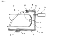
- FIG. 1 is a sectional view showing an in-vehicle lamp according to Embodiment 1 of the present invention.
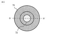
- FIG. 2 is a plan view of the moisture release side of the dehumidifying element in the in-vehicle lamp according to Embodiment 1 of the present invention.
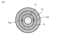
- FIG. 3 is a plan view of the dehumidifying side of the dehumidifying element in the in-vehicle lamp according to Embodiment 1 of the present invention.
- 4 is a cross-sectional view taken along the line IV-IV of FIG.
- FIG. 5 is a sectional view showing a dehumidifying element in the in-vehicle lamp according to Embodiment 1 of the present invention.
- the in-vehicle lamp 1 is, for example, a headlamp, and an optical axis extending in the vehicle front-rear direction in a lamp chamber 23 formed by a front lens (hereinafter referred to as front lens) 2 that is a translucent cover and a case 3.
- a light source 4 composed of LEDs and a reflecting mirror 5 that reflects light from the light sources 4 composed of LEDs toward the front lens 2 are accommodated.
- a mounting hole 6 is formed on the bottom surface of the case 3, a dehumidifying element 7 is fixed to the mounting hole 6, and an electrical signal from the dehumidifying element 7 is formed in a wiring through hole 9 formed on the back surface of the case 3. Is transmitted to the external control circuit 24 through the electric wire 10 passing through the.
- a resistance dew condensation detection sensor hereinafter referred to as a dew condensation detection sensor 8 which is a humidity detection element is mounted on the inner surface of the front lens 2 inside the lamp chamber 23, and an electric signal from an external control circuit 24 is received. This is transmitted through the electric wire 10 passing through the wiring through hole 9.
- FIG. 2 to FIG. 4 show an example of the configuration of the dehumidifying element 7.
- the dehumidifying element 7 is manufactured using a dehumidifying film 71 punched out into a circular shape of ⁇ 8.2 mm using a molding die. Below, the manufacturing method of this dehumidification element 7 is demonstrated.
- the dehumidifying element 7 has a structure in which a housing 73, an anode side power feeding body 74, a dehumidifying film 71, a cathode side power feeding body 75, a packing 76, and a flange 72 are laminated and integrated.
- the dehumidifying film 71 is disposed so that the surface on which the anode exists is in contact with the anode-side power feeder 74 and the surface on which the cathode is present is in contact with the cathode-side power feeder 75.
- the flange 72 and the housing 73 are formed of a graft copolymer (technopolymeric AES resin) obtained by graft copolymerizing styrene and acrylonitrile with an ethylene propylene copolymer. A material obtained by injection molding of this material is used.
- the housing 73 is provided with a male screw to be screwed into a screw hole provided in a wall surface of a device that needs to be dehumidified.
- the anode-side power feeder 74 includes a circular ring-shaped power feed portion 74B having an opening of ⁇ 6 mm, and an elongated plate-shaped power feed foot portion 74A extending from the power feed portion 74B.
- a through hole is formed at the end of the power feed foot portion. Is provided.
- the cathode-side power supply body 75 has the same shape, and the cathode-side power supply body 75 includes a circular ring-shaped power supply portion 75B having an opening of ⁇ 6 mm and an elongated plate-shaped power supply foot portion 75A extending from the power supply portion 75B. And a through hole is provided at the end of the power feed leg.
- the anode-side power feeding body 74 is a surface where a dehumidification reaction occurs and requires particularly strong corrosion resistance. Therefore, a material obtained by applying a Pt plating film on a titanium material is used.
- a stainless steel material SUS304
- the packing has a ring shape with a thickness of 500 ⁇ m with an opening of ⁇ 6 mm, and a material obtained by punching a silicon sheet with a molding die is used.
- the housing 73, the anode side power feeding body 74, the dehumidifying film 71, the cathode side power feeding body 75, the packing 76, and the flange 72 are laminated.
- the power feeding legs 74A and 75B of the anode side power feeding body 74 and the cathode side power feeding body 75 are penetrated to enable contact with the external power source 71a.
- the contact portion 77 between the flange 72 and the housing 73 is joined and integrated by ultrasonic joining.
- the output of ultrasonic bonding is 40 kHz, and the applied pressure is 5 kgf / cm 2 and held for 0.2 seconds.
- the dehumidifying element 7 manufactured by the above method is installed so that a part of the sealed dehumidified space becomes a surface on which the anode of the dehumidifying element 7 exists, and the power supply foot and the external power source 71a are connected to energize. By doing so, dehumidification in the dehumidified space is possible.
- FIG. 5 is a sectional view showing a dehumidifying element in the in-vehicle lamp according to Embodiment 1 of the present invention.
- the dehumidifying element 7 utilizing the electrolysis reaction of water is widely used in a structure in which a solid polymer electrolyte membrane, an electrode, and a catalyst layer are laminated, and a voltage is applied to the electrode via an external power source. It functions as a dehumidifying element.
- a cross section of a general dehumidifying element has a structure as shown in FIG.
- a portion excluding the external power source 71a and the conducting wire 71b is collectively referred to as a dehumidifying film 71.
- the reaction of the formula (1) that occurs in the anode catalyst layer 71e in the vicinity of the anode 71c is accompanied by generation of O 2. Therefore, the anode 71c is required to have high corrosion resistance against oxygen, and is generally plated with a noble metal film 71g. Yes. Further, H + generated by the reaction of the formula (1) reaches the cathode catalyst layer 71f via the solid polymer electrolyte membrane 71h and is used for the reaction of the formula (2).
- FIG. 6 shows a schematic diagram of the movement path of e ⁇ , H + and O 2 generated by the electrolysis reaction.
- FIG. 6 is a cross-sectional view showing the movement path of hydrogen ions and electrons in the dehumidification reaction of the in-vehicle lamp according to Embodiment 1 of the present invention.
- the e ⁇ moves from the position [A] where the electrolysis reaction of water occurs to the position [B] of the anode 71c via the anode catalyst layer 71e.
- the position [B] and the position [C] are electrically connected, and the e ⁇ moves to the position [C] having a contact point with the conducting wire 71b. After that, it moves to the position [E] of the cathode 71d via the lead wire 71b and the position [D] of the external power source 71a.
- This e ⁇ is used for the water generation reaction shown in the formula (2) at the position [F].
- H + is generated by electrolysis of water, passes through the anode catalyst layer 71e, passes through the position [G] in the solid polymer electrolyte membrane 71h, and reacts with the reaction shown in the formula (2) at the position [F].
- O 2 is released into the atmosphere after it is generated by water electrolysis. In the water generation reaction at the position [F], O 2 is supplied from the atmosphere.
- FIG. 7 and 8 show an example of the configuration of the dew condensation detection sensor.
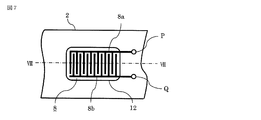
- FIG. 7 is a plan view of the dew condensation detection sensor in the in-vehicle lamp according to Embodiment 1 of the present invention as viewed from the inside.
- 8 is a cross-sectional view taken along the line VIII-VIII of FIG. 7 of the dew condensation detection sensor in the in-vehicle lamp according to Embodiment 1 of the present invention.
- the dew condensation detection sensor 8 detects a change in resistance between two opposing electrodes as an electrical signal.
- the electrode P8a and the electrode Q8b are disposed on the moisture sensitive film 12 as shown in FIG.
- the material of the electrode may be, for example, copper, copper alloy, aluminum, aluminum alloy, stainless steel metal, or a conductive material obtained by plating these metals with nickel, tin, etc., and foil-like material is preferable. .
- the electrode may be formed by any material that does not easily peel off, such as etching, screen printing, and pattern adhesion.
- the moisture sensitive film 12 is made of polyester, polyethylene, polypropylene, polystyrene, polycarbonate, polymethyl methacrylate, polyvinyl chloride, polyimide, polyurethane, paper phenol, or other synthetic resin, glass epoxy, or other inorganic material such as mica.
- a heat-resistant one is selected in consideration of the outdoor temperature in summer and the radiant heat from the light source, but one having a low thermal conductivity is desirable.
- the thickness of the moisture sensitive film 12 is made as thin as possible so that the temperature of the front lens 2 can be reliably transmitted.
- the dew condensation detection sensor 8 is formed by the photoetching method.
- the procedure is schematically shown in FIG.
- FIG. 9 is a pattern diagram showing a method for forming electrodes in the in-vehicle lamp according to Embodiment 1 of the present invention.
- the electrode shape is drawn by CAD, and a highly accurate pattern 104 is produced by the output of a laser plotter.
- the outer shape of the electrode was 10 mm ⁇ 20 mm.
- FIG. 9B when the resist 103 (photoresist) is applied to the surface of the metal thin plate 101, the surface of the metal thin plate 101 is stained to improve the adhesion of the resist 103 to the surface of the metal thin plate 101.
- a degreasing cleaning process for removing adhesion of oils and fats is performed using a cleaning liquid 102 such as hydrocarbon, acid, alkali, and microbubbles.
- the thin metal plate 101 was a C1020 copper plate having an outer shape of 20 mm ⁇ 30 mm and a thickness of 30 ⁇ m. Subsequently, as shown in FIG. 9C, a resist 103 is applied on both surfaces of the thin metal plate 101.
- a pattern 104 is attached to both sides of the resist 103.
- the pattern 104 may be suppressed by glass or the like that transmits ultraviolet rays from above while being placed on the resist 103 coating surface.
- the resist 103 is exposed 106 according to a pattern 104 using an ultraviolet light source 105.
- the blank portion (the portion that transmits ultraviolet light) of the pattern 104 is a portion where the resist 103 is baked, and as shown in FIG. 9F, the portion where the resist 103 is not baked by performing the next development processing 107 is performed.
- the resist 103 is removed.
- etching 108 is performed on the metal thin plate 101 where the resist 103 is not baked using an etching solution, here, ferric chloride.
- an etching solution here, ferric chloride.
- the electrode P8a and the electrode Q8b are affixed to the moisture sensitive film 12 at equal intervals so as not to contact each other on the moisture sensitive film 12, but the moisture sensitive film 12 has a thickness of 0.3 mm.
- Alumina was used, and an epoxy adhesive was used as the adhesive.
- the moisture sensitive film 12 may be a polymer moisture sensitive film.
- the dew condensation detection sensor 8 and the moisture sensitive film 12 combined in this way are fixed to the inner side of the front lens 2 using an adhesive, and the position to be fixed is from a light source 4 composed of LEDs as shown in FIG.
- the emitted light must be in a position that does not block the optical path that is collected by the reflecting mirror 5 and is emitted in the optical axis direction, and that is susceptible to changes in the outside air temperature.
- the front lens 2 is fixed to the inner surface of the upper surface.
- the electrical signals of the dehumidifying element 7 and the dew condensation detection sensor 8 are respectively connected to the external control circuit 24 through the wiring through hole 9 via the electric wire 10.
- the dehumidifying function for suppressing the fogging of the front lens 2 will be described. Condensation occurs when water vapor contained in the air in the vehicle lamp touches a temperature lower than the saturation temperature (dew point temperature). When the outside air temperature decreases, the front lens 2 that faces most outside is preferentially cooled in the in-vehicle lamp. Therefore, in order to grasp this condensation in advance, the condensation detection sensor 8 is arranged on the inner surface of the front lens 2.
- the control circuit 24 detects this resistance value change.
- the control circuit 24 detects this voltage change, that is, dew condensation on the front lens 2, it applies a DC voltage of 3 V to the dehumidifying element 7 and starts dehumidification in the vehicle lamp.
- the control circuit 24 operates to start dehumidification, so that it is possible to suppress the occurrence of dew condensation in the in-vehicle lamp.
- the humidity sensor is provided and the drive of the dehumidifier is controlled by the humidity change in the in-vehicle lamp.
- the humidity sensor may react to drive the dehumidifier.
- the dehumidifying element 7 since the dehumidifying element 7 is driven only when the front lens 2 is condensed regardless of the external environment, the efficiency is high.
- 10 and 11 show another configuration of the dew condensation detection sensor according to Embodiment 1 of the present invention.
- 10 is a plan view seen from the inside showing another configuration of the dew condensation detection sensor in the in-vehicle lamp according to Embodiment 1 of the present invention.
- FIG. 11 is a cross-sectional view taken along the line XI-XI of FIG. 10 of the dew condensation detection sensor in the in-vehicle lamp according to Embodiment 1 of the present invention.
- the formed electrodes P8a and Q8b can be directly attached to the front lens 2.
- a double-sided adhesive type sheet is not desirable in order to prevent a change in resistance value between electrodes due to adhesion of dust, and it is desirable to use an epoxy adhesive or the like.
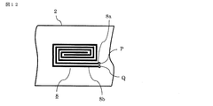
- FIG. 12 shows another pattern of the electrode P8a and the electrode Q8b.
- FIG. 12 is a plan view seen from the inside showing another electrode pattern of the dew condensation detection sensor in the in-vehicle lamp according to Embodiment 1 of the present invention.
- the electrodes shown in FIGS. 7 and 10 are comb-like, they can take any form such as a spiral as shown in FIG. 12, but it is desirable that the gap between the electrodes be made constant.
- FIG. 13 is an example of a circuit that converts a resistance change between the electrodes due to the condensation of the condensation detection sensor 8 into a voltage.
- FIG. 13 is a circuit diagram showing a circuit for converting the signal of the dew condensation detection sensor in the in-vehicle lamp according to Embodiment 1 of the present invention into a voltage change.
- V may be a 12V voltage supplied from a battery or another voltage converted by a DC-DC converter as required.
- Rp is a pull-up resistor, for example, having a value of 1 M ⁇ , and when the dew condensation detection sensor 8 is dry and the interelectrode resistance Rs is high, the voltage at the P portion shows a V value. When the resistance Rs decreases, the voltage at the P portion indicates (Rs / (Rs + Rp)) ⁇ V.
- the capacitance between the electrodes also changes due to the dew condensation of the dew condensation detection sensor 8. Therefore, the humidity detection element can be controlled by detecting the capacitance as a capacitance sensing element. Is possible.
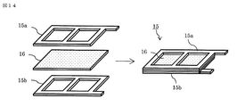
- FIG. 14 is a perspective view showing another configuration of the dew condensation detection sensor in the in-vehicle lamp according to Embodiment 1 of the present invention.
- the polymer film 16 is sandwiched between the electrode P15a and the electrode Q15b which are the dew condensation detection sensor 15, and a change in dielectric constant due to moisture absorption of the polymer film 16 is detected as a capacitance.
- the control circuit 24 detects the changed capacitance and drives the dehumidifying element 7.
- the resistance value may be detected by replacing the polymer film 16 with a hygroscopic resistance sensing sheet in the form of FIG. A combination of a resistance sensing sensor and a capacitance sensor may be used.
- FIG. 15 is a cross-sectional view showing another configuration of the in-vehicle lamp according to Embodiment 1 of the present invention.
- the dehumidifying element 7 is installed on the back surface of the case 3 in the in-vehicle lamp.
- the dehumidifying element 7 can be arranged on the back surface of the case 3.
- FIG. 16 is a sectional view showing an in-vehicle lamp according to Embodiment 2 of the present invention.
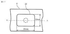
- FIG. 17 is the top view seen from the outer side which shows the dew condensation detection sensor in the vehicle-mounted lamp which concerns on Embodiment 2 of this invention.
- FIG. 18 is a cross-sectional view taken along the line SS of FIG. 17 showing the dew condensation detection sensor in the in-vehicle lamp according to Embodiment 2 of the present invention.
- FIG. 16 is a sectional view showing an in-vehicle lamp according to Embodiment 2 of the present invention.
- FIG. 17 is the top view seen from the outer side which shows the dew condensation detection sensor in the vehicle-mounted lamp which concerns on Embodiment 2 of this invention.
- FIG. 18 is a cross-sectional view taken along the line SS of FIG. 17 showing the dew condensation detection sensor in the in-vehicle lamp according to Embodiment 2 of the present invention.
- FIG. 19 is a plan view seen from the inside showing a dew condensation detection sensor in the vehicle lamp according to Embodiment 2 of the present invention.
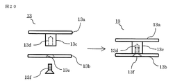
- FIG. 20 is a front view showing a heat conducting element in an in-vehicle lamp according to Embodiment 2 of the present invention.
- the basic configuration is the same as that of the first embodiment described above, but the heat conducting element 13 is provided so as to penetrate the front lens 2.
- the heat conduction element 13 is directly connected to the dew condensation detection sensor 8, and the detailed structure will be described with reference to FIGS.
- the heat conduction element 13 is composed of two parts, a heat conduction element 13a and a heat conduction element 13b.
- the heat conduction element 13a is provided with a boss 13c protruding toward the heat conduction element 13b.
- a female screw 13d is formed, and a counter seat 13e, for example, is provided through the heat conduction element 13b at a portion facing the female screw 13d.
- a countersunk screw 13f is screwed to the female screw 13d through the counter seat 13e.
- the connection is fixed by.
- the boss 13c of the heat conducting element 13a can be passed through the through hole 2A formed in the front lens 2 and fixed as shown in FIG.
- the heat conducting element 13 is fixed via a resin packing 14 in order to prevent moisture from the outside from entering the vehicle lamp.
- the dew condensation detection sensor 8 is fixed in the form of sandwiching the moisture sensitive film 12 on the inner surface of the in-vehicle lamp of the heat conducting element 13. Since the heat conduction element 13 is required to have a function to quickly transmit the outside air temperature to the in-vehicle lamp, it is desirable to use copper, copper alloy, aluminum or aluminum alloy, and to perform plating treatment in order to improve corrosion resistance. Is desirable.
- the material is C1020, the surface of which is plated with nickel, and the planar part size is 12 ⁇ 22 mm, the heat conductive element 13, the moisture sensitive film 12 using porous alumina, and the dew condensation detection sensor 8 are respectively epoxy. Fixed with a system adhesive.
- the control circuit 24 and the control algorithm are the same as those in the first embodiment.
- the heat conductive element 13 having high heat conductivity, it becomes possible to transmit the temperature drop of the outside air to the dew condensation detection sensor 8 earlier than the front lens 2. Since the dehumidifying element 7 can be driven at an earlier timing than the start of dew condensation, fogging of the front lens 2 can be suppressed with high accuracy.
- FIG. Embodiment 3 of the present invention will be described with reference to FIG. 21.
- FIG. 21 is a sectional view showing an in-vehicle lamp according to Embodiment 3 of the present invention.
- two dew condensation detection sensors 8 are provided and arranged on the upper and lower portions of the front lens 2.
- the rest is the same as in the first embodiment described above.
- the dew condensation is detected at the two positions of the front lens 2, so that the dew condensation can be detected with higher accuracy.
- a combination with the configuration of the second embodiment of the present invention may be used.
- the present invention is suitable for realizing an in-vehicle lamp capable of efficiently suppressing fogging due to condensation on the front lens of the in-vehicle lamp.
Landscapes
- Engineering & Computer Science (AREA)
- General Engineering & Computer Science (AREA)
- Physics & Mathematics (AREA)
- Microelectronics & Electronic Packaging (AREA)
- Optics & Photonics (AREA)
- Mechanical Engineering (AREA)
- Non-Portable Lighting Devices Or Systems Thereof (AREA)
- Arrangement Of Elements, Cooling, Sealing, Or The Like Of Lighting Devices (AREA)
Abstract
La présente invention concerne un phare de véhicule capable de supprimer efficacement la formation de buée sur un couvercle translucide en raison de la condensation. Le phare de véhicule comprend une chambre de phare constituée d'un couvercle translucide et d'un boîtier, un élément de déshumidification monté sur le boîtier, et un élément de détection d'humidité monté sur le côté intérieur de la chambre de phare du couvercle translucide. Dans le phare de véhicule, l'élément de déshumidification monté sur le boîtier est commandé sur la base de la détection au niveau de l'élément de détection d'humidité monté sur le côté intérieur de la chambre de lampe du couvercle translucide, de façon à supprimer efficacement la formation de buée sur le couvercle translucide due à la condensation.
Priority Applications (4)
| Application Number | Priority Date | Filing Date | Title |
|---|---|---|---|
| JP2018518176A JP6580257B2 (ja) | 2016-05-16 | 2017-04-24 | 車載用灯具 |
| CN201780023911.8A CN109154428A (zh) | 2016-05-16 | 2017-04-24 | 车载用灯具 |
| US16/093,403 US20190120456A1 (en) | 2016-05-16 | 2017-04-24 | Vehicle-mounted lamp fitting |
| EP17799122.1A EP3460315A4 (fr) | 2016-05-16 | 2017-04-24 | Phare de véhicule |
Applications Claiming Priority (2)
| Application Number | Priority Date | Filing Date | Title |
|---|---|---|---|
| JP2016-097562 | 2016-05-16 | ||
| JP2016097562 | 2016-05-16 |
Publications (1)
| Publication Number | Publication Date |
|---|---|
| WO2017199692A1 true WO2017199692A1 (fr) | 2017-11-23 |
Family
ID=60325749
Family Applications (1)
| Application Number | Title | Priority Date | Filing Date |
|---|---|---|---|
| PCT/JP2017/016146 Ceased WO2017199692A1 (fr) | 2016-05-16 | 2017-04-24 | Phare de véhicule |
Country Status (5)
| Country | Link |
|---|---|
| US (1) | US20190120456A1 (fr) |
| EP (1) | EP3460315A4 (fr) |
| JP (1) | JP6580257B2 (fr) |
| CN (1) | CN109154428A (fr) |
| WO (1) | WO2017199692A1 (fr) |
Cited By (1)
| Publication number | Priority date | Publication date | Assignee | Title |
|---|---|---|---|---|
| JP2023543913A (ja) * | 2020-10-05 | 2023-10-18 | シグニファイ ホールディング ビー ヴィ | 照明器具への水浸入を決定するための照明器具システム及び方法 |
Families Citing this family (9)
| Publication number | Priority date | Publication date | Assignee | Title |
|---|---|---|---|---|
| US10046692B2 (en) * | 2014-08-14 | 2018-08-14 | George A. Van Straten | Heated light enclosure having an adaptable heating system |
| EP3403934B1 (fr) * | 2017-05-19 | 2021-01-27 | Goodrich Lighting Systems GmbH | Soupape de vidange, unité d'éclairage d'aéronef extérieure et boîtier d'alimentation |
| ES2887007T3 (es) * | 2018-09-21 | 2021-12-21 | Goodrich Lighting Systems Gmbh | Luz exterior de aeronave y aeronave que comprende la misma |
| TWI849186B (zh) | 2019-07-17 | 2024-07-21 | 新加坡商Ams傳感器亞洲私人有限公司 | 包括增強的安全特徵的發光模組 |
| CN113532032B (zh) * | 2020-04-14 | 2023-05-12 | 上海禾赛科技有限公司 | 用于温循测试的除湿装置、包括其的温循测试装置及除湿方法 |
| US12212119B2 (en) * | 2020-04-23 | 2025-01-28 | Analog Devices International Unlimited Company | Laser system |
| FR3111656B1 (fr) * | 2020-06-23 | 2022-06-17 | Vitesco Technologies | Dispositif d’ouverture/fermeture d’ouvrant par détection de mouvement d’un membre d’utilisateur et procédé d’ouverture/fermeture associé |
| DE102020005140B4 (de) | 2020-08-21 | 2023-02-09 | Mercedes-Benz Group AG | Scheinwerfer für ein Fahrzeug |
| JP7468415B2 (ja) * | 2021-03-16 | 2024-04-16 | 三菱電機株式会社 | 半導体装置、電力変換装置、及び半導体装置の製造方法 |
Citations (4)
| Publication number | Priority date | Publication date | Assignee | Title |
|---|---|---|---|---|
| JP2013157241A (ja) * | 2012-01-31 | 2013-08-15 | Sharp Corp | 照明装置 |
| WO2013175538A1 (fr) * | 2012-05-24 | 2013-11-28 | 三菱電機株式会社 | Dispositif d'élimination d'humidité, dispositif d'éclairage pour montage sur véhicule, dispositif d'éclairage à source de lumière |
| JP2014161760A (ja) * | 2013-02-22 | 2014-09-08 | Mitsubishi Electric Corp | 機器用除湿装置及び車載用ヘッドランプ |
| JP2014167445A (ja) * | 2013-02-28 | 2014-09-11 | Sharp Corp | 湿度センサおよび湿度センサの製造方法 |
Family Cites Families (18)
| Publication number | Priority date | Publication date | Assignee | Title |
|---|---|---|---|---|
| JPS63161334A (ja) * | 1986-12-24 | 1988-07-05 | Toshiba Corp | 換気扇の運転装置 |
| KR100486497B1 (ko) * | 2002-08-13 | 2005-04-29 | 엘지전자 주식회사 | 히터 내장형 감습센서 및 그 제조방법 |
| DE10359748A1 (de) * | 2003-12-19 | 2005-07-28 | Dr.Ing.H.C. F. Porsche Ag | Lichttechnische Einrichtung |
| CN100581858C (zh) * | 2004-09-15 | 2010-01-20 | 麦格纳唐纳利工程有限公司 | 一种车辆环境控制系统 |
| US7504957B2 (en) * | 2006-01-10 | 2009-03-17 | Guardian Industries Corp. | Light sensor embedded on printed circuit board |
| WO2009044942A1 (fr) * | 2007-10-01 | 2009-04-09 | Auto Electronic Corporation. | Appareil pour détecter une vitre embuée de véhicule |
| KR101072715B1 (ko) * | 2009-10-05 | 2011-10-11 | 인하대학교 산학협력단 | 램프용 습기제거장치 |
| KR20120050268A (ko) * | 2010-11-10 | 2012-05-18 | 현대자동차주식회사 | 차량용 헤드램프의 제습 방법 |
| JP2013089353A (ja) * | 2011-10-14 | 2013-05-13 | Koito Mfg Co Ltd | 車両用灯具 |
| US20130208496A1 (en) * | 2012-01-31 | 2013-08-15 | Sharp Kabushiki Kaisha | Illuminating device |
| KR101613075B1 (ko) * | 2012-03-21 | 2016-04-19 | 현대모비스 주식회사 | 차량용 램프 장치 |
| DE102013218327A1 (de) * | 2013-09-12 | 2015-03-12 | Automotive Lighting Reutlingen Gmbh | Kfz-Beleuchtungseinrichtung |
| KR20160014452A (ko) * | 2014-07-29 | 2016-02-11 | 현대모비스 주식회사 | 차량용 헤드램프 |
| JP6803130B2 (ja) * | 2014-11-19 | 2020-12-23 | 日東電工株式会社 | ランプ |
| KR101626774B1 (ko) * | 2015-05-21 | 2016-06-02 | 박용국 | 차량 램프 제습장치 |
| KR20160139777A (ko) * | 2015-05-28 | 2016-12-07 | 엘지이노텍 주식회사 | 차량용 램프 |
| US9982857B2 (en) * | 2015-10-20 | 2018-05-29 | Toyota Motor Engineering & Manufacturing North America, Inc. | Vehicle lights including moisture management apparatuses |
| JP6823371B2 (ja) * | 2015-12-17 | 2021-02-03 | 日東電工株式会社 | 通気調湿ユニットおよび機器 |
-
2017
- 2017-04-24 WO PCT/JP2017/016146 patent/WO2017199692A1/fr not_active Ceased
- 2017-04-24 CN CN201780023911.8A patent/CN109154428A/zh active Pending
- 2017-04-24 EP EP17799122.1A patent/EP3460315A4/fr not_active Withdrawn
- 2017-04-24 US US16/093,403 patent/US20190120456A1/en not_active Abandoned
- 2017-04-24 JP JP2018518176A patent/JP6580257B2/ja active Active
Patent Citations (4)
| Publication number | Priority date | Publication date | Assignee | Title |
|---|---|---|---|---|
| JP2013157241A (ja) * | 2012-01-31 | 2013-08-15 | Sharp Corp | 照明装置 |
| WO2013175538A1 (fr) * | 2012-05-24 | 2013-11-28 | 三菱電機株式会社 | Dispositif d'élimination d'humidité, dispositif d'éclairage pour montage sur véhicule, dispositif d'éclairage à source de lumière |
| JP2014161760A (ja) * | 2013-02-22 | 2014-09-08 | Mitsubishi Electric Corp | 機器用除湿装置及び車載用ヘッドランプ |
| JP2014167445A (ja) * | 2013-02-28 | 2014-09-11 | Sharp Corp | 湿度センサおよび湿度センサの製造方法 |
Non-Patent Citations (1)
| Title |
|---|
| See also references of EP3460315A4 * |
Cited By (1)
| Publication number | Priority date | Publication date | Assignee | Title |
|---|---|---|---|---|
| JP2023543913A (ja) * | 2020-10-05 | 2023-10-18 | シグニファイ ホールディング ビー ヴィ | 照明器具への水浸入を決定するための照明器具システム及び方法 |
Also Published As
| Publication number | Publication date |
|---|---|
| JP6580257B2 (ja) | 2019-09-25 |
| CN109154428A (zh) | 2019-01-04 |
| EP3460315A4 (fr) | 2019-10-23 |
| EP3460315A1 (fr) | 2019-03-27 |
| JPWO2017199692A1 (ja) | 2018-08-09 |
| US20190120456A1 (en) | 2019-04-25 |
Similar Documents
| Publication | Publication Date | Title |
|---|---|---|
| JP6580257B2 (ja) | 車載用灯具 | |
| EP3222339B1 (fr) | Lampe avec dispositif de déshumidification | |
| JP5705377B2 (ja) | 除湿装置、車載用灯具および光源点灯装置 | |
| US7868339B2 (en) | Illuminating device | |
| JP2007230450A (ja) | 車室内用照明装置 | |
| JP2006196395A (ja) | タッチスイッチ | |
| JP2012201115A (ja) | ランプユニット | |
| JP6204206B2 (ja) | 自立型調光システム | |
| CN211281292U (zh) | 一种脚踏呼吸灯 | |
| JP2015118890A (ja) | 静電容量式操作装置 | |
| JP5482568B2 (ja) | 有機elモジュールおよび有機el照明装置 | |
| CN113883474A (zh) | 一种车辆超薄尾灯 | |
| CN223259025U (zh) | 液体位置传感器 | |
| JP2019059382A (ja) | 乗物用照明装置 | |
| JP5263594B2 (ja) | 照明装置 | |
| JP2015126180A (ja) | 融雪太陽電池パネルおよび融雪パネル | |
| JP7672099B2 (ja) | 導体付き積層体、面状ヒータ、光学センサ及び導体付き樹脂材 | |
| KR102771287B1 (ko) | 센서 어레이 및 이를 포함하는 가스 센싱 장치 | |
| JP2004241206A (ja) | 燃料電池車における水素ガス検知装置 | |
| JP2010267606A (ja) | 車両用スイッチ | |
| US9994446B1 (en) | Moisture electrolysis apparatus for headlamp | |
| JP2005146566A (ja) | 両面発光視線誘導標識 | |
| JP2008159307A (ja) | メンブレンスイッチ |
Legal Events
| Date | Code | Title | Description |
|---|---|---|---|
| ENP | Entry into the national phase |
Ref document number: 2018518176 Country of ref document: JP Kind code of ref document: A |
|
| NENP | Non-entry into the national phase |
Ref country code: DE |
|
| 121 | Ep: the epo has been informed by wipo that ep was designated in this application |
Ref document number: 17799122 Country of ref document: EP Kind code of ref document: A1 |
|
| ENP | Entry into the national phase |
Ref document number: 2017799122 Country of ref document: EP Effective date: 20181217 |