WO2017199736A1 - Unité de barre omnibus et machine dynamo-électrique - Google Patents
Unité de barre omnibus et machine dynamo-électrique Download PDFInfo
- Publication number
- WO2017199736A1 WO2017199736A1 PCT/JP2017/016985 JP2017016985W WO2017199736A1 WO 2017199736 A1 WO2017199736 A1 WO 2017199736A1 JP 2017016985 W JP2017016985 W JP 2017016985W WO 2017199736 A1 WO2017199736 A1 WO 2017199736A1
- Authority
- WO
- WIPO (PCT)
- Prior art keywords
- bus bar
- phase
- main body
- insulating block
- terminal
- Prior art date
- Legal status (The legal status is an assumption and is not a legal conclusion. Google has not performed a legal analysis and makes no representation as to the accuracy of the status listed.)
- Ceased
Links
Images




Classifications
-
- H—ELECTRICITY
- H02—GENERATION; CONVERSION OR DISTRIBUTION OF ELECTRIC POWER
- H02K—DYNAMO-ELECTRIC MACHINES
- H02K3/00—Details of windings
- H02K3/46—Fastening of windings on the stator or rotor structure
- H02K3/52—Fastening salient pole windings or connections thereto
- H02K3/521—Fastening salient pole windings or connections thereto applicable to stators only
- H02K3/522—Fastening salient pole windings or connections thereto applicable to stators only for generally annular cores with salient poles
-
- H—ELECTRICITY
- H02—GENERATION; CONVERSION OR DISTRIBUTION OF ELECTRIC POWER
- H02K—DYNAMO-ELECTRIC MACHINES
- H02K3/00—Details of windings
- H02K3/46—Fastening of windings on the stator or rotor structure
- H02K3/50—Fastening of winding heads, equalising connectors, or connections thereto
-
- H—ELECTRICITY
- H02—GENERATION; CONVERSION OR DISTRIBUTION OF ELECTRIC POWER
- H02K—DYNAMO-ELECTRIC MACHINES
- H02K3/00—Details of windings
- H02K3/32—Windings characterised by the shape, form or construction of the insulation
- H02K3/38—Windings characterised by the shape, form or construction of the insulation around winding heads, equalising connectors, or connections thereto
-
- H—ELECTRICITY
- H02—GENERATION; CONVERSION OR DISTRIBUTION OF ELECTRIC POWER
- H02K—DYNAMO-ELECTRIC MACHINES
- H02K2203/00—Specific aspects not provided for in the other groups of this subclass relating to the windings
- H02K2203/09—Machines characterised by wiring elements other than wires, e.g. bus rings, for connecting the winding terminations
Definitions
- the present invention relates to a power distribution bus bar unit connected to a stator coil and a rotating electrical machine including the same.
- an annular bus bar unit that distributes current from a power supply terminal to each winding is known.
- Patent Document 1 there are three arc-shaped bus bars that are arranged so as to be shifted from each other in the circumferential direction and electrically connect coils corresponding to each phase, and an arc-shaped bus bar that electrically connects neutral points of each coil.
- a bus bar unit including a neutral point bus bar and a bus bar base having a triple annular groove for accommodating all the bus bars is disclosed.
- Patent Document 2 discloses that arc-shaped bus bars for U-phase, V-phase, W-phase, and neutral point are vertically arranged inside an insulating member for the purpose of miniaturization while ensuring insulation between the bus bars.
- a bus bar module is disclosed in which two are arranged in two stages.
- an object of the present invention is to provide a bus bar unit that can easily cope with an increase in the number of sets of coils of each phase while reducing the overall size, and a rotating electrical machine including the bus bar unit. Is to provide.
- a bus bar unit includes an annular insulating block, a first bus bar, a second bus bar, a third bus bar, and a fourth bus bar.
- the insulating block is made of an electrically insulating material and has an axis parallel to the first axis.
- the first bus bar includes an arc-shaped first main body disposed inside the insulating block, and a plurality of terminal portions configured to be connectable to the first coil end and projecting radially from the insulating block. And a first connection terminal.
- the second bus bar includes an arc-shaped second main body disposed inside the insulating block and a plurality of terminal portions configured to be connectable to the second coil end and projecting radially from the insulating block. And a second connection terminal.
- the second main body is disposed at a distance from the first main body in the first axial direction.
- the third bus bar includes an arc-shaped third main body disposed inside the insulating block and a plurality of terminal portions configured to be connectable to a third coil end and projecting radially from the insulating block.
- a third connection terminal is disposed at a radial distance from the first main body portion, and the third connection terminal is provided between the first main body portion and the second main body portion.
- the fourth bus bar includes an arcuate fourth main body portion disposed inside the insulating block, and a plurality of terminal portions configured to be connectable to the fourth coil end and projecting radially from the insulating block. And a fourth connection terminal.
- the fourth main body is disposed at a distance from the third main body in the first axial direction, and the fourth connection terminal is the first main body and the second main body. At least one terminal portion passing between the first and second terminals.
- connection terminals (third and fourth connection terminals) of the third and fourth bus bars are between the main body portions (first and second main body portions) of the first and second bus bars. Since at least one terminal part which passes is included, respectively, the freedom degree of the arrangement position of the 3rd and 4th connecting terminal increases. Accordingly, it is possible to easily cope with an increase in the number of sets of coils of each phase while reducing the size of the entire bus bar unit.
- the insulating block includes a first main surface that covers the first and third main body portions, a second main surface that covers the second and fourth main body portions, and the first and second main surfaces.
- the first to fourth connection terminals may be configured to project radially outward from the outer peripheral surface.
- the first to fourth bus bars include a U-phase bus bar connected to one end of the U-phase coil, a V-phase bus bar connected to one end of the V-phase coil, and a W-phase bus bar connected to one end of the W-phase coil. And a neutral point bus bar connected to the other end of each of the U-phase, V-phase, and W-phase coils, and the first and second bus bars are radially outward of the third and fourth bus bars.
- Each of the neutral bus bars may be one of the first and second bus bars. Since the neutral point bus bar has many connection terminals, the neutral point bus bar is arranged on the outer peripheral side of the diameter, so that each connection terminal can be easily arranged on the outer peripheral surface of the insulating block without requiring special processing. can do.
- Each of the U-phase, V-phase, and W-phase bus bars further has an external terminal protruding from the first main surface in the first axial direction, and each of the external terminals is in the first axial direction. May have a joint surface perpendicular to the second axial direction perpendicular to each other. This facilitates connection of power to the U-phase, V-phase, and W-phase bus bars.
- the third bus bar may further include a bent portion that converts the height position of the third connection terminal.
- the bent portion may be provided in the third main body portion or may be provided in the third connection terminal.
- the bent portion is provided in the third body portion, it is possible to reduce the size (smaller diameter) of the insulating block in the radial direction, and when the bent portion is provided in the third connection terminal, the insulating block is provided. It is possible to achieve downsizing (thinning) in the axial direction.
- the fourth bus bar may further include a bent portion that converts the height position of the fourth connection terminal.
- the bent portion may be provided in the fourth main body portion or may be provided in the fourth connection terminal.
- a rotating electrical machine includes the bus bar unit configured as described above.
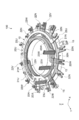
- FIG. 1 is an overall perspective view of a bus bar unit according to an embodiment of the present invention. It is a permeation
- FIG. 1 is an overall perspective view of a bus bar unit according to an embodiment of the present invention
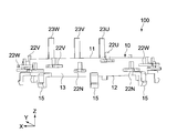
- FIG. 2 is a transparent perspective view showing its internal structure
- FIG. 3 is a transparent top view thereof
- FIG. 4 is a transparent bottom view thereof
- FIG. It is a side view.
- the X axis, the Y axis, and the Z axis indicate three axial directions that are orthogonal to each other.
- the arrow direction of the Z axis is described as the upper side.
- the bus bar unit 100 of the present embodiment includes an insulating block 10 and a plurality of bus bars (U-phase bus bar 20U, V-phase bus bar 20V, W-phase bus bar 20W, neutral point bus bar 20N) arranged inside the insulating block 10.
- bus bars U-phase bus bar 20U, V-phase bus bar 20V, W-phase bus bar 20W, neutral point bus bar 20N
- the bus bar unit 100 of the present embodiment constitutes a part of a rotating electric machine such as a three-phase AC motor or a generator, is fixed to a casing that accommodates a rotor or the like, and is wound on a stator core (U phase, V Phase and W phase) stator coils.
- a stator core U phase, V Phase and W phase
- the insulating block 10 supports a plurality of bus bars and electrically insulates the bus bars. As shown in FIG. 1, the insulating block 10 is formed of a substantially annular molded body having an axis parallel to the Z-axis direction.
- the electrically insulating material constituting the insulating block 10 is typically made of a resin material.
- the resin material is not particularly limited, and is made of engineering plastics such as PPS (polyphenylene sulfide) and PBT (polybutylene terephthalate).
- the resin material may contain fillers such as glass fibers and insulating inorganic particles for the purpose of improving strength.
- the insulating block 10 includes an upper surface 11 (first main surface), a bottom surface 12 (second main surface), an outer peripheral surface 13 connected to the outer periphery of each of the upper surface 11 and the bottom surface 12, and each of the upper surface 11 and the bottom surface 12. And an inner peripheral surface portion 14 connected to the inner peripheral edge portion.
- the upper surface 11 is provided with U-phase, V-phase, and W-phase external terminals 23U, 23V, and 23W that protrude upward in FIG. 1 along the axial center direction (Z-axis direction) of the insulating block 10.
- the outer peripheral surface 13 is provided with neutral points (N-phase), U-phase, V-phase, and W-phase connection terminals 22N, 22U, 22V, and 22W that protrude outward in the radial direction of the insulating block 10.
- a plurality of engaging protrusions 15 that can be engaged with the inner peripheral surface of the casing are provided on the bottom surface 12 side of the outer peripheral surface 13 of the insulating block 10.
- the engagement protrusions 15 are arranged at intervals in the circumferential direction of the outer peripheral surface 13, and the bus bar unit 100 is fixed to the casing via the engagement protrusions 15.
- the size of the insulating block 10 is not particularly limited, and in this example, the outer diameter is about 60 mm, the inner diameter is about 37 mm, and the thickness is about 8 mm.
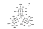
- FIG. 6 is an equivalent circuit diagram of the stator coil 30 that is electrically connected to the bus bar unit 100.
- the stator coil 30 has three sets of U-phase coils 31U to 33U, V-phase coils 31V to 33V, and W-phase coils 31W to 31W.
- the bus bar unit 100 distributes current supplied from a power source (not shown) to the U-phase coils 31U to 33U, the V-phase coils 31V to 33V, and the W-phase coils 31W to 33W via the external terminals 23U, 23V, and 23W.
- white circles represent connection terminals 22N, 22U, 22V, 22W and external terminals 23U, 23V, 23W of each bus bar connected to the coils of each phase.
- each U-phase coil 31U to 33U is connected to U-phase external terminal 23U via U-phase bus bar 20U, and the other end (coil end) is connected to neutral point connection terminal 21N.
- the U-phase coils 31U to 33U are connected in parallel between the U-phase external terminal 23U and the neutral point connection terminal 21N.
- each of the V-phase coils 31V to 33V is connected to the V-phase external terminal 23V via the V-phase bus bar 20V, and the other end (coil end) thereof is connected to the neutral point connection terminal 21N.
- the V-phase coils 31V to 33V are connected in parallel between the V-phase external terminal 23V and the neutral point connection terminal 21N.
- each W-phase coil 31W to 33W is connected to the W-phase external terminal 23W via the W-phase bus bar 20W, and the other end (coil end) is connected to the neutral point connection terminal 21N. Is done.
- Each of the W-phase coils 31W to 33W is connected in parallel between the W-phase external terminal 23W and the neutral point connection terminal 21N.
- the plurality of bus bars include a U-phase bus bar 20U, a V-phase bus bar 20V, a W-phase bus bar 20W, and a neutral point bus bar 20N. These bus bars have arcuate body portions 21U, 21V, 21W, and 21N that are arranged in two stages, two above and below, as shown in FIG.
- main body portion 21N of the neutral point bus bar 20N is formed in an annular shape (see FIG. 4), it is formed in an arc shape like the main body portions 21U, 21V, 21W of the other bus bars 20U, 20V, 20W. Therefore, the main body portion 21N of the neutral point bus bar 20 will be described as being synonymous with the arc shape.
- the main body portions 21N, 21U, 21V, and 21W of each bus bar are disposed inside the insulating block 10, and are electrically insulated by a resin material that constitutes the insulating block 10 therebetween.
- the main body portion 21U of the U-phase bus bar 20U and the main body portion 21N of the neutral point bus bar 20N are respectively disposed above and below the outer peripheral side of the insulating block 10, and the W-phase bus bar is disposed above and below the inner peripheral side of the insulating block 10.
- a main body 21W of 20W and a main body 21V of the V-phase bus bar 20V are respectively arranged.
- the U-phase bus bar 20U (first bus bar) is arranged on the outer peripheral side of the upper surface of the four bus bars, as shown in FIGS.
- the U-phase bus bar 20U is formed of a stamped press-molded body of a metal plate (for example, copper plate) having a predetermined thickness (for example, about 1 mm), and a U-phase connection composed of a main body portion 21U (first main body portion) and a plurality of terminal portions. It has a terminal 22U (first connection terminal) and a U-phase external terminal 23U.
- the main body portion 21U has an arc shape of approximately 240 ° centering on the axis C of the insulating block 10, and U-phase connection terminals including a total of three terminal portions at both ends and intermediate portions thereof. 22U are provided at intervals of 120 °.
- the main body 21U is made of a plate material having a predetermined width parallel to the XY plane.
- the U-phase connection terminal 22U extends radially from the outer peripheral surface of the main body portion 21U in the radial direction, and these tip portions protrude from the outer peripheral surface 13 of the insulating block 10 by a predetermined length. These three U-phase connection terminals 22U are provided on substantially the same plane as the main body 21U.
- the width of the U-phase connection terminal 22U is not particularly limited, and is formed to be slightly wider than the main body portion 21U in the present embodiment.
- the U-phase external terminal 23U is provided at one end of the main body 21U, extends upward from the end via the connecting portion 24U, and protrudes from the upper surface 11 of the insulating block 10 by a predetermined length.
- the U-phase external terminal 23U is made of a plate material having a predetermined width having a main surface 230 (joint surface) perpendicular to the Y-axis direction, and is attached to a connector (not shown) connected to a power source.
- the electrical connection of the U-phase external terminal 23U to the connector employs a press-fitting connection by press-fit, but is not limited thereto, and joining by welding may be employed.
- the connecting portion 24U is for guiding the U-phase external terminal 23U to a predetermined position on the upper surface 11 of the insulating block 10, and is formed in a predetermined shape in the same plane as the main body portion 21U.
- the neutral point bus bar 20N (second bus bar) is disposed on the outer peripheral side of the lower surface of the four bus bars, as shown in FIGS.
- the neutral point bus bar 20N is formed of a stamped press-molded body of a metal plate having a predetermined thickness like the U-phase bus bar 20U, and has a neutral point connection composed of a main body portion 21N (second main body portion) and a plurality of terminal portions. Terminal 22N (second connection terminal).
- the main body portion 21N has an annular shape centered on the axis C of the insulating block 10, and a neutral point connection terminal 22N composed of a total of nine terminal portions is provided on the outer peripheral surface thereof.
- the main body portion 21N is composed of a plate material having a predetermined width parallel to the XY plane.
- Main body portion 21N is arranged at a first interval in the Z-axis direction from main body portion 21U of U-phase bus bar 20U.
- the first interval is not particularly limited as long as it can secure a predetermined withstand voltage between the main body portion 21U and the main body portion 21N, and is, for example, about 1 mm to 2 mm.
- the neutral point connection terminals 22N extend radially from the outer peripheral surface of the main body portion 21N in the radial direction, and their tip portions protrude from the outer peripheral surface 13 of the insulating block 10 by a predetermined length.
- the neutral point connection terminals 22N are provided on the outer peripheral surface of the main body portion 21N at intervals of 40 °, and are provided on substantially the same plane as the main body portion 21N.
- the width of the neutral point connection terminal 22N is not particularly limited, and is formed to be slightly wider than the main body 21N in the present embodiment.
- V-phase bus bar 20V (fourth bus bar) is disposed on the inner surface of the lower surface of the four bus bars, as shown in FIGS.
- the V-phase bus bar 20V is configured by a stamped press-molded body of a metal plate having a predetermined thickness like the U-phase bus bar 20U, and includes a main body portion 21V (fourth main body portion) and a V-phase connection terminal 22V composed of a plurality of terminal portions. (Fourth connection terminal) and a V-phase external terminal 23V.
- the main body 21V has an arc shape of approximately 240 ° centering on the axis C of the insulating block 10, and a total of three V-phase connection terminals 22V are 120 ° at both ends and an intermediate portion thereof. Provided at intervals.
- the main body portion 21V is made of a plate material having a predetermined width parallel to the XY plane, has an outer diameter smaller than the main body portion 21N of the neutral point bus bar 20N, and has a second interval in the radial direction with respect to the main body portion 21N. Placed.
- the second interval is not particularly limited as long as it can secure a predetermined withstand voltage between the main body 21N and the main body 21V, and is, for example, about 2 mm to 3 mm.
- the V-phase connection terminal 22V extends radially from the outer peripheral surface of the main body portion 21V in the radial direction, and these tip portions protrude from the outer peripheral surface 13 of the insulating block 10 by a predetermined length.
- two terminal portions located at both ends of the main body portion 21V are between the main body portion 21U of the U-phase bus bar 20 and the main body portion 21N of the neutral point bus bar 20N.
- the other one terminal portion passes through and is located in an open area of an arc that constitutes the main body portion 21U when viewed from the Z-axis direction (see FIG. 3).
- the width of the V-phase connection terminal 22V is not particularly limited, and is formed to be slightly wider than the main body portion 21V in the present embodiment.
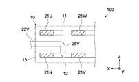
- FIG. 7 is a schematic cross-sectional view of the main part of the bus bar unit 100.
- Each V-phase connection terminal 22V has a bent portion 25V.
- the bent portion 25V is a base portion of the V-phase connection terminal 22V and is provided within the second interval (between the main body portion 21V and the main body portion 21N).
- the bent portion 25V is the height position of the V-phase connection terminal 22V from the height position of the main body portion 21V to the height position between the main body portion 21U of the U-phase bus bar 20U and the main body portion 21N of the neutral point bus bar 20N. It is formed into a crank shape that transforms into These V-phase connection terminals 22V are provided at the same height position on the outer peripheral surface 13 of the insulating block 10, respectively.
- the V-phase external terminal 23V is provided at a predetermined position on the outer peripheral surface of the main body 21V, extends upward from the predetermined position, and protrudes from the upper surface 11 of the insulating block 10 by a predetermined length.
- the V-phase external terminal 23V is made of a plate material having a predetermined width having a main surface (joint surface) 230 perpendicular to the Y-axis direction, and is attached to a connector (not shown) connected to a power source.
- V-phase external terminal 23V is arranged to face U-phase external terminal 23U in the X-axis direction.
- the electrical connection of the V-phase external terminal 23V to the connector employs a press-fitting connection by press-fit, but is not limited thereto, and joining by welding may be employed.
- W-phase bus bar And W phase bus bar 20W (3rd bus bar) is arrange
- the W-phase bus bar 20W is configured by a stamped press-molded body of a metal plate having a predetermined thickness similarly to the U-phase bus bar 20U, and includes a main body portion 21W (third main body portion) and a W-phase connection terminal 22W including a plurality of terminal portions. (Third connection terminal) and a W-phase external terminal 23W.
- the main body 21W has an arc shape of approximately 240 ° centered on the axis C of the insulating block 10, and a total of three W-phase connection terminals 22W are 120 ° at both ends and the middle thereof. Provided at intervals.
- the main body portion 21W is made of a plate material having a predetermined width parallel to the XY plane, has an outer diameter smaller than the main body portion 21U of the U-phase bus bar 20U, and has a second interval in the radial direction with respect to the main body portion 21U. Arranged. Furthermore, the main body 21W is arranged at a first interval in the Z-axis direction from the main body 21V of the V-phase bus bar 20V.
- the W-phase connection terminals 22W extend radially from the outer peripheral surface of the main body portion 21W in the radial direction, and their tips protrude from the outer peripheral surface 13 of the insulating block 10 by a predetermined length.
- two terminal portions located at one end portion of the main body portion 21W and an intermediate portion between both end portions of the main body portion 21W are connected to the main body portion 21U of the U-phase bus bar 20.
- the other one terminal portion passes between the neutral point bus bar 20N and the main body portion 21N, and is located in an open area of an arc constituting the main body portion 21U when viewed from the Z-axis direction (see FIG. 3).
- the width of the W-phase connection terminal 22W is not particularly limited, and is formed to be slightly wider than the main body 21W in the present embodiment.
- FIG. 8 is a schematic cross-sectional view of the main part of the bus bar unit 100.
- Each W-phase connection terminal 22W has a bent portion 25W.
- the bent portion 25W is a base portion of the W-phase connection terminal 22W and is provided within the second interval (between the main body portion 21W and the main body portion 21U).
- the bent portion 25W is a height position between the main body portion 21U of the U-phase bus bar 20U and the main body portion 21N of the neutral point bus bar 20N from the height position of the main body portion 21W. It is formed into a crank shape that transforms into These W-phase connection terminals 22W are provided at the same height position on the outer peripheral surface 13 of the insulating block 10 and at the same height position as the V-phase connection terminal 22V (see FIG. 5).
- the W-phase external terminal 23W is provided in the vicinity of one end of the main body 21W, extends upward from the vicinity of the end via the connecting portion 24W, and protrudes from the upper surface 11 of the insulating block 10 by a predetermined length. .
- the W-phase external terminal 23W is made of a plate material having a predetermined width having a main surface 230 (joint surface) perpendicular to the Y-axis direction, and is attached to a connector (not shown) connected to a power source.
- W-phase external terminal 23W is arranged to face V-phase external terminal 23V in the X-axis direction.
- the electrical connection of the W-phase external terminal 23W to the connector employs a press-fitting connection by press-fit, but is not limited thereto, and joining by welding may be employed.
- the connecting portion 24W is for guiding the W-phase external terminal 23W to a predetermined position on the upper surface 11 of the insulating block 10, and is formed in a predetermined shape in the same plane as the main body portion 21W.
- connection terminals 22N, 22U, 22V, and 22W of each bus bar are respectively arranged at predetermined height positions on the outer peripheral surface 13 of the insulating block 10, and each is equiangular (20 in the circumferential direction when viewed from the Z-axis direction. °) arranged at intervals (see FIGS. 3 and 4).
- the U-phase connection terminal 22U, the V-phase connection terminal 22V, and the W-phase connection terminal W are sequentially arranged with the neutral point connection terminal 22N interposed therebetween.
- operativity of the stator coil 30 with respect to each connection terminal is ensured.
- connection terminals 22N, 22U, 22V, and 22W of each bus bar are formed in the same shape.
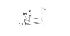
- FIG. 9 shows the form of the tip of the neutral point connection terminal 22N.
- the distal end portion of the connection terminal 22 ⁇ / b> N has a housing portion 221 formed at the center portion and a vertically rising wall portion 222 connected to the bottom portion of the housing portion 221.
- Each coil end of the stator coil 30 is fixed to the rising wall portion 222 by welding in a state of being accommodated in the accommodating portion 221.
- a tapered portion 223 is provided at the opening end of the housing portion 221, and the workability of housing the coil end from the radially outer side to the housing portion 221 is ensured.
- the bus bar unit 100 is manufactured by an insert molding method. Although details are omitted, after the bus bars 20N, 20U, 20V, and 20W are arranged in a predetermined positional relationship in the cavity of the mold, the resin material constituting the insulating block 10 is injection-molded in the cavity. At this time, the main body portion of an arbitrary bus bar may be partially deformed in consideration of the filling property of the resin into the cavity, the insertion position of the insert pin, and the like.
- the main body portion 21U of the U-phase bus bar 20U has a detour portion 21U1 that detours one end thereof to a position immediately above the main body portion 21V of the V-phase bus bar 20V as shown in FIG.
- each of the three U-phase connection terminals 21U, the V-phase connection terminal 21V, and the W-phase connection terminal 21W includes three U-phase coils 31U to 33U and V-phase coils 31V to 31V, respectively.
- One end of each of the 33V and W phase coils 31W to 33W is connected.
- the nine neutral point connection terminals 21N are connected to the other ends of the U, V, and W phase coils 31U to 33U, 31V to 33V, and 31W to 33W, respectively.
- the bus bar unit 100 distributes a current supplied from a power source (not shown) to the U-phase coils 31U to 33U, the V-phase coils 31V to 33V, and the W-phase coils 31W to 33W via the external terminals 23U, 23V, and 23W.
- the rotor is rotated at a predetermined rotation speed in a predetermined direction.
- connection terminals 22V and 22W of the V-phase and W-phase bus bars 20V and 20W include at least one terminal portion that passes between the body portions 21U and 21N of the U-phase and neutral point bus bars 20U and 20N, respectively. .
- the connection terminals of each bus bar can be protruded in the same direction even at a position where two bus bars in the same stage face each other in the radial direction.
- the arrangement positions of the V-phase and W-phase connection terminals 22V and 22W The degree of freedom is increased.
- connection terminals 22N, 22U, 22V, and 22W of each bus bar are concentrated on the outer peripheral surface 13 of the insulating block 10 in a predetermined arrangement form, each of the connection terminals 22N, 22U, 22V, and 22W.
- the neutral point bus bar 20N since the neutral point bus bar 20N has many connection terminals 22N, the neutral point bus bar 20N is arranged on the outer peripheral side of the diameter of the insulating block 10 and requires special processing of each connection terminal 22N. And can be easily arranged on the outer peripheral surface 13 of the insulating block 10.
- connection terminals 22V and 22W of the V-phase and W-phase bus bars 20V and 20W are respectively provided with bent portions 25V and 25W for converting their height positions.
- a space necessary for forming the bent portions 25V and 25W is secured in the interval between the V-phase and W-phase bus bars 20V and 20W and the interval (first interval) between the U-phase and neutral point bus bars 20U and 20N. Since it becomes unnecessary, it is possible to reduce the size (thinning) of the insulating block 10 in the axial direction.
- the external terminals 23U, 23V, 23W of each phase are arranged so as to be aligned in the X-axis direction.
- the main surfaces of the external terminals 23U, 23V, and 23W are arranged so as to be perpendicular to the Y-axis direction, connection to a connector (not shown) connected to the power source is facilitated.
- the connector is typically mounted on a circuit board disposed in the motor casing so as to face the upper surface 11 of the bus bar unit 100, and 3 corresponding to each external terminal 23 U, 23 V, 23 W.
- Each connector has an elastic metal fitting that clamps the main surfaces of these external terminals 23U, 23V, and 23W, and is attached to the individual external terminals 23U, 23V, and 23W together with the circuit board being mounted in the casing.
- the main surfaces of the external terminals 23U, 23V, and 23W are directed in the same direction, the positions where the connectors are properly attached to the individual external terminals 23U, 23V, and 23W are uniquely determined. This prevents erroneous assembly of the connector to the external terminals 23U, 23V, and 23W.
- FIG. 10 shows a second embodiment of the present invention.
- the configuration different from the first embodiment will be mainly described, and the same configuration as the first embodiment will be denoted by the same reference numeral, and the description thereof will be omitted or simplified.
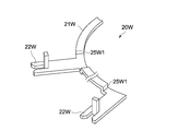
- the bent portions 25V and 25W that convert the height positions of the V-phase and W-phase connection terminals 22V and 22W into the height positions between the U-phase bus bar 20U and the neutral point bus bar 20N are the main body portions 21V, It differs from the first embodiment in that it is provided at 21W.
- a bent portion 25W1 for converting the height position of the W-phase connection terminal 22W is provided in the main body portion 21W.
- the bent portion 25W1 is formed of a concave portion, the radial region of the main body portion 21W necessary for conversion of the height position of the W-phase connection terminal 22W can be substantially eliminated.
- Such a configuration can be similarly applied to the main body 21V of the V-phase bus bar 20V.
- the interval between the body portions 21W and 21U of the W-phase bus bar 20W and the U-phase bus bar 20U and the interval between the body portions 21V and 21V of the V-phase bus bar 20V and the neutral point bus bar 20N (second ) To reduce the size (smaller diameter) of the bus bar unit 100 in the radial direction.
- the motor bus bar unit has been described as an example.
- the present invention is not limited to this, and the present invention can also be applied to other rotating electric machines, that is, a generator bus bar unit.
- the neutral point bus bar is disposed on the lower side of the outer periphery of the insulating block.
- the present invention is not limited to this, and may be disposed on the upper side of the outer periphery. Further, the neutral point bus bar may be arranged on the inner peripheral side of the insulating block according to the specification.
- connection terminals of each bus bar are arranged on the outer peripheral surface side of the insulating block.
- the present invention is not limited to this, and at least a part of each bus bar is arranged on the inner peripheral surface side of the insulating block. Also good.
Landscapes
- Engineering & Computer Science (AREA)
- Power Engineering (AREA)
- Insulation, Fastening Of Motor, Generator Windings (AREA)
Abstract
Une unité de barre omnibus d'un mode de réalisation de la présente invention est équipée d'un bloc isolant et de première à quatrième barres omnibus. La première barre omnibus comporte une première borne de connexion faisant saillie dans la direction radiale depuis le bloc isolant. La deuxième barre omnibus comporte une deuxième borne de connexion faisant saillie dans la direction radiale depuis le bloc isolant. La troisième barre omnibus comporte une troisième borne de connexion faisant saillie dans la direction radiale depuis le bloc isolant, et comprend au moins une partie de borne qui passe entre la partie de corps de la première barre omnibus et la partie de corps de la deuxième barre omnibus. La quatrième barre omnibus comporte une quatrième borne de connexion faisant saillie dans la direction radiale depuis le bloc isolant, et comprend au moins une partie de borne qui passe entre la partie corps de la première barre omnibus et la partie de corps de la deuxième barre omnibus.
Priority Applications (3)
| Application Number | Priority Date | Filing Date | Title |
|---|---|---|---|
| CN201780029496.7A CN109075648A (zh) | 2016-05-16 | 2017-04-28 | 汇流条单元以及旋转电机 |
| EP17799166.8A EP3442100A4 (fr) | 2016-05-16 | 2017-04-28 | Unité de barre omnibus et machine dynamo-électrique |
| US16/098,041 US20190157934A1 (en) | 2016-05-16 | 2017-04-28 | Bus bar unit and dynamo-electric machine |
Applications Claiming Priority (2)
| Application Number | Priority Date | Filing Date | Title |
|---|---|---|---|
| JP2016097591A JP2017208871A (ja) | 2016-05-16 | 2016-05-16 | バスバーユニット及び回転電機 |
| JP2016-097591 | 2016-05-16 |
Publications (1)
| Publication Number | Publication Date |
|---|---|
| WO2017199736A1 true WO2017199736A1 (fr) | 2017-11-23 |
Family
ID=60326377
Family Applications (1)
| Application Number | Title | Priority Date | Filing Date |
|---|---|---|---|
| PCT/JP2017/016985 Ceased WO2017199736A1 (fr) | 2016-05-16 | 2017-04-28 | Unité de barre omnibus et machine dynamo-électrique |
Country Status (5)
| Country | Link |
|---|---|
| US (1) | US20190157934A1 (fr) |
| EP (1) | EP3442100A4 (fr) |
| JP (1) | JP2017208871A (fr) |
| CN (1) | CN109075648A (fr) |
| WO (1) | WO2017199736A1 (fr) |
Cited By (3)
| Publication number | Priority date | Publication date | Assignee | Title |
|---|---|---|---|---|
| TWI668941B (zh) * | 2018-05-30 | 2019-08-11 | 朝程工業股份有限公司 | Method for manufacturing stator of brushless motor and stator of brushless motor |
| WO2020083559A1 (fr) * | 2018-10-26 | 2020-04-30 | Nidec Gpm Gmbh | Pompe comprenant un moteur électrique ayant un unité de barres collectrices compact |
| DE102022213076A1 (de) * | 2022-12-05 | 2024-06-06 | Zf Friedrichshafen Ag | Elektrische Maschine |
Families Citing this family (26)
| Publication number | Priority date | Publication date | Assignee | Title |
|---|---|---|---|---|
| CN110476327B (zh) * | 2017-03-31 | 2021-08-06 | 日本电产株式会社 | 汇流条单元和马达 |
| JP7081591B2 (ja) * | 2017-03-31 | 2022-06-07 | 日本電産株式会社 | バスバーユニットおよびモータ |
| US11355989B2 (en) * | 2017-10-31 | 2022-06-07 | Lg Innotek Co., Ltd. | Bus bar and motor comprising same |
| US11438680B2 (en) * | 2019-02-28 | 2022-09-06 | Murata Manufacturing Co., Ltd. | Transducer for converting between electrical energy and mechanical energy |
| FR3093387B1 (fr) * | 2019-02-28 | 2024-07-12 | Nidec Psa Emotors | Dispositif de connexion pour stator |
| US11239719B2 (en) * | 2019-02-28 | 2022-02-01 | Murata Manufacturing Co., Ltd. | Transducer for converting between electrical energy and mechanical energy |
| DE102019210146B4 (de) * | 2019-07-10 | 2021-04-29 | Bühler Motor GmbH | Verfahren zur Herstellung eines Stator eines Elektromotors |
| KR102763630B1 (ko) * | 2019-08-23 | 2025-02-07 | 현대모비스 주식회사 | 일체형 구조를 갖는 차량용 구동모터의 터미널 어셈블리 및 그 제조 방법 |
| US11146136B2 (en) * | 2019-11-12 | 2021-10-12 | Borgwarner Inc. | Bus bar assembly for electric machine winding |
| KR102860217B1 (ko) * | 2020-01-03 | 2025-09-16 | 엘지이노텍 주식회사 | 모터 |
| JP7354046B2 (ja) * | 2020-03-31 | 2023-10-02 | 株式会社ミツバ | 回転電機 |
| KR102834503B1 (ko) * | 2020-07-22 | 2025-07-15 | 현대모비스 주식회사 | 터미널 어셈블리 및 그 터미널 어셈블리를 포함하는 모터 |
| US20220109341A1 (en) * | 2020-10-01 | 2022-04-07 | Brose Fahrzeugteile SE & Co. Kommanditgesellschaft, Würzburg | Connection unit for electric motor |
| US11942848B2 (en) * | 2021-01-19 | 2024-03-26 | Schaeffler Technologies AG & Co. KG | Compact busbar assembly |
| DE102021101149A1 (de) * | 2021-01-20 | 2022-07-21 | Schaeffler Technologies AG & Co. KG | Hochvoltterminal |
| DE102021103723A1 (de) | 2021-02-17 | 2022-08-18 | Nidec Motors & Actuators (Germany) Gmbh | Kompakte Statoranordnung mit Sammelschieneneinheit |
| US11942846B2 (en) * | 2021-04-19 | 2024-03-26 | Rivian Ip Holdings, Llc | Apparatuses and methods for rigidly integrating phase and neutral plates |
| JP7792757B2 (ja) * | 2021-05-31 | 2025-12-26 | 株式会社ミツバ | バスバーユニットおよびその製造方法 |
| WO2023277458A1 (fr) * | 2021-07-02 | 2023-01-05 | 엘지이노텍 주식회사 | Module de composant électronique et moteur |
| US12244197B2 (en) | 2021-07-14 | 2025-03-04 | Borgwarner Inc. | Stator with outer diameter bus bar connection |
| DE102021122482A1 (de) | 2021-08-31 | 2023-03-02 | Hanon Systems | Stator von einem elektrischen Motor zum Antrieb eines Kältemittelverdichters |
| DE102021123833B3 (de) | 2021-09-15 | 2023-03-16 | Schaeffler Technologies AG & Co. KG | Elektrische Maschine |
| DE102021124006A1 (de) | 2021-09-16 | 2023-03-16 | Nidec Corporation | Bürstenloser Elektromotor mit flachen Sammelschienen |
| DE102021124007A1 (de) | 2021-09-16 | 2023-03-16 | Nidec Corporation | Bürstenloser Elektromotor mit flachen Sammelschienen |
| DE102021124005A1 (de) | 2021-09-16 | 2023-03-16 | Nidec Corporation | Bürstenloser Elektromotor mit flachen Sammelschienen |
| DE102022120298A1 (de) * | 2022-08-11 | 2024-02-22 | Minebea Mitsumi Inc. | Bürstenloser Gleichstrommotor und Verschaltungselement |
Citations (5)
| Publication number | Priority date | Publication date | Assignee | Title |
|---|---|---|---|---|
| JP2012130203A (ja) | 2010-12-17 | 2012-07-05 | Toyota Motor Corp | 回転電機のバスバーモジュール |
| WO2014136495A1 (fr) * | 2013-03-08 | 2014-09-12 | カヤバ工業株式会社 | Unité de barres de distribution |
| JP2015100267A (ja) | 2015-02-27 | 2015-05-28 | カヤバ工業株式会社 | バスバーユニット |
| WO2015083229A1 (fr) * | 2013-12-03 | 2015-06-11 | 日立金属株式会社 | Anneau de collecte/distribution d'alimentation électrique et moteur électrique |
| WO2015137082A1 (fr) * | 2014-03-14 | 2015-09-17 | サンコール株式会社 | Unité d'anneau de bus |
Family Cites Families (5)
| Publication number | Priority date | Publication date | Assignee | Title |
|---|---|---|---|---|
| KR200456092Y1 (ko) * | 2010-03-02 | 2011-10-11 | 계양전기 주식회사 | 브러쉬리스 모터용 버스바 장치 |
| EP2458715B1 (fr) * | 2010-11-05 | 2014-01-08 | LG Innotek Co., Ltd. | Barre omnibus de moteur EPS |
| JP5691968B2 (ja) * | 2011-09-26 | 2015-04-01 | トヨタ自動車株式会社 | 回転電機のステータ |
| JP6053001B2 (ja) * | 2013-03-08 | 2016-12-27 | Kyb株式会社 | バスバーユニット |
| JP6190599B2 (ja) * | 2013-03-08 | 2017-08-30 | Kyb株式会社 | バスバーユニットの製造方法 |
-
2016
- 2016-05-16 JP JP2016097591A patent/JP2017208871A/ja active Pending
-
2017
- 2017-04-28 WO PCT/JP2017/016985 patent/WO2017199736A1/fr not_active Ceased
- 2017-04-28 US US16/098,041 patent/US20190157934A1/en not_active Abandoned
- 2017-04-28 CN CN201780029496.7A patent/CN109075648A/zh active Pending
- 2017-04-28 EP EP17799166.8A patent/EP3442100A4/fr not_active Withdrawn
Patent Citations (5)
| Publication number | Priority date | Publication date | Assignee | Title |
|---|---|---|---|---|
| JP2012130203A (ja) | 2010-12-17 | 2012-07-05 | Toyota Motor Corp | 回転電機のバスバーモジュール |
| WO2014136495A1 (fr) * | 2013-03-08 | 2014-09-12 | カヤバ工業株式会社 | Unité de barres de distribution |
| WO2015083229A1 (fr) * | 2013-12-03 | 2015-06-11 | 日立金属株式会社 | Anneau de collecte/distribution d'alimentation électrique et moteur électrique |
| WO2015137082A1 (fr) * | 2014-03-14 | 2015-09-17 | サンコール株式会社 | Unité d'anneau de bus |
| JP2015100267A (ja) | 2015-02-27 | 2015-05-28 | カヤバ工業株式会社 | バスバーユニット |
Non-Patent Citations (1)
| Title |
|---|
| See also references of EP3442100A4 |
Cited By (3)
| Publication number | Priority date | Publication date | Assignee | Title |
|---|---|---|---|---|
| TWI668941B (zh) * | 2018-05-30 | 2019-08-11 | 朝程工業股份有限公司 | Method for manufacturing stator of brushless motor and stator of brushless motor |
| WO2020083559A1 (fr) * | 2018-10-26 | 2020-04-30 | Nidec Gpm Gmbh | Pompe comprenant un moteur électrique ayant un unité de barres collectrices compact |
| DE102022213076A1 (de) * | 2022-12-05 | 2024-06-06 | Zf Friedrichshafen Ag | Elektrische Maschine |
Also Published As
| Publication number | Publication date |
|---|---|
| EP3442100A4 (fr) | 2019-11-20 |
| EP3442100A1 (fr) | 2019-02-13 |
| US20190157934A1 (en) | 2019-05-23 |
| JP2017208871A (ja) | 2017-11-24 |
| CN109075648A (zh) | 2018-12-21 |
Similar Documents
| Publication | Publication Date | Title |
|---|---|---|
| WO2017199736A1 (fr) | Unité de barre omnibus et machine dynamo-électrique | |
| CN101416369B (zh) | 旋转电机用末端组件以及旋转电机 | |
| CN101728888B (zh) | 用于电机线圈的配线部件 | |
| CN108808898B (zh) | 定子以及旋转变压器 | |
| JP6058164B2 (ja) | 回転電機 | |
| US11843296B2 (en) | Motor and air conditioner | |
| WO2018038246A1 (fr) | Moteur | |
| JPWO2017138534A1 (ja) | ステータ、モータ、およびコンプレッサ | |
| CN105210267A (zh) | 旋转电机及其制造方法 | |
| CN104335456A (zh) | 定子以及定子的制造方法 | |
| JP7318654B2 (ja) | モータ | |
| US10923971B2 (en) | Stator, method of manufacturing stator, motor, and air conditioning apparatus | |
| JP2883409B2 (ja) | 小型電動機 | |
| JP7691374B2 (ja) | バスバーユニット | |
| JP2019030143A (ja) | コネクタ及びコネクタを備えたモータ | |
| WO2022234825A1 (fr) | Structure isolante pour moteur polyphasé et moteur polyphasé | |
| CN202737617U (zh) | 旋转电机 | |
| JP7218854B2 (ja) | 回転電機、インシュレータ、およびそのアセンブリ方法 | |
| KR102682390B1 (ko) | 모터 및 모터 조립 방법 | |
| JP3902219B1 (ja) | 集中配電部品 | |
| JP2022139431A (ja) | サージ抑制装置及びモータ用配線部品 | |
| CN224006567U (zh) | 接线基板和马达 | |
| CN222508943U (zh) | 汇流排组件和电机 | |
| CN113439378B (zh) | 马达 | |
| JP5245523B2 (ja) | 回転電機 |
Legal Events
| Date | Code | Title | Description |
|---|---|---|---|
| WWE | Wipo information: entry into national phase |
Ref document number: 2017799166 Country of ref document: EP |
|
| ENP | Entry into the national phase |
Ref document number: 2017799166 Country of ref document: EP Effective date: 20181106 |
|
| NENP | Non-entry into the national phase |
Ref country code: DE |
|
| 121 | Ep: the epo has been informed by wipo that ep was designated in this application |
Ref document number: 17799166 Country of ref document: EP Kind code of ref document: A1 |