WO2017199751A1 - Système de commande de véhicule, procédé de commande de véhicule et programme de commande de véhicule - Google Patents
Système de commande de véhicule, procédé de commande de véhicule et programme de commande de véhicule Download PDFInfo
- Publication number
- WO2017199751A1 WO2017199751A1 PCT/JP2017/017149 JP2017017149W WO2017199751A1 WO 2017199751 A1 WO2017199751 A1 WO 2017199751A1 JP 2017017149 W JP2017017149 W JP 2017017149W WO 2017199751 A1 WO2017199751 A1 WO 2017199751A1
- Authority
- WO
- WIPO (PCT)
- Prior art keywords
- vehicle
- track
- unit
- target
- speed
- Prior art date
- Legal status (The legal status is an assumption and is not a legal conclusion. Google has not performed a legal analysis and makes no representation as to the accuracy of the status listed.)
- Ceased
Links
Images









Classifications
-
- G—PHYSICS
- G01—MEASURING; TESTING
- G01C—MEASURING DISTANCES, LEVELS OR BEARINGS; SURVEYING; NAVIGATION; GYROSCOPIC INSTRUMENTS; PHOTOGRAMMETRY OR VIDEOGRAMMETRY
- G01C21/00—Navigation; Navigational instruments not provided for in groups G01C1/00 - G01C19/00
- G01C21/26—Navigation; Navigational instruments not provided for in groups G01C1/00 - G01C19/00 specially adapted for navigation in a road network
-
- B—PERFORMING OPERATIONS; TRANSPORTING
- B60—VEHICLES IN GENERAL
- B60W—CONJOINT CONTROL OF VEHICLE SUB-UNITS OF DIFFERENT TYPE OR DIFFERENT FUNCTION; CONTROL SYSTEMS SPECIALLY ADAPTED FOR HYBRID VEHICLES; ROAD VEHICLE DRIVE CONTROL SYSTEMS FOR PURPOSES NOT RELATED TO THE CONTROL OF A PARTICULAR SUB-UNIT
- B60W50/00—Details of control systems for road vehicle drive control not related to the control of a particular sub-unit, e.g. process diagnostic or vehicle driver interfaces
- B60W50/08—Interaction between the driver and the control system
- B60W50/082—Selecting or switching between different modes of propelling
-
- B—PERFORMING OPERATIONS; TRANSPORTING
- B60—VEHICLES IN GENERAL
- B60W—CONJOINT CONTROL OF VEHICLE SUB-UNITS OF DIFFERENT TYPE OR DIFFERENT FUNCTION; CONTROL SYSTEMS SPECIALLY ADAPTED FOR HYBRID VEHICLES; ROAD VEHICLE DRIVE CONTROL SYSTEMS FOR PURPOSES NOT RELATED TO THE CONTROL OF A PARTICULAR SUB-UNIT
- B60W30/00—Purposes of road vehicle drive control systems not related to the control of a particular sub-unit, e.g. of systems using conjoint control of vehicle sub-units
- B60W30/10—Path keeping
-
- B—PERFORMING OPERATIONS; TRANSPORTING
- B60—VEHICLES IN GENERAL
- B60W—CONJOINT CONTROL OF VEHICLE SUB-UNITS OF DIFFERENT TYPE OR DIFFERENT FUNCTION; CONTROL SYSTEMS SPECIALLY ADAPTED FOR HYBRID VEHICLES; ROAD VEHICLE DRIVE CONTROL SYSTEMS FOR PURPOSES NOT RELATED TO THE CONTROL OF A PARTICULAR SUB-UNIT
- B60W30/00—Purposes of road vehicle drive control systems not related to the control of a particular sub-unit, e.g. of systems using conjoint control of vehicle sub-units
- B60W30/14—Adaptive cruise control
- B60W30/143—Speed control
-
- B—PERFORMING OPERATIONS; TRANSPORTING
- B60—VEHICLES IN GENERAL
- B60W—CONJOINT CONTROL OF VEHICLE SUB-UNITS OF DIFFERENT TYPE OR DIFFERENT FUNCTION; CONTROL SYSTEMS SPECIALLY ADAPTED FOR HYBRID VEHICLES; ROAD VEHICLE DRIVE CONTROL SYSTEMS FOR PURPOSES NOT RELATED TO THE CONTROL OF A PARTICULAR SUB-UNIT
- B60W50/00—Details of control systems for road vehicle drive control not related to the control of a particular sub-unit, e.g. process diagnostic or vehicle driver interfaces
- B60W50/0097—Predicting future conditions
-
- B—PERFORMING OPERATIONS; TRANSPORTING
- B60—VEHICLES IN GENERAL
- B60W—CONJOINT CONTROL OF VEHICLE SUB-UNITS OF DIFFERENT TYPE OR DIFFERENT FUNCTION; CONTROL SYSTEMS SPECIALLY ADAPTED FOR HYBRID VEHICLES; ROAD VEHICLE DRIVE CONTROL SYSTEMS FOR PURPOSES NOT RELATED TO THE CONTROL OF A PARTICULAR SUB-UNIT
- B60W60/00—Drive control systems specially adapted for autonomous road vehicles
- B60W60/001—Planning or execution of driving tasks
- B60W60/0021—Planning or execution of driving tasks specially adapted for travel time
-
- G—PHYSICS
- G01—MEASURING; TESTING
- G01C—MEASURING DISTANCES, LEVELS OR BEARINGS; SURVEYING; NAVIGATION; GYROSCOPIC INSTRUMENTS; PHOTOGRAMMETRY OR VIDEOGRAMMETRY
- G01C21/00—Navigation; Navigational instruments not provided for in groups G01C1/00 - G01C19/00
- G01C21/20—Instruments for performing navigational calculations
-
- B—PERFORMING OPERATIONS; TRANSPORTING
- B60—VEHICLES IN GENERAL
- B60W—CONJOINT CONTROL OF VEHICLE SUB-UNITS OF DIFFERENT TYPE OR DIFFERENT FUNCTION; CONTROL SYSTEMS SPECIALLY ADAPTED FOR HYBRID VEHICLES; ROAD VEHICLE DRIVE CONTROL SYSTEMS FOR PURPOSES NOT RELATED TO THE CONTROL OF A PARTICULAR SUB-UNIT
- B60W50/00—Details of control systems for road vehicle drive control not related to the control of a particular sub-unit, e.g. process diagnostic or vehicle driver interfaces
- B60W2050/0001—Details of the control system
- B60W2050/0002—Automatic control, details of type of controller or control system architecture
- B60W2050/0008—Feedback, closed loop systems or details of feedback error signal
-
- B—PERFORMING OPERATIONS; TRANSPORTING
- B60—VEHICLES IN GENERAL
- B60W—CONJOINT CONTROL OF VEHICLE SUB-UNITS OF DIFFERENT TYPE OR DIFFERENT FUNCTION; CONTROL SYSTEMS SPECIALLY ADAPTED FOR HYBRID VEHICLES; ROAD VEHICLE DRIVE CONTROL SYSTEMS FOR PURPOSES NOT RELATED TO THE CONTROL OF A PARTICULAR SUB-UNIT
- B60W50/00—Details of control systems for road vehicle drive control not related to the control of a particular sub-unit, e.g. process diagnostic or vehicle driver interfaces
- B60W2050/0062—Adapting control system settings
- B60W2050/0075—Automatic parameter input, automatic initialising or calibrating means
- B60W2050/0095—Automatic control mode change
-
- B—PERFORMING OPERATIONS; TRANSPORTING
- B60—VEHICLES IN GENERAL
- B60W—CONJOINT CONTROL OF VEHICLE SUB-UNITS OF DIFFERENT TYPE OR DIFFERENT FUNCTION; CONTROL SYSTEMS SPECIALLY ADAPTED FOR HYBRID VEHICLES; ROAD VEHICLE DRIVE CONTROL SYSTEMS FOR PURPOSES NOT RELATED TO THE CONTROL OF A PARTICULAR SUB-UNIT
- B60W2556/00—Input parameters relating to data
- B60W2556/45—External transmission of data to or from the vehicle
- B60W2556/50—External transmission of data to or from the vehicle of positioning data, e.g. GPS [Global Positioning System] data
-
- B—PERFORMING OPERATIONS; TRANSPORTING
- B60—VEHICLES IN GENERAL
- B60W—CONJOINT CONTROL OF VEHICLE SUB-UNITS OF DIFFERENT TYPE OR DIFFERENT FUNCTION; CONTROL SYSTEMS SPECIALLY ADAPTED FOR HYBRID VEHICLES; ROAD VEHICLE DRIVE CONTROL SYSTEMS FOR PURPOSES NOT RELATED TO THE CONTROL OF A PARTICULAR SUB-UNIT
- B60W2720/00—Output or target parameters relating to overall vehicle dynamics
- B60W2720/10—Longitudinal speed
-
- G—PHYSICS
- G01—MEASURING; TESTING
- G01C—MEASURING DISTANCES, LEVELS OR BEARINGS; SURVEYING; NAVIGATION; GYROSCOPIC INSTRUMENTS; PHOTOGRAMMETRY OR VIDEOGRAMMETRY
- G01C21/00—Navigation; Navigational instruments not provided for in groups G01C1/00 - G01C19/00
- G01C21/26—Navigation; Navigational instruments not provided for in groups G01C1/00 - G01C19/00 specially adapted for navigation in a road network
- G01C21/34—Route searching; Route guidance
- G01C21/36—Input/output arrangements for on-board computers
- G01C21/3626—Details of the output of route guidance instructions
- G01C21/3629—Guidance using speech or audio output, e.g. text-to-speech
-
- G—PHYSICS
- G01—MEASURING; TESTING
- G01C—MEASURING DISTANCES, LEVELS OR BEARINGS; SURVEYING; NAVIGATION; GYROSCOPIC INSTRUMENTS; PHOTOGRAMMETRY OR VIDEOGRAMMETRY
- G01C21/00—Navigation; Navigational instruments not provided for in groups G01C1/00 - G01C19/00
- G01C21/26—Navigation; Navigational instruments not provided for in groups G01C1/00 - G01C19/00 specially adapted for navigation in a road network
- G01C21/34—Route searching; Route guidance
- G01C21/36—Input/output arrangements for on-board computers
- G01C21/3626—Details of the output of route guidance instructions
- G01C21/3658—Lane guidance
-
- G—PHYSICS
- G05—CONTROLLING; REGULATING
- G05D—SYSTEMS FOR CONTROLLING OR REGULATING NON-ELECTRIC VARIABLES
- G05D1/00—Control of position, course, altitude or attitude of land, water, air or space vehicles, e.g. using automatic pilots
- G05D1/02—Control of position or course in two dimensions
- G05D1/021—Control of position or course in two dimensions specially adapted to land vehicles
- G05D1/0231—Control of position or course in two dimensions specially adapted to land vehicles using optical position detecting means
Definitions
- the present invention relates to a vehicle control system, a vehicle control method, and a vehicle control program.
- Priority is claimed on Japanese Patent Application No. 2016-098049, filed May 16, 2016, the content of which is incorporated herein by reference.
- An aspect of the present invention aims to provide a vehicle control system, a vehicle control method, and a vehicle control program capable of performing speed control of a vehicle with high accuracy along a track.
- a vehicle control system generates a track including a plurality of position recognition units that recognize the position of the vehicle and a plurality of future target positions to be reached by the vehicle, in time series.
- Track generation unit a calculation reference position setting unit for setting a calculation reference position at a position closest to the position of the vehicle recognized by the position recognition unit in the track, and the plurality of target positions included in the track From the above, the first target position corresponding to the future time when the first predetermined time has elapsed from the recognition time when the position recognition of the vehicle is performed is extracted, and the first target position is calculated from the calculation reference position
- a travel control unit that derives a target speed for causing the vehicle to travel along the track based on the length of the track up to.
- the calculation reference position setting unit may set the calculation reference position when traveling at a low speed where the speed of the vehicle is equal to or less than a threshold.
- the calculation reference position setting unit may set the calculation reference position when the position of the vehicle is separated from the track by a predetermined distance or more.
- the travel control unit determines the target derived based on a first deviation between the calculation reference position and the position of the vehicle.
- the speed may be corrected.
- the traveling control unit further determines a second predetermined time shorter than the first predetermined time from the recognition time. Based on a second deviation between a second target position corresponding to an elapsed time in the future and a predicted position at which the vehicle is predicted to arrive at the future time by starting to travel from the calculation reference position. The target speed may be corrected.
- the automatic operation control unit in the automatic driving mode for automatically performing at least speed control of the vehicle, and both speed control and steering control of the vehicle, is further provided to execute any one of a plurality of operation modes including a manual operation mode performed based on the operation of the occupant, and the automatic operation mode is executed by the automatic operation control unit.
- speed control of the vehicle may be performed according to the target speed.
- the automatic driving mode includes a plurality of modes with different degrees of duty of monitoring the periphery of the vehicle, and the automatic driving control unit determines that the speed of the vehicle is a threshold.
- the mode to be executed may be changed to a mode in which the degree of peripheral monitoring duty is lower.
- the in-vehicle computer recognizes the position of the vehicle, and generates a track in which a plurality of future target positions to be reached by the vehicle are continuously included in time series And setting a calculation reference position at a position closest to the recognized position of the vehicle on the track, and at a recognition time at which the position of the vehicle is recognized from among the plurality of target positions included in the track A first target position corresponding to a future time when a first predetermined time has elapsed since the first target time, and based on the length of the trajectory from the set calculation reference position to the extracted target position, A target speed when driving the vehicle along is derived.
- the vehicle control program causes the on-vehicle computer to recognize the position of the vehicle, and generates a track in which a plurality of future target positions to be reached by the vehicle are continuously included in time series And setting a calculation reference position at a position closest to the recognized position of the vehicle on the track, and a recognition time at which the position of the vehicle is recognized from among the plurality of target positions included in the track And extract a first target position corresponding to a future time when a first predetermined time has elapsed from the point, and along the trajectory based on the length of the trajectory from the calculation reference position to the first target position It is a vehicle control program which derives the target speed at the time of making the vehicle travel.
- the speed control of the vehicle can be performed with high accuracy along the track.
- FIG. 1 is a diagram showing components of a vehicle (hereinafter referred to as a host vehicle M) on which the vehicle control system 100 of each embodiment is mounted.
- the vehicle on which the vehicle control system 100 is mounted is, for example, a two-, three-, or four-wheeled vehicle, such as a vehicle powered by an internal combustion engine such as a diesel engine or gasoline engine, or an electric vehicle powered by a motor.
- hybrid vehicles having an internal combustion engine and an electric motor.
- An electric car is driven using electric power discharged by cells, such as a secondary battery, a hydrogen fuel cell, a metal fuel cell, and an alcohol fuel cell, for example.
- the vehicle M includes sensors such as finders 20-1 to 20-7, radars 30-1 to 30-6, and a camera 40, a navigation device 50 (route guidance device), and a vehicle.
- a control system 100 is mounted.
- the finders 20-1 to 20-7 are, for example, LIDAR (Light Detection and Ranging, or Laser Imaging Detection and Ranging) which measures the scattered light with respect to the irradiation light and measures the distance to the object.
- LIDAR Light Detection and Ranging, or Laser Imaging Detection and Ranging
- the finder 20-1 is attached to a front grill or the like
- the finders 20-2 and 20-3 are attached to the side of a vehicle body, a door mirror, the inside of a headlight, the vicinity of a side light, or the like.
- the finder 20-4 is attached to the trunk lid or the like
- the finders 20-5 and 20-6 are attached to the side of the vehicle body, the inside of the taillight, or the like.
- the finders 20-1 to 20-6 described above have, for example, a detection area of about 150 degrees in the horizontal direction.
- the finder 20-7 is attached to the roof or the like.
- the finder 20-7 has, for example, a detection area of 360 degrees in the horizontal direction.
- the radars 30-1 and 30-4 are, for example, long-distance millimeter-wave radars whose detection region in the depth direction is wider than other radars.
- the radars 30-2, 30-3, 30-5, and 30-6 are middle-range millimeter-wave radars that have a narrower detection area in the depth direction than the radars 30-1 and 30-4.
- the radar 30 detects an object by, for example, a frequency modulated continuous wave (FM-CW) method.
- FM-CW frequency modulated continuous wave
- the camera 40 is a digital camera using a solid-state imaging device such as, for example, a charge coupled device (CCD) or a complementary metal oxide semiconductor (CMOS).
- CMOS complementary metal oxide semiconductor
- the camera 40 is attached to the top of the front windshield, the rear of the rearview mirror, and the like.
- the camera 40 for example, periodically and repeatedly images the front of the host vehicle M.
- the camera 40 may be a stereo camera including a plurality of cameras.
- the configuration shown in FIG. 1 is merely an example, and a part of the configuration may be omitted, or another configuration may be added.
- FIG. 2 is a functional configuration diagram centering on the vehicle control system 100 according to the first embodiment.
- the vehicle M includes a detection device DD including a finder 20, a radar 30, and a camera 40, a navigation device 50, a communication device 55, a vehicle sensor 60, a display device 62, a speaker 64, and a content reproduction device.
- An operation device 70, an operation detection sensor 72, a changeover switch 80, a vehicle control system 100, a driving force output device 200, a steering device 210, and a brake device 220 are mounted.
- These devices and devices are mutually connected by a multiplex communication line such as a CAN (Controller Area Network) communication line, a serial communication line, a wireless communication network or the like.
- CAN Controller Area Network
- serial communication line a wireless communication network or the like.
- the navigation device 50 has a GNSS (Global Navigation Satellite System) receiver, map information (navigation map), a touch panel display device functioning as a user interface, a speaker, a microphone, and the like.
- the navigation device 50 specifies the position of the host vehicle M by the GNSS receiver, and derives the route from the position to the destination specified by the user.
- the route derived by the navigation device 50 is provided to the target lane determination unit 110 of the vehicle control system 100.
- the position of the host vehicle M may be identified or supplemented by an INS (Inertial Navigation System) using the output of the vehicle sensor 60.
- INS Inertial Navigation System
- the navigation device 50 provides guidance by voice or navigation display on the route to the destination.
- the configuration for specifying the position of the host vehicle M may be provided independently of the navigation device 50.
- the navigation device 50 may be realized by, for example, the function of a terminal device such as a smartphone or a tablet terminal owned by the user. In this case, transmission and reception of information are performed between the terminal device and the vehicle control system 100 by wireless or wired communication.
- the communication device 55 performs wireless communication using, for example, a cellular network, a Wi-Fi network, Bluetooth (registered trademark), DSRC (Dedicated Short Range Communication), or the like.
- the vehicle sensor 60 includes a vehicle speed sensor that detects a vehicle speed, an acceleration sensor that detects an acceleration, a yaw rate sensor that detects an angular velocity about a vertical axis, an orientation sensor that detects the direction of the host vehicle M, and the like.
- the vehicle sensor 60 is an example of a “detection unit”.
- the display device 62 is, for example, an LCD (Liquid Crystal Display), an organic EL (Electroluminescence) display device, or the like which is attached to each part of an instrument panel, an assistant seat, an arbitrary position facing a rear seat, or the like.
- the display device 62 may be a HUD (Head Up Display) that projects an image on a front windshield or other windows.
- the display device 62 detects a touch operation on the panel when it is a touch panel.
- the speaker 64 outputs the information as sound.
- the content reproduction apparatus 66 includes, for example, a DVD (Digital Versatile Disc) reproduction apparatus, a CD (Compact Disc) reproduction apparatus, a television receiver, a generation apparatus of various guidance images, and the like.
- Various pieces of content information reproduced by the content reproduction device 66 may be output via the display device 62 or the speaker 64.
- the operating device 70 includes, for example, an accelerator pedal, a steering wheel, a brake pedal, a shift lever, and the like.
- An operation detection sensor 72 is attached to the operation device 70 to detect the presence or the amount of the operation by the driver.
- the operation detection sensor 72 includes, for example, an accelerator opening degree sensor, a steering torque sensor, a brake sensor, a shift position sensor, and the like.
- the operation detection sensor 72 outputs an accelerator opening degree as a detection result, a steering torque, a brake depression amount, a shift position, and the like to the traveling control unit 160.
- the detection result of the operation detection sensor 72 may be directly output to the driving force output device 200, the steering device 210, or the brake device 220.
- the changeover switch 80 is a switch operated by a vehicle occupant.
- Switch 80 receives the operation of the vehicle occupant, generates a control mode designation signal for designating the control mode of travel control unit 160 as either an automatic driving mode or a manual driving mode, and outputs the control mode designation signal to switching control unit 150.
- the automatic driving mode is a driving mode in which the driver does not operate (or the amount of operation is smaller or the frequency of operation is lower than in the manual operation mode). More specifically, the automatic driving mode is a driving mode in which part or all of the driving force output device 200, the steering device 210, and the braking device 220 is controlled based on the action plan.
- the changeover switch 80 may receive various operations. For example, when the information output from the vehicle control system 100 is presented to the vehicle occupant via the display device 62, the changeover switch 80 may receive a response operation or the like.
- the driving force output device 200 the steering device 210, and the brake device 220 will be described.
- the driving force output device 200 outputs traveling driving force (torque) for the vehicle to travel to the driving wheels.
- traveling driving force torque
- the driving force output device 200 includes an engine, a transmission, and an engine ECU (Electronic Control Unit) that controls the engine.
- the driving force output device 200 includes a traveling motor and a motor ECU that controls the traveling motor.
- the driving force output device 200 includes an engine, a transmission, an engine ECU, a traveling motor, and a motor ECU.
- the engine ECU adjusts the throttle opening degree, shift stage, and the like of the engine according to the information input from the travel control unit 160 described later.
- the motor ECU adjusts the duty ratio of the PWM signal given to the traveling motor in accordance with the information input from the traveling control unit 160.
- the driving force output device 200 includes an engine and a traveling motor, the engine ECU and the motor ECU control the traveling driving force in coordination with each other in accordance with the information input from the traveling control unit 160.
- the steering device 210 includes, for example, a steering ECU and an electric motor.
- the electric motor for example, applies a force to the rack and pinion mechanism to change the direction of the steered wheels.
- the steering ECU drives the electric motor according to the information input from the vehicle control system 100 or the information of the steering angle or steering torque input, and changes the direction of the steered wheels.
- the brake device 220 is, for example, an electric servo brake device that includes a brake caliper, a cylinder that transmits hydraulic pressure to the brake caliper, an electric motor that generates hydraulic pressure in the cylinder, and a braking control unit.
- the braking control unit of the electric servo brake device controls the electric motor in accordance with the information input from the traveling control unit 160 so that the brake torque corresponding to the braking operation is output to each wheel.
- the electric servo brake device may be provided with a mechanism for transmitting the hydraulic pressure generated by the operation of the brake pedal to the cylinder via the master cylinder as a backup.
- the brake device 220 is not limited to the above-described electric servo brake device, and may be an electronically controlled hydraulic brake device.
- the electronically controlled hydraulic brake device controls the actuator according to the information input from the travel control unit 160 to transmit the hydraulic pressure of the master cylinder to the cylinder.
- the braking device 220 may include a regenerative brake by a traveling motor that may be included in the driving force output device 200.
- the regenerative brake uses the electric power generated by the traveling motor which may be included in the driving force output device 90.
- the vehicle control system 100 is realized by, for example, one or more processors or hardware having equivalent functions.
- the vehicle control system 100 is configured by combining a processor such as a central processing unit (CPU), a storage device, and an electronic control unit (ECU) having a communication interface connected by an internal bus, or an MPU (micro-processing unit). It may be.
- a processor such as a central processing unit (CPU), a storage device, and an electronic control unit (ECU) having a communication interface connected by an internal bus, or an MPU (micro-processing unit). It may be.
- CPU central processing unit
- ECU electronice control unit
- MPU micro-processing unit
- the vehicle control system 100 includes, for example, a target lane determination unit 110, an automatic driving control unit 120, a travel control unit 160, and a storage unit 190.
- the automatic driving control unit 120 includes, for example, an automatic driving mode control unit 130, a host vehicle position recognition unit 140, an external world recognition unit 142, an action plan generation unit 144, a track generation unit 146, and a switching control unit 150. Prepare.
- the processor executes a program (software) to realize part or all of the target lane determination unit 110, the units of the automatic driving control unit 120, and the travel control unit 160. Also, some or all of these may be realized by hardware such as LSI (Large Scale Integration) or ASIC (Application Specific Integrated Circuit), or may be realized by a combination of software and hardware.
- a program software to realize part or all of the target lane determination unit 110, the units of the automatic driving control unit 120, and the travel control unit 160. Also, some or all of these may be realized by hardware such as LSI (Large Scale Integration) or ASIC (Application Specific Integrated Circuit), or may be realized by a combination of software and hardware.
- the storage unit 190 stores, for example, information such as high accuracy map information 192, target lane information 194, action plan information 196, and operation permission information 198 corresponding to the control mode.
- the storage unit 190 is realized by a read only memory (ROM), a random access memory (RAM), a hard disk drive (HDD), a flash memory, or the like.
- the program executed by the processor may be stored in advance in the storage unit 190, or may be downloaded from an external device via an in-vehicle Internet facility or the like.
- the program may be installed in the storage unit 190 by mounting a portable storage medium storing the program in a drive device (not shown).
- the vehicle control system 100 may be distributed by a plurality of computer devices.
- the target lane determination unit 110 is realized by, for example, an MPU.
- the target lane determination unit 110 divides the route provided from the navigation device 50 into a plurality of blocks (for example, in units of 100 [m] in the traveling direction of the vehicle), and refers to the high accuracy map information 192 for each block Determine your target lane.
- the target lane determination unit 110 determines, for example, which lane from the left the vehicle should travel.
- the target lane determination unit 110 determines the target lane so that the host vehicle M can travel on a rational travel route for advancing to the branch destination, for example, when there is a branch point or a junction point in the route. .
- the target lane determined by the target lane determination unit 110 is stored in the storage unit 190 as target lane information 194.
- the high accuracy map information 192 is map information that is more accurate than the navigation map of the navigation device 50.
- the high accuracy map information 192 includes, for example, information on the center of the lane or information on the boundary of the lane. Also, the high accuracy map information 192 may include road information, traffic regulation information, address information (address / zip code), facility information, telephone number information, and the like.
- the road information includes information indicating the type of road such as expressways, toll roads, national roads, and prefectural roads, the number of lanes of the road, the width of each lane, the slope of the road, the position of the road (longitude, latitude, height 3) (including three-dimensional coordinates), curvature of a curve of a lane, locations of merging and branching points of lanes, and information such as signs provided on roads.
- the traffic regulation information includes information that the lane is blocked due to construction work, traffic accident, traffic jam or the like.
- the automatic driving mode control unit 130 determines the mode of the automatic driving performed by the automatic driving control unit 120.
- the modes of the automatic driving in this embodiment include the following modes. The following is merely an example, and the number and type of modes of automatic driving may be determined arbitrarily.
- [Mode A] Mode A is the mode in which the degree of automatic operation is the highest. When the mode A is performed, all vehicle control such as complicated merging control is automatically performed, and the vehicle occupant does not have to monitor the periphery or the state of the host vehicle M. That is, in mode A, the vehicle occupant is not required to monitor the surroundings.
- Mode B Mode B is a mode in which the degree of automatic operation is the second highest after mode A.
- Mode C is a mode in which the degree of automatic operation is the second highest after mode B.
- the vehicle occupant needs to perform a confirmation operation on the changeover switch 80 according to the scene.
- mode C for example, when the lane change timing is notified to the vehicle occupant and the vehicle occupant instructs the changeover switch 80 to perform the lane change operation, the automatic lane change is performed. Therefore, the vehicle occupant needs to monitor the surroundings and the state of the host vehicle M. That is, in mode C, the vehicle occupant is required to monitor the surroundings.
- the automatic driving mode control unit 130 determines the automatic driving mode based on the operation of the vehicle occupant on the changeover switch 80, the event determined by the action plan generating unit 144, the traveling mode determined by the trajectory generating unit 146, and the like. . Information on the mode of automatic driving determined by the automatic driving mode control unit 130 is notified to the output control unit 155.
- a limit corresponding to the performance of the detection device DD of the host vehicle M may be set in the mode of the automatic driving. For example, if the performance of the sensing device DD is low, mode A may not be implemented. In any mode, it is possible to switch to the manual operation mode (override) by operating the changeover switch 80.
- the vehicle position recognition unit 140 of the automatic driving control unit 120 receives information from the high accuracy map information 192 stored in the storage unit 190, the finder 20, the radar 30, the camera 40, the navigation device 50, or the vehicle sensor 60. And recognizes the relative position of the host vehicle M with respect to the travel lane and the lane in which the host vehicle M is traveling (traveling lane).
- the vehicle position recognition unit 140 recognizes the pattern of road division lines (for example, an array of solid lines and broken lines) recognized from the high accuracy map information 192 and the surroundings of the vehicle M recognized from the image captured by the camera 40 The traveling lane is recognized by comparing with the pattern of the road division lines. In this recognition, the position of the host vehicle M acquired from the navigation device 50 or the processing result by the INS may be added.
- road division lines for example, an array of solid lines and broken lines
- FIG. 3 is a diagram showing how the vehicle position recognition unit 140 recognizes the relative position of the vehicle M with respect to the traveling lane L1.
- the host vehicle position recognition unit 140 for example, is a line connecting the deviation OS of the reference point G (for example, the center of gravity) of the host vehicle M from the center CL of the traveling lane and the center CL of the traveling lane
- the angle ⁇ to be formed is recognized as the relative position of the host vehicle M with respect to the traveling lane L1.
- the vehicle position recognition unit 140 recognizes the position of the reference point of the vehicle M relative to any one side end of the vehicle lane L1 as the relative position of the vehicle M relative to the traveling lane. It is also good.
- the relative position of the host vehicle M recognized by the host vehicle position recognition unit 140 is provided to the target lane determination unit 110.
- the external world recognition unit 142 recognizes the position of the surrounding vehicle and the state of the speed, acceleration, and the like based on the information input from the finder 20, the radar 30, the camera 40, and the like.
- the surrounding vehicle is, for example, a vehicle traveling around the host vehicle M and traveling in the same direction as the host vehicle M.
- the position of the surrounding vehicle may be represented by a representative point such as the center of gravity or a corner of the other vehicle, or may be represented by an area represented by the contour of the other vehicle.
- the "state" of the surrounding vehicle may include the acceleration of the surrounding vehicle, whether it is changing lanes (or whether it is going to change lanes), which is grasped based on the information of the various devices.
- the outside world recognition unit 142 may also recognize positions of guardrails, utility poles, parked vehicles, pedestrians, and other objects.
- the action plan generation unit 144 sets a start point of the autonomous driving and / or a destination of the autonomous driving.
- the starting point of the autonomous driving may be the current position of the host vehicle M or a point at which the operation for instructing the autonomous driving is performed.
- the action plan generation unit 144 generates an action plan in the section between the start point and the destination of the automatic driving. Not limited to this, the action plan generation unit 144 may generate an action plan for any section.
- the action plan is composed of, for example, a plurality of events that are sequentially executed.
- Events include, for example, a deceleration event for decelerating the host vehicle M, an acceleration event for accelerating the host vehicle M, a lane keep event for traveling the host vehicle M not to deviate from the lane, and a lane change event for changing the lane
- an overtaking event that causes the host vehicle M to overtake the preceding vehicle
- a branch event that changes the lane to a desired lane at a branch point, or causes the host vehicle M to travel so as not to deviate from the current traveling lane.
- the action plan generation unit 144 sets a lane change event, a branch event, or a merging event at a point where the target lane determined by the target lane determination unit 110 is switched.
- Information indicating the action plan generated by the action plan generation unit 144 is stored in the storage unit 190 as the action plan information 196.
- FIG. 4 is a diagram showing an example of an action plan generated for a certain section.
- the action plan generation unit 144 generates an action plan necessary for the host vehicle M to travel on the target lane indicated by the target lane information 194.
- the action plan generation unit 144 may dynamically change the action plan according to the change in the situation of the host vehicle M, regardless of the target lane information 194. For example, in the action plan generation unit 144, the speed of the surrounding vehicle recognized by the external world recognition unit 142 exceeds the threshold while the vehicle is traveling, or the moving direction of the surrounding vehicle traveling in the lane adjacent to the own lane In the case of turning, the event set in the driving section where the host vehicle M is to travel is changed.
- the recognition result of the external world recognition unit 142 causes the vehicle to exceed the threshold from behind the lane in the lane change destination during the lane keep event. If it is determined that the vehicle has progressed at the speed of 1, the action plan generation unit 144 may change the event following the lane keeping event from a lane change event to a deceleration event, a lane keeping event, or the like. As a result, the vehicle control system 100 can safely cause the host vehicle M to travel automatically even when a change occurs in the state of the outside world.
- FIG. 5 is a diagram showing an example of the configuration of the trajectory generation unit 146.
- the track generation unit 146 includes, for example, a traveling mode determination unit 146A, a track candidate generation unit 146B, and an evaluation / selection unit 146C.
- the traveling mode determination unit 146A determines one of the traveling modes among constant speed traveling, following traveling, low speed following traveling, deceleration traveling, curve traveling, obstacle avoidance traveling, and the like. . In this case, when there is no other vehicle ahead of the host vehicle M, the traveling mode determination unit 146A determines that the traveling mode is constant speed traveling. In addition, the traveling mode determination unit 146A determines the traveling mode as the following traveling when following the traveling vehicle. In addition, the traveling mode determination unit 146A determines the traveling mode as low-speed following traveling in a traffic jam scene or the like.
- the traveling mode determining unit 146A determines the traveling mode to be the decelerating traveling when the external world recognition unit 142 recognizes the deceleration of the leading vehicle, or when an event such as stopping or parking is performed. Further, the traveling mode determination unit 146A determines the traveling mode to be a curve traveling when the external world recognition unit 142 recognizes that the host vehicle M is approaching a curved road. In addition, when the external world recognition unit 142 recognizes an obstacle ahead of the host vehicle M, the traveling mode determination unit 146A determines the traveling mode as obstacle avoidance traveling. In addition, when the lane change event, the overtaking event, the branch event, the merging event, the handover event and the like are performed, the traveling mode determination unit 146A determines the traveling mode according to each event.
- the track candidate generation unit 146B generates track candidates based on the traveling mode determined by the traveling mode determination unit 146A.
- FIG. 6 is a diagram showing an example of trajectory candidates generated by the trajectory candidate generation unit 146B.
- FIG. 6 shows track candidates generated when the host vehicle M changes lanes from the lane L1 to the lane L2.
- the trajectory candidate generation unit 146B sets the trajectory as shown in FIG. 6 to a target position (orbit point K) to which the reference position G (for example, the center of gravity or the rear wheel axis center) of the vehicle M should reach at predetermined future time intervals. Determined as a collection of In the present embodiment, as an example, a future predetermined time interval will be described as one second.
- FIG. 7 is a diagram in which the trajectory candidate generated by the trajectory candidate generation unit 146B is represented by the trajectory point K.
- the trajectory candidate generation unit 146 B gradually widens the distance between the trajectory points K when it is desired to accelerate, and gradually narrows the distance between the trajectory points K when it is desired to decelerate.
- the trajectory candidate generation unit 146B needs to provide the target velocity for each of the trajectory points K.
- the target speed may be determined according to the traveling mode determined by the traveling mode determination unit 146A.
- the track candidate generation unit 146B first sets a lane change target position (or a merging target position).
- the lane change target position is set as a relative position with respect to surrounding vehicles, and determines “between which surrounding vehicles the lane change is to be performed”.
- the trajectory candidate generation unit 146B focuses on the three surrounding vehicles with reference to the lane change target position, and determines a target speed when changing lanes.
- FIG. 8 shows the lane change target position TA.
- L1 represents the own lane
- L2 represents the adjacent lane.
- a vehicle traveling ahead of the host vehicle M is a forward vehicle mA
- a peripheral vehicle traveling immediately before the lane change target position TA is a front reference vehicle mB
- a lane change target position TA A surrounding vehicle traveling immediately after is defined as a rear reference vehicle mC.
- the host vehicle M needs to accelerate and decelerate in order to move to the side of the lane change target position TA, but at this time it is necessary to avoid catching up with the preceding vehicle mA. Therefore, the track candidate generation unit 146B predicts the future states of the three surrounding vehicles, and determines the target speed so as not to interfere with or contact each surrounding vehicle.
- FIG. 9 is a diagram showing a speed generation model when it is assumed that the speeds of three surrounding vehicles are constant.
- straight lines extending from the points mA, mB and mC indicate the displacement in the traveling direction when it is assumed that the respective surrounding vehicles traveled at a constant speed.
- the host vehicle M must be between the front reference vehicle mB and the rear reference vehicle mC at the point CP at which the lane change is completed, and be behind the front vehicle mA before that point. Under such constraints, the trajectory candidate generator 146B derives a plurality of time-series patterns of the target velocity until the lane change is completed.
- the motion patterns of the three surrounding vehicles are not limited to the constant speed as shown in FIG. 9, but may be predicted on the assumption of constant acceleration and constant jerk (jump).
- the evaluation / selection unit 146C evaluates the track candidates generated by the track candidate generation unit 146B, for example, from the two viewpoints of planability and safety, and selects a track to be output to the traveling control unit 160. .
- the track is highly evaluated if the trackability to the already generated plan (for example, the action plan) is high and the total length of the track is short. For example, if it is desired to change lanes to the right, a track that once changes lanes to the left and then back is a low rating.
- viewpoint of safety for example, at each track point, the distance between the host vehicle M and an object (such as a surrounding vehicle) is longer, and the smaller the acceleration / deceleration or the change amount of the steering angle, the higher the evaluation.
- the switching control unit 150 switches between the automatic operation mode and the manual operation mode based on the signal input from the switching switch 80. Further, the switching control unit 150 switches from the automatic driving mode to the manual driving mode based on an operation for instructing the operating device 70 to accelerate, decelerate or steer. For example, the switching control unit 150 switches from the automatic operation mode to the manual operation mode (override) when the state where the operation amount indicated by the signal input from the operation device 70 exceeds the threshold continues for the reference time or more. In addition, after the switching to the manual operation mode by the override, the switching control unit 150 may return to the automatic operation mode when the operation on the operation device 70 is not detected for a predetermined time.
- the output control unit 155 refers to the operation availability information 198 and the navigation device 50 or the display device 62 according to the type of the mode of automatic driving. , And controls user interface devices such as the content reproduction device 66 and the changeover switch 80.
- FIG. 10 is a diagram showing an example of the operation availability information 198.
- the operation availability information 198 shown in FIG. 10 has "manual operation mode” and “automatic operation mode” as items of the operation mode.
- the “automatic operation mode” the “mode A”, the “mode B”, the “mode C” and the like are included.
- the operation permission information 198 is an item of the user interface device, that is, “navigation operation” which is an operation to the navigation device 50, “content reproduction operation” which is an operation to the content reproduction device 66, “install Operation and the like.
- the output control unit 155 determines the user interface device whose use is permitted and the user interface device whose use is not permitted by referring to the operation permission information 198 based on the information of the mode acquired from the automatic driving control unit 120. Do. Further, the output control unit 155 controls whether to accept an operation from the vehicle occupant on the user interface device based on the determination result.
- the vehicle occupant when the operation mode executed by the vehicle control system 100 is the manual operation mode, the vehicle occupant operates the operation device 70 such as an accelerator pedal, a brake pedal, a shift lever, and a steering wheel.
- the operation mode executed by the vehicle control system 100 is mode B, mode C or the like in the automatic operation mode, the vehicle occupant is obligated to monitor the surroundings of the host vehicle M.
- the output control unit 155 is a part of the user interface device in order to prevent distraction (driver distraction) due to an action (for example, operation of the user interface device) other than driving of the vehicle occupant. Control is performed so as not to accept the operation for all or all.
- the output control unit 155 displays on the display device 62 the presence of the vehicles around the vehicle M recognized by the external world recognition unit 142 and the conditions of the vehicles around the vehicle in order to monitor the surroundings of the vehicle M.
- the navigation device 50, the display device 62, the changeover switch 80, and the like may receive a confirmation operation according to a scene when the host vehicle M travels, as well as displaying it as, for example.
- the output control unit 155 relieves the restriction of the driver distraction and performs control of receiving the operation of the vehicle occupant on the user interface device which has not received the operation.
- the output control unit 155 causes the display device 62 to display video, causes the speaker 64 to output sound, and causes the content reproduction device 66 to reproduce content from a DVD or the like.
- the content reproduced by the content reproduction apparatus 66 may include, for example, various contents related to entertainment such as television programs and entertainment, in addition to the content stored in a DVD or the like.
- the “content reproduction operation” shown in FIG. 10 described above may mean such content operation relating to entertainment and entertainment.
- the output control unit 155 when transitioning from mode A to mode B or mode C, that is, when a change in the mode of automatic driving in which the vehicle occupant's duty to monitor the surroundings increases is performed, the output control unit 155 outputs predetermined information to the user interface device.
- the predetermined information is information indicating that the peripheral monitoring duty is increased, and information indicating that the operation allowance for the user interface device is low (operation is restricted).
- predetermined information is not limited to these, For example, the information which promotes preparation for handover control may be sufficient.
- the output control unit 155 warns the vehicle occupant of the vehicle occupant, for example, a predetermined time before the transition of the operation mode from mode A to mode B or mode C or before the host vehicle M reaches a predetermined speed. By notifying, the vehicle occupant can be notified at an appropriate timing that the vehicle occupant is required to monitor the surroundings of the own vehicle M. As a result, it is possible to give the vehicle occupant a preparation period for switching of the automatic driving.
- the traveling control unit 160 includes a steering control unit 162 and an acceleration / deceleration control unit 164.
- the traveling control unit 160 controls the driving force output device 200, the steering device 210, and the braking device 220 so that the vehicle M passes the track generated by the track generating unit 146 at a scheduled time.
- FIG. 11 is a diagram showing the relationship between the steering control unit 162 and the acceleration / deceleration control unit 164 and their control targets.
- the steering control unit 162 controls the steering device 210 based on the trajectory generated by the trajectory generation unit 146 and the position of the vehicle M (the vehicle position) recognized by the vehicle position recognition unit 140.
- the steering control unit 162 may change the turning angle ⁇ i corresponding to the trajectory point K (i) included in the trajectory generated by the trajectory generation unit 146, the vehicle speed (or acceleration or jerk) acquired from the vehicle sensor 60, or the vertical A steering angle is determined based on information such as an angular velocity (yaw rate) about an axis, and a control amount of the electric motor in the steering device 210 is determined so as to give the wheel a displacement corresponding to the steering angle.
- yaw rate angular velocity
- the acceleration / deceleration control unit 164 controls the driving force output device 200 and the brake device 220 based on the velocity v and acceleration ⁇ of the host vehicle M detected by the vehicle sensor 60 and the track generated by the track generation unit 146. Do.
- FIG. 12 is a diagram showing an example of the configuration of the acceleration / deceleration control unit 164 in the first embodiment.
- the acceleration / deceleration control unit 164 includes, for example, a first operation unit 165, a second operation unit 166, a third operation unit 167, a fourth operation unit 168, subtractors 169 and 170, and a proportional integral control unit 171.
- a proportional control unit 172, a first output adjustment unit 173, a second output adjustment unit 174, a third output adjustment unit 175, and adders 176 and 177 may be included in the trajectory generation unit 146 (in particular, the trajectory candidate generation unit 146B).
- FIG. 13 is a flow chart showing an example of the processing flow of the acceleration / deceleration control unit 164 in the first embodiment.
- various positions are treated as positive values in the direction of travel of the host vehicle M
- the side ones are treated as negative values.
- the first operation unit 165 derives a target speed for causing the vehicle M to travel along the trajectory based on the distance between the plurality of trajectory points K included in the trajectory generated by the trajectory generation unit 146.
- the first operation unit 165 is a trajectory point K that the vehicle M should reach from the plurality of trajectory points K included in the trajectory until n seconds have elapsed from the current time t i. Extract the orbital point K (i + n) from i) and divide the path length of the orbit including these orbital points K (i) to K (i + n) by the time for n seconds to derive the average velocity ( Step S100). This average velocity is treated as the target velocity of the vehicle M on the trajectory including the trajectory points K (i) to K (i + n).
- the time for n seconds is an example of the “first predetermined time”.
- the second operation unit 166 extracts the trajectory point K (i) corresponding to the current time t i from among the plurality of trajectory points K included in the trajectory generated by the trajectory generation unit 146.
- the third operation unit 167 extracts an orbital point K (i + 1) corresponding to time t i + 1 at which a predetermined time (for example, one second) shorter than the time t n i has passed from the current time t i .
- the predetermined time shorter than the current time t i from the time of n seconds is an example of the “second predetermined time”.
- Fourth operation unit 168 determines the current time based on vehicle position P act (i) recognized by vehicle position recognition unit 140 and speed v and acceleration ⁇ of vehicle M detected by vehicle sensor 60.
- a predicted position P pre (i + 1) at which the vehicle M is expected to arrive at time t i + 1 after one second from t i is derived (step S102).
- the fourth operation unit 168 derives the predicted position P pre (i + 1) based on the following formula (1).
- t is the time of the difference between time t i and time t i + 1 . That is, t in the equation corresponds to the time interval (sampling time) of the orbital point K.
- the subtractor 169 derives a deviation obtained by subtracting the vehicle position P act (i) from the trajectory point K (i) extracted by the second calculation unit 166 (hereinafter, referred to as a present deviation) (step S104). Then, the subtractor 169 outputs the derived current deviation to the proportional integral control unit 171.
- the current deviation is an example of the “first deviation”.
- the subtractor 170 is a deviation obtained by subtracting the predicted position P pre (i + 1) derived by the fourth operation unit 168 from the orbital point K (i + 1) extracted by the third operation unit 167 (hereinafter referred to as a future deviation). Are derived (step S106). Then, the subtractor 170 outputs the derived future deviation to the proportional control unit 172.
- the future deviation is an example of the “second deviation”.
- the proportional-plus-integral control unit 171 multiplies the current deviation output from the subtractor 169 by a predetermined proportional gain and multiplies the time integration value of the current deviation by a predetermined integral gain. Then, the proportional-plus-integral control unit 171 adds the current deviation multiplied by the proportional gain and the time integral value of the present deviation multiplied by the integral gain to track the vehicle M from the vehicle position P act (i)
- a correction amount of speed hereinafter, referred to as a first correction amount
- the vehicle position P act of the current time t i the (i) can be brought closer to the track point K (i) is a target position corresponding to the current time t i.
- the proportional control unit 172 multiplies the future deviation output by the subtractor 170 by a predetermined proportional gain, and shifts the vehicle M from the predicted position P pre (i + 1) to the trajectory point K (i + 1) one second later.
- a correction amount of speed (hereinafter, referred to as a second correction amount) that is close to the speed is derived as an operation amount (step S110).
- the proportional control unit 172 performs proportional control that allows for future deviations including uncertain factors.
- the first output adjustment unit 173 is, for example, a filter circuit that limits the first correction amount derived by the proportional integral control unit 171. For example, the first output adjustment unit 173 performs filtering on the first correction amount so that the speed indicated by the first correction amount does not increase or decrease by 15 km / h or more (step S112).
- the second output adjustment unit 174 is, for example, a filter circuit that limits the second correction amount derived by the proportional control unit 172. For example, like the first output adjustment unit 173, the second output adjustment unit 174 performs filtering on the second correction amount so that the speed indicated by the second correction amount does not increase or decrease by 15 km / h or more (step S114) .
- the speed increase may be different from the speed limit.
- the adder 176 adds the first correction amount adjusted by the first output adjustment unit 173 and the second correction amount adjusted by the second output adjustment unit 174, and adds these correction amounts to a third correction. The amount is output to the third output adjustment unit 175.
- the third output adjustment unit 175 is, for example, a filter circuit that limits the third correction amount output from the adder 176. For example, the third output adjustment unit 175 performs filtering on the third correction amount so that the speed indicated by the third correction amount does not increase or decrease by 5 km / h or more (step S116).
- the adder 177 adds the third correction amount adjusted by the third output adjustment unit 175 to the average velocity derived by the first calculation unit 165, and adds the third correction amount to the average velocity derived from the first time unit i .
- the target velocity is output (step S118). Thereby, the acceleration / deceleration control unit 164 determines the control amount of the driving force output device 200 and the braking device 220 according to the target speed.
- Such control can suppress frequent occurrence of acceleration and deceleration.
- the host vehicle position P act (i) recognized by the host vehicle position recognition unit 140 and the time when the position recognition of the host vehicle M is performed among a plurality of track points K (recognition time, for example, current time t i )
- the host vehicle M is moved from the predicted position Ppre (i + 1) to the track point K ( The target velocity is corrected only by the velocity correction amount which approaches i + 1).
- the offset with respect to the trajectory point K can be reduced. More specifically, since the proportional integral controller 171 derives the first correction amount by performing a time integration of the current deviation, the vehicle position P act of the current time t i the (i), the current time t i Can be closer to the trajectory point K (i) which is the target position corresponding to. Further, by performing proportional control by the proportional control unit 172, it is possible to allow to some extent future deviation including an uncertain element. As a result, frequent occurrence of acceleration and deceleration can be suppressed.
- a predetermined time for example, one second
- the second embodiment will be described below.
- the second embodiment is different from the first embodiment in that the dead zone DZ is set for either or both of the future deviation and the present deviation in order to suppress frequent acceleration and deceleration. Do.
- the dead zone DZ is an area provided to reduce the correction amount corresponding to each deviation. The following description will focus on the differences.
- FIG. 14 is a diagram showing an example of the configuration of the acceleration / deceleration control unit 164A in the second embodiment.
- the acceleration / deceleration control unit 164A further includes a proportional integral gain adjustment unit 180 and a proportional gain adjustment unit 181.
- the proportional integral gain adjustment unit 180 sets the first dead zone DZ1 for the current deviation, and if the current deviation derived by the subtractor 169 is within the first dead zone DZ1, the current deviation is the first dead zone DZ1.
- One or both of the proportional gain and the integral gain in the proportional-plus-integral control unit 171 are reduced as compared to the case where it is not inside.
- the “gain reduction” means bringing a positive value gain close to zero or a negative value, or bringing a negative value gain close to a zero or positive value.
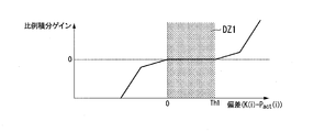
- FIGS. 15 and 16 are diagrams showing an example of the first dead zone DZ1 with respect to the current deviation.
- the first dead zone DZ1 only the positive side of the current deviation (lateral vehicle position P act (i) in comparison with the track point K (i) is a forward) Or may be set to be biased to the positive side.
- the “biased to the positive side” means that, for example, the center of gravity or the like of the area of the first dead zone DZ1 is present on the positive side of the current deviation.
- a region where the deviation is currently from zero to the threshold value Th1 (positive value) is set as the first dead zone DZ1. Further, in the example of FIG.
- a region from the threshold value Th2 (negative value) to the threshold value Th1 (positive value) is set as the first dead zone DZ1.
- the proportional gain and the integral gain are zero. Therefore, if the current deviation is within the first dead zone DZ1, the first correction amount derived by the proportional integral control unit 171 becomes zero or approximately zero.
- the proportional gain adjustment unit 181 sets the second dead zone DZ2 for the future deviation, and if the future deviation derived by the subtractor 170 is within the second dead zone DZ2, the future deviation falls within the second dead zone DZ2.
- the proportional gain in the proportional control unit 172 is reduced compared to the case where
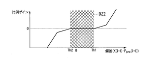
- FIGS. 17 and 18 are diagrams showing an example of the second dead zone DZ2 for the future deviation.
- the second dead zone DZ2 may be set to be only on the positive side or the positive side of the current deviation as in the case of the first dead zone DZ1.
- a region from the current deviation of zero to a threshold value Th1 (positive value) is set as the second dead zone DZ2.
- the region from the threshold value Th2 (negative value) to the threshold value Th1 (positive value) is set as the second dead zone DZ2.
- the proportional gain is zero.
- the second correction amount derived by the proportional control unit 172 becomes zero or almost zero.
- the sizes of the first dead zone DZ1 and the second dead zone DZ2 may be different from each other, or either one is set only on the positive side of the deviation, and the other is set on the positive side. It may be set biased.
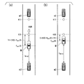
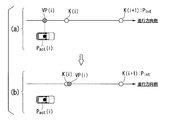
- FIG. 19 is a diagram showing an example of acceleration / deceleration control for each scene.
- FIG. 19A shows one scene in which the current deviation is not within the first dead zone DZ1.
- FIG. 19B shows one scene in which the current deviation is within the first dead zone DZ1.
- the trajectory point K (0) is located forward relative to the vehicle position P act (0) at the current time t 0 . That is, the trajectory point K (0) to be reached by the vehicle M at the present time t 0 has not been reached. Therefore, the acceleration / deceleration control unit 164 needs to control the driving force output device 200 to accelerate the host vehicle M.
- the first correction amount is added to the average speed, and the host vehicle M accelerates from the current average speed.
- the first correction amount decreases.
- the average speed derived by the first calculation unit 165 can be easily maintained without performing the acceleration control. Such processing can suppress frequent acceleration when the host vehicle M has not reached the track point K (0).
- the dead zone DZ is set as the deviation when the trajectory point K (i) is ahead of the own vehicle position P act (i), but the present invention is not limited to this.
- the dead zone DZ may be set as the deviation when the trajectory point K (i) is behind with respect to the position P act (i).
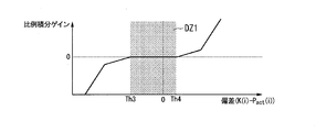
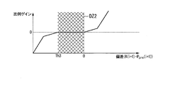
- FIGS. 20 and 21 are diagrams showing other examples of the first dead zone DZ1 with respect to the current deviation.
- the first dead zone DZ1 is only at the negative side of the current deviation (the side where the trajectory point K (i) is behind with respect to the vehicle position P act (i)) Or may be set to be biased to the negative side.
- a region where the current deviation is from the threshold value Th3 (negative value) to zero is set as the first dead zone DZ1.
- a region from the threshold value Th3 (negative value) to the threshold value Th4 (positive value) is set as the first dead zone DZ1.
- the second dead zone DZ2 may be set to be only the negative side of the current deviation or to be biased to the negative side.
- a region where the current deviation is from the threshold value Th3 (negative value) to zero is set as the second dead zone DZ2.
- the region from the threshold value Th3 (negative value) to the threshold value Th4 (positive value) is set as the second dead zone DZ2.
- the sizes of the first dead zone DZ1 and the second dead zone DZ2 may be different from each other, either one is set only on the negative side of the deviation, and the other is negative. It may be set biased to the side.
- FIG. 24 is a diagram showing an example of acceleration / deceleration control for each scene.
- FIG. 24A shows one scene in which the current deviation is not within the first dead zone DZ1.
- FIG. 24 (b) shows a scene in which the current deviation is within the first dead zone DZ1.
- the trajectory point K (0) is located behind the current vehicle position P act (0) at time t 0 . That is, the vehicle M is greater than the track point K (0) to be reached at the current time t 0. Therefore, the acceleration / deceleration control unit 164 needs to control the driving force output device 200 to decelerate the host vehicle M.
- the first correction amount is added to the average speed, and the host vehicle M decelerates from the current average speed.
- the first correction amount decreases.
- the average speed derived by the first calculation unit 165 can be easily maintained without performing the deceleration control. Such processing can suppress frequent deceleration when the host vehicle M exceeds the track point K (0).
- the proportional integral gain adjustment unit 180 described above includes a front vehicle traveling immediately in front of the host vehicle M and a follow on vehicle traveling immediately behind the host vehicle M.
- the area size of the first dead zone DZ1 to be currently set for the deviation may be changed based on the inter-vehicle distance between one or both and the host vehicle M.
- proportional gain adjustment section 181 may deviate in the future based on an inter-vehicle distance between host vehicle M and one or both of a preceding vehicle traveling immediately before host vehicle M and a following vehicle traveling immediately after host vehicle M.
- the area size of the second dead zone DZ2 to be set may be changed.
- FIG. 25 and FIG. 26 are diagrams for explaining the method of changing the area size of the dead zone DZ.
- the proportional integral gain adjustment unit 180 or the proportional gain adjustment unit 181 sets the dead zone which is set when the trajectory point K (i) is ahead of the own vehicle position P act (i).
- the threshold value Th1 on the positive side of DZ is increased on the positive side as the inter-vehicle distance to the following vehicle increases, and is decreased on the positive side as the inter-vehicle distance to the following vehicle decreases. Accordingly, when the inter-vehicle distance to the following vehicle is clogged, the acceleration / deceleration control unit 164 can perform acceleration frequently by narrowing the dead zone DZ in consideration of safety.
- the acceleration / deceleration control unit 164 can reduce the frequency of acceleration by widening the dead zone DZ when the inter-vehicle distance to the following vehicle is increased.
- the proportional integral gain adjustment unit 180 or the proportional gain adjustment unit 181 sets the trajectory point K (i) when the trajectory point K (i) is behind with respect to the vehicle position P act (i).
- the negative threshold value Th3 of the dead zone DZ is increased on the negative side as the inter-vehicle distance to the front vehicle increases, and is decreased on the negative side as the inter-vehicle distance to the front vehicle decreases. . Accordingly, when the inter-vehicle distance to the leading vehicle is clogged, the acceleration / deceleration control unit 164 can frequently perform deceleration by narrowing the dead zone DZ in consideration of safety.
- the acceleration / deceleration control unit 164 can reduce the frequency of deceleration by widening the dead zone DZ when the inter-vehicle distance to the leading vehicle is increased.
- FIG. 27 is a flow chart showing an example of the processing flow of the acceleration / deceleration control unit 164A in the second embodiment.
- the first operation unit 165 determines a trajectory point K that the vehicle M should reach from the plurality of trajectory points K included in the trajectory until the time corresponding to n seconds has elapsed from the current time t i. i) extract K (i + n) from i) and divide the path length of the orbit including K (i) from K (i) by time for n seconds to derive an average velocity (step S200 ).
- the fourth calculation unit 168 calculates A predicted position P pre (i + 1) at which the vehicle M is predicted to arrive at time t i + 1 after one second from the current time t i is derived (step S202).
- the subtractor 169 derives the current deviation obtained by subtracting the vehicle position P act (i) from the trajectory point K (i) extracted by the second operation unit 166 (step S204).
- the subtractor 170 derives a future deviation obtained by subtracting the predicted position P pre (i + 1) derived by the fourth operation unit 168 from the trajectory point K (i + 1) extracted by the third operation unit 167 (see FIG. Step S206).
- the proportional integral gain adjustment unit 180 determines whether the current deviation is within the first dead zone DZ1 (step S208). If the current deviation is within the first dead zone DZ1, the proportional integral control unit One or both of the proportional gain and the integral gain at 171 are decreased (step S210). On the other hand, if the current deviation is not within the first dead zone DZ1, the proportional integral gain adjustment unit 180 shifts the process to S212.
- the proportional-plus-integral control unit 171 multiplies the current deviation output from the subtractor 169 by a predetermined proportional gain, multiplies the time integration value of the current deviation by a predetermined integral gain, and adds these.
- the first correction amount is derived (step S212).
- the first output adjustment unit 173 performs filtering on the first correction amount (step S214).
- the proportional gain adjustment unit 181 determines whether or not the deviation is in the second dead zone DZ2 in the future (step S216), and if the deviation is in the second dead zone DZ2, the proportional control unit 172 The proportional gain is reduced (step S218). On the other hand, when the deviation is not within the second dead zone DZ2, the proportional gain adjustment unit 181 shifts the processing to S220.
- the proportional control unit 172 derives a second correction amount by multiplying the future deviation output from the subtractor 170 by a predetermined proportional gain (step S220).
- the second output adjustment unit 174 performs filtering on the second correction amount (step S222).
- the third output adjustment unit 175 performs filtering on the third correction amount obtained by adding the first correction amount and the second correction amount (step S224).
- the adder 177 adds the third correction amount adjusted by the third output adjustment unit 175 to the average velocity derived by the first calculation unit 165 to add itself to n seconds from the current time t i.
- the target velocity of the vehicle M is output (step S226).
- the dead zone DZ is set for any one or both of the future deviation and the present deviation, the occurrence of frequent acceleration and deceleration can be suppressed. As a result, the passenger's discomfort can be reduced while considering the safety of the vehicle.
- the region of the dead zone DZ is changed based on the inter-vehicle distance to the leading vehicle or the following vehicle, the occurrence of frequent acceleration and deceleration can be efficiently suppressed.
- the third embodiment will be described below.
- the third embodiment differs from the first and third embodiments in that the output gain of the third correction amount is adjusted when the speed of the host vehicle M is low.
- the following description will focus on the differences.
- FIG. 28 is a diagram showing an example of the configuration of the acceleration / deceleration control unit 164B in the third embodiment.
- the acceleration / deceleration control unit 164B includes, for example, a first operation unit 165, a second operation unit 166, a third operation unit 167, a fourth operation unit 168, subtractors 169 and 170, and a proportional integration control unit 171.
- the third gain adjustment unit 183 decreases the output gain for adjusting the third correction amount obtained by adding the first correction amount and the second correction amount.
- the multiplier 184 multiplies the output gain adjusted by the third gain adjustment unit 183 by the third correction amount output from the adder 176, and outputs the product to the adder 177.
- FIG. 29 is a view showing an example of the change of the output gain with respect to the speed v of the host vehicle M.
- the output gain decreases to 1 or less according to the decrease of the speed v. For this reason, when the host vehicle M gradually decelerates and stops, the third correction amount decreases, so the occurrence of acceleration and deceleration is further suppressed.
- the third correction amount is reduced according to the decrease in the speed of the host vehicle M, for example, frequent occurrence of acceleration and deceleration when the host vehicle M stops is suppressed. it can. Thereby, a smooth stop can be performed. Further, according to the third embodiment, since the third correction amount is increased as the speed of the host vehicle M increases, the host vehicle M can be smoothly accelerated from the stop state. As a result, the discomfort of the occupant can be reduced.
- a reference position (hereinafter referred to as a calculation reference position) is set on the track in a predetermined case, and acceleration / deceleration control is performed based on the calculation reference position. This is different from the embodiment of FIG. The following description will focus on the differences.
- FIG. 30 is a diagram showing an example of the configuration of the acceleration / deceleration control unit 164C in the fourth embodiment.
- the acceleration / deceleration control unit 164C further includes, for example, a fifth operation unit 185 in addition to the configuration of the acceleration / deceleration control unit 164 in the first embodiment described above.
- the fifth calculation unit 185 includes, for example, a setting necessity determination unit 185A and a calculation reference position setting unit 185B.
- Setting necessity determination unit 185A determines whether or not calculation reference position setting unit 185B described later needs to perform a predetermined process. For example, when the speed v of the host vehicle M is equal to or less than the speed threshold value Vth illustrated in FIG. 29 described above, the setting necessity determination unit 185A performs calculation in anticipation of a large current deviation and future deviation when traveling at low speeds.
- the reference position setting unit 185B performs predetermined processing.
- setting necessity determination section 185A has a distance from the track generated by track generation section 146 or an arbitrary track point K included in the track to vehicle position P act (i) at current time t i When it is separated by a predetermined distance or more, it may be determined that the host vehicle M deviates from the track, and the arithmetic reference position setting unit 185B may perform predetermined processing.
- the calculation reference position setting unit 185B sets the calculation reference position VP (i) on the trajectory generated by the trajectory generation unit 146 based on the vehicle position P act (i) at the current time t i .
- FIG. 31 is a diagram for describing a setting method of the calculation reference position VP (i).
- the calculation reference position setting unit 185B sets, as a provisional target position P int , an orbital point K (i + 1) corresponding to time t i + 1 which is one second elapsed from the current time t i .
- the provisional target position P int is a position temporarily referred to as a target position when returning from the vehicle position P act (i) onto the trajectory.
- the calculation reference position setting unit 185B selects one of a plurality of tangents to a trajectory connecting each trajectory point K up to the provisional target position P int with a smooth curve (for example, a spline curve).
- a tangent line crossing the perpendicular passing through the vehicle position P act (i) at the contact point is derived, and the calculation reference position VP (i) is set at the intersection point (contact point) with the perpendicular on the tangent line.
- the calculation reference position setting unit 185B outputs the set calculation reference position VP (i) to the first calculation unit 165, the second calculation unit 166, and the fourth calculation unit 168.
- the first operation unit 165 treats the output operation reference position VP (i) as an orbital point K (i) corresponding to the current time t i, and calculates from the operation reference position VP (i) to K
- the path length of the trajectory containing (i + n) is divided by the time of n seconds to derive the average velocity.
- the second operation unit 166 handles the output operation reference position VP (i) as the extracted trajectory point K (i).
- the fourth operation unit 168 derives the predicted position P pre (i + 1) based on the operation reference position VP (i). As a result, even when the host vehicle M deviates from the track, the acceleration / deceleration control unit 164C projects the deviated position onto the track, so that the average speed, the current deviation, and the future deviation are It can be derived.
- the calculation reference position setting unit 185B may set the trajectory point K (i + j) corresponding to the time t i + j after j (j> 1) seconds from the current time t i as the provisional target position P int. .
- the calculation reference position setting unit 185B substitutes, for example, the vehicle position P act at the contact point with the track among a plurality of tangents in contact with the track instead of the setting method of the calculation reference position VP (i) described above.
- a tangent line intersecting the perpendicular line passing through (i) may be derived, and the trajectory point K closest to the intersection point (contact point) with the perpendicular line on the tangent line may be set as the calculation reference position VP (i).
- the calculation reference position setting unit 185B selects one of the trajectory point K (i) and the trajectory point K (i + 1). The trajectory point K (i) closer to the intersection is set as the calculation reference position VP (i).
- the calculation reference position setting unit 185B may correct the calculation reference position VP (i) set on the trajectory based on the positional relationship with the trajectory point K (i) corresponding to the current time t i .
- FIG. 32 schematically shows an example of the correction of the calculation reference position VP (i).
- the calculation reference position VP (i) may be changed to the same position as the orbital point K (i) or a position on the front side of the orbital point K (i).
- the average speed and the current deviation become smaller, it is possible to suppress the rapid increase of the target speed and to prevent the rapid acceleration of the host vehicle M.
- the calculation reference position setting unit 185B corrects the calculation reference position VP (i) set on the orbit based on the positional relationship with the provisional target position P int (for example, the next time point K (i + 1)).
- FIG. 33 schematically shows another example of the correction of the calculation reference position VP (i).
- a limit position LIM to which the calculation reference position VP (i) can be set is set in the trajectory based on the provisional target position P int .
- the calculation reference position setting unit 185B sets the calculation reference position VP (i) at the limit position, as shown in FIG. It may be changed to the same position as LIM or to a position on the front side of the limit position LIM.
- FIG. 34 is a flow chart showing an example of the flow of processing of the fifth arithmetic unit 185 in the fourth embodiment.
- setting necessity determination section 185A determines whether or not own vehicle M deviates from the track (step S300). If the host vehicle M does not deviate from the track, the setting necessity determination unit 185A determines whether the speed v of the host vehicle M is less than or equal to the speed threshold Vth (step S302). If the speed v of the host vehicle M is not equal to or less than the speed threshold Vth, the acceleration / deceleration control unit 164C ends the processing of this flowchart. Note that one of the process of S300 and the process of S302 may be omitted.
- the calculation reference position setting unit 185B determines that the host vehicle position P act at the current time t i Based on i), the calculation reference position VP (i) is set on the trajectory generated by the trajectory generation unit 146 (step S304).
- the calculation reference position setting unit 185B determines whether the set calculation reference position VP (i) is positioned behind the trajectory point K (i) (step S306). When the calculation reference position VP (i) is located behind the trajectory point K (i), the calculation reference position setting unit 185B sets the calculation reference position VP (i) to the same position as the trajectory point K (i), or Correction is made to a position on the front side of the trajectory point K (i) (step S308). On the other hand, if the calculation reference position VP (i) is not located behind the trajectory point K (i), the calculation reference position setting unit 185B ends the processing of this flowchart.
- the first calculation unit 165, the second calculation unit 166, and the fourth calculation unit 168 calculate the calculation reference position VP
- various calculation processes are performed based on i)
- various calculation processes are performed based on the vehicle position P act (i) at the current time t i .
- the first operation unit 165 derives an average velocity by dividing the path length of the trajectory including the trajectory point K (i + n) from the operation reference position VP (i) by the time for n seconds.
- the second operation unit 166 handles the operation reference position VP (i) as the extracted orbital point K (i).
- the subtractor 169 derives a deviation regarding the vehicle traveling direction obtained by subtracting the calculation reference position VP (i) from the track point K (i) corresponding to the current time t i as the present deviation.
- Fourth operation unit 168 calculates current reference position VP (i) and speed v and acceleration ⁇ of host vehicle M detected by vehicle sensor 60 at time t i + 1 at which one second has passed from current time t i .
- a predicted position P pre (i + 1) at which the host vehicle M is predicted to arrive is derived.
- the fifth calculation unit 185 is positioned closest to the position of the vehicle M recognized by the vehicle position recognition unit 140. set the operation reference position VP (i), the first operation unit 165, from among a plurality of track points K included in the track, n seconds worth of time from the current time t i (first predetermined time)
- the trajectory point K (i + n) corresponding to the elapsed time in the future is extracted, and the vehicle M along the trajectory is calculated based on the length of the trajectory from the calculation reference position VP (i) to the trajectory point K (i + n) Deriving the target speed when driving. Therefore, for example, when the vehicle M deviates from the track, or when the speed of the vehicle M becomes equal to or less than the speed threshold Vth and the current deviation or the deviation becomes large, the speed control of the vehicle is accurately performed along the track. be able to.
- the fifth embodiment will be described below.
- the fifth embodiment is different from the first to fourth embodiments in that the target speed to be output is limited without performing the correction process of the calculation reference position VP (i).
- the following description will focus on the differences.
- FIG. 35 is a diagram showing an example of the configuration of the acceleration / deceleration control unit 164D in the fifth embodiment.
- the acceleration / deceleration control unit 164D further includes, for example, a fourth gain adjustment unit 186 and a multiplier 187 in addition to the configuration of the acceleration / deceleration control unit 164 in the fourth embodiment described above.
- the fourth gain adjustment unit 186 calculates the target velocity output from the adder 177 as the velocity v of the host vehicle M decreases, instead of the calculation reference position setting unit 185B correcting the calculation reference position VP (i). Decrease the output gain for adjustment.
- the multiplier 187 multiplies the output gain adjusted by the fourth gain adjustment unit 186 by the target speed output from the adder 177 and outputs the product.
- the calculation reference position VP (i) is set behind the trajectory point K (i), and the distance from the calculation reference position VP (i) to the trajectory point K (i + n) after n seconds is actually When it becomes longer than the distance to drive
- the sixth embodiment will be described below.
- an automatic operation mode is performed in which events in the action plan are changed or executed.
- This embodiment differs from the first to fifth embodiments in that switching to another automatic operation mode or manual operation mode is performed. The following description will focus on the differences.
- the automatic driving mode control unit 130 in the sixth embodiment is a mode of automatic driving that is currently executed when the host vehicle M deviates from the track or when the speed v of the host vehicle M becomes equal to or lower than the speed threshold Vth.
- a mode with a lower degree of automatic operation For example, when mode A without a duty to monitor surroundings is being executed, the automatic operation mode control unit 130 changes the automatic operation mode to be executed to mode B or mode C.
- the vehicle occupant since the vehicle occupant is required to monitor the surroundings, the vehicle occupant can be urged to direct the attention of the vehicle occupant to the periphery of the host vehicle M.
- the vehicle occupant can recognize that the host vehicle M is traveling off the track, and can operate the host vehicle M manually by operating the changeover switch 80 as appropriate.
- the action plan generation unit 144 in the sixth embodiment determines that the vehicle M deviates from the track or the velocity v of the vehicle M becomes equal to or less than the velocity threshold Vth.
- the current event may be changed to an event that does not require (or less) acceleration control.
- the action plan generation unit 144 changes the lane change event to a lane keep event or the like.
- the traveling mode during the lane keeping event is determined as constant speed traveling without acceleration and deceleration. This makes it easy to maintain the automatic operation mode even in a situation where the deviation becomes large.
- the switching control unit 150 in the sixth embodiment performs the case where the host vehicle M deviates from the track or the speed v of the host vehicle M becomes equal to or lower than the speed threshold Vth regardless of the operation of the switch 80. By switching the automatic driving mode to the manual driving mode, the operation right of the host vehicle M can be delegated to the vehicle occupant.
- steering control unit 164 acceleration / deceleration control unit 165: first operation unit 166: second operation unit 167: third operation unit 168: fourth operation unit 169, 170
Landscapes
- Engineering & Computer Science (AREA)
- Radar, Positioning & Navigation (AREA)
- Remote Sensing (AREA)
- Automation & Control Theory (AREA)
- Transportation (AREA)
- Mechanical Engineering (AREA)
- Physics & Mathematics (AREA)
- General Physics & Mathematics (AREA)
- Human Computer Interaction (AREA)
- Control Of Driving Devices And Active Controlling Of Vehicle (AREA)
- Traffic Control Systems (AREA)
- Navigation (AREA)
- Control Of Position, Course, Altitude, Or Attitude Of Moving Bodies (AREA)
- Aviation & Aerospace Engineering (AREA)
Abstract
L'invention concerne un système de commande de véhicule comprenant : une unité de reconnaissance de position qui reconnaît la position du véhicule ; une unité de génération de trajet qui génère un trajet dans lequel de multiples positions cibles futures devant être atteintes par le véhicule sont incluses selon une série chronologique ; une unité de définition de position de référence de calcul qui, dans le trajet susmentionné, définit une position de référence calculée au niveau de la position la plus proche de la position du véhicule reconnue par l'unité de reconnaissance de position ; et une unité de commande de déplacement qui, à partir de multiples positions cibles comprises dans le trajet, extrait une première position cible correspondant au futur moment où une durée prescrite se sera écoulée à partir du moment où la reconnaissance de position du véhicule a été mise en œuvre, et qui, sur la base de la longueur du trajet de la position de référence de calcul à la première position cible, calcule la vitesse cible pour que le véhicule se déplace le long du trajet.
Priority Applications (3)
| Application Number | Priority Date | Filing Date | Title |
|---|---|---|---|
| CN201780028245.7A CN109154820B (zh) | 2016-05-16 | 2017-05-01 | 车辆控制系统、车辆控制方法及存储介质 |
| JP2018518211A JP6544878B2 (ja) | 2016-05-16 | 2017-05-01 | 車両制御システム、車両制御方法、および車両制御プログラム |
| US16/099,725 US20190155293A1 (en) | 2016-05-16 | 2017-05-01 | Vehicle control system, vehicle control method and vehicle control program |
Applications Claiming Priority (2)
| Application Number | Priority Date | Filing Date | Title |
|---|---|---|---|
| JP2016-098049 | 2016-05-16 | ||
| JP2016098049 | 2016-05-16 |
Publications (1)
| Publication Number | Publication Date |
|---|---|
| WO2017199751A1 true WO2017199751A1 (fr) | 2017-11-23 |
Family
ID=60325911
Family Applications (1)
| Application Number | Title | Priority Date | Filing Date |
|---|---|---|---|
| PCT/JP2017/017149 Ceased WO2017199751A1 (fr) | 2016-05-16 | 2017-05-01 | Système de commande de véhicule, procédé de commande de véhicule et programme de commande de véhicule |
Country Status (4)
| Country | Link |
|---|---|
| US (1) | US20190155293A1 (fr) |
| JP (1) | JP6544878B2 (fr) |
| CN (1) | CN109154820B (fr) |
| WO (1) | WO2017199751A1 (fr) |
Cited By (12)
| Publication number | Priority date | Publication date | Assignee | Title |
|---|---|---|---|---|
| CN110018689A (zh) * | 2019-05-15 | 2019-07-16 | 福州大学 | 一种基于动态窗口的多虚拟目标点全局动态路径规划算法 |
| JP2020015489A (ja) * | 2018-06-06 | 2020-01-30 | ホンダ リサーチ インスティテュート ヨーロッパ ゲーエムベーハーHonda Research Institute Europe GmbH | 自車両の将来挙動および関連する軌道を決定することにより、自車両の操作者が当該自車両を制御するのを支援する方法およびシステム |
| WO2020183988A1 (fr) * | 2019-03-13 | 2020-09-17 | 日立建機株式会社 | Engin de chantier |
| WO2020256070A1 (fr) * | 2019-06-21 | 2020-12-24 | 愛知製鋼株式会社 | Procédé de commande et système de commande pour véhicule |
| JP2021031027A (ja) * | 2019-08-29 | 2021-03-01 | トヨタ自動車株式会社 | 車両制御システム |
| WO2021145178A1 (fr) * | 2020-01-17 | 2021-07-22 | 株式会社デンソー | Dispositif de génération de trajectoire, procédé de génération de trajectoire et programme de génération de trajectoire |
| CN113282074A (zh) * | 2020-02-03 | 2021-08-20 | 奥迪股份公司 | 自动驾驶车辆基于轨迹自检的应急系统和应急方法 |
| WO2021199964A1 (fr) * | 2020-03-31 | 2021-10-07 | 株式会社デンソー | Dispositif de commande de présentation, programme de commande de présentation, système de commande de conduite automatisée et procédé de commande de conduite automatisée |
| JP2021160708A (ja) * | 2020-03-31 | 2021-10-11 | 株式会社デンソー | 提示制御装置、提示制御プログラム、自動走行制御システムおよび自動走行制御プログラム |
| JP2022168406A (ja) * | 2021-04-26 | 2022-11-08 | 三菱電機株式会社 | 走行計画生成装置 |
| WO2022249218A1 (fr) * | 2021-05-24 | 2022-12-01 | 三菱電機株式会社 | Dispositif de planification de trajectoire |
| CN116323351A (zh) * | 2020-10-15 | 2023-06-23 | 罗伯特·博世有限公司 | 用于生成横向偏移轨迹的方法 |
Families Citing this family (13)
| Publication number | Priority date | Publication date | Assignee | Title |
|---|---|---|---|---|
| JP6371271B2 (ja) * | 2015-11-27 | 2018-08-08 | 株式会社アドヴィックス | 車両用制動装置 |
| WO2018117631A1 (fr) * | 2016-12-21 | 2018-06-28 | Samsung Electronics Co., Ltd. | Appareil électronique et procédé d'exploitation de celui-ci |
| JP7052786B2 (ja) * | 2018-12-14 | 2022-04-12 | 株式会社デンソー | 表示制御装置および表示制御プログラム |
| WO2020152977A1 (fr) * | 2019-01-21 | 2020-07-30 | 日立オートモティブシステムズ株式会社 | Dispositif de commande de véhicule, procédé de commande de véhicule et système de commande de véhicule |
| WO2020201797A1 (fr) * | 2019-03-29 | 2020-10-08 | 日産自動車株式会社 | Procédé de commande de véhicule et dispositif de commande de véhicule |
| JP7238670B2 (ja) * | 2019-07-23 | 2023-03-14 | トヨタ自動車株式会社 | 画像表示装置 |
| JP7156238B2 (ja) * | 2019-10-15 | 2022-10-19 | トヨタ自動車株式会社 | 車両制御システム |
| CN114730004B (zh) * | 2019-11-29 | 2025-03-18 | 三菱电机株式会社 | 物体识别装置和物体识别方法 |
| CN112015203B (zh) * | 2020-09-07 | 2024-04-02 | 深圳大漠大智控技术有限公司 | 一种无人机集群轨迹跟踪方法及系统 |
| WO2022144958A1 (fr) * | 2020-12-28 | 2022-07-07 | 本田技研工業株式会社 | Dispositif de commande de véhicule, procédé de commande de véhicule et programme |
| JP7186210B2 (ja) * | 2020-12-28 | 2022-12-08 | 本田技研工業株式会社 | 車両制御装置、車両制御方法、およびプログラム |
| JP7177862B2 (ja) * | 2021-01-04 | 2022-11-24 | 本田技研工業株式会社 | 位置決定装置 |
| CN115042820A (zh) * | 2022-07-11 | 2022-09-13 | 北京主线科技有限公司 | 自动驾驶车辆控制方法、装置、设备及存储介质 |
Citations (3)
| Publication number | Priority date | Publication date | Assignee | Title |
|---|---|---|---|---|
| JPS5042291A (fr) * | 1973-08-17 | 1975-04-17 | ||
| JP2007203860A (ja) * | 2006-02-01 | 2007-08-16 | Xanavi Informatics Corp | 車両速度制御装置および同装置における目標速度設定方法ならびにプログラム |
| JP2016064746A (ja) * | 2014-09-25 | 2016-04-28 | 富士重工業株式会社 | 車両制御装置 |
Family Cites Families (26)
| Publication number | Priority date | Publication date | Assignee | Title |
|---|---|---|---|---|
| BRPI0513156B1 (pt) * | 2004-08-06 | 2017-12-26 | Honda Motor Co., Ltd. | Control device for a vehicle equipped with a variable output device manipulated to drive ?? |
| JP4099723B2 (ja) * | 2005-07-12 | 2008-06-11 | 村田機械株式会社 | 搬送台車システム |
| US8352147B2 (en) * | 2007-11-26 | 2013-01-08 | Equos Research Co., Ltd. | Vehicle control device |
| JP4934167B2 (ja) * | 2009-06-18 | 2012-05-16 | クラリオン株式会社 | 位置検出装置および位置検出プログラム |
| JP5042291B2 (ja) * | 2009-10-12 | 2012-10-03 | 有限会社信建 | 支柱立て起し機具 |
| SE535422C2 (sv) * | 2010-06-23 | 2012-07-31 | Scania Cv Ab | Metod och modul för att styra ett fordons hastighet |
| JP5501260B2 (ja) * | 2011-02-03 | 2014-05-21 | ジヤトコ株式会社 | 車両の制御装置 |
| JP5589877B2 (ja) * | 2011-02-09 | 2014-09-17 | トヨタ自動車株式会社 | 車両用情報処理装置 |
| WO2012153629A1 (fr) * | 2011-05-12 | 2012-11-15 | 株式会社Ihi | Dispositif et procédé pour contrôler la prédiction du mouvement |
| EP2743901B1 (fr) * | 2011-08-10 | 2018-10-31 | Toyota Jidosha Kabushiki Kaisha | Dispositif d'assistance à la conduite |
| JP5578331B2 (ja) * | 2011-12-26 | 2014-08-27 | トヨタ自動車株式会社 | 車両の走行軌跡制御装置 |
| JP5926558B2 (ja) * | 2011-12-29 | 2016-05-25 | クラリオン株式会社 | 車両用情報システムおよびサーバ装置 |
| WO2014024336A1 (fr) * | 2012-08-09 | 2014-02-13 | トヨタ自動車株式会社 | Appareil de détection d'objet et appareil d'aide à la conduite |
| JP5754427B2 (ja) * | 2012-08-27 | 2015-07-29 | トヨタ自動車株式会社 | 車両制御システム |
| JP5527382B2 (ja) * | 2012-10-12 | 2014-06-18 | トヨタ自動車株式会社 | 走行支援システム及び制御装置 |
| US9409575B2 (en) * | 2012-11-26 | 2016-08-09 | Honda Motor Co., Ltd. | Vehicle control device |
| JP6000178B2 (ja) * | 2013-03-29 | 2016-09-28 | 本田技研工業株式会社 | 車両用変速装置 |
| JP5917472B2 (ja) * | 2013-11-08 | 2016-05-18 | 本田技研工業株式会社 | 運転支援装置 |
| US9607230B2 (en) * | 2014-04-16 | 2017-03-28 | Honda Motor Co., Ltd. | Mobile object control apparatus and target object detecting apparatus |
| JP6067623B2 (ja) * | 2014-06-27 | 2017-01-25 | 本田技研工業株式会社 | 走行制御装置 |
| JP6201927B2 (ja) * | 2014-08-01 | 2017-09-27 | トヨタ自動車株式会社 | 車両制御装置 |
| JP6022517B2 (ja) * | 2014-09-12 | 2016-11-09 | アイシン精機株式会社 | 車両の制御装置 |
| EP3018026B1 (fr) * | 2014-11-06 | 2019-05-15 | Veoneer Sweden AB | Procédé de prédiction de trajet d'un véhicule |
| CN104991580A (zh) * | 2015-06-18 | 2015-10-21 | 奇瑞汽车股份有限公司 | 无人驾驶车辆的控制系统及其控制方法 |
| DE102015215929A1 (de) * | 2015-08-20 | 2017-02-23 | Volkswagen Aktiengesellschaft | Vorrichtungen, Verfahren und Computerprogramm zum Bereitstellen von Information über eine voraussichtliche Fahrintention |
| JP6558239B2 (ja) * | 2015-12-22 | 2019-08-14 | アイシン・エィ・ダブリュ株式会社 | 自動運転支援システム、自動運転支援方法及びコンピュータプログラム |
-
2017
- 2017-05-01 WO PCT/JP2017/017149 patent/WO2017199751A1/fr not_active Ceased
- 2017-05-01 JP JP2018518211A patent/JP6544878B2/ja not_active Expired - Fee Related
- 2017-05-01 CN CN201780028245.7A patent/CN109154820B/zh not_active Expired - Fee Related
- 2017-05-01 US US16/099,725 patent/US20190155293A1/en not_active Abandoned
Patent Citations (3)
| Publication number | Priority date | Publication date | Assignee | Title |
|---|---|---|---|---|
| JPS5042291A (fr) * | 1973-08-17 | 1975-04-17 | ||
| JP2007203860A (ja) * | 2006-02-01 | 2007-08-16 | Xanavi Informatics Corp | 車両速度制御装置および同装置における目標速度設定方法ならびにプログラム |
| JP2016064746A (ja) * | 2014-09-25 | 2016-04-28 | 富士重工業株式会社 | 車両制御装置 |
Cited By (22)
| Publication number | Priority date | Publication date | Assignee | Title |
|---|---|---|---|---|
| JP7143250B2 (ja) | 2018-06-06 | 2022-09-28 | ホンダ リサーチ インスティテュート ヨーロッパ ゲーエムベーハー | 自車両の将来挙動および関連する軌道を決定することにより、自車両の操作者が当該自車両を制御するのを支援する方法およびシステム |
| JP2020015489A (ja) * | 2018-06-06 | 2020-01-30 | ホンダ リサーチ インスティテュート ヨーロッパ ゲーエムベーハーHonda Research Institute Europe GmbH | 自車両の将来挙動および関連する軌道を決定することにより、自車両の操作者が当該自車両を制御するのを支援する方法およびシステム |
| WO2020183988A1 (fr) * | 2019-03-13 | 2020-09-17 | 日立建機株式会社 | Engin de chantier |
| CN110018689A (zh) * | 2019-05-15 | 2019-07-16 | 福州大学 | 一种基于动态窗口的多虚拟目标点全局动态路径规划算法 |
| JP7406130B2 (ja) | 2019-06-21 | 2023-12-27 | 愛知製鋼株式会社 | 車両用の制御方法及び制御システム |
| JPWO2020256070A1 (fr) * | 2019-06-21 | 2020-12-24 | ||
| WO2020256070A1 (fr) * | 2019-06-21 | 2020-12-24 | 愛知製鋼株式会社 | Procédé de commande et système de commande pour véhicule |
| CN113993762A (zh) * | 2019-06-21 | 2022-01-28 | 爱知制钢株式会社 | 车辆用的控制方法以及控制系统 |
| JP2021031027A (ja) * | 2019-08-29 | 2021-03-01 | トヨタ自動車株式会社 | 車両制御システム |
| JP7136054B2 (ja) | 2019-08-29 | 2022-09-13 | トヨタ自動車株式会社 | 車両制御システム |
| WO2021145178A1 (fr) * | 2020-01-17 | 2021-07-22 | 株式会社デンソー | Dispositif de génération de trajectoire, procédé de génération de trajectoire et programme de génération de trajectoire |
| JP2021112967A (ja) * | 2020-01-17 | 2021-08-05 | 株式会社デンソー | 軌道生成装置、軌道生成方法、および軌道生成プログラム |
| CN113282074A (zh) * | 2020-02-03 | 2021-08-20 | 奥迪股份公司 | 自动驾驶车辆基于轨迹自检的应急系统和应急方法 |
| JP2021160708A (ja) * | 2020-03-31 | 2021-10-11 | 株式会社デンソー | 提示制御装置、提示制御プログラム、自動走行制御システムおよび自動走行制御プログラム |
| JP7363833B2 (ja) | 2020-03-31 | 2023-10-18 | 株式会社デンソー | 提示制御装置、提示制御プログラム、自動走行制御システムおよび自動走行制御プログラム |
| WO2021199964A1 (fr) * | 2020-03-31 | 2021-10-07 | 株式会社デンソー | Dispositif de commande de présentation, programme de commande de présentation, système de commande de conduite automatisée et procédé de commande de conduite automatisée |
| CN116323351A (zh) * | 2020-10-15 | 2023-06-23 | 罗伯特·博世有限公司 | 用于生成横向偏移轨迹的方法 |
| JP2022168406A (ja) * | 2021-04-26 | 2022-11-08 | 三菱電機株式会社 | 走行計画生成装置 |
| JP7258074B2 (ja) | 2021-04-26 | 2023-04-14 | 三菱電機株式会社 | 走行計画生成装置 |
| WO2022249218A1 (fr) * | 2021-05-24 | 2022-12-01 | 三菱電機株式会社 | Dispositif de planification de trajectoire |
| JPWO2022249218A1 (fr) * | 2021-05-24 | 2022-12-01 | ||
| JP7599558B2 (ja) | 2021-05-24 | 2024-12-13 | 三菱電機株式会社 | 軌道計画装置 |
Also Published As
| Publication number | Publication date |
|---|---|
| US20190155293A1 (en) | 2019-05-23 |
| CN109154820B (zh) | 2021-10-22 |
| CN109154820A (zh) | 2019-01-04 |
| JPWO2017199751A1 (ja) | 2018-12-27 |
| JP6544878B2 (ja) | 2019-07-17 |
Similar Documents
| Publication | Publication Date | Title |
|---|---|---|
| JP6544878B2 (ja) | 車両制御システム、車両制御方法、および車両制御プログラム | |
| JP6590270B2 (ja) | 車両制御システム、車両制御方法、および車両制御プログラム | |
| JP6569186B2 (ja) | 車両制御装置、車両制御方法、および車両制御プログラム | |
| JP6598127B2 (ja) | 車両制御システム、車両制御方法、および車両制御プログラム | |
| JP6768787B2 (ja) | 車両制御システム、車両制御方法、および車両制御プログラム | |
| JP6582319B2 (ja) | 車両制御システム、車両制御方法、および車両制御プログラム | |
| JP6246844B2 (ja) | 車両制御システム、車両制御方法、および車両制御プログラム | |
| JP6338159B2 (ja) | 交通状況推定装置、車両制御システム、経路誘導装置、交通状況推定方法、および交通状況推定プログラム | |
| JP6387548B2 (ja) | 車両制御システム、車両制御方法、および車両制御プログラム | |
| JP6344695B2 (ja) | 車両制御装置、車両制御方法、および車両制御プログラム | |
| JP6745334B2 (ja) | 車両制御システム、車両制御方法、および車両制御プログラム | |
| JP6537208B2 (ja) | 車両制御装置、車両制御方法、および車両制御プログラム | |
| JP6540983B2 (ja) | 車両制御システム、車両制御方法、および車両制御プログラム | |
| WO2017138513A1 (fr) | Dispositif de commande de véhicule, procédé de commande de véhicule, et programme de commande de véhicule | |
| WO2017159493A1 (fr) | Dispositif de commande de véhicule, procédé de commande de véhicule et programme de commande de véhicule | |
| WO2017168517A1 (fr) | Dispositif de commande de véhicule, procédé de commande de véhicule, et programme de commande de véhicule | |
| JP2017144886A (ja) | 車両制御装置、車両制御方法、および車両制御プログラム | |
| JP2017146794A (ja) | 車両制御装置、車両制御方法、および車両制御プログラム | |
| JP2018037100A (ja) | 車両制御システム、車両制御方法、および車両制御プログラム | |
| JP6650331B2 (ja) | 車両制御システム、車両制御方法、および車両制御プログラム | |
| JP2017213936A (ja) | 車両制御システム、車両制御方法、および車両制御プログラム |
Legal Events
| Date | Code | Title | Description |
|---|---|---|---|
| WWE | Wipo information: entry into national phase |
Ref document number: 2018518211 Country of ref document: JP |
|
| NENP | Non-entry into the national phase |
Ref country code: DE |
|
| 121 | Ep: the epo has been informed by wipo that ep was designated in this application |
Ref document number: 17799181 Country of ref document: EP Kind code of ref document: A1 |
|
| 122 | Ep: pct application non-entry in european phase |
Ref document number: 17799181 Country of ref document: EP Kind code of ref document: A1 |