WO2017199801A1 - 能動型振動制御装置 - Google Patents
能動型振動制御装置 Download PDFInfo
- Publication number
- WO2017199801A1 WO2017199801A1 PCT/JP2017/017633 JP2017017633W WO2017199801A1 WO 2017199801 A1 WO2017199801 A1 WO 2017199801A1 JP 2017017633 W JP2017017633 W JP 2017017633W WO 2017199801 A1 WO2017199801 A1 WO 2017199801A1
- Authority
- WO
- WIPO (PCT)
- Prior art keywords
- magnetic
- vibration control
- viscoelastic elastomer
- control device
- active vibration
- Prior art date
- Legal status (The legal status is an assumption and is not a legal conclusion. Google has not performed a legal analysis and makes no representation as to the accuracy of the status listed.)
- Ceased
Links
Images






Classifications
-
- F—MECHANICAL ENGINEERING; LIGHTING; HEATING; WEAPONS; BLASTING
- F16—ENGINEERING ELEMENTS AND UNITS; GENERAL MEASURES FOR PRODUCING AND MAINTAINING EFFECTIVE FUNCTIONING OF MACHINES OR INSTALLATIONS; THERMAL INSULATION IN GENERAL
- F16F—SPRINGS; SHOCK-ABSORBERS; MEANS FOR DAMPING VIBRATION
- F16F1/00—Springs
- F16F1/36—Springs made of rubber or other material having high internal friction, e.g. thermoplastic elastomers
- F16F1/3605—Springs made of rubber or other material having high internal friction, e.g. thermoplastic elastomers characterised by their material
- F16F1/361—Springs made of rubber or other material having high internal friction, e.g. thermoplastic elastomers characterised by their material comprising magneto-rheological elastomers [MR]
-
- F—MECHANICAL ENGINEERING; LIGHTING; HEATING; WEAPONS; BLASTING
- F16—ENGINEERING ELEMENTS AND UNITS; GENERAL MEASURES FOR PRODUCING AND MAINTAINING EFFECTIVE FUNCTIONING OF MACHINES OR INSTALLATIONS; THERMAL INSULATION IN GENERAL
- F16F—SPRINGS; SHOCK-ABSORBERS; MEANS FOR DAMPING VIBRATION
- F16F15/00—Suppression of vibrations in systems; Means or arrangements for avoiding or reducing out-of-balance forces, e.g. due to motion
- F16F15/02—Suppression of vibrations of non-rotating, e.g. reciprocating systems; Suppression of vibrations of rotating systems by use of members not moving with the rotating systems
- F16F15/03—Suppression of vibrations of non-rotating, e.g. reciprocating systems; Suppression of vibrations of rotating systems by use of members not moving with the rotating systems using magnetic or electromagnetic means
-
- B—PERFORMING OPERATIONS; TRANSPORTING
- B60—VEHICLES IN GENERAL
- B60K—ARRANGEMENT OR MOUNTING OF PROPULSION UNITS OR OF TRANSMISSIONS IN VEHICLES; ARRANGEMENT OR MOUNTING OF PLURAL DIVERSE PRIME-MOVERS IN VEHICLES; AUXILIARY DRIVES FOR VEHICLES; INSTRUMENTATION OR DASHBOARDS FOR VEHICLES; ARRANGEMENTS IN CONNECTION WITH COOLING, AIR INTAKE, GAS EXHAUST OR FUEL SUPPLY OF PROPULSION UNITS IN VEHICLES
- B60K5/00—Arrangement or mounting of internal-combustion or jet-propulsion units
- B60K5/12—Arrangement of engine supports
-
- B—PERFORMING OPERATIONS; TRANSPORTING
- B60—VEHICLES IN GENERAL
- B60K—ARRANGEMENT OR MOUNTING OF PROPULSION UNITS OR OF TRANSMISSIONS IN VEHICLES; ARRANGEMENT OR MOUNTING OF PLURAL DIVERSE PRIME-MOVERS IN VEHICLES; AUXILIARY DRIVES FOR VEHICLES; INSTRUMENTATION OR DASHBOARDS FOR VEHICLES; ARRANGEMENTS IN CONNECTION WITH COOLING, AIR INTAKE, GAS EXHAUST OR FUEL SUPPLY OF PROPULSION UNITS IN VEHICLES
- B60K5/00—Arrangement or mounting of internal-combustion or jet-propulsion units
- B60K5/12—Arrangement of engine supports
- B60K5/1208—Resilient supports
-
- F—MECHANICAL ENGINEERING; LIGHTING; HEATING; WEAPONS; BLASTING
- F16—ENGINEERING ELEMENTS AND UNITS; GENERAL MEASURES FOR PRODUCING AND MAINTAINING EFFECTIVE FUNCTIONING OF MACHINES OR INSTALLATIONS; THERMAL INSULATION IN GENERAL
- F16F—SPRINGS; SHOCK-ABSORBERS; MEANS FOR DAMPING VIBRATION
- F16F15/00—Suppression of vibrations in systems; Means or arrangements for avoiding or reducing out-of-balance forces, e.g. due to motion
- F16F15/02—Suppression of vibrations of non-rotating, e.g. reciprocating systems; Suppression of vibrations of rotating systems by use of members not moving with the rotating systems
-
- F—MECHANICAL ENGINEERING; LIGHTING; HEATING; WEAPONS; BLASTING
- F16—ENGINEERING ELEMENTS AND UNITS; GENERAL MEASURES FOR PRODUCING AND MAINTAINING EFFECTIVE FUNCTIONING OF MACHINES OR INSTALLATIONS; THERMAL INSULATION IN GENERAL
- F16F—SPRINGS; SHOCK-ABSORBERS; MEANS FOR DAMPING VIBRATION
- F16F15/00—Suppression of vibrations in systems; Means or arrangements for avoiding or reducing out-of-balance forces, e.g. due to motion
- F16F15/02—Suppression of vibrations of non-rotating, e.g. reciprocating systems; Suppression of vibrations of rotating systems by use of members not moving with the rotating systems
- F16F15/04—Suppression of vibrations of non-rotating, e.g. reciprocating systems; Suppression of vibrations of rotating systems by use of members not moving with the rotating systems using elastic means
- F16F15/08—Suppression of vibrations of non-rotating, e.g. reciprocating systems; Suppression of vibrations of rotating systems by use of members not moving with the rotating systems using elastic means with rubber springs ; with springs made of rubber and metal
-
- F—MECHANICAL ENGINEERING; LIGHTING; HEATING; WEAPONS; BLASTING
- F16—ENGINEERING ELEMENTS AND UNITS; GENERAL MEASURES FOR PRODUCING AND MAINTAINING EFFECTIVE FUNCTIONING OF MACHINES OR INSTALLATIONS; THERMAL INSULATION IN GENERAL
- F16F—SPRINGS; SHOCK-ABSORBERS; MEANS FOR DAMPING VIBRATION
- F16F7/00—Vibration-dampers; Shock-absorbers
- F16F7/10—Vibration-dampers; Shock-absorbers using inertia effect
- F16F7/1005—Vibration-dampers; Shock-absorbers using inertia effect characterised by active control of the mass
- F16F7/1011—Vibration-dampers; Shock-absorbers using inertia effect characterised by active control of the mass by electromagnetic means
-
- F—MECHANICAL ENGINEERING; LIGHTING; HEATING; WEAPONS; BLASTING
- F16—ENGINEERING ELEMENTS AND UNITS; GENERAL MEASURES FOR PRODUCING AND MAINTAINING EFFECTIVE FUNCTIONING OF MACHINES OR INSTALLATIONS; THERMAL INSULATION IN GENERAL
- F16F—SPRINGS; SHOCK-ABSORBERS; MEANS FOR DAMPING VIBRATION
- F16F7/00—Vibration-dampers; Shock-absorbers
- F16F7/10—Vibration-dampers; Shock-absorbers using inertia effect
- F16F7/104—Vibration-dampers; Shock-absorbers using inertia effect the inertia member being resiliently mounted
- F16F7/116—Vibration-dampers; Shock-absorbers using inertia effect the inertia member being resiliently mounted on metal springs
-
- F—MECHANICAL ENGINEERING; LIGHTING; HEATING; WEAPONS; BLASTING
- F16—ENGINEERING ELEMENTS AND UNITS; GENERAL MEASURES FOR PRODUCING AND MAINTAINING EFFECTIVE FUNCTIONING OF MACHINES OR INSTALLATIONS; THERMAL INSULATION IN GENERAL
- F16F—SPRINGS; SHOCK-ABSORBERS; MEANS FOR DAMPING VIBRATION
- F16F2222/00—Special physical effects, e.g. nature of damping effects
- F16F2222/06—Magnetic or electromagnetic
-
- F—MECHANICAL ENGINEERING; LIGHTING; HEATING; WEAPONS; BLASTING
- F16—ENGINEERING ELEMENTS AND UNITS; GENERAL MEASURES FOR PRODUCING AND MAINTAINING EFFECTIVE FUNCTIONING OF MACHINES OR INSTALLATIONS; THERMAL INSULATION IN GENERAL
- F16F—SPRINGS; SHOCK-ABSORBERS; MEANS FOR DAMPING VIBRATION
- F16F2224/00—Materials; Material properties
- F16F2224/02—Materials; Material properties solids
- F16F2224/025—Elastomers
-
- F—MECHANICAL ENGINEERING; LIGHTING; HEATING; WEAPONS; BLASTING
- F16—ENGINEERING ELEMENTS AND UNITS; GENERAL MEASURES FOR PRODUCING AND MAINTAINING EFFECTIVE FUNCTIONING OF MACHINES OR INSTALLATIONS; THERMAL INSULATION IN GENERAL
- F16F—SPRINGS; SHOCK-ABSORBERS; MEANS FOR DAMPING VIBRATION
- F16F2230/00—Purpose; Design features
- F16F2230/0011—Balancing, e.g. counterbalancing to produce static balance
-
- F—MECHANICAL ENGINEERING; LIGHTING; HEATING; WEAPONS; BLASTING
- F16—ENGINEERING ELEMENTS AND UNITS; GENERAL MEASURES FOR PRODUCING AND MAINTAINING EFFECTIVE FUNCTIONING OF MACHINES OR INSTALLATIONS; THERMAL INSULATION IN GENERAL
- F16F—SPRINGS; SHOCK-ABSORBERS; MEANS FOR DAMPING VIBRATION
- F16F2230/00—Purpose; Design features
- F16F2230/18—Control arrangements
-
- F—MECHANICAL ENGINEERING; LIGHTING; HEATING; WEAPONS; BLASTING
- F16—ENGINEERING ELEMENTS AND UNITS; GENERAL MEASURES FOR PRODUCING AND MAINTAINING EFFECTIVE FUNCTIONING OF MACHINES OR INSTALLATIONS; THERMAL INSULATION IN GENERAL
- F16F—SPRINGS; SHOCK-ABSORBERS; MEANS FOR DAMPING VIBRATION
- F16F7/00—Vibration-dampers; Shock-absorbers
- F16F7/10—Vibration-dampers; Shock-absorbers using inertia effect
- F16F7/104—Vibration-dampers; Shock-absorbers using inertia effect the inertia member being resiliently mounted
- F16F7/108—Vibration-dampers; Shock-absorbers using inertia effect the inertia member being resiliently mounted on plastics springs
Definitions
- Dynamic dampers are widely used to reduce machine vibration. This consists of a spring and a movable mass that have the same eigenvalue as the frequency of the vibration in question, and uses the fact that the movable mass moves in the opposite phase to the vibration at the eigenvalue, and the vibration is caused by the inertial force of the movable mass. It is a device to reduce.
- a generally used dynamic damper vibrates in an opposite phase to the input vibration at a natural frequency f determined by the ratio of the mass M of the movable mass to the spring constant K, and vibrates using the inertial force of the movable mass. To reduce. Therefore, it is necessary to use one dynamic damper for one frequency of the vibration in question. Further, when a plurality of dynamic dampers are used in order to cope with a plurality of frequencies, if the natural frequencies are close to each other, interference may occur, and vibration may be amplified rather than reduced.
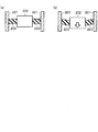
- FIG. 15A is a conceptual diagram of a variable dynamic damper using a magnetic viscoelastic elastomer.
- Reference numeral 201 denotes a housing of the apparatus, and the movable mass 202 is elastically connected to the housing 201 via a magnetic viscoelastic elastomer 203.
- the magnetic viscoelastic elastomer 203 is likely to be irreversibly extended due to deterioration over time (FIG. 15B).
- the movable mass 202 becomes relatively heavy and the spring constant of the magneto-viscoelastic elastomer 203 that holds the movable mass 202 must be set low.
- the spring constant of the magneto-viscoelastic elastomer 203 that holds the movable mass 202 must be set low.
- the movable mass 202 is difficult to hold by reducing the spring constant of the magnetic viscoelastic elastomer 203.
- the movable mass 202 hangs down due to its own weight, causing abnormal noise due to interference or the like.
- the temperature of the magnetic viscoelastic elastomer 203 rises due to the heat generation of the exciting coil and the environment of the place where it is used, which further deteriorates the spring characteristics of the rubber that forms the base of the magnetic viscoelastic elastomer 203, resulting in durability problems. To do. In addition, there is a problem that it is difficult to manage the component characteristics due to characteristic variations when mass-producing the magneto-viscoelastic elastomer 203.
- an object of the present invention is to provide an active vibration control device capable of solving problems such as the magnetic viscoelastic elastomer is likely to deteriorate due to gravity applied to the movable mass and to be elongated.
- the present invention provides a housing, a movable part including at least a movable mass, an excitation coil that generates a magnetic field having a strength corresponding to a supplied current, and a magnitude of the magnetic field generated by the excitation coil.
- a magnetic viscoelastic elastomer whose viscoelastic properties change; and a nonmagnetic support member, wherein the housing and the movable part are elastically coupled by both the magnetic viscoelastic elastomer and the support member.
- This is an active noise vibration control device. According to the present invention, it is possible to solve problems such as that the magnetic viscoelastic elastomer is likely to be deteriorated with age due to gravity applied to the movable mass.
- the support member is set to have a wider width in a direction in which the support member is elastically connected to both the magnetic viscoelastic elastomer and the support member than the magnetic viscoelastic elastomer. May be. According to the present invention, the movable mass can be reliably supported.
- the support member may be sandwiched between the magnetic viscoelastic elastomers.
- the support member and the magnetic viscoelastic elastomer can be handled as an integral member.
- a magnetic path that is a path of the magnetic field generated by the excitation coil is provided as a plurality of magnetic members, and the movable portion includes at least one of the plurality of magnetic members.
- the magnetic viscoelastic elastomer may be arranged so as to constitute the closed magnetic path by connecting a magnetic member constituting the movable part and another magnetic member. According to the present invention, the magnetic flux can be effectively passed through the magneto-viscoelastic elastomer.
- an active vibration control device capable of solving problems such as the magnetic viscoelastic elastomer being easily deteriorated over time due to gravity applied to the movable mass.
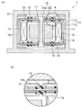
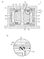
- FIG. 1 is a longitudinal sectional view of an active vibration control device according to a first embodiment of the present invention. It is explanatory drawing explaining passage of the magnetic flux in the active type vibration control apparatus of FIG. 1 is a conceptual diagram of an active vibration control device according to a first embodiment of the present invention. It is a top view which shows the structural example of the magneto-viscoelastic elastomer concerning 1st Embodiment of this invention. It is a top view which shows the structural example of the supporting member of the active type vibration control apparatus concerning 1st Embodiment of this invention. It is a schematic block diagram of the control system of the active vibration control apparatus concerning 1st Embodiment of this invention.
- FIG. 8 is a longitudinal sectional view (a) illustrating a flow of magnetic flux of the active vibration control device in FIG. 7 and a partially enlarged view (b) thereof. It is a longitudinal cross-sectional view of the active vibration control apparatus concerning 3rd Embodiment of this invention. It is a figure explaining the flow of the magnetic flux of the active type vibration control apparatus in FIG. 9 with a broken line arrow. It is a longitudinal cross-sectional view of the active type vibration control apparatus of the modification of the active type vibration control apparatus in FIG. 9, FIG. It is a longitudinal cross-sectional view of the active vibration control apparatus concerning 4th Embodiment of this invention.
- FIG. 1 It is a longitudinal cross-sectional view of the active vibration control apparatus concerning 5th Embodiment of this invention.
- the active vibration control apparatus it is a figure explaining the method of providing a magnetic viscoelastic elastomer, (a), (b) is explaining it with time.
- BRIEF DESCRIPTION OF THE DRAWINGS It is a figure explaining the subject of this invention, Comprising: (a) is a conceptual diagram of an active type vibration control apparatus, (b) is a concept which shows the state which the magneto-viscoelastic elastomer extended in the active type vibration control apparatus.
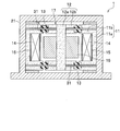
- FIG. 1 is a longitudinal sectional view of an active vibration control device 1 according to a first embodiment of the present invention.
- the active vibration control apparatus 1 includes a non-magnetic cylindrical housing 21.
- a movable portion 17 that is movable by an external input and the first magnetic core 11 are accommodated.
- the movable part 17 includes a second magnetic core 12 and a movable mass 16.
- the housing 21 houses an exciting coil 14 that generates a magnetic field having a strength corresponding to the supplied current.
- the exciting coil 14 is wound around an annular bobbin 15.
- the first magnetic core 11 and the second magnetic core 12 are a plurality of magnetic members in this example, each of which forms a magnetic path that is a path of a magnetic field generated by the exciting coil 14 as an annular closed magnetic path.
- the 2nd magnetic body core 12 comprises the movable part 17, and is provided with the cylinder part 12a extended in the axial direction of the cylinder part 11a, and the 2nd extension part 12b extended toward the circumferential direction outer side from the cylinder part 12a. ing.
- the 1st magnetic body core 11 is provided with the cylindrical part 11a arrange
- the magneto-viscoelastic elastomer 13 is arranged so as to form a closed magnetic circuit by connecting at least one place (upper and lower two places in this example) between the first magnetic core 11 and the second magnetic core 12. ing. That is, the magnetic viscoelastic elastomer 13 connects the first magnetic core 11 and the second magnetic core 12 in a direction perpendicular to the movable direction of the movable portion 17 (horizontal direction in FIG. 1).
- the magnetic viscoelastic elastomer 13 is provided in an annular shape so as to connect the inner end portion of the first extension portion 11b and the outer end portion of the second extension portion 12b.
- the magnetic viscoelastic elastomer 13 is a member whose viscoelastic properties change according to the magnitude of the magnetic field generated by the exciting coil 14.
- the magnetic viscoelastic elastomer 13 is made of an elastic material such as a rubber material to which magnetic particles such as iron powder are added, and has a low rigidity when there is no magnetic field (or a low magnetic field) by the exciting coil 14. In the state where the magnetic field generated by the excitation coil 14 is high, the rigidity is increased.
- a movable mass 16 serving as a non-magnetic mass member constituting the movable portion 17 is provided on the outer periphery of the cylindrical portion 12a.
- FIG. 3 is a conceptual diagram of the active vibration control device 1.
- the movable mass 16 is indirectly supported by the housing 21 by the support member 31 and the magnetic viscoelastic elastomer 13.
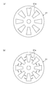
- FIG. 4 is a plan view showing a configuration example of the magnetic viscoelastic elastomer 13. All are circular, and in the example of FIG. 4A, the magnetic powder 13a in the magnetic viscoelastic elastomer 13 is dispersed. In the example of FIG. 4B, the magnetic powder 13a in the magnetic viscoelastic elastomer 13 is arranged toward the center of the ring. In any example, the apparent rigidity can be changed by the intensity of the magnetic flux in the radial direction. However, the example of FIG. 4B can efficiently change the rigidity of the magneto-viscoelastic elastomer 13 with respect to the strength of the magnetic flux.
- FIG. 6 is a schematic configuration diagram of the control system 40 of the active vibration control device 1.
- the table 41 is used to obtain a drive current value corresponding to the rotational speed of the rotary machine M1 in the rotary machine M1, for example, a vehicle engine.
- the power driver 42 including a semiconductor switching element or the like applies the drive current to the exciting coil 14.
- the exciting coil 14 is excited with a drive current corresponding to the rotational speed of the rotating machine M1.
- the magnetic field generated by the exciting coil 14 changes according to the rotational speed of the rotary machine M1, and the stiffness of the magnetic viscoelastic elastomer 13 of the movable portion 17 (mass M) changes, whereby the spring constant of the magnetic viscoelastic elastomer 13 is changed. (K) changes.
- the active vibration control device 1 applies a shearing force to the magnetic viscoelastic elastomer 13 in the vertical direction of FIG. Are out of line. If a magnetic field is applied by the exciting coil 14 at this time, the magnetic powder 13a tends to line up in the direction of the magnetic field. This becomes resistance to external force, and the rigidity of the apparent magneto-viscoelastic elastomer 13 is increased.
- the movable mass 202 becomes relatively heavy and the spring constant of the magneto-viscoelastic elastomer 203 that holds the movable mass 202 must be set low. It can also solve problems when it is not necessary. That is, first, in order to set the natural frequency low, it is possible to prevent the movable mass 202 from being easily held by reducing the spring constant of the magnetic viscoelastic elastomer 203. Further, it is possible to prevent the movable mass 202 from hanging down due to its own weight and causing abnormal noise due to interference or the like.
- the support member 31 is set to have a wider width in the direction connected to the housing 21 side than the magnetic viscoelastic elastomer 13, the movable mass 16 can be reliably supported.
- the support member 31 is vertically sandwiched between the magnetic viscoelastic elastomer 13, the support member 31 and the magnetic viscoelastic elastomer 13 can be handled as an integral member.
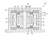
- FIG. 7 is a longitudinal sectional view of an active vibration control device 51 according to the second embodiment of the present invention.
- FIG. 8 is a longitudinal sectional view (a) illustrating the flow of magnetic flux of the active vibration control device 51 and a partially enlarged view (b) thereof.
- the active vibration control device 51 is different from the active vibration control device 1 in that the support member 31 is not sandwiched between the magneto-viscoelastic elastomers 13. That is, in the example of FIGS. 7 and 8, the support member 31 is disposed on the upper magnetic viscoelastic elastomer 13 and the support member 31 is disposed below the lower magnetic viscoelastic elastomer 13.
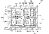
- FIG. 9 is a longitudinal sectional view of an active vibration control apparatus 101 according to the third embodiment of the present invention.
- FIG. 10 is a diagram for explaining the flow of magnetic flux in the active vibration control apparatus 101 with broken-line arrows.
- the same reference numerals are used for members and the like that are common to the first embodiment, and detailed description thereof is omitted.
- This embodiment differs most from the first embodiment in that the excitation coil 14 is provided in two upper and lower stages of the excitation coil 14a and the excitation coil 14b, and as shown in FIG. 10, the excitation coil 14a and the excitation coil 14b. The point is that the direction of the magnetic flux indicated by the broken-line arrow is opposite.
- the active vibration control device 101 has three stages, upper, middle, and lower, in which the first extending portion 11b and the second extending portion 12b are two steps in the upper and lower directions. And the movable mass 16 is also two steps above and below the movable mass 16a and the movable mass 16b.
- the first extending portion 11b side and the second extending portion 12b side in the upper stage are connected by a leaf spring 111 made of a magnetic material.
- the middle first extending portion 11b side and the second extending portion 12b side are connected by a support member 31 and a magnetic viscoelastic elastomer 13 sandwiching the support member 31 from above and below.
- the lower first extension portion 11b side and the second extension portion 12b side are connected by a magnetic plate spring 111.
- FIG. 11 is a modification of the active vibration control device 101 of FIGS. 9 and 10.
- the active vibration control apparatus 101a of this modification is different from the active vibration control apparatus 101 in the following points.
- the first extending portion 11b side and the second extending portion 12b side in the upper stage are connected by a support member 31 and a magnetic viscoelastic elastomer 13 that sandwiches the support member 31 from above and below.
- the middle first extension portion 11b side and the second extension portion 12b side are connected by a leaf spring 111 of magnetic material.
- the lower first extension portion 11b side and the second extension portion 12b side are connected by a support member 31 and a magnetic viscoelastic elastomer 13 sandwiching the support member 31 from above and below.
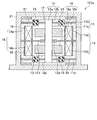
- FIG. 12 is a longitudinal sectional view of an active vibration control device 121 according to the fourth embodiment of the present invention.
- the same reference numerals are used for members and the like that are common to the third embodiment, and detailed description thereof is omitted.
- the active vibration control device 121 is different from the active vibration control device 101 according to the third embodiment.
- the excitation coil 14a and the excitation coil 14b are arranged in the central portion of the active vibration control device 121, that is, in the cylindrical portion 12a. This is a point provided on the outer periphery.
- the movable mass 16a and the movable mass 16b are different in that they are provided on the outer peripheral side of the active vibration control device 121, that is, on the inner peripheral portion of the cylindrical portion 11a. Further, through holes 21a and 21b are formed at the upper and lower portions of the cylindrical portion 12a in the housing 21 in the axial direction, and the upper and lower ends of the cylindrical portion 12a extend out of the housing 21 from the through holes 21a and 21b, respectively. Yes. Linear bushings 122 are provided in the through holes 21a and 21b.
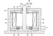
- FIG. 13 is a longitudinal sectional view of an active vibration control device 151 according to the fifth embodiment of the present invention.
- the same reference numerals are used for members and the like that are common to the first embodiment, and detailed description thereof is omitted.
- This active vibration control device 151 is an example used as a vibration isolation device.
- a through hole 21c is formed on the axial direction of the cylindrical portion 12a in the housing 21, and the tip of the cylindrical portion 12a extends from the through hole 21a to the outside of the housing 21. Further, the movable mass 16 is not provided, and the second magnetic core 12 becomes a movable mass.
- Reference numeral 152 denotes a linear bush. The tip of the cylindrical portion 12a extending to the outside of the housing 21 is connected to a vibration isolation target member (not shown) to achieve vibration isolation.
- the first means is a method of separately manufacturing the magnetic viscoelastic elastomer 13 and bonding it to the support member 31. In this case, it is important that the first magnetic core 11 and the second magnetic core 12 are brought into contact with the magnetic viscoelastic elastomer 13. This is because if the space is vacant, the magnetic flux does not efficiently pass through the magneto-viscoelastic elastomer 13.
- the second means constructs a manufacturing jig 171 as shown in FIG. 14 (a), generates a magnetic field by passing a current through the exciting coil 14, and the magnetic viscoelastic elastomer 13 in a state where the magnetic field is generated.
- a method of manufacturing the magnetic viscoelastic elastomer 13 arranged in the radial direction by molding that is, a method of integrally molding the first magnetic core 11 and the second magnetic core 12 (FIG. 14B).
Landscapes
- Engineering & Computer Science (AREA)
- General Engineering & Computer Science (AREA)
- Mechanical Engineering (AREA)
- Physics & Mathematics (AREA)
- Chemical & Material Sciences (AREA)
- Combustion & Propulsion (AREA)
- Acoustics & Sound (AREA)
- Aviation & Aerospace Engineering (AREA)
- Transportation (AREA)
- Electromagnetism (AREA)
- Vibration Prevention Devices (AREA)
- Apparatuses For Generation Of Mechanical Vibrations (AREA)
Abstract
Description

そこで、固有周波数を可変とするダイナミックダンパを実現するために、バネとして磁気粘弾性エラストマ(MRE)を用いた装置が提案されている(特許文献1参照)。これは、磁性体を混入させたゴムに対して印加する磁場の強さを制御することでゴムの剛性を可変とする可変ダイナミックダンパ技術である。
この場合に次のような課題がある。すなわち、可動マス202には常に重力がかかっているため、磁気粘弾性エラストマ203が経年劣化して不可逆的に伸びてしまいやすいという不具合である(図15(b))。
本発明によれば、可動マスにかかる重力により磁気粘弾性エラストマが経年劣化して伸びてしまいやすい等の不具合を解決することができる。
本発明によれば、確実に可動マスを支持することができる。
本発明によれば、支持部材と磁気粘弾性エラストマとを一体の部材として取り扱うことができる。
本発明によれば、磁束を磁気粘弾性エラストマに効果的に通過させることができる。
本発明によれば、磁束を磁気粘弾性エラストマに効果的に通過させることができる。
図1は、本発明の第1実施形態にかかる能動型振動制御装置1の縦断面図である。
能動型振動制御装装置1は、非磁性体の円筒状のハウジング21を備えている。ハウジング21内には、外部からの入力により可動する可動部17と、第1磁性体コア11とが収納されている。可動部17は、第2磁性体コア12と可動マス16とを備えている。また、ハウジング21内には、供給される電流に応じた強さの磁場を発生させる励磁コイル14が収納されている。励磁コイル14は、円環状のボビン15に巻線されている。
第2磁性体コア12は、可動部17を構成し、円柱部11aの軸方向に延びる円柱部12aと、円柱部12aから周方向外側に向けて延出する第2延出部12bとを備えている。
第1磁性体コア11は、ハウジング21と励磁コイル14との間に配置される円筒部11aと、円筒部11aから周方向内側に向けて延出する第1延出部11bとを備えている。
そして、本例では、励磁コイル14が励磁することにより、図2(a)に破線矢印で示すように、円筒部11a、上側の第1延出部11b、上側の第2延出部12b、円柱部12a、下側の第2延出部12b、下側の第1延出部11bを順次通過して、円筒部11aに戻る閉磁路を構成する。
円柱部12aの外周には可動部17を構成する非磁性体の質量部材となる可動マス16が設けられている。
このような支持部材31が上下から磁気粘弾性エラストマ13に挟まれていることは、図2(b)に拡大して図示している。
図4は、磁気粘弾性エラストマ13の構成例を示す平面図である。何れも円環状であり、図4(a)の例は、磁気粘弾性エラストマ13中の磁性体粉13aを分散させている。図4(b)の例は、磁気粘弾性エラストマ13中の磁性体粉13aを円環の中央に向けて配列させている。何れの例でも放射方向の磁束の強さで見かけの剛性を変化させることが出来る。しかし、図4(b)の例の方が、磁束の強さに対し磁気粘弾性エラストマ13の剛性を効率的に変化させることが出来る。
能動型振動制御装置1は、振動の発生により、磁気粘弾性エラストマ13が図1の上下方向に振動すると、磁気粘弾性エラストマ13には図1の上下方向にせん断力がかかり、磁性体粉13aの並びがずれる。このときに励磁コイル14で磁界をかけると、磁性体粉13aが磁場の方向に並ぼうとする。これが、外力に対しての抵抗になり、見掛け上の磁気粘弾性エラストマ13の剛性が高まる。この磁気粘弾性エラストマ13の剛性の変動により、可動部17の共振周波数が変わり、振動を減衰させられる周波数が変わることになる。この場合の剛性の変動は、テーブル41により車両のエンジン等の回転速度に応じて変動するので、車両におけるエンジン等の回転速度の変動に応じて、効果的に振動を抑制することができる。
そして、前記のように支持部材31を設けたことにより、可動マス202には常に重力がかかっていることで、磁気粘弾性エラストマ203が経年劣化して伸びてしまうことを防止することができる。
その上、支持部材31を磁気粘弾性エラストマ13で上下に挟む場合は、支持部材31と磁気粘弾性エラストマ13とを一体の部材として取り扱うことができる。
図7は、本発明の第2実施形態にかかる能動型振動制御装置51の縦断面図である。図8は、同能動型振動制御装置51の磁束の流れを図示した縦断面図(a)、及びその部分拡大図(b)である。本実施形態において第1実施形態と共通する部材等については同一の符号を用い、詳細な説明は省略する。能動型振動制御装置51が前記の能動型振動制御装置1と異なるのは、支持部材31が磁気粘弾性エラストマ13で挟まれていない点にある。
すなわち、図7、図8の例では、上側の磁気粘弾性エラストマ13の上に支持部材31が配置され、下側の磁気粘弾性エラストマ13の下に支持部材31が配置されている。
図9は、本発明の第3実施形態にかかる能動型振動制御装置101の縦断面図である。図10は、同能動型振動制御装置101の磁束の流れを破線矢印で説明する図である。本実施形態において第1実施形態と共通する部材等については同一の符号を用い、詳細な説明は省略する。
本実施形態が第1実施形態と最も異なるのは、励磁コイル14が励磁コイル14aと励磁コイル14bとの上下2段に設けられていて、図10に示すように、励磁コイル14aと励磁コイル14bとでは破線矢印で示す磁束の方向が逆である点である。
これに伴い能動型振動制御装置101は、第1実施形態では第1延出部11b、及び第2延出部12bが上下2段だったのが、上中下の3段になっている。そして、可動マス16も、可動マス16aと可動マス16bの上下2段となっている。
この構成の場合、励磁コイル14aと励磁コイル14bとでは磁束の方向が逆であるため、両励磁コイルから発する磁束は磁気粘弾性エラストマ13では同じ方向に通過するので、磁束が効率的に磁気粘弾性エラストマ13内を通過することができる。
図12は、本発明の第4実施形態にかかる能動型振動制御装置121の縦断面図である。本実施形態において第3実施形態と共通する部材等については同一の符号を用い、詳細な説明は省略する。能動型振動制御装置121が第3実施形態にかかる能動型振動制御装置101と異なるのは、まず、励磁コイル14a及び励磁コイル14bが能動型振動制御装置121の中心部、すなわち、円柱部12aの外周部に設けられている点である。逆に可動マス16a及び可動マス16bは能動型振動制御装置121の外周側、すなわち、円筒部11aの内周部分に設けられている点も異なる。
また、ハウジング21における円柱部12aの軸方向の上下には貫通孔21a,21bが形成されていて、円柱部12aの上下の先は、それぞれ貫通孔21a,21bからハウジング21の外部に延び出ている。貫通孔21a,21bにはリニアブッシュ122が設けられている。
図13は、本発明の第5実施形態にかかる能動型振動制御装置151の縦断面図である。本実施形態において第1実施形態と共通する部材等については同一の符号を用い、詳細な説明は省略する。この能動型振動制御装置151は、防振装置として使用する例である。
次に、前記各能動型振動制御装置において、磁気粘弾性エラストマ13を設ける手段について複数例説明する。
第1の手段は、磁気粘弾性エラストマ13を個別に製造しておき、支持部材31に接着するという方法である。この場合は第1磁性体コア11及び第2磁性体コア12と磁気粘弾性エラストマ13とを接触させることが重要である。空間が空いてしまうと磁束が磁気粘弾性エラストマ13を効率的に通過しないためである。
13 磁気粘弾性エラストマ
14,14a,14b 励磁コイル
17 可動部
21 ハウジング
31 支持部材
11 第1磁性体コア(磁性部材)
12 第2磁性体コア(磁性部材)
111 板バネ(磁性部材)
Claims (5)
- ハウジングと、
少なくとも可動マスを含む可動部と、
供給される電流に応じた強さの磁場を発生させる励磁コイルと、
前記励磁コイルが発生する磁場の大きさに応じて粘弾性的性質が変化する磁気粘弾性エラストマと、
非磁性体の支持部材とを備え、
前記ハウジングと前記可動部とは前記磁気粘弾性エラストマと前記支持部材との両方で弾性的に連結されていることを特徴とする能動型振動制御装置。 - 前記支持部材は、前記磁気粘弾性エラストマよりも前記連結されている方向の幅が広く設定されていることを特徴とする請求項1に記載の能動型振動制御装置。
- 前記支持部材は、前記磁気粘弾性エラストマに挟まれていることを特徴とする請求項1に記載の能動型振動制御装置。
- 前記励磁コイルが発生させる磁場の通り道である磁路を環状の閉磁路として構成する複数の磁性部材を備え、
前記可動部は、
前記複数の磁性部材のうちの少なくとも1つを含んで構成され、
前記磁気粘弾性エラストマは、
前記可動部を構成する磁性部材と他の磁性部材とを連結して前記閉磁路を構成するように配置されることを特徴とする請求項1に記載の能動型振動制御装置。 - 前記励磁コイルは、上下2段に設けられ、
その2段の励磁コイルの間に磁気粘弾性エラストマが形成され、
前記2段の各段の励磁コイルは逆方向の磁場を発生させて前記磁気粘弾性エラストマでは各励磁コイルからの磁束の方向が同じとなることを特徴とする請求項1に記載の能動型振動制御装置。
Priority Applications (5)
| Application Number | Priority Date | Filing Date | Title |
|---|---|---|---|
| US16/301,992 US10731725B2 (en) | 2016-05-17 | 2017-05-10 | Active vibration control device |
| BR112018073620-1A BR112018073620B1 (pt) | 2016-05-17 | 2017-05-10 | Dispositivo de controle de vibração ativa |
| CN201780030434.8A CN109154355B (zh) | 2016-05-17 | 2017-05-10 | 能动型振动控制装置 |
| DE112017002544.3T DE112017002544B4 (de) | 2016-05-17 | 2017-05-10 | Aktive Vibrations-Regel-/Steuervorrichtung |
| JP2018518236A JP6608050B2 (ja) | 2016-05-17 | 2017-05-10 | 能動型振動制御装置 |
Applications Claiming Priority (2)
| Application Number | Priority Date | Filing Date | Title |
|---|---|---|---|
| JP2016098389 | 2016-05-17 | ||
| JP2016-098389 | 2016-05-17 |
Publications (1)
| Publication Number | Publication Date |
|---|---|
| WO2017199801A1 true WO2017199801A1 (ja) | 2017-11-23 |
Family
ID=60325864
Family Applications (1)
| Application Number | Title | Priority Date | Filing Date |
|---|---|---|---|
| PCT/JP2017/017633 Ceased WO2017199801A1 (ja) | 2016-05-17 | 2017-05-10 | 能動型振動制御装置 |
Country Status (7)
| Country | Link |
|---|---|
| US (1) | US10731725B2 (ja) |
| JP (1) | JP6608050B2 (ja) |
| CN (1) | CN109154355B (ja) |
| BR (1) | BR112018073620B1 (ja) |
| DE (1) | DE112017002544B4 (ja) |
| MY (1) | MY180469A (ja) |
| WO (1) | WO2017199801A1 (ja) |
Cited By (3)
| Publication number | Priority date | Publication date | Assignee | Title |
|---|---|---|---|---|
| US10336174B1 (en) | 2018-10-04 | 2019-07-02 | Honda Motor Co., Ltd. | Systems and methods for magnetic engine mount |
| JP2021032265A (ja) * | 2019-08-19 | 2021-03-01 | 公立大学法人 富山県立大学 | 能動型振動制御装置 |
| WO2026048685A1 (ja) * | 2024-08-27 | 2026-03-05 | 株式会社タイカ | 防振ユニット |
Families Citing this family (9)
| Publication number | Priority date | Publication date | Assignee | Title |
|---|---|---|---|---|
| BR112019000157B1 (pt) * | 2016-07-05 | 2021-09-21 | National University Corporation Kanazawa University | Aparelho de controle de vibração de ruído ativo e método para fabricar o mesmo |
| JP6576412B2 (ja) * | 2017-11-17 | 2019-09-18 | 本田技研工業株式会社 | サブフレーム用のマウント |
| JP2020133699A (ja) * | 2019-02-15 | 2020-08-31 | 本田技研工業株式会社 | ダンパーマウント |
| WO2021106094A1 (ja) * | 2019-11-27 | 2021-06-03 | 株式会社東芝 | 支持装置および支持ユニット |
| CN112696451B (zh) * | 2020-01-09 | 2022-09-06 | 北京京西重工有限公司 | 旋转阻尼器组件 |
| JP7116437B2 (ja) * | 2020-12-22 | 2022-08-10 | 本田技研工業株式会社 | サスペンションアームブッシュ |
| EP4402393A1 (en) * | 2021-09-15 | 2024-07-24 | BAE SYSTEMS plc | Resonator, resonator array, vibration control system and method |
| CN115370696B (zh) * | 2022-08-22 | 2024-05-28 | 武汉理工大学 | 基于磁流变弹性体的振动控制tmd装置、方法及系统 |
| CN115111317B (zh) * | 2022-08-29 | 2022-11-11 | 万向钱潮股份公司 | 磁力适应性动力吸振器 |
Citations (5)
| Publication number | Priority date | Publication date | Assignee | Title |
|---|---|---|---|---|
| JP2001234972A (ja) * | 2000-02-24 | 2001-08-31 | Mitsubishi Heavy Ind Ltd | 制振ユニット及び制振装置 |
| DE10302468B3 (de) * | 2003-01-23 | 2004-06-03 | Wegu Gummi- Und Kunststoffwerke Gmbh & Co. Kg | Schwingungstilger mit einstellbarer Tilgereigenfrequenz |
| US20130127098A1 (en) * | 2011-11-23 | 2013-05-23 | Iucf-Hyu (Industry-University Cooperation Foundation Hanyang University) | Variable differential mount apparatus using magnetorheological elastomer |
| JP2016044717A (ja) * | 2014-08-21 | 2016-04-04 | 本田技研工業株式会社 | ダイナミックダンパ制御装置及びトルクロッド |
| WO2016148011A1 (ja) * | 2015-03-16 | 2016-09-22 | 本田技研工業株式会社 | ダイナミックダンパ、防振装置、及び磁気粘弾性エラストマの製造方法 |
Family Cites Families (10)
| Publication number | Priority date | Publication date | Assignee | Title |
|---|---|---|---|---|
| JP2002106633A (ja) * | 2000-09-28 | 2002-04-10 | Tokai Rubber Ind Ltd | 防振用アクチュエータおよびそれを用いた能動型防振装置 |
| CN102654170A (zh) | 2006-12-06 | 2012-09-05 | 翔风技术有限公司 | 减振装置及减振装置的偏移校正方法 |
| CN101324257B (zh) * | 2008-07-11 | 2010-04-07 | 重庆大学 | 基于磁流变弹性元件与阻尼元件耦合作用的可控隔振器 |
| JPWO2012026332A1 (ja) | 2010-08-25 | 2013-10-28 | パナソニック株式会社 | 磁気応答型弾性装置 |
| CN201982575U (zh) | 2011-04-19 | 2011-09-21 | 宁波大学 | 一种可变刚度的隔振器 |
| CN202510617U (zh) | 2012-04-20 | 2012-10-31 | 谢宁 | 一种摇动式磁流变阻尼器 |
| CN103727167B (zh) | 2014-01-23 | 2015-11-18 | 重庆大学 | 一种用于微振动控制的智能隔振器 |
| CN104747651B (zh) * | 2015-01-28 | 2016-07-20 | 合肥工业大学 | 一种并联模式半主动隔振器 |
| JP6294364B2 (ja) * | 2016-01-29 | 2018-03-14 | 本田技研工業株式会社 | 固有値可変型動吸振器及び固有値可変型防振装置 |
| JP6405336B2 (ja) * | 2016-05-11 | 2018-10-17 | 本田技研工業株式会社 | 能動型振動制御装置 |
-
2017
- 2017-05-10 JP JP2018518236A patent/JP6608050B2/ja not_active Expired - Fee Related
- 2017-05-10 WO PCT/JP2017/017633 patent/WO2017199801A1/ja not_active Ceased
- 2017-05-10 MY MYPI2018001987A patent/MY180469A/en unknown
- 2017-05-10 US US16/301,992 patent/US10731725B2/en active Active
- 2017-05-10 CN CN201780030434.8A patent/CN109154355B/zh active Active
- 2017-05-10 DE DE112017002544.3T patent/DE112017002544B4/de active Active
- 2017-05-10 BR BR112018073620-1A patent/BR112018073620B1/pt not_active IP Right Cessation
Patent Citations (5)
| Publication number | Priority date | Publication date | Assignee | Title |
|---|---|---|---|---|
| JP2001234972A (ja) * | 2000-02-24 | 2001-08-31 | Mitsubishi Heavy Ind Ltd | 制振ユニット及び制振装置 |
| DE10302468B3 (de) * | 2003-01-23 | 2004-06-03 | Wegu Gummi- Und Kunststoffwerke Gmbh & Co. Kg | Schwingungstilger mit einstellbarer Tilgereigenfrequenz |
| US20130127098A1 (en) * | 2011-11-23 | 2013-05-23 | Iucf-Hyu (Industry-University Cooperation Foundation Hanyang University) | Variable differential mount apparatus using magnetorheological elastomer |
| JP2016044717A (ja) * | 2014-08-21 | 2016-04-04 | 本田技研工業株式会社 | ダイナミックダンパ制御装置及びトルクロッド |
| WO2016148011A1 (ja) * | 2015-03-16 | 2016-09-22 | 本田技研工業株式会社 | ダイナミックダンパ、防振装置、及び磁気粘弾性エラストマの製造方法 |
Cited By (4)
| Publication number | Priority date | Publication date | Assignee | Title |
|---|---|---|---|---|
| US10336174B1 (en) | 2018-10-04 | 2019-07-02 | Honda Motor Co., Ltd. | Systems and methods for magnetic engine mount |
| JP2021032265A (ja) * | 2019-08-19 | 2021-03-01 | 公立大学法人 富山県立大学 | 能動型振動制御装置 |
| JP7101410B2 (ja) | 2019-08-19 | 2022-07-15 | 公立大学法人 富山県立大学 | 能動型振動制御装置 |
| WO2026048685A1 (ja) * | 2024-08-27 | 2026-03-05 | 株式会社タイカ | 防振ユニット |
Also Published As
| Publication number | Publication date |
|---|---|
| DE112017002544T5 (de) | 2019-02-21 |
| JPWO2017199801A1 (ja) | 2019-03-14 |
| CN109154355B (zh) | 2021-04-02 |
| US20190154108A1 (en) | 2019-05-23 |
| US10731725B2 (en) | 2020-08-04 |
| BR112018073620A2 (pt) | 2019-02-26 |
| BR112018073620B1 (pt) | 2023-05-02 |
| CN109154355A (zh) | 2019-01-04 |
| DE112017002544B4 (de) | 2020-10-01 |
| MY180469A (en) | 2020-11-30 |
| JP6608050B2 (ja) | 2019-11-20 |
Similar Documents
| Publication | Publication Date | Title |
|---|---|---|
| JP6608050B2 (ja) | 能動型振動制御装置 | |
| US10267373B2 (en) | Characteristic value variable dynamic vibration absorber and characteristic value variable vibration isolator | |
| JP6329693B2 (ja) | ダイナミックダンパ、防振装置、及び磁気粘弾性エラストマの製造方法 | |
| JP6301397B2 (ja) | トーションダンパ | |
| US10399122B2 (en) | Vibration motor | |
| JP6405336B2 (ja) | 能動型振動制御装置 | |
| JP6058527B2 (ja) | トルクロッドの振動低減装置 | |
| JP5770442B2 (ja) | 車両用電動式アクティブ動吸振装置 | |
| CN107448538A (zh) | 电磁式致动器和使用其的能动型减振器及其制造方法 | |
| CN107368114B (zh) | 主动型振动控制装置 | |
| JP2020060208A (ja) | マウントブッシュ | |
| US8387959B2 (en) | Structure of orifice plate for engine mount filled with magnetorheological fluid | |
| JP6644632B2 (ja) | 電磁式アクチュエータおよび能動型制振装置と能動型防振装置 | |
| JP6369901B2 (ja) | ダイナミックダンパ制御装置 | |
| US20110148236A1 (en) | Temperature compensation tunable magnetic damping | |
| JP2019039530A (ja) | 緩衝装置 | |
| JP2005344810A (ja) | 磁気ダンパ装置 | |
| JP2000035083A (ja) | 能動的防振用加振器 | |
| Genta et al. | From oil to magnetic fields: active and passive vibration control | |
| JP2006234113A (ja) | 防振装置 |
Legal Events
| Date | Code | Title | Description |
|---|---|---|---|
| ENP | Entry into the national phase |
Ref document number: 2018518236 Country of ref document: JP Kind code of ref document: A |
|
| REG | Reference to national code |
Ref country code: BR Ref legal event code: B01A Ref document number: 112018073620 Country of ref document: BR |
|
| 121 | Ep: the epo has been informed by wipo that ep was designated in this application |
Ref document number: 17799226 Country of ref document: EP Kind code of ref document: A1 |
|
| ENP | Entry into the national phase |
Ref document number: 112018073620 Country of ref document: BR Kind code of ref document: A2 Effective date: 20181116 |
|
| 122 | Ep: pct application non-entry in european phase |
Ref document number: 17799226 Country of ref document: EP Kind code of ref document: A1 |