WO2017199889A1 - Dispositif de vision pour véhicules - Google Patents
Dispositif de vision pour véhicules Download PDFInfo
- Publication number
- WO2017199889A1 WO2017199889A1 PCT/JP2017/018096 JP2017018096W WO2017199889A1 WO 2017199889 A1 WO2017199889 A1 WO 2017199889A1 JP 2017018096 W JP2017018096 W JP 2017018096W WO 2017199889 A1 WO2017199889 A1 WO 2017199889A1
- Authority
- WO
- WIPO (PCT)
- Prior art keywords
- rib
- vehicle
- rigid member
- visual recognition
- extending
- Prior art date
- Legal status (The legal status is an assumption and is not a legal conclusion. Google has not performed a legal analysis and makes no representation as to the accuracy of the status listed.)
- Ceased
Links
Images


Classifications
-
- B—PERFORMING OPERATIONS; TRANSPORTING
- B60—VEHICLES IN GENERAL
- B60R—VEHICLES, VEHICLE FITTINGS, OR VEHICLE PARTS, NOT OTHERWISE PROVIDED FOR
- B60R1/00—Optical viewing arrangements; Real-time viewing arrangements for drivers or passengers using optical image capturing systems, e.g. cameras or video systems specially adapted for use in or on vehicles
- B60R1/12—Mirror assemblies combined with other articles, e.g. clocks
-
- B—PERFORMING OPERATIONS; TRANSPORTING
- B60—VEHICLES IN GENERAL
- B60R—VEHICLES, VEHICLE FITTINGS, OR VEHICLE PARTS, NOT OTHERWISE PROVIDED FOR
- B60R1/00—Optical viewing arrangements; Real-time viewing arrangements for drivers or passengers using optical image capturing systems, e.g. cameras or video systems specially adapted for use in or on vehicles
- B60R1/006—Side-view mirrors, e.g. V-shaped mirrors located at the front or rear part of the vehicle
-
- B—PERFORMING OPERATIONS; TRANSPORTING
- B60—VEHICLES IN GENERAL
- B60R—VEHICLES, VEHICLE FITTINGS, OR VEHICLE PARTS, NOT OTHERWISE PROVIDED FOR
- B60R1/00—Optical viewing arrangements; Real-time viewing arrangements for drivers or passengers using optical image capturing systems, e.g. cameras or video systems specially adapted for use in or on vehicles
- B60R1/02—Rear-view mirror arrangements
- B60R1/06—Rear-view mirror arrangements mounted on vehicle exterior
-
- B—PERFORMING OPERATIONS; TRANSPORTING
- B60—VEHICLES IN GENERAL
- B60R—VEHICLES, VEHICLE FITTINGS, OR VEHICLE PARTS, NOT OTHERWISE PROVIDED FOR
- B60R1/00—Optical viewing arrangements; Real-time viewing arrangements for drivers or passengers using optical image capturing systems, e.g. cameras or video systems specially adapted for use in or on vehicles
- B60R1/20—Real-time viewing arrangements for drivers or passengers using optical image capturing systems, e.g. cameras or video systems specially adapted for use in or on vehicles
- B60R1/22—Real-time viewing arrangements for drivers or passengers using optical image capturing systems, e.g. cameras or video systems specially adapted for use in or on vehicles for viewing an area outside the vehicle, e.g. the exterior of the vehicle
- B60R1/23—Real-time viewing arrangements for drivers or passengers using optical image capturing systems, e.g. cameras or video systems specially adapted for use in or on vehicles for viewing an area outside the vehicle, e.g. the exterior of the vehicle with a predetermined field of view
- B60R1/26—Real-time viewing arrangements for drivers or passengers using optical image capturing systems, e.g. cameras or video systems specially adapted for use in or on vehicles for viewing an area outside the vehicle, e.g. the exterior of the vehicle with a predetermined field of view to the rear of the vehicle
-
- B—PERFORMING OPERATIONS; TRANSPORTING
- B60—VEHICLES IN GENERAL
- B60R—VEHICLES, VEHICLE FITTINGS, OR VEHICLE PARTS, NOT OTHERWISE PROVIDED FOR
- B60R11/00—Arrangements for holding or mounting articles, not otherwise provided for
- B60R11/04—Mounting of cameras operative during drive; Arrangement of controls thereof relative to the vehicle
-
- B—PERFORMING OPERATIONS; TRANSPORTING
- B60—VEHICLES IN GENERAL
- B60R—VEHICLES, VEHICLE FITTINGS, OR VEHICLE PARTS, NOT OTHERWISE PROVIDED FOR
- B60R1/00—Optical viewing arrangements; Real-time viewing arrangements for drivers or passengers using optical image capturing systems, e.g. cameras or video systems specially adapted for use in or on vehicles
- B60R1/12—Mirror assemblies combined with other articles, e.g. clocks
- B60R2001/1253—Mirror assemblies combined with other articles, e.g. clocks with cameras, video cameras or video screens
-
- B—PERFORMING OPERATIONS; TRANSPORTING
- B60—VEHICLES IN GENERAL
- B60R—VEHICLES, VEHICLE FITTINGS, OR VEHICLE PARTS, NOT OTHERWISE PROVIDED FOR
- B60R11/00—Arrangements for holding or mounting articles, not otherwise provided for
- B60R2011/0001—Arrangements for holding or mounting articles, not otherwise provided for characterised by position
- B60R2011/004—Arrangements for holding or mounting articles, not otherwise provided for characterised by position outside the vehicle
-
- B—PERFORMING OPERATIONS; TRANSPORTING
- B60—VEHICLES IN GENERAL
- B60R—VEHICLES, VEHICLE FITTINGS, OR VEHICLE PARTS, NOT OTHERWISE PROVIDED FOR
- B60R11/00—Arrangements for holding or mounting articles, not otherwise provided for
- B60R2011/0042—Arrangements for holding or mounting articles, not otherwise provided for characterised by mounting means
- B60R2011/0043—Arrangements for holding or mounting articles, not otherwise provided for characterised by mounting means for integrated articles, i.e. not substantially protruding from the surrounding parts
- B60R2011/0045—Arrangements for holding or mounting articles, not otherwise provided for characterised by mounting means for integrated articles, i.e. not substantially protruding from the surrounding parts with visible part, e.g. flush mounted
-
- B—PERFORMING OPERATIONS; TRANSPORTING
- B60—VEHICLES IN GENERAL
- B60R—VEHICLES, VEHICLE FITTINGS, OR VEHICLE PARTS, NOT OTHERWISE PROVIDED FOR
- B60R2300/00—Details of viewing arrangements using cameras and displays, specially adapted for use in a vehicle
- B60R2300/10—Details of viewing arrangements using cameras and displays, specially adapted for use in a vehicle characterised by the type of camera system used
-
- B—PERFORMING OPERATIONS; TRANSPORTING
- B60—VEHICLES IN GENERAL
- B60R—VEHICLES, VEHICLE FITTINGS, OR VEHICLE PARTS, NOT OTHERWISE PROVIDED FOR
- B60R2300/00—Details of viewing arrangements using cameras and displays, specially adapted for use in a vehicle
- B60R2300/80—Details of viewing arrangements using cameras and displays, specially adapted for use in a vehicle characterised by the intended use of the viewing arrangement
- B60R2300/8046—Details of viewing arrangements using cameras and displays, specially adapted for use in a vehicle characterised by the intended use of the viewing arrangement for replacing a rear-view mirror system
Definitions
- the present invention relates to a vehicular visual recognition device that assists occupants' visual recognition.
- the bracket member is extended from the vehicle body side, the camera is supported by the bracket member, and the cover member covers the bracket member and the camera.
- the rigidity can be improved.
- This invention is made in view of the said fact, and aims at providing the visual recognition apparatus for vehicles which can improve rigidity.
- the extending member is extended from the vehicle body side, the covering member covers the extending member, and the visual recognition unit is supported by at least one of the extending member and the covering member.
- the covering member is provided with a first rib, and the first rib is extended in the extending direction of the extending member.
- the extending member and the first rib can be brought into contact with each other.
- the rigidity of the visual recognition device for vehicles can be improved because one of the extending member and the covering member is reinforced by the other.
- a vehicle visual recognition device is the vehicle visual recognition device according to the first aspect, wherein the first rib protrudes toward the extending member, and a protruding tip contacts the extending member. Has been made possible.
- the first rib protrudes toward the extending member and can contact the extending member. Thereby, one of the extending member and the covering member can reinforce the other.
- a vehicle visual recognition device is the vehicle visual recognition device according to the first or second aspect, wherein at least one of the vehicle body side and the vehicle body side opposite to the vehicle body side in the extending direction of the extending member. And a protrusion that is provided so as to be able to come into contact with an end of the first rib in the extending direction.
- the extending member is provided with a protrusion, and the protrusion and the end of the first rib in the extending direction can be brought into contact with each other. Thereby, one of the extending member and the covering member can reinforce the other.
- the vehicle visual recognition device is the vehicle visual recognition device according to any one of the first to third aspects, in which the first rib protrudes in the vertical direction.
- the first rib protrudes in the vertical direction.
- either the extending member or the covering member can reinforce the other in the vertical direction.
- a vehicle visual recognition device is the vehicle visual recognition device according to any one of the first to fourth aspects.
- the vehicle visual recognition device is provided on the extending member and is capable of contacting the first rib.
- a second rib is included.
- the extending member is provided with the second rib so that the second rib and the first rib can come into contact with each other. Thereby, one of the extending member and the covering member can reinforce the other.
- a vehicle visual recognition device is the vehicle visual recognition device according to the fifth aspect, wherein the first rib and the second rib are disposed between one of the plurality of the first rib and the second rib. Is provided.
- one of the first rib and the second rib is provided in plural, and the other of the first rib and the second rib is one of the first rib and the second rib. It is provided in between. Thereby, one of the extending member and the covering member can reinforce the other.
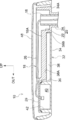
- FIG. 1 is a perspective view of an imaging device 10 as a vehicle visual recognition device according to the present embodiment as viewed obliquely from the upper front of the vehicle
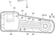
- FIG. 2 illustrates the imaging device 10 as viewed from above. It is shown in a plan view. 3 is a cross-sectional view of the imaging device 10 as viewed from the front of the vehicle.
- the central portion of the imaging device 10 in the vehicle width direction is viewed from the outside in the vehicle width direction (right side). It is shown in a sectional view. Note that.
- the front side of the vehicle is indicated by an arrow FR
- the outer side in the vehicle width direction (right side of the vehicle) is indicated by an arrow OUT
- the upper side is indicated by an arrow UP.
- the imaging device 10 is installed outside the vehicle front side end of the middle portion in the vertical direction of a side door (front side door) 14 as the vehicle body side of the vehicle 12.
- the side door 14 is provided with a cylindrical support cylinder 16 (see FIGS. 2 and 3) as a vehicle attachment member.
- the support cylinder 16 extends upward, and the axial direction is parallel to the vertical direction. Is arranged.
- the imaging device 10 is provided with a long and substantially plate-like rigid member 18 as a stretching member, and the rigid member 18 is made of metal or resin.
- the rigid member 18 extends from the side door 14 to the outside in the vehicle width direction.
- a mounting portion 20 is integrally provided at the inner end of the rigid member 18 in the vehicle width direction.
- the mounting portion 20 is provided with a cylindrical body portion 22 and a rotating shaft 24 as protrusions, and the cylindrical body portion 22 and the rotating shaft 24 are formed into a bottomed cylindrical shape and a cylindrical shape, respectively.
- the rotary shaft 24 has a smaller diameter than the cylindrical body portion 22 and is disposed coaxially with the cylindrical body portion 22.
- the rotary shaft 24 extends downward from the bottom wall (lower wall) of the cylindrical body portion 22. It has been extended.
- a support cylinder 16 of a stay (not shown) assembled to the side door 14 is fitted into the rotary shaft 24, and an upper end portion of the rotary shaft 24 is inserted into the cylindrical body portion 22. .
- the rigid member 18 is supported by the side door 14 so as to be rotatable in the vehicle front-rear direction around the support cylinder 16. Further, the rotation of the rigid member 18 in the vehicle front-rear direction is limited, and when a load in the vehicle front-rear direction greater than a predetermined load is input to the rigid member 18, the rigid member 18 moves in the vehicle front-rear direction. Rotation is allowed.
- the rigid member 18 is formed with a long rectangular flat base 18A on the outer side in the vehicle width direction of the mounting portion 20, and the base 18A extends outward in the vehicle width direction.
- a standing wall 26 is erected at an end portion in the vehicle front-rear direction, and each inner end in the vehicle width direction of the standing wall 26 is connected to the peripheral wall of the cylindrical body portion 22. The space between the standing walls 26 is in communication with the cylindrical body portion 22.
- a substantially rectangular parallelepiped box-shaped covering lid 28 is provided at the outer end of the rigid member 18 in the vehicle width direction.
- the covering lid 28 is open to the lower side and the standing wall 26 is connected to the peripheral wall. Has been.
- a plurality of second ribs 30 as second ribs are integrally provided on the lower surface of the base portion 18A.
- two second ribs 30 are provided, and the second ribs 30 are arranged at a predetermined interval in the vehicle front-rear direction.
- Each of the second ribs 30 protrudes downward from the lower surface of the base portion 18 ⁇ / b> A and extends outward from the peripheral wall of the cylindrical body portion 22 in the vehicle width direction, and the extending tip reaches the vicinity of the covering lid 28.
- the rigidity of the rigid member 18 is increased by providing the second rib 30.
- a long, substantially rectangular parallelepiped box-shaped design housing 32 that is a part of the covering member.
- the design housing 32 is attached to the rigid member 18. In comparison, the rigidity is low.
- the interior of the design housing 32 is open to the upper side, and the rigid member 18 is accommodated in the design housing 32.
- a fitting hole 34 ⁇ / b> A is formed through the bottom wall 34 at the bottom of the design housing 32 at the inner end in the vehicle width direction.
- the lower end portion of the cylindrical portion 22 of the rigid member 18 is fitted into the fitting hole 34 ⁇ / b> A, whereby the support cylinder 16 of the side door 14 and the rotating shaft 24 of the rigid member 18 are connected to the design housing 32. It extends downward from the lower side of the inner end in the vehicle width direction.
- the design housing 32 is fastened and fixed to the rigid member 18, and the design housing 32 is reinforced by the rigid member 18.
- the design housing 32 covers the rigid member 18 and configures the outer periphery of the imaging device 10 (the outer periphery of the vehicle 12).
- the design housing 32 configures the design surface of the imaging device 10.
- a U-shaped covering peripheral wall 36 is provided in the vehicle width direction outer side end portion of the design casing 32, and the entire lower end of the covering peripheral wall 36 is integrated with the bottom wall 34 of the design casing 32. ing.
- the vehicle front side portion of the covering peripheral wall 36 is disposed on the vehicle rear side of the vehicle front side wall of the design housing 32, and the entire vehicle rear side end of the covering peripheral wall 36 in the vehicle width direction inner side portion and the vehicle width direction outer side portion is
- the design housing 32 is integrated with the vehicle rear side wall.
- a first rib 38 as a first rib is integrally provided on the bottom wall 34 of the design housing 32.
- the first ribs 38 are disposed between the second ribs 30 of the rigid member 18, and the first ribs 38 protrude upward from the bottom wall 34. Further, the first rib 38 extends from the inner side in the vehicle width direction of the covering peripheral wall 36 to the inner side in the vehicle width direction.
- the bottom wall 34 of the design housing 32 is highly rigid because the first rib 38 is integrally formed.
- the protruding tip 38A of the first rib 38 is disposed in the immediate vicinity of the base 18A of the rigid member 18, and the distance between the protruding tip 38A and the base 18A is the same as the protruding tip (lower end) of the second rib 30 of the rigid member 18.
- the distance between the design housing 32 and the bottom wall 34 is smaller.
- the extending tip 38 ⁇ / b> B on the inner side in the vehicle width direction of the first rib 38 is disposed in the immediate vicinity of the peripheral wall on the outer side in the vehicle width direction of the cylindrical body portion 22.
- a predetermined gap is provided between the first rib 38 of the design housing 32 and the second rib 30 of the rigid member 18.
- the inside of the covering peripheral wall 36 is a substantially rectangular parallelepiped storage chamber 40.
- a substantially rectangular covering hole 42 is formed on the upper surface of the covering peripheral wall 36 on the front side of the vehicle.
- the covering hole 42 opens the accommodation chamber 40 upward, and the upper side is covered by the covering lid 28 of the rigid member 18. It is covered.
- the accommodation chamber 40 accommodates a camera 44 as a visual recognition unit and an imaging unit, and the camera 44 is fastened and fixed to the design housing 32.
- a control device (not shown) in the vehicle 12 is electrically connected to the camera 44, and the camera 44 is operated by the control device.
- a substantially cylindrical lens portion 46 is provided at the vehicle rear side end portion of the camera 44, and the lens portion 46 passes through the vehicle rear side wall of the accommodation chamber 40.
- the lens unit 46 is exposed to the outside of the design housing 32 in a state of being directed to the rear side of the vehicle, and the camera 44 images the rear side of the vehicle by being actuated.
- a monitor (not shown) as a display unit is electrically connected to the control device, and a video (or image) captured by the camera 44 is displayed on the monitor under the control of the control device.
- the monitor is arranged in the passenger compartment, and the occupant of the vehicle 12 assists the occupant in viewing the rear side of the vehicle by checking the image displayed on the monitor (image captured by the camera 44).
- a long, substantially rectangular parallelepiped box-shaped design cover 48 that is a part of the covering member is provided on the upper side of the periphery of the rigid member 18.
- the design cover 48 includes the rigid member 18 and the design housing. Compared to 32, the rigidity is lowered. The interior of the design cover 48 is open to the lower side, and the design cover 48 is engaged with the entire periphery of the design housing 32 so as to cover the rigid member 18 and the upper surface of the design housing 32. .
- the design cover 48 constitutes the outer periphery of the imaging device 10 (the outer periphery of the vehicle 12), and the design cover 48 constitutes the design surface of the imaging device 10 together with the design housing 32.
- the imaging device 10 having the above configuration extends from the side door 14 to the outside in the vehicle width direction. For this reason, for example, when a person (for example, a child) hangs on the imaging device 10, the design cover 48 is deformed, and a predetermined load or more is input to the rigid member 18 from above, so that the rigid member 18 is moved to the vehicle. There is a possibility of bending downward in the width direction.
- the first wall 38 is provided on the bottom wall 34 of the design housing 32, and the protruding tip 38 ⁇ / b> A of the first rib 38 is disposed below the base 18 ⁇ / b> A of the rigid member 18. For this reason, the base 18 ⁇ / b> A of the rigid member 18 abuts on the protruding tip 38 ⁇ / b> A of the first rib 38. Thereby, the rigidity with respect to the load from the upper side of the imaging device 10 can be improved because the rigid member 18 is reinforced by the design housing 32. Further, since the first rib 38 is extended in the vehicle width direction, the design housing 32 is reinforced by the first rib 38, and the rigidity against the load from the upper side of the imaging device 10 can be improved.
- the extending tip 38B on the inner side in the vehicle width direction of the first rib 38 is disposed in the vicinity of the peripheral wall of the cylindrical portion 22 of the rigid member 18.
- the rigid member 18 is bent downward in the vehicle width direction by the load from the upper side, so that the cylindrical body portion 22 comes into contact with the extending tip 38 ⁇ / b> B of the first rib 38.
- the rigidity with respect to the load from the upper side of the imaging device 10 can be improved because the rigid member 18 is reinforced by the design housing 32.
- the imaging device 10 collides from the front side or the rear side of the vehicle during traveling of the vehicle, there is a possibility that a predetermined or higher impact load is input to the design housing 32 from the front side or the rear side of the vehicle.
- the second rib 30 is provided in the rigid member 18, and the second rib 30 is disposed in the immediate vicinity of the first rib 38 on the vehicle front side and the vehicle rear side.
- the second rib 30 is extended in the vehicle width direction, and the rigid member 18 is reinforced by the second rib 30.
- casing 32 is reinforced by the 2nd rib 30, and the rigidity with respect to the load from the upper side of the imaging device 10 can be improved further.
- the movement of the design housing 32 in the vehicle front-rear direction relative to the rigid member 18 can be limited by inserting the first rib 38 between the second ribs 30. . Thereby, the assembly of the design housing 32 to the rigid member 18 can be facilitated.
- the extending tip 38B of the first rib 38 is disposed in the immediate vicinity of the peripheral wall of the cylindrical portion 22 of the rigid member 18, the movement of the design housing 32 relative to the rigid member 18 in the vehicle width direction can be restricted, and the rigid member Assembling of the design housing 32 to 18 can be further facilitated.
- the first rib 38 is provided so that the extending tip 38B on the inner side in the vehicle width direction of the first rib 38 is located in the immediate vicinity of the peripheral wall of the cylindrical portion 22 of the rigid member 18. Instead, it is only necessary that at least one of the ends of the first rib 38 in the extending direction is opposed to the protrusion of the rigid member 18 and reaches the vicinity of the protrusion.
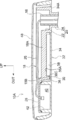
- FIG. 5 shows a cross-sectional view of the imaging apparatus 10A according to the modification as viewed from the front side of the vehicle.
- the rigid member 18 is provided with a protruding portion 18 ⁇ / b> B as a protruding portion on the inner side in the vehicle width direction than the covering lid 28.
- the protruding portion 18B protrudes downward from the base portion 18A so as to connect the pair of second ribs 30 of the rigid member 18.
- the extending tip 38C on the outer side in the vehicle width direction of the first rib 38 of the design housing 32 is disposed in the immediate vicinity of the protruding portion 18B.
- the rigid member 18 bends downward in the vehicle width direction due to the load from above, so that the protruding tip 38A and the extended tip 38C of the first rib 38 are brought into contact with the base 18A and the protruding portion 18B of the rigid member 18, respectively. Touch. Therefore, the rigidity against the load from the upper side of the imaging device 10A can be improved.
- the second rib 30 is provided on the rigid member 18 so as to sandwich the first rib 38.
- one second rib 30 may be provided on the rigid member 18, and two first ribs 38 may be provided on the design housing 32 so as to sandwich the second rib 30.
- the rigid member 18 can be brought into contact with the protruding tip 38A of the first rib 38 and the extended tip 38B or the extended tip 38C, only the protruding tip 38A or at least one of the extended tip 38B and the extended tip 38C is rigid member 18. It may be possible to come into contact with.
- the first rib 38 is provided in the design housing 32, but the first rib may be provided in the design cover 48.
- the design housing 32 may be provided with the first rib 38 and the design cover 48 may be provided with the first rib.
- the imaging device 10 is installed on the side door 14 of the vehicle 12.
- the imaging device 10 is not limited to this and is installed in a part other than the side door 14 of the vehicle 12. May be.
- the protruding tip 38A, the extending tip 38B, and the extending tip 38C of the first rib 38 are positioned in the immediate vicinity of the base portion 18A of the rigid member 18, the immediate vicinity of the peripheral wall of the cylindrical portion 22, and the protruding portion. It arrange
- the protruding tip 38A, the extending tip 38B, and the extending tip 38C of the first rib 38 may be in contact with the base portion 18A of the rigid member 18, the peripheral wall of the cylindrical portion 22, and the protruding portion 18B.
- the imaging devices 10 and 10A provided with the camera 44 as the visual recognition unit have been described as an example.
- the imaging device as the vehicle visual recognition device is waterproofed as the visual recognition unit.
- the camera 44 or a waterproof camera may be attached to the rigid member 18 as the extending member.
- the imaging devices 10 and 10A provided with the camera 44 as the visual recognition unit have been described as an example.
- the vehicle visual device is replaced with the camera 44 or the camera 44.
- a mirror device provided with a mirror may also be used.
Landscapes
- Engineering & Computer Science (AREA)
- Multimedia (AREA)
- Mechanical Engineering (AREA)
- Fittings On The Vehicle Exterior For Carrying Loads, And Devices For Holding Or Mounting Articles (AREA)
- Rear-View Mirror Devices That Are Mounted On The Exterior Of The Vehicle (AREA)
Abstract
La présente invention concerne un dispositif de capture d'image (10) qui est pourvu d'un élément rigide (18) qui s'étend vers l'extérieur dans la direction de la largeur du véhicule et d'un boîtier de conception (32) qui recouvre l'élément rigide (18). Le boîtier de conception (32) est pourvu d'une première nervure (38) faisant saillie vers la base (18A) de l'élément rigide (18), et l'extrémité avant saillante (38A) de la première nervure (38) peut venir en contact avec l'élément rigide (18). Lorsque l'extrémité avant saillante (38A) de la première nervure (38) vient en contact avec l'élément rigide (18), l'élément rigide (18) est renforcé par le boîtier de conception (32) pour augmenter la rigidité vis-à-vis de la charge du dispositif de capture d'image (10).
Priority Applications (1)
| Application Number | Priority Date | Filing Date | Title |
|---|---|---|---|
| US16/099,318 US20190135184A1 (en) | 2016-05-20 | 2017-05-12 | Vehicle visual recognition device |
Applications Claiming Priority (2)
| Application Number | Priority Date | Filing Date | Title |
|---|---|---|---|
| JP2016101849A JP2017206204A (ja) | 2016-05-20 | 2016-05-20 | 車両用視認装置 |
| JP2016-101849 | 2016-05-20 |
Publications (1)
| Publication Number | Publication Date |
|---|---|
| WO2017199889A1 true WO2017199889A1 (fr) | 2017-11-23 |
Family
ID=60325933
Family Applications (1)
| Application Number | Title | Priority Date | Filing Date |
|---|---|---|---|
| PCT/JP2017/018096 Ceased WO2017199889A1 (fr) | 2016-05-20 | 2017-05-12 | Dispositif de vision pour véhicules |
Country Status (3)
| Country | Link |
|---|---|
| US (1) | US20190135184A1 (fr) |
| JP (1) | JP2017206204A (fr) |
| WO (1) | WO2017199889A1 (fr) |
Families Citing this family (2)
| Publication number | Priority date | Publication date | Assignee | Title |
|---|---|---|---|---|
| JP6724077B2 (ja) * | 2018-08-02 | 2020-07-15 | 本田技研工業株式会社 | 自動車のドア構造 |
| JP7334381B2 (ja) * | 2019-03-22 | 2023-08-29 | 株式会社東海理化電機製作所 | 車両用カメラ装置 |
Citations (3)
| Publication number | Priority date | Publication date | Assignee | Title |
|---|---|---|---|---|
| JPS6238738U (fr) * | 1985-08-29 | 1987-03-07 | ||
| JPS6264651U (fr) * | 1985-10-14 | 1987-04-22 | ||
| JPH09507810A (ja) * | 1994-11-02 | 1997-08-12 | ユナイテッド テクノロジーズ オートモーティブ システムズ,インコーポレイテッド | 外側サイド取付後方ミラーの旋回軸マウント |
-
2016
- 2016-05-20 JP JP2016101849A patent/JP2017206204A/ja active Pending
-
2017
- 2017-05-12 WO PCT/JP2017/018096 patent/WO2017199889A1/fr not_active Ceased
- 2017-05-12 US US16/099,318 patent/US20190135184A1/en not_active Abandoned
Patent Citations (3)
| Publication number | Priority date | Publication date | Assignee | Title |
|---|---|---|---|---|
| JPS6238738U (fr) * | 1985-08-29 | 1987-03-07 | ||
| JPS6264651U (fr) * | 1985-10-14 | 1987-04-22 | ||
| JPH09507810A (ja) * | 1994-11-02 | 1997-08-12 | ユナイテッド テクノロジーズ オートモーティブ システムズ,インコーポレイテッド | 外側サイド取付後方ミラーの旋回軸マウント |
Also Published As
| Publication number | Publication date |
|---|---|
| JP2017206204A (ja) | 2017-11-24 |
| US20190135184A1 (en) | 2019-05-09 |
Similar Documents
| Publication | Publication Date | Title |
|---|---|---|
| JP6683474B2 (ja) | 撮像装置 | |
| KR102123496B1 (ko) | 센서 탑재 구조 | |
| JP2014033448A (ja) | 車両用のミラー代替システム | |
| JP2016215685A (ja) | 車載機器用カバー構造 | |
| WO2018047744A1 (fr) | Dispositif visuel pour véhicule | |
| WO2017199889A1 (fr) | Dispositif de vision pour véhicules | |
| JP7103601B2 (ja) | カメラ装置 | |
| US20160159284A1 (en) | Vehicle visual recognition device | |
| JP4309883B2 (ja) | 自動車の側方領域のための監視装置 | |
| JP2019182361A (ja) | 車両用視認装置 | |
| JP6180836B2 (ja) | エアバッグ装置 | |
| JP2017035928A (ja) | 車両用撮像装置、車両用周辺視認装置 | |
| JP6767186B2 (ja) | 車載用カメラ装置 | |
| JP6268085B2 (ja) | 撮像装置 | |
| CN107009857A (zh) | 后尾门 | |
| JP2016168925A (ja) | 撮像装置 | |
| JP6248992B2 (ja) | 電線ガイド装置 | |
| US10277784B2 (en) | Camera imaging device for a vehicle | |
| JP2014170623A (ja) | 電気的素子のシール構造 | |
| JP7372822B2 (ja) | 車両用サイドミラー | |
| JP6692120B2 (ja) | 車両用視認装置 | |
| JP7218716B2 (ja) | 車載カメラカバー | |
| JP2020063015A (ja) | 車両用視認装置 | |
| JP6310761B2 (ja) | 車両用ドアミラー | |
| JP6955882B2 (ja) | グロメット及びワイヤーハーネス |
Legal Events
| Date | Code | Title | Description |
|---|---|---|---|
| NENP | Non-entry into the national phase |
Ref country code: DE |
|
| 121 | Ep: the epo has been informed by wipo that ep was designated in this application |
Ref document number: 17799313 Country of ref document: EP Kind code of ref document: A1 |
|
| 122 | Ep: pct application non-entry in european phase |
Ref document number: 17799313 Country of ref document: EP Kind code of ref document: A1 |