WO2017199911A1 - 回転切削工具を用いたディンプル加工方法 - Google Patents
回転切削工具を用いたディンプル加工方法 Download PDFInfo
- Publication number
- WO2017199911A1 WO2017199911A1 PCT/JP2017/018204 JP2017018204W WO2017199911A1 WO 2017199911 A1 WO2017199911 A1 WO 2017199911A1 JP 2017018204 W JP2017018204 W JP 2017018204W WO 2017199911 A1 WO2017199911 A1 WO 2017199911A1
- Authority
- WO
- WIPO (PCT)
- Prior art keywords
- dimple
- cutting tool
- rotary cutting
- dimples
- workpiece
- Prior art date
- Legal status (The legal status is an assumption and is not a legal conclusion. Google has not performed a legal analysis and makes no representation as to the accuracy of the status listed.)
- Ceased
Links
Images


Classifications
-
- B—PERFORMING OPERATIONS; TRANSPORTING
- B23—MACHINE TOOLS; METAL-WORKING NOT OTHERWISE PROVIDED FOR
- B23C—MILLING
- B23C3/00—Milling particular work; Special milling operations; Machines therefor
- B23C3/28—Grooving workpieces
- B23C3/34—Milling grooves of other forms, e.g. circumferential
-
- B—PERFORMING OPERATIONS; TRANSPORTING
- B23—MACHINE TOOLS; METAL-WORKING NOT OTHERWISE PROVIDED FOR
- B23C—MILLING
- B23C3/00—Milling particular work; Special milling operations; Machines therefor
-
- B—PERFORMING OPERATIONS; TRANSPORTING
- B23—MACHINE TOOLS; METAL-WORKING NOT OTHERWISE PROVIDED FOR
- B23C—MILLING
- B23C3/00—Milling particular work; Special milling operations; Machines therefor
- B23C3/02—Milling surfaces of revolution
-
- B—PERFORMING OPERATIONS; TRANSPORTING
- B23—MACHINE TOOLS; METAL-WORKING NOT OTHERWISE PROVIDED FOR
- B23C—MILLING
- B23C5/00—Milling-cutters
- B23C5/02—Milling-cutters characterised by the shape of the cutter
- B23C5/10—Shank-type cutters, i.e. with an integral shaft
-
- B—PERFORMING OPERATIONS; TRANSPORTING
- B23—MACHINE TOOLS; METAL-WORKING NOT OTHERWISE PROVIDED FOR
- B23C—MILLING
- B23C5/00—Milling-cutters
- B23C5/02—Milling-cutters characterised by the shape of the cutter
- B23C5/12—Cutters specially designed for producing particular profiles
-
- B—PERFORMING OPERATIONS; TRANSPORTING
- B23—MACHINE TOOLS; METAL-WORKING NOT OTHERWISE PROVIDED FOR
- B23C—MILLING
- B23C5/00—Milling-cutters
- B23C5/02—Milling-cutters characterised by the shape of the cutter
- B23C5/12—Cutters specially designed for producing particular profiles
- B23C5/14—Cutters specially designed for producing particular profiles essentially comprising curves
-
- B—PERFORMING OPERATIONS; TRANSPORTING
- B23—MACHINE TOOLS; METAL-WORKING NOT OTHERWISE PROVIDED FOR
- B23C—MILLING
- B23C2210/00—Details of milling cutters
- B23C2210/04—Angles
- B23C2210/0407—Cutting angles
-
- B—PERFORMING OPERATIONS; TRANSPORTING
- B23—MACHINE TOOLS; METAL-WORKING NOT OTHERWISE PROVIDED FOR
- B23C—MILLING
- B23C2210/00—Details of milling cutters
- B23C2210/20—Number of cutting edges
- B23C2210/201—Number of cutting edges one
-
- B—PERFORMING OPERATIONS; TRANSPORTING
- B23—MACHINE TOOLS; METAL-WORKING NOT OTHERWISE PROVIDED FOR
- B23C—MILLING
- B23C2220/00—Details of milling processes
- B23C2220/04—Milling with the axis of the cutter inclined to the surface being machined
-
- B—PERFORMING OPERATIONS; TRANSPORTING
- B23—MACHINE TOOLS; METAL-WORKING NOT OTHERWISE PROVIDED FOR
- B23C—MILLING
- B23C2220/00—Details of milling processes
- B23C2220/36—Production of grooves
-
- B—PERFORMING OPERATIONS; TRANSPORTING
- B23—MACHINE TOOLS; METAL-WORKING NOT OTHERWISE PROVIDED FOR
- B23C—MILLING
- B23C2220/00—Details of milling processes
- B23C2220/48—Methods of milling not otherwise provided for
-
- B—PERFORMING OPERATIONS; TRANSPORTING
- B23—MACHINE TOOLS; METAL-WORKING NOT OTHERWISE PROVIDED FOR
- B23C—MILLING
- B23C2222/00—Materials of tools or workpieces composed of metals, alloys or metal matrices
- B23C2222/28—Details of hard metal, i.e. cemented carbide
-
- B—PERFORMING OPERATIONS; TRANSPORTING
- B23—MACHINE TOOLS; METAL-WORKING NOT OTHERWISE PROVIDED FOR
- B23C—MILLING
- B23C2222/00—Materials of tools or workpieces composed of metals, alloys or metal matrices
- B23C2222/32—Details of high-speed steel
-
- B—PERFORMING OPERATIONS; TRANSPORTING
- B23—MACHINE TOOLS; METAL-WORKING NOT OTHERWISE PROVIDED FOR
- B23C—MILLING
- B23C2224/00—Materials of tools or workpieces composed of a compound including a metal
- B23C2224/22—Titanium aluminium carbide nitride (TiAlCN)
-
- B—PERFORMING OPERATIONS; TRANSPORTING
- B23—MACHINE TOOLS; METAL-WORKING NOT OTHERWISE PROVIDED FOR
- B23C—MILLING
- B23C2224/00—Materials of tools or workpieces composed of a compound including a metal
- B23C2224/24—Titanium aluminium nitride (TiAlN)
-
- B—PERFORMING OPERATIONS; TRANSPORTING
- B23—MACHINE TOOLS; METAL-WORKING NOT OTHERWISE PROVIDED FOR
- B23C—MILLING
- B23C2226/00—Materials of tools or workpieces not comprising a metal
- B23C2226/31—Diamond
-
- Y—GENERAL TAGGING OF NEW TECHNOLOGICAL DEVELOPMENTS; GENERAL TAGGING OF CROSS-SECTIONAL TECHNOLOGIES SPANNING OVER SEVERAL SECTIONS OF THE IPC; TECHNICAL SUBJECTS COVERED BY FORMER USPC CROSS-REFERENCE ART COLLECTIONS [XRACs] AND DIGESTS
- Y10—TECHNICAL SUBJECTS COVERED BY FORMER USPC
- Y10T—TECHNICAL SUBJECTS COVERED BY FORMER US CLASSIFICATION
- Y10T407/00—Cutters, for shaping
- Y10T407/19—Rotary cutting tool
- Y10T407/1946—Face or end mill
- Y10T407/1948—Face or end mill with cutting edge entirely across end of tool [e.g., router bit, end mill, etc.]
-
- Y—GENERAL TAGGING OF NEW TECHNOLOGICAL DEVELOPMENTS; GENERAL TAGGING OF CROSS-SECTIONAL TECHNOLOGIES SPANNING OVER SEVERAL SECTIONS OF THE IPC; TECHNICAL SUBJECTS COVERED BY FORMER USPC CROSS-REFERENCE ART COLLECTIONS [XRACs] AND DIGESTS
- Y10—TECHNICAL SUBJECTS COVERED BY FORMER USPC
- Y10T—TECHNICAL SUBJECTS COVERED BY FORMER US CLASSIFICATION
- Y10T409/00—Gear cutting, milling, or planing
- Y10T409/30—Milling
- Y10T409/303752—Process
- Y10T409/303808—Process including infeeding
Definitions
- the present invention relates to a dimple processing method for forming dimples which are minute dents on a surface of a workpiece by a rotary cutting tool.
- Dimples which are a number of minute dents, may be formed on the surface of a workpiece such as aluminum, copper alloy, cast products thereof, cast iron, or resin.
- a satin pattern may be formed on the surface of the workpiece by a plurality of dimples. This is because by forming dimples on the workpiece, it is possible to reduce the frictional resistance generated between the counterpart material in contact with the workpiece and the workpiece.
- the principle is that, for example, wear powder is generated by contact between the workpiece and the counterpart material, and the wear powder is sandwiched between the workpiece and the counterpart material to increase the frictional resistance. By containing the wear powder in the dimple, it is possible to suppress an increase in frictional resistance due to the wear powder.
- oil may be injected between the workpiece and the counterpart material, and the dimple may be filled with oil.
- oil is discharged from the dimple between the counterpart material and the workpiece under high pressure (squeeze effect). This pressure makes it difficult for the mating material to contact the workpiece, thereby reducing the frictional resistance between the mating material and the workpiece.
- dimples may be formed on the inner wall of a cylindrical member such as an engine cylinder or turbocharger, or on the joint surface of an artificial joint.
- Known methods for processing dimples include a laser irradiation method, a shot peening method in which microspheres collide with a workpiece at high speed, and the like.
- laser irradiation since the workpiece is heated at a high temperature, there is a problem that a large thermal stress is generated on the workpiece, and that dross (melt) is attached to the workpiece. It is difficult to remove bulges and dross produced by the laser.
- shot peening the periphery of the dimple may swell and the workpiece may not be flat.
- residual stress is generated around the dimples, which may cause deformation or breakage of the workpiece.
- JP-A-10-052998 discloses a method for decorating the surface of a workpiece using a rotary cutting tool such as a milling cutter or an end mill.
- a rotary cutting tool such as a milling cutter or an end mill.
- the cutting edge of the rotary cutting tool is slightly applied to the surface of the workpiece while rotating the rotary cutting tool.
- a polka dot pattern having a plurality of circles can be formed on the surface of the workpiece.
- the circles are formed, for example, in parallel in the axial direction of the rotary cutting tool, and are also formed at equal intervals in the feed direction orthogonal to the axial direction.
- One feature of the present invention relates to a dimple processing method for forming dimples on a workpiece using a rotary cutting tool.
- a rotary cutting tool having a cutting edge protruding in the axial direction from a position shifted from the axial center at the tip of a rod-shaped main body is prepared.
- the rotary cutting tool is set so that the axis of the rotary cutting tool is inclined with respect to the vertical line of the processed surface of the workpiece.
- the rotary cutting tool and the workpiece are relatively fed so that the rotary cutting tool moves along the processing surface while rotating the rotary cutting tool around the axis.
- the rotary cutting tool is rod-shaped and has a cutting edge protruding in the axial direction at the tip. Therefore, the cutting edge can be rotated with a smaller diameter than the cutting edge protruding in the radial direction. As a result, a small dimple can be formed by the cutting edge.
- the cutting edge protrudes from a position shifted from the axis of the tip of the main body. Therefore, when the rotary cutting tool is tilted and rotated with respect to the processing surface, the cutting edge cuts the processing surface or leaves the processing surface. Thereby, a plurality of dimples spaced apart from each other can be easily formed.
- FIG. 6 is a cross-sectional view of a workpiece and a counterpart material facing the workpiece along the VI-VI line in FIG. 5. It is a schematic diagram which shows the moving direction of the other party material which faces a workpiece. It is a schematic diagram which shows the moving direction of the other party material which faces a workpiece.
- FIG. 1 It is a partially expanded front view of the front-end
- FIG. 34 is a partially enlarged top view of a workpiece including dimples formed using the rotary cutting tool of FIG. 33. It is a partially enlarged top view of a workpiece including a plurality of types of dimples. It is a partially expanded top view of a workpiece having dimples positioned in another pattern. It is a partially expanded top view of a workpiece having dimples positioned in another pattern. It is a partially expanded top view of a workpiece having dimples positioned in another pattern. It is a partially expanded top view of a workpiece having dimples positioned in another pattern. It is a partially expanded top view of a workpiece having dimples positioned in another pattern. It is a partially expanded top view of a workpiece having dimples positioned in another pattern. It is a partially expanded top view of a workpiece having dimples positioned in another pattern. It is a partially expanded top view of a workpiece having dimples positioned in another pattern. It is a partially expanded top view of a work
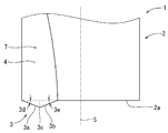
- a rotary cutting tool 1 shown in FIG. 1 is a rotary cutting tool for forming a plurality of spaced dimples (small dents) 22.
- the rotary cutting tool 1 has a rod-like main body 2 and a cutting edge (bottom edge) 3 protruding from the tip 2 a of the main body 2.
- the main body 2 has a round bar shape or a cylindrical shape, and has a diameter of 2 to 10 mm, for example, 4 mm.
- the main body 2 has a tip (bottom surface) 2 a that is substantially orthogonal to the axis 5.
- the shaft center 5 is located at the center of the cross section of the main body 2 and extends in the longitudinal direction.
- the cutting edge 3 is located at a position away from the axis 5 of the main body 2 and protrudes in the axial direction from the tip 2 a of the main body 2.
- the cutting edge 3 is formed continuously with a groove (flute) 7 formed in the main body 2, and protrudes in the axial direction from the tip of the groove 7.
- the cutting edge 3 has a substantially triangular shape, and has a first bottom blade 3a positioned radially outward and a second bottom blade 3b positioned radially inward.
- the first bottom blade 3 a extends obliquely in a straight line from the outer peripheral edge of the tip 2 a of the main body 2 or near the outer peripheral edge toward the axis 5.
- the first bottom blade 3 a has a first angle 3 d in the axial direction with respect to a plane orthogonal to the axis 5.
- the second bottom blade 3b is located between the first bottom blade 3a and the shaft center 5, and extends linearly from the substantially radial center of the main body 2 toward the outer peripheral edge.
- the second bottom blade 3 b has a second angle 3 e in the axial direction with respect to a plane orthogonal to the axis 5.
- the first angle 3d and the second angle 3e are acute angles, for example, 1 to 30 °, specifically 15 °.
- the first bottom blade 3a and the second bottom blade 3b are connected with an angle at the bottom blade tip 3c.
- the cutting edge 3 has a rake face 4 on a face continuous with the bottom of the groove 7.
- the cutting edge 3 has a flank 8 on the opposite side of the rake face 4.
- the flank 8 has a first flank 8a extending from the first bottom blade 3a and a second flank 8b extending from the second bottom blade 3b.
- the first flank 8 a extends obliquely from the first bottom blade 3 a toward the tip 2 a of the main body 2.
- the second flank 8b is substantially triangular and extends obliquely from the second bottom blade 3b toward the tip 2a of the main body 2.
- the first flank 8a has a first angle 3f with respect to the ridgeline of the first flank 8a and the second flank 8b.
- the second flank 8b has a second angle 3g with respect to the ridgeline.
- the first angle 3f and the second angle 3g are such that when the rotary cutting tool 1 is sent to the workpiece 20, the cutting surface of the workpiece 20 does not interfere with the first flank 8a and the second flank 8b.
- the first angle 3 f and the second angle 3 g are set to a size of 20 ⁇ 10 ° when the first flank 8 a and the second flank 8 b are projected onto a plane orthogonal to the axis 5.
- the cutting edge 3 is formed from the same material as the main body 2 of the rotary cutting tool 1 or from a different material.
- the cutting edge 3 and the main body 2 are formed from tool steel, high-speed steel (high-speed tool steel), or cemented carbide.
- the main body 2 is formed from carbon steel, stainless steel, tool steel, high speed steel, cemented carbide, and the cutting edge 3 is formed from polycrystalline diamond (PCD), cubic boron nitride (CBN), ceramics, and cut.
- PCD polycrystalline diamond
- CBN cubic boron nitride
- the blade 3 is joined to the main body 2.
- the cutting edge 3 is formed of the same or different material as that of the main body 2, and a surface treatment such as coating is applied to a region corresponding to the cutting edge 3.
- the surface treatment is performed, for example, by chemical vapor deposition (CVD) or physical vapor deposition (PVD), and the Ti-based TiAlN, TiAlCrN, TiAlCrSiN, or other coating layers such as CVD diamond and diamond-like carbon (DLC) are cut. Used as blade 3.
- CVD chemical vapor deposition
- PVD physical vapor deposition
- Ti-based TiAlN, TiAlCrN, TiAlCrSiN, or other coating layers such as CVD diamond and diamond-like carbon (DLC) are cut. Used as blade 3.
- the rotary cutting tool 1 is set so that the axis 5 has a predetermined angle 10 with respect to the vertical line of the processing surface 21 of the workpiece 20.
- the rotary cutting tool 1 is set so that the tip of the cutting edge 3 has a predetermined depth 11 with respect to the processing surface 21.
- the rotary cutting tool 1 is rotated around an axis 5 and the cutting edge 3 cuts the machining surface 21 in a predetermined rotation angle region.
- the cutting edge 3 moves away from the machining surface 21 in another rotation angle region. Thereby, the cutting edge 3 cuts the processed surface 21 intermittently.
- the rotary cutting tool 1 makes one revolution, one cutting edge 3 creates one dimple.
- the predetermined angle 10 is 60 ° or less, 45 ° or less, 30 ° or less so that the cutting edge 3 cuts the processed surface 21, and preferably the dimple 22 has a predetermined length 22e as shown in FIG. Set to As shown in FIG. 6, the predetermined depth 11 is set such that the maximum depth of the dimple 22 is, for example, 0.1 to 0.001 mm, specifically 0.01 mm.
- the dimple 22 is very small, and the length 22e in the cutting direction is, for example, 0.5 to 1 mm.
- the cutting direction is a direction in which the cutting edge 3 advances with respect to the machining surface 21. For example, a point at which a predetermined portion of the cutting edge 3 reaches the machining surface 21 and a point away from the machining surface 21. It is the direction that tied.
- the dimple 22 has a width orthogonal to the cutting direction.
- the maximum width 22f which is the maximum width, is shorter than the length 22e, and is, for example, half or less of the length 22e.
- the maximum width 22f is, for example, 0.01 to 0.5 mm.
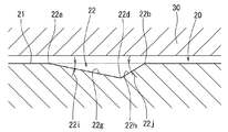
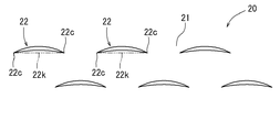
- the dimple 22 has a first side 22a, a second side 22b facing the first side 22a, and both ends 22c connecting the first side 22a and the second side 22b.
- the first side 22a and the second side 22b are curved and are arranged in the width direction.
- the first side 22a and the second side 22b swell in the same direction, in other words, the first side 22a swells in one side in the width direction, and the second side 22b dents in one side in the width direction.
- the dimple 22 has a crescent shape. All or most of the first side 22a and the second side 22b are located in a region on one side of a line 22k connecting both ends 22c.
- the dimple 22 has a first inclined surface 22g extending from the first side 22a and a second inclined surface 22h extending from the second side 22b.
- the first inclined surface 22g has a first depth angle 22i with respect to the processed surface 21, and gradually becomes deeper from the first side 22a toward the second side 22b.
- the second inclined surface 22h has a second depth angle 22j with respect to the processed surface 21, and gradually becomes deeper from the second side 22b toward the first side 22a.
- the second depth angle 22j is larger than the first depth angle 22i.
- the dimple 22 has a groove bottom line 22d connecting the deepest part in the width direction, and the groove bottom line 22d is located closer to the second side 22b than a line connecting the center of the dimple 22 in the width direction.
- friction caused when the workpiece 20 having the dimples 22 and the counterpart material 30 facing the workpiece 20 are relatively moved is reduced by the dimples 22.
- wear powder is generated from one or both of the members, and the wear powder is held in the dimple 22. Most of the wear powder is held near the groove bottom line 22d.
- the workpiece 20 may be moved with respect to the counterpart material 30 in one width direction, specifically, in the direction in which the first side 22 a of the dimple 22 swells.
- the wear powder moves from the first side 22 a toward the second side 22 b with respect to the dimple 22 in the same manner as the counterpart material 30.
- the second inclined surface 22h has a larger inclination angle than the first inclined surface 22g. Therefore, the wear powder is effectively suppressed from being discharged from the dimple 22 by the second inclined surface 22h.
- the workpiece 20 may be moved with respect to the counterpart material 30 in the other side in the width direction, specifically, in the direction opposite to the direction in which the first side 22a of the dimple 22 swells.
- the grease passing through the dimple 22 moves from the second side 22b toward the first side 22a with respect to the dimple 22 in the same manner as the counterpart material 30.
- the inclination angle of the first inclined surface 22g is gentler than that of the second inclined surface 22h. Therefore, the pressure of the grease gradually increases using the first inclined surface 22g. For example, the rate of increase in pressure is smaller than when the pressure increases using the second inclined surface 22h. Therefore, there is little pressure loss and the grease pressure is reliably increased. As a result, the squeeze effect due to the pressure of the grease increases, and the friction between the workpiece 20 and the counterpart material 30 can be efficiently reduced.
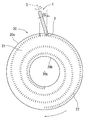
- the workpiece 20 is cylindrical, for example, as shown in FIG. 9, and has an outer peripheral surface 20a and an inner peripheral surface 20b.
- the workpiece 20 has a flat processed surface 21 at one end in the axial direction, and a plurality of dimples 22 are formed on the processed surface 21.
- the plurality of dimples 22 are arranged in the circumferential direction and also in the radial direction of the workpiece 20.
- the plurality of dimples 22 are formed, for example, in a spiral shape on the processing surface 21 and are arranged in parallel in the circumferential direction and the radial direction.
- the processing apparatus 70 includes an X-axis guide 71, an X-direction moving member 72 that can move along the X-axis guide 71, a Y-direction moving member 73 that moves in the Y-axis direction with respect to the X-direction moving member 72, A Z-direction moving member 74 that moves in the Z-axis direction with respect to the direction-moving member 73 is provided.
- the X-axis guide 71 is held by a support base (not shown) and extends in the X-axis direction.
- the X axis direction, the Y axis direction, and the Z axis direction are orthogonal to each other.
- the X direction moving member 72 has, for example, a nut member of a feed screw mechanism.
- the nut member is rotated by a servo motor 96 (see FIG. 11) and moves with respect to a screw shaft provided on the X-axis guide 71.
- the X-direction moving member 72 moves relative to the X-axis guide 71 using a rack and pinion mechanism and a servo motor 96.
- the Y direction moving member 73 and the Z direction moving member 74 are, for example, in the Y direction and the Z direction with respect to the X direction moving member 72 using a feed screw mechanism, a rack and pinion mechanism, and servo motors 97 and 98 (see FIG. 11). Moving.
- the processing apparatus 70 includes a swinging member 75 that is mounted on the Z-direction moving member 74 so as to be capable of adjusting the angle, and a spindle 76 that is provided on the swinging member 75 so as to be rotatable.
- the swing member 75 swings in the X direction or the Y direction with respect to the Z direction moving member 74 using a servo motor 99 (see FIG. 11).
- the rotary cutting tool 1 is mounted on the spindle 76, and the spindle 76 rotates the rotary cutting tool 1 about the axis 5 using the servo motor 100 (see FIG. 11).
- the movement or rotation of each member of the processing apparatus 70 is controlled by a control unit 93 stored in the PC 90 shown in FIG.
- the workpiece 20 is held by the workpiece holding device 80.
- the work holding device 80 includes a base 81 and a table 82 that is rotatably mounted on the upper surface of the base 81.
- the table 82 rotates with respect to the base 81 using a servo motor 101 (see FIG. 11) or the like.
- the workpiece 20 is mounted on the table 82, and the table 82 rotates around the axis 20 c of the workpiece 20 together with the workpiece 20 using the servo motor 101.
- the servo motor 101 is controlled by a control unit 93 stored in the PC 90.
- the movement control and rotation control of each member of the processing device 70 and the work holding device 80 are controlled by the control unit (CPU) 93 in the PC 90 via the I / F circuit 94.
- the ROM 95 stores instructions and data necessary for the execution of the control unit 93.
- Data relating to the machining mode, coordinate data of the workpiece 20, data relating to the rotation speed of the spindle 76, etc. are input via a keyboard or the like and stored in the storage unit (RAM) 92 via the I / F circuit 91.
- the controller 93 transmits a predetermined drive command to each of the motors 96 to 101 based on the stored data, and each of the motors 96 to 101 performs a predetermined drive operation based on the transmission signal.
- the axis 5 of the rotary cutting tool 1 is set at a predetermined angle 10 with respect to the machining surface 21.
- the position in the depth direction (Z direction) is determined in consideration of the cutting depth of the processed surface 21 by the cutting edge 3. While the rotary cutting tool 1 is rotated at a predetermined rotation speed, the workpiece 20 is rotated at a predetermined rotation speed. At the same time, the rotary cutting tool 1 is moved from the outer peripheral surface 20a of the workpiece 20 toward the inner peripheral surface 20b.
- the rotary cutting tool 1 rotates once, the cutting edge 3 cuts the processed surface 21, and one dimple 22 is formed.
- the machining surface 21 rotates with respect to the rotary cutting tool 1, and the machining surface 21 is sent to the rotary cutting tool 1.
- the rotary cutting tool 1 rotates, and the dimple 22 is formed by the cutting edge 3. Thereby, the plurality of dimples 22 are formed in a state of being separated from each other.
- the rotary cutting tool 1 is inclined in the feed direction of the workpiece 20, that is, in the rotation direction of the workpiece 20. Therefore, the dimple 22 is formed so that its longitudinal direction is substantially orthogonal to the feed direction of the workpiece 20.
- the plurality of dimples 22 are juxtaposed in the feed direction and the width direction.
- the rotary cutting tool 1 moves in the radial direction with respect to the processing surface 21, for example, from the outer peripheral surface 20a toward the inner peripheral surface 20b. Therefore, the plurality of dimples 22 are arranged in a spiral shape on the processed surface 21 and arranged in the circumferential direction and the radial direction.
- the rotational speed of the rotary cutting tool 1, the rotational speed of the workpiece 20, and the moving speed of the rotary cutting tool 1 in the radial direction can be adjusted so that the intervals between the plurality of spaced dimples 22 are equal. For example, when the rotary cutting tool 1 is located in the vicinity of the outer peripheral surface 20a of the workpiece 20, the rotary cutting tool 1 is rotated at a high speed. Then, as the rotary cutting tool 1 approaches the inner peripheral surface 20b of the workpiece 20, the rotational speed of the rotary cutting tool 1 is decreased.
- the workpiece 20 is rotated at 17 rpm.
- the rotary cutting tool 1 is moved from the vicinity of the outer peripheral surface 20a of the workpiece 20 toward the inner peripheral surface 20b at a constant speed in the radial direction.
- the rotary cutting tool 1 is moved in the radial direction, and the rotational speed of the rotary cutting tool 1 is gradually reduced from 5100 rpm to 1360 rpm. As a result, the intervals between the plurality of dimples 22 become substantially equal.
- the rotational speed of the rotary cutting tool 1 is made constant, and the rotary cutting tool 1 is moved in the radial direction from the vicinity of the outer peripheral surface 20a toward the inner peripheral surface 20b. Then, the rotational speed of the workpiece 20 can be gradually increased as the rotary cutting tool 1 approaches the inner peripheral surface 20b.
- the intervals between the plurality of dimples 22 can be made substantially equal.
- the small dimples 22 are sequentially formed in the width direction (lateral direction in FIG. 12).
- the plurality of dimples 22 spaced apart from each other are arranged side by side in the width direction on the processing surface 21 of the workpiece 20.
- the dimples 22 are formed so as to be spirally arranged on the processed surface 21, and are arranged in parallel in the radial direction (the vertical direction in FIG. 12) at substantially equal intervals.
- the number and position of the dimples 22 are determined so as to occupy an area of 10-30% of the processed surface 21, for example, about 20%.
- the processed surface 21 on which the dimples 22 are formed faces the counterpart material 30 as shown in FIGS.
- the machining surface 21 is rotated with respect to the counterpart material 30 around the axis 20c (see FIG. 9) of the workpiece 20, for example. Since the dimples 22 are non-circular, the dimples 22 have directivity, and the plurality of dimples 22 face the same direction with respect to the counterpart material 30 that moves relatively.
- the mating member 30 moves from the first side 22 a toward the second side 22 b with respect to the dimple 22.
- the plurality of dimples 22 face the same direction with respect to the counterpart material 30 that rotates relative to the other dimples 22. Therefore, the plurality of dimples 22 have the same effect on the counterpart material 30.
- the mating member 30 may move from the second side 22 b toward the first side 22 a with respect to the dimple 22 as shown in FIG. 8.
- the plurality of dimples 22 are directed in the same direction with respect to the counterpart material 30 that rotates relatively. Therefore, the plurality of dimples 22 have the same effect on the counterpart material 30.
- Dimples 22 are formed on the workpiece 20 as shown in FIG.
- the dimple 22 can reduce the frictional resistance generated between the counterpart material 30 that contacts the workpiece 20 and the workpiece 20.
- wear powder is generated when the workpiece 20 and the mating material 30 come into contact with each other, and the wear powder is sandwiched between the workpiece 20 and the mating material 30 to increase the frictional resistance. There is a case.
- oil is injected between the workpiece 20 and the counterpart material 30, and the dimple 22 is filled with oil. Therefore, oil can be held by the dimples 22 to prevent the workpiece 20 and the counterpart material 30 from contacting each other without oil, or the workpiece 20 and the counterpart material 30 adhere to each other via wear powder. Can be prevented.
- oil is discharged from the dimple 22 between the mating material 30 and the workpiece 20 at a high pressure to form a lubricating film (squeeze effect). This pressure makes it difficult for the mating member 30 to come into contact with the workpiece 20 and reduces the frictional resistance between the mating material 30 and the workpiece 20.
- this embodiment relates to a dimple processing method in which a dimple 22 is formed on a workpiece 20 using a rotary cutting tool 1 as shown in FIG.
- a rotary cutting tool 1 having a cutting edge 3 protruding in the axial direction from a position shifted from the axial center 5 at the tip of a rod-shaped main body 2 is prepared.
- the rotary cutting tool 1 is set so that the axis 5 of the rotary cutting tool 1 is inclined with respect to the vertical line of the processing surface 21 of the workpiece 20.
- the rotary cutting tool 1 and the workpiece 20 are relatively fed so that the rotary cutting tool 1 moves along the machining surface 21 while rotating the rotary cutting tool 1 around the axis 5.
- the machining surface 21 is cut by the cutting edge 3 to form dimples 22 that are spaced apart from each other on the machining surface 21.
- the rotary cutting tool 1 has a cutting edge 3 that is rod-shaped and protrudes in the axial direction at the tip. Therefore, the cutting edge 3 can be rotated with a smaller diameter than the cutting edge protruding in the radial direction. As a result, a small dimple 22 can be formed by the cutting edge 3.
- the cutting edge 3 protrudes from a position shifted from the axis 5 at the tip of the main body 2. Therefore, when the rotary cutting tool 1 is tilted and rotated with respect to the processing surface 21, the cutting edge 3 cuts the processing surface 21 or leaves the processing surface 21. Thus, a plurality of dimples 22 that are separated from each other can be easily formed.
- the cutting edge 3 enters the workpiece 20 obliquely with respect to the processing surface 21 and gradually cuts the processing surface 21 deeply. Then, the cutting edge 3 gradually cuts the machining surface 21 to be shallow, and retreats from the workpiece 20 obliquely. Accordingly, as shown in FIG. 5, the dimple 22 is shallow at both ends 22c and deep at the approximate center in the length direction.
- a dimple formed by irradiating a processed surface with a laser or a dimple formed by shot peening has an abrupt angle that is substantially perpendicular to the processed surface. Compared to such a dimple, the dimple 22 does not have an abrupt angle with respect to the processed surface 21. As a result, the dimple 22 does not have a sudden angle change with respect to the processed surface 21 and easily exhibits a squeeze effect due to grease pressure.
- the cutting edge 3 starts cutting from the cutting start point (for example, one of both ends 22 c of FIG. 5) with respect to the processing surface 21 as the rotary cutting tool 1 rotates, and the cutting end point ( For example, it leaves
- the dimple 22 has a first side 22a and a second side 22b facing each other in a direction orthogonal to a line 22k connecting the cutting start point and the cutting end point.
- the first side 22a is curved so as to swell in one direction with respect to the connected line 22k.
- the second side 22b is curved so as to extend along the connected line 22k or expand in the one direction.
- the dimple 22 is not circular but has a directional shape, for example, a crescent shape. Therefore, as shown in FIG. 6, the moving direction of the counterpart material 30 relative to the dimple 22 can be determined in consideration of the direction of the dimple 22. Thus, the frictional resistance generated between the workpiece 20 and the counterpart material 30 during the relative movement of the workpiece 20 and the counterpart material 30 can be further reduced.
- the dimple 22 having directivity can be formed by projecting the cutting edge 3 from a position shifted from the axis 5 at the tip of the main body 2 and rotating the rotary cutting tool 1 while tilting it with respect to the processing surface 21. Therefore, the directional dimple 22 can be easily and reliably formed.
- the rotary cutting tool 1 is set so that the axis 5 of the rotary cutting tool 1 has an inclination angle of 60 ° or less with respect to the vertical line of the machining surface 21 of the workpiece 20. Therefore, the rotary cutting tool 1 hits the machining surface 21 at an angle close to the vertical, for example, as compared with the case where the axis 5 is parallel to the machining surface 21. Therefore, the bending stress applied to the rotary cutting tool 1 is reduced. As a result, the diameter of the rotary cutting tool 1 can be made relatively small. A smaller dimple 22 can be formed by the small rotary cutting tool 1.
- the axis 5 of the rotary cutting tool 1 is inclined with respect to the vertical line of the processing surface 21 of the workpiece 20. Therefore, the cutting edge 3 can be separated from the processing surface 21, whereby a plurality of dimples 22 that are separated from each other can be formed.
- the dimple 22 has a length 22e which is a cutting direction of the rotary cutting tool 1, a maximum width 22f which is a maximum value of the width orthogonal to the cutting direction and is shorter than the length 22e, and a length 22e. And a maximum depth of 10% or less. Accordingly, the elongated dimple 22 is formed by the rotary cutting tool 1.
- the length 22e of the dimple 22 depends on the cutting direction of the rotary cutting tool 1, that is, the peripheral length of the main body 2 of the rotary cutting tool 1. Therefore, a narrow dimple 22 is formed by the rotary cutting tool 1.
- the dimple 22 has two sides 22 a and 22 b that face in a direction orthogonal to the cutting direction of the rotary cutting tool 1.
- the two sides 22a and 22b are curved in the same direction. Therefore, the dimple 22 has directivity, and good characteristics can be given to the processed surface 21 by using directivity.
- the dimple 22 has a length 22e which is the cutting direction of the rotary cutting tool 1, a width orthogonal to the cutting direction, and a depth groove bottom line 22d connecting the deepest points in each width. .
- the groove bottom line 22d is off the center of the width. Therefore, the groove bottom line 22d can be set at a predetermined position while taking into consideration the effect of collecting the wear powder and the squeeze effect. Thus, the coefficient of friction generated between the workpiece 20 and the counterpart material 30 can be effectively reduced.
- the angles of the inclined surfaces 22g and 22h of the dimple 22 are determined corresponding to the position of the groove bottom line 22d.
- the groove bottom line 22d is brought close to one of the two sides 22a and 22b of the dimple 22, one angle of the inclined surfaces 22g and 22h is increased and the other angle is decreased. Therefore, by removing the position of the groove bottom line 22d from the center of the width, it is possible to obtain the dimple 22 having a large squeeze effect, thereby reducing the frictional resistance between the workpiece 20 and the mating member 30.
- the rotary cutting tool 1 has a first bottom blade 3a positioned radially outward and a second bottom blade 3b positioned radially inward.
- the dimple 22 has a first side 22a (see FIG. 5) formed by the first bottom blade 3a and a second side 22b formed by the second bottom blade 3b.
- the first side 22a and the second side 22b are curved in the same direction. As a result, the dimple 22 has a crescent shape.
- the dimple 22 can reduce the frictional resistance formed between the counterpart material 30 and the workpiece 20.
- the frictional resistance can be affected by the number of dimples 22, the area ratio of the dimples 22 relative to the processed surface 21, the dispersion state of the dimples 22, and the like.
- the dimple 22 is relatively small. Therefore, the area ratio of the dimple 22 to the processed surface 21 can be easily adjusted. Alternatively, the dimples 22 can be easily and evenly distributed with respect to the processed surface 21.
- the dimple 22 has a straight line with the longest diagonal line, for example, a line 22k connecting both ends 22c.
- a line 22k connecting both ends 22c.
- most of the outline of the dimple 22, for example, more than half is located in the region on the same side of the straight line with the longest diagonal line. Therefore, the dimple 22 has directivity and can have a desired effect on the counterpart material 30 shown in FIG.
- the rotary cutting tool 1 is inclined with respect to the machining surface 21, and the inclination direction thereof coincides with the relative feed direction of the rotary cutting tool 1 with respect to the workpiece 20. Therefore, as shown in FIG. 12, the longitudinal direction of the dimple 22 is substantially orthogonal to the relative feed direction. The plurality of dimples 22 are juxtaposed in the relative feed direction.
- a plurality of dimples 22 may be arranged in the pattern shown in FIGS.
- the pattern of FIG. 13 sets the rotary cutting tool 1 diagonally with respect to the relative feed direction with respect to the processing surface 21 of the rotary cutting tool 1.
- a line obtained by projecting the axis 5 of the rotary cutting tool 1 onto the machining surface 21 has an angle with respect to a line parallel to the relative feed direction with respect to the machining surface 21 of the rotary cutting tool 1.
- the rotary cutting tool 1 is inclined with respect to the machining surface 21 in the X direction and the Y direction.
- the longitudinal direction of the dimple 22 extends in the relative feed direction with respect to the machining surface 21 of the rotary cutting tool 1.
- a line obtained by projecting the axis 5 of the rotary cutting tool 1 onto the machining surface 21 is orthogonal to a line parallel to the relative feed direction with respect to the machining surface 21 of the rotary cutting tool 1.
- the rotary cutting tool 1 is installed in the left and right regions of the machining surface 21 and is inclined only in the X direction as shown in FIG.
- the rotary cutting tool 1 is installed in the up-and-down area
- the longitudinal direction of the dimple 22 becomes substantially parallel to the feed direction with respect to the machining surface 21 of the rotary cutting tool 1.
- the plurality of dimples 22 are sequentially formed in the longitudinal direction and are arranged in parallel in the longitudinal direction.
- the rotary cutting tool 1 is also moved in the radial direction with respect to the processing surface 21 as shown in FIG. Therefore, the plurality of dimples 22 are arranged side by side in the radial direction (vertical direction) as shown in FIG.
- a plurality of dimples 22 may be formed on the workpiece 23 shown in FIG. 15 instead of the workpiece 20 shown in FIG.
- the workpiece 23 has an outer peripheral surface that is a processed surface 23a.
- the rotary cutting tool 1 is set so as to have an angle 10 with respect to a line perpendicular to the machining surface 23a. While the rotary cutting tool 1 is rotated about the axis 5, the workpiece 23 is rotated about the axis. The rotary cutting tool 1 is also moved in the axial direction with respect to the workpiece 23.
- a plurality of dimples 22 are juxtaposed in the circumferential direction and arranged in the axial direction on the machining surface 23a of the workpiece 23 shown in FIG. That is, the plurality of dimples 22 are disposed in a spiral shape on the processing surface 23a.
- the first angle 3d and the second angle 3e shown in FIG. 2 can be set to predetermined angles. For example, when the first angle 3d and the second angle 3e are set to 15 °, the dimple 22 shown in FIG. 5 can be formed. When the first angle 3d and the second angle 3e are set to 20 °, the dimple 24 shown in FIG. 16 can be formed.
- the dimple 24 has a first side 24a, a second side 24b, and both ends 24c.
- the first side 24a is a curve and has a larger curvature than the first side 22a indicated by a dotted line.
- the second side 24b is a curved line, has a smaller curvature than the second side 22b indicated by a dotted line, and is close to the line 24k connecting both ends 24c.
- the dimple 24 has a width 24f larger than the width of the dimple 22 indicated by a dotted line.
- the length 24e of the dimple 24 is substantially the same as the length of the dimple 22 indicated by a dotted line.
- the groove bottom line 24d connecting the deepest portions in the width direction is located at a location close to the second side 24b.
- the rotary cutting tool 1 may have a cutting edge 31 shown in FIG. 17 instead of the cutting edge 3 shown in FIG.
- the cutting edge 31 is located at a location deviated from the axis 5 of the main body 2 and protrudes in the axial direction from the tip 2 a of the main body 2.
- the cutting edge 31 protrudes in the axial direction from the tip of the groove 7 formed in the main body 2.
- the cutting edge 31 has a substantially arc-shaped bottom edge 31a.
- the cutting edge 31 has a rake face 4 on a face continuous with the bottom of the groove 7.
- the cutting edge 31 has a flank 31 b on the opposite side of the rake face 4.
- the flank 31 b extends obliquely from the bottom blade 31 a toward the tip 2 a of the main body 2.
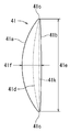
- the dimple 41 has a first side 41a, a second side 41b that faces the first side 41a, and both ends 41c that connect the first side 41a and the second side 41b.
- the first side 41a and the second side 41b are curved and are arranged in the width direction.
- the first side 41a and the second side 41b swell in different directions so as to be separated from each other.
- the dimple 41 has a first side 41a that swells in one side in the width direction and a second side 41b that swells in the other side in the width direction.
- the first side 41a is located in one region with respect to the line 41k connecting both ends 41c, and the whole or most of the second side 41b is located in the other region with respect to the line 41k.
- Both ends 22c of the dimple 22 shown in FIG. 5 connect the first side 22a and the second side 22b at an acute angle.
- both ends 41c of the dimple 41 shown in FIG. 19 connect the first side 41a and the second side 41b in a curved shape corresponding to the shape of the bottom blade 31a.
- the rotary cutting tool 1 may have a cutting edge 32 shown in FIG. 20 instead of the cutting edge 3 shown in FIG.
- the cutting edge 32 is located at a location deviated from the axis 5 of the main body 2 and protrudes in the axial direction from the tip 2 a of the main body 2.
- the cutting edge 32 protrudes in the axial direction from the tip of the groove 7 formed in the main body 2.
- the cutting edge 32 has a substantially triangular shape, and has a first bottom blade 32a positioned radially outward and a second bottom blade 32b positioned radially inward.
- the first bottom blade 32 a extends linearly from the vicinity of the outer peripheral edge of the main body 2 toward the axis 5.
- the first bottom blade 32 a has a first angle 32 d with respect to a plane orthogonal to the axis 5.
- the second bottom blade 32b extends linearly from the substantially radial center of the tip 2a of the main body 2 toward the outer peripheral edge.
- the second bottom blade 32 b has a second angle 32 e with respect to a plane orthogonal to the axis 5.
- the second angle 32e is larger than the first angle 32d and is, for example, 1.5 to 3 times the first angle 32d.
- the cutting edge 32 has a rake face 4 on a face continuous with the bottom of the groove 7.
- the cutting edge 32 has a flank on the opposite side of the rake face 4.
- the flank extends obliquely from the first bottom blade 32a and the second bottom blade 32b toward the tip 2a of the main body 2 in the same manner as the flank 8a, 8b shown in FIG.
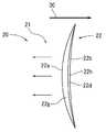
- the cutting edge 32 forms a dimple 42 shown in FIG. 21, for example.
- the dimple 42 has a first side 42a, a second side 42b opposite to the first side 42a, and both ends 42c connecting the first side 42a and the second side 42b.
- the first side 42a and the second side 42b are curved and are arranged in the width direction. Both the first side 42a and the second side 42b swell to one side in the width direction. The whole or most of the first side 42a and the second side 42b are located in one region with respect to the line 42k connecting both ends 42c. Both ends 42c connect the first side 42a and the second side 42b at an acute angle.
- the rotary cutting tool 1 may have a cutting edge 33 shown in FIG. 22 instead of the cutting edge 3 shown in FIG.
- the main body 2 of the rotary cutting tool 1 may have a tip 2b shown in FIG. 22 instead of the tip 2a shown in FIG.
- the tip 2 b of the main body 2 is inclined with respect to a plane orthogonal to the axis 5.
- the cutting edge 33 is located at the tip of the tip 2b in the axial direction.
- the cutting blade 33 has a bottom blade 33a that is located at a position deviated from the axis 5 of the main body 2 and is inclined with respect to a plane orthogonal to the axis 5 at substantially the same angle 33e as the tip 2b of the main body 2.
- the bottom blade 33a extends linearly from the substantially radial center of the tip 2b of the main body 2 toward the outer peripheral edge.
- the radially outer tip of the bottom blade 33a protrudes most in the axial direction.
- the cutting edge 33 has a rake face 4 in a face continuous with the bottom of the groove 7.
- the cutting edge 33 has a flank on the side opposite to the rake face 4.
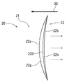
- the cutting edge 33 forms a dimple 43 shown in FIG. 23, for example.
- the dimple 43 has a first side 43a, a second side 43b that faces the first side 43a, and both ends 43c that connect the first side 43a and the second side 43b.
- the first side 43a and the second side 43b are arranged in the width direction.
- the first side 43a is a curve and swells in one side in the width direction.
- the second side 43b is also a curved line, and swells to one side in the width direction with respect to the line 43k connecting both ends 43c.
- the rotary cutting tool 1 may have a cutting edge 34 shown in FIG. 24 instead of the cutting edge 3 shown in FIG.
- the cutting edge 34 is located at a location deviated from the axis 5 of the main body 2, and protrudes in the axial direction from the tip 2 a of the main body 2.
- the cutting edge 34 protrudes in the axial direction from the tip of the groove 7 formed in the main body 2.
- the cutting edge 34 is substantially triangular, and includes a first bottom blade 34a positioned radially outward, a second bottom blade 34b positioned radially inward, a first bottom blade 34a, and a second bottom blade 34b. It has the 3rd bottom blade 34c connected in the shape of a curve.
- the first bottom blade 34 a extends linearly from the vicinity of the outer peripheral edge of the main body 2 toward the axis 5.
- the first bottom blade 34 a has a first angle 34 d with respect to a plane orthogonal to the axis 5.
- the second bottom blade 34b extends linearly from the substantially radial center of the tip 2a of the main body 2 toward the outer peripheral edge.
- the second bottom blade 34 b has a second angle 34 e with respect to a plane orthogonal to the axis 5.
- the second angle 34e is larger than the first angle 34d, and is, for example, 1.5 to 3 times the first angle 34d.
- the cutting edge 34 has a rake face 4 on a face continuous with the bottom of the groove 7.
- the cutting edge 34 has a flank on the opposite side of the rake face 4.
- the flank extends obliquely from the first bottom blade 34a, the second bottom blade 34b, and the third bottom blade 34c toward the tip 2a of the main body 2 in the same manner as the flank 8a, 8b shown in FIG.
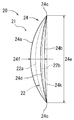
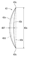
- the cutting edge 34 forms, for example, a dimple 44 shown in FIG.
- the dimple 44 has a first side 44a, a second side 44b facing the first side 44a, and both ends 44c connecting the first side 44a and the second side 44b.
- the first side 44a and the second side 44b are curved and are arranged in the width direction. Both the first side 44a and the second side 44b swell to one side in the width direction. The whole or most of the first side 44a and the second side 44b are located in one region with respect to the line 44k connecting both ends 44c. Both ends 44c are curved and smoothly connect the first side 44a and the second side 44b.
- the rotary cutting tool 1 may have a cutting edge 35 shown in FIG. 26 instead of the cutting edge 3 shown in FIG.
- the cutting edge 35 is located at a location deviated from the axis 5 of the main body 2 and protrudes in the axial direction from the tip 2 a of the main body 2.
- the cutting edge 35 has a substantially triangular shape, and has a first bottom blade 35 a extending from the outer peripheral edge of the main body 2 and a second bottom blade 35 b extending from a substantially central position in the radial direction of the main body 2.
- the first bottom blade 35a extends linearly from the vicinity of the outer peripheral edge of the main body 2 toward the axis 5.
- the first bottom blade 35 a has a first angle 35 d with respect to a plane orthogonal to the axis 5.
- the second bottom blade 35 b extends linearly from the substantially radial center of the main body 2 toward the axis 5.
- the second bottom blade 35 b has a second angle 35 e with respect to a plane orthogonal to the axis 5.
- the 2nd bottom blade 35b is extended toward the axial center 5 similarly to the 1st bottom blade 35a, and is located in a line with the 1st bottom blade 35a in the axial direction.
- the first bottom blade 35a and the second bottom blade 35b are connected at an acute angle by the bottom blade tip 35c.
- the first bottom blade 35a and the second bottom blade 35b are both positioned radially outward from the bottom blade tip 35c.
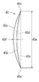
- the cutting edge 35 forms a dimple 45 shown in FIG. 27, for example.
- the dimple 45 has a first side 45a, a second side 45b facing the first side 45a, and both ends 45c connecting the first side 45a and the second side 45b.
- the first side 45a and the second side 45b are curved and are arranged in the width direction. Both the first side 45a and the second side 45b swell to one side in the width direction. The whole or most of the first side 45a and the second side 45b is located in one region with respect to the line 45k connecting both ends 45c.
- the dimple 45 has a groove bottom line 45d connecting the deepest positions in the width direction.
- the groove bottom line 45d is formed by a bottom blade tip 35c shown in FIG.
- the groove bottom line 45d is located at a location beyond the second side 45b rather than the region between the first side 45a and the second side 45b. Therefore, as shown in FIG. 6, the wear powder generated when the workpiece 20 and the counterpart material 30 are slid can be reliably held by the dimple 45.
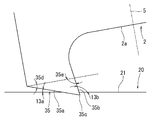
- the rotary cutting tool 1 may have a cutting edge 36 shown in FIG. 28 instead of the cutting edge 3 shown in FIG.
- the cutting edge 36 is located at a location deviated from the axis 5 of the main body 2 and protrudes in the axial direction from the tip 2 a of the main body 2.
- the cutting edge 36 has a substantially triangular shape, and includes a first bottom blade 36 a extending from the outer peripheral edge of the main body 2 and a second bottom blade 36 b extending from a substantially central position in the radial direction of the main body 2.
- the first bottom blade 36a extends linearly from the vicinity of the outer peripheral edge of the main body 2 in a direction away from the axis 5.
- the first bottom blade 36 a has a first angle 36 d with respect to a plane orthogonal to the axis 5.
- the second bottom blade 36b extends linearly in a direction away from the axial center 5 from a substantially radial center of the main body 2.
- the second bottom blade 36 b has a second angle 36 e with respect to a plane orthogonal to the axis 5. Similar to the first bottom blade 36a, the second bottom blade 36b extends radially outward and is aligned with the first bottom blade 36a in the axial direction.
- the first bottom blade 36a and the second bottom blade 36b are connected at an acute-angled bottom blade tip 36c.
- the first bottom blade 36a and the second bottom blade 36b are both located closer to the axis 5 than the bottom blade tip 36c.
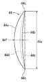
- the cutting edge 36 forms a dimple 46 shown in FIG. 29, for example.
- the dimple 46 has a first side 46a, a second side 46b facing the first side 46a, and both ends 46c connecting the first side 46a and the second side 46b.
- the first side 46a and the second side 46b are curved and are arranged in the width direction. Both the first side 46a and the second side 46b swell to one side in the width direction. The whole or most of the first side 46a and the second side 46b is located in one region with respect to the line 46k connecting both ends 46c.
- the dimple 46 has a groove bottom line 46d connecting the deepest positions in the width direction.
- the groove bottom line 46d is formed by a bottom blade tip 36c shown in FIG.
- the groove bottom line 46d is located at a location beyond the first side 46a rather than the region between the first side 46a and the second side 46b. Therefore, as shown in FIG. 6, the wear powder generated when the workpiece 20 and the counterpart material 30 are slid can be reliably held by the dimples 46.
- the rotary cutting tool 1 may have a cutting edge 37 shown in FIG. 30 instead of the cutting edge 3 shown in FIG.
- the cutting edge 37 is located at a location deviated from the axis 5 of the main body 2, and protrudes in the axial direction from the tip 2 a of the main body 2.
- the cutting edge 37 is substantially rectangular, and includes a first bottom blade 37a extending in the axial direction from the outer peripheral edge of the main body 2, and a second bottom blade 37b extending in the radial direction from the tip of the first bottom blade 37a.
- the third bottom blade 37c extends in the axial direction from the inner peripheral tip of the second bottom blade 37b.
- the first bottom blade 37a extends linearly from the vicinity of the outer peripheral edge of the main body 2 substantially in parallel with the axis 5.
- the second bottom blade 37b extends at an angle larger than 90 ° with respect to the first bottom blade 37a.
- the second bottom blade 37b is substantially parallel to the machining surface 21 when the axis 5 of the rotary cutting tool 1 is inclined at a predetermined angle 10 (see FIG. 1) with respect to the vertical line of the machining surface 21. To position. That is, the second bottom blade 37 b is inclined at an angle 10 with respect to a plane orthogonal to the axis 5.
- the third bottom blade 37c is substantially orthogonal to the inner peripheral tip of the second bottom blade 37b and extends linearly.
- the third bottom blade 37 c has an angle 37 e with respect to a line parallel to the axis 5.
- the distance between the first bottom blade 37a and the third bottom blade 37c decreases as the distance from the second bottom blade 37b increases.
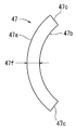
- the cutting edge 37 forms, for example, a dimple 47 shown in FIG.
- the dimple 47 has a first side 47a, a second side 47b facing the first side 47a, and both ends 47c connecting the first side 47a and the second side 47b.
- the first side 47a and the second side 47b are curved and are arranged in the width direction. Both the first side 47a and the second side 47b swell in one side in the width direction and are substantially parallel. Therefore, the dimple 47 has a substantially constant width and extends in a C shape. Both ends 47c of the dimple 47 are substantially linear.
- the rotary cutting tool 1 may have a cutting edge 38 shown in FIG. 32 instead of the cutting edge 3 shown in FIG.
- the cutting edge 38 is located at a location deviated from the axis 5 of the main body 2 and protrudes in the axial direction from the tip 2 a of the main body 2.
- the cutting edge 38 is polygonal and has a first bottom edge 38a, a second bottom edge 38b, and a third bottom edge 38c in succession.
- the first bottom blade 38 a extends linearly from the vicinity of the outer peripheral edge of the main body 2 toward the axis 5.
- the first bottom blade 38 a has a first angle 38 d with respect to a surface perpendicular to the axis 5 from the vicinity of the outer peripheral edge of the main body 2.
- the second bottom blade 38b extends linearly from the tip of the first bottom blade 38a and further away from the main body 2 and toward the axis 5.
- the second bottom blade 38 b has a second angle 38 e that is smaller than the first angle 38 d with respect to a plane perpendicular to the axis 5.
- the third bottom blade 38c linearly connects the tip of the second bottom blade 38b and the substantially center of the main body 2 in the radial direction.
- the third bottom blade 38 c has a third angle 38 f with respect to a plane perpendicular to the axis 5.
- the rotary cutting tool 1 may have one cutting edge 3 as shown in FIG. 2 or the like, or may have a plurality of cutting edges 39a and 39b as shown in FIG.
- the cutting edge 39a and the cutting edge 39b are located, for example, at locations facing each other with the axis 5 interposed therebetween.
- the cutting edge 39a and the cutting edge 39b are positioned at a predetermined distance in the circumferential direction, for example.
- the cutting edge 39a is formed, for example, in the same manner as the cutting edge 31 shown in FIG.
- the cutting edge 39b is formed similarly to the cutting edge 32 shown in FIG. 20, for example.
- dimples 48 and 49 shown in FIG. 34 can be formed by using the rotary cutting tool 1 shown in FIG.
- the rotary cutting tool 1 is set so that the rotary cutting tool 1 is at a predetermined angle 10 with respect to the vertical line of the machining surface 21.
- the workpiece 20 and the rotary cutting tool 1 are relatively moved while rotating the rotary cutting tool 1 about the axis 5.
- the cutting edge 39 a forms the dimple 48
- the cutting edge 39 b forms the dimple 49.
- the dimples 48 and the dimples 49 are alternately arranged in the relative movement direction of the rotary cutting tool 1 with respect to the workpiece 20.
- the dimple 48 has two opposite sides, and the two opposite sides swell in a direction away from each other.
- the dimple 49 has two opposite sides and extends so that the two opposite sides swell in the same direction.
- the dimples 48 and 49 are arranged side by side in a direction orthogonal to the respective longitudinal directions.
- the dimple 34 may be configured to form the dimples 50 and 51 shown in FIG. 35 instead of the dimples 48 and 49 shown in FIG. 34, and the workpiece 20 may be processed by the rotary cutting tool 1.
- the dimple 50 has two opposite sides and extends so that the two opposite sides swell in the same direction.
- the dimple 50 has a length L1 in the cutting direction (longitudinal direction).
- the dimple 51 has a crescent shape similar to that of the dimple 50, and has a length L2 in the cutting direction (longitudinal direction) shorter than that of the dimple 50.
- the dimples 50 and 51 are alternately arranged in a direction orthogonal to the longitudinal direction of the dimple 50.
- the rotary cutting tool 1 can be provided with a plurality of types of cutting edges so as to form a plurality of types of dimples.
- a plurality of rotary cutting tools are prepared, and cutting blades having different shapes are provided on each rotary cutting tool.
- the workpiece 20 may be processed using a plurality of rotary cutting tools, and each shape of dimple may be formed by each rotary cutting tool.
- the dimples are formed by a plurality of first dimples 48, 50 formed by cutting edges and other cutting edges different from the cutting edges, and are located between the first dimples 48, 50.
- Second dimples 49 and 51 are included. Accordingly, dimples having different shapes are alternately arranged. Thereby, as shown in FIG. 6, the frictional resistance caused by the relative movement of the workpiece 20 and the counterpart material 30 can be more effectively reduced.
- the first dimples 48 and 50 may be formed using a first rotary cutting tool
- the second dimples 49 and 51 may be formed using a second rotary cutting tool.
- the position and rotation angle of the second rotary cutting tool are set to the position and rotation angle of the first rotary cutting tool so that the positions of the first dimples 48 and 50 and the second dimples 49 and 51 have a predetermined relationship. It is necessary to make adjustments while taking this into consideration.
- the first rotary cutting tool and the second rotary cutting tool may have different shapes of cutting edges.
- the first dimples 48 and 50 and the second dimples 49 and 51 are formed by cutting blades 39a and 39b having different shapes. Then, as shown in FIG. 33, these cutting edges 39a and 39b may be provided in the same rotary cutting tool 1. In this case, the positional relationship between the plurality of cutting edges 39 a and 39 b is determined in advance in the rotary cutting tool 1. Therefore, dimples having different shapes can be easily formed at predetermined positions as compared with the case where a plurality of rotary cutting tools are controlled in consideration of the mutual positional relationship.
- the plurality of dimples 22 shown in FIG. 12 are arranged side by side in a direction substantially orthogonal to the longitudinal direction of the dimples 22.
- the plurality of dimples may be arranged in the pattern shown in FIGS.
- the plurality of dimples 60 shown in FIG. 36 have first dimples 60a arranged in one row and second dimples 60b arranged in one row.
- the first dimples 60a are arranged so that the longitudinal direction is inclined with respect to the feed direction indicated by the arrow.
- the plurality of first dimples 60a are arranged in parallel in the feeding direction at predetermined intervals, and the respective longitudinal directions are arranged in parallel.
- the second dimple 60b is inclined at a different angle from the first dimple 60a with respect to the feed direction.
- the plurality of second dimples 60b are arranged in parallel in the feed direction at a predetermined interval, and the respective longitudinal directions are arranged in parallel.
- the second dimple 60b is located in a shape and location that is symmetrical to the first dimple 60a with respect to a line 60c extending between the first dimple 60a arranged in a row and the second dimple 60b arranged in a row.
- the 37 has a first dimple 61a arranged in one row and a second dimple 61b arranged in one row.
- the first dimples 61a are arranged so that the longitudinal direction is inclined with respect to the feed direction indicated by the arrow.
- the plurality of first dimples 61a are arranged in parallel in the feeding direction at a predetermined interval, and the respective longitudinal directions are arranged in parallel.
- the second dimple 61b is inclined at a different angle from the first dimple 61a with respect to the feed direction.
- the second dimple 61b is inclined at an angle symmetrical to the first dimple 61a with respect to a line 61c extending between the first dimple 61a arranged in a row and the second dimple 61b arranged in a row.
- the plurality of second dimples 61b are arranged in parallel in the feeding direction at a predetermined interval, and the respective longitudinal directions are arranged in parallel.
- the plurality of first dimples 61a and the plurality of second dimples 61b are alternately arranged in the feed direction indicated by the arrows.
- the positions of the first dimple 61a and the second dimple 61b in the direction orthogonal to the feeding direction are determined so as to partially overlap when viewed in the feeding direction.
- the plurality of dimples 62 shown in FIG. 38 have first dimples 62a arranged in one row and second dimples 62b arranged in one row.
- the first dimples 62a are arranged so that the longitudinal direction is inclined with respect to the feed direction indicated by the arrow.
- the plurality of first dimples 62a are arranged in parallel in the feeding direction at a predetermined interval, and the respective longitudinal directions are arranged in parallel.
- the second dimple 62b is inclined at an angle different from that of the first dimple 62a with respect to the feed direction.
- the longitudinal end of the first dimple 62a and the longitudinal end of the second dimple 62b are in contact with each other.
- the first dimple 62a and the second dimple 62b are located at symmetrical positions with respect to a line 62c extending between the first dimple 62a arranged in a row and the second dimple 62b arranged in a row, and have a symmetrical angle. Having a symmetrical shape.
- the plurality of dimples 63 shown in FIG. 39 have first dimples 63a arranged in one row and second dimples 63b arranged in one row.
- the first dimples 63a are arranged so that the longitudinal direction is inclined with respect to the feed direction indicated by the arrow.
- the plurality of first dimples 63a are arranged in parallel in the feeding direction at a predetermined interval, and the respective longitudinal directions are arranged in parallel.
- the second dimple 63b is inclined at an angle different from that of the first dimple 63a with respect to the feed direction. A portion of the end portion in the longitudinal direction of the first dimple 63a and the end portion in the longitudinal direction of the second dimple 63b overlap each other. Thereby, the first dimple 63a and the second dimple 63b are continuous.
- the first dimple 63a and the second dimple 63b are located at symmetrical positions with respect to a line 63c extending between the first dimple 63a arranged in a row and the second dimple 63b arranged in a row, and have a symmetrical angle. Having a symmetrical shape.
- first dimple 64a arranged in a row and a second dimple 64b arranged in a row.
- the first dimples 64a are arranged so that the longitudinal direction is inclined with respect to the feed direction indicated by the arrow.
- the plurality of first dimples 64a are arranged in parallel in the feeding direction at a predetermined interval, and the respective longitudinal directions are arranged in parallel.
- the second dimple 64b is inclined at an angle different from that of the first dimple 64a with respect to the feed direction, and intersects the first dimple 64a.
- the first dimple 64a and the second dimple 64b are located at symmetrical positions with respect to the line 64c connecting the intersecting points, have a symmetrical angle, and have a symmetrical shape.
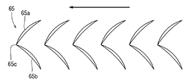
- first dimple 65a arranged in a row and a second dimple 65b arranged in a row.
- the first dimples 65a are arranged so that the longitudinal direction is inclined with respect to the feed direction indicated by the arrow.
- the plurality of first dimples 65a are arranged in parallel in the feed direction at a predetermined interval, and the respective longitudinal directions are arranged in parallel.
- the second dimple 65b is inclined at a different angle from the first dimple 65a with respect to the feed direction.
- the end portion in the longitudinal direction of the first dimple 65a and the end portion in the longitudinal direction of the second dimple 65b are in contact at a common point 65c.
- the second dimple 65b has a positional relationship and shape obtained by rotating the first dimple 65a around the common point 65c.
- the cutting edge 3 shown in FIG. 2 etc. is provided in the vicinity of the outer periphery of the main body 2. Instead of this, the cutting edge may be provided in the vicinity of the center of the main body 2 in the radial direction. As shown in FIG. 1, the cutting edge 3 is located at a location where the entire cutting edge 3 is off the axis 5. Instead of this, the cutting edge 3 may be located at a position where the bottom edge is detached from the axis 5 while at least a part thereof is located at the axis 5.
- the cutting blade may have a triangular bottom blade shown in FIG. 2 or the like, or an arc-shaped bottom blade shown in FIG. Instead of this, the cutting edge may have a bottom edge having a free curved shape or a combination of a plurality of shapes.
- the rake face of the cutting edge may be parallel to the axis or may be inclined with respect to a plane parallel to the axis.
- the plurality of dimples may be completely separated as shown in FIG. 12, or may be separated from the second dimple while partially overlapping with the first dimple as shown in FIG.
- the dimples may be arranged at regular intervals as shown in FIG. 12, or may be arranged at irregular intervals.
- the rotary cutting tool 1 may have one cutting edge 3 as shown in FIG. 2, or may have two cutting edges 39a and 39b as shown in FIG. It may replace with this and the rotary cutting tool 1 may have three or more cutting blades spaced apart in the circumferential direction.
- the main body 2 of the rotary cutting tool 1 may have a round bar shape as shown in FIG. 1 or may have a bar shape with a polygonal cross section.
- the processed surface 21 may be a flat surface as shown in FIG. 1, or may be a cylindrical or cylindrical outer peripheral surface or inner peripheral surface as shown in FIG.
- dimples may be formed on the outer peripheral surface of the journal bearing shaft.
- Dimples may be formed on the inner peripheral surface of the bearing.
- Dimples may be formed on the pump parts that rotate.
- Dimples may be formed on the outer peripheral surface of the piston skirt.
- the rotary cutting tool 1 and the workpiece 20 can be relatively sent.
- the rotary cutting tool 1 and the workpiece 20 may be relatively sent by moving the rotary cutting tool 1 relative to the workpiece 20, for example, by moving it in the circumferential direction.
- the feed speed is slower than the cutting speed of the cutting edge determined by the rotational speed of the rotary cutting tool 1, and is, for example, 1 to 20 m / min.
Landscapes
- Engineering & Computer Science (AREA)
- Mechanical Engineering (AREA)
- Turning (AREA)
- Milling Processes (AREA)
Abstract
回転切削工具(1)を用いて被加工材(20)にディンプル(22)を形成するディンプル加工方法である。棒状の本体(2)の先端でかつ軸心(5)からずれた位置から軸方向に突出する切れ刃(3)を備える回転切削工具(1)を準備する。回転切削工具(1)の軸心(5)が被加工材(20)の加工面(21)の垂直線に対して傾斜するように回転切削工具(1)をセットする。軸心(5)を中心に回転切削工具(1)を回転させつつ回転切削工具(1)が加工面(21)に沿って移動するように回転切削工具(1)と被加工材(20)を相対的に送る。切れ刃(3)によって加工面(21)を切削して相互に離間するディンプル(22)を加工面(21)に形成する。
Description
本発明は、被加工材の表面に回転切削工具によって微小な凹みであるディンプルを形成するディンプル加工方法に関する。
アルミ、銅合金、それらの鋳造品、鋳鉄、樹脂などの被加工材の表面に多数の微小な凹みであるディンプルを形成する場合がある。例えば複数のディンプルによって梨地模様を被加工材の表面に形成する場合がある。被加工材にディンプルを形成することで、被加工材に接触する相手材と被加工材の間に生じる摩擦抵抗を小さくすることができるためである。その原理は、例えば被加工材と相手材が接触することで摩耗粉が生じ、摩耗粉が被加工材と相手材との間に挟まって摩擦抵抗を大きくする場合がある。この摩耗粉をディンプル内に収容させることで、摩耗粉によって摩擦抵抗が高くなることを抑制できる。あるいは被加工材と相手材との間に油が注入され、油がディンプルに充填される場合がある。相手材がディンプルの近傍を通過すると、油がディンプルから高い圧力で相手材と被加工材の間に排出される(スクイーズ効果)。この圧力によって相手材が被加工材に対して接触し難くなり、これにより相手材と被加工材の間の摩擦抵抗が小さくなる。
そのためエンジンのシリンダやターボチャージャー等の筒状部材の内壁や人工関節の接合面等にディンプルを形成する場合がある。ディンプルを加工する方法としては、レーザ照射による方法、微小球を被加工材に高速で衝突させるショットピーニングによる方法等が知られている。しかしレーザ照射を利用する場合、被加工材が高温で加熱されるために、被加工材に大きな熱応力が生じるという問題や被加工材にドロス(溶融物)が付着するという問題がある。そしてレーザによって生じる膨らみやドロスを除去するのは困難である。ショットピーニングを利用する場合は、ディンプルの周りが膨らんで被加工材が平坦でなくなる場合がある。またディンプルを含む周囲に残留応力が発生し、被加工材の変形あるいは破損の原因になるおそれもある。
特開平10-052998号公報では、フライス、エンドミル等の回転切削工具を利用して被加工材の表面を加飾する方法が開示されている。この方法では、回転切削工具を回転させつつ被加工材の表面にわずかに回転切削工具の切れ刃を当てる。これにより被加工材の表面に例えば複数の円を有する水玉模様を形成できる。そして円は、例えば回転切削工具の軸方向に並設するように形成され、かつ軸方向に直交する送り方向にも等間隔に形成される。
従来、ディンプルによって摩擦抵抗をより均一に低下させたいとの要望がある。そのため例えば非常に小さい複数のディンプルを容易に形成できる加工方法が望まれている。またディンプルの周りにバリが発生し難い、あるいはディンプルの周りを平坦にしたいという要望もある。そのため回転切削工具を用いて、例えば非常に小さい複数のディンプルを形成できる加工方法が従来必要とされている。
本発明の1つの特徴は、回転切削工具を用いて被加工材にディンプルを形成するディンプル加工方法に関する。棒状の本体の先端でかつ軸心からずれた位置から軸方向に突出する切れ刃を備える回転切削工具を準備する。回転切削工具の軸心が被加工材の加工面の垂直線に対して傾斜するように回転切削工具をセットする。軸心を中心に回転切削工具を回転させつつ回転切削工具が加工面に沿って移動するように回転切削工具と被加工材を相対的に送る。切れ刃によって加工面を切削することで加工面に相互に離間するディンプルを形成する。
したがって回転切削工具は、棒状であって先端に軸方向に突出する切れ刃を有する。そのため径方向に突出する切れ刃に比べて切れ刃を小さい径で回転させることができる。その結果、切れ刃によって小さいディンプルを形成できる。切れ刃は、本体の先端の軸心からずれた位置から突出している。そのため回転切削工具を加工面に対して傾けて回転させることで切れ刃は、加工面を切削したり加工面から離れたりする。これにより相互に離間する複数のディンプルを容易に形成できる。
本発明の1つの実施形態を図1~12にしたがって説明する。図1に示す回転切削工具1は、離間した複数のディンプル(微小な凹み)22を形成するための回転切削工具である。回転切削工具1は、棒状の本体2と、本体2の先端2aから突出する切れ刃(底刃)3を有する。本体2は、丸棒状あるいは円柱状であって、直径が2~10mm、例えば4mmである。本体2は、軸心5に対して略直交する先端(底面)2aを有する。軸心5は、本体2の横断面の中心に位置し、長手方向に延出する。
図2,3に示すように切れ刃3は、本体2の軸心5から外れた場所に位置し、本体2の先端2aから軸方向に突出する。切れ刃3は、本体2に形成された溝(フルート)7に連続して形成され、溝7の先端から軸方向に突出する。切れ刃3は、略三角形であって、径方向外方に位置する第1底刃3aと径方向内方に位置する第2底刃3bを有する。第1底刃3aは、本体2の先端2aの外周縁あるいは外周縁の近傍から軸心5に向けて直線状に斜めに延出する。第1底刃3aは、軸心5に直交する面に対して軸方向に第1角度3dを有する。
図2に示すように第2底刃3bは、第1底刃3aと軸心5の間に位置し、本体2の径方向略中心から外周縁に向けて直線状に延出する。第2底刃3bは、軸心5に直交する面に対して軸方向に第2角度3eを有する。第1角度3dと第2角度3eは、鋭角であって、例えば1~30°、具体的には15°である。第1底刃3aと第2底刃3bは、底刃先端3cにおいて角度を有して連結される。
図2,3に示すように切れ刃3は、溝7の底と連続する面においてすくい面4を有する。切れ刃3は、すくい面4の反対側に逃げ面8を有する。逃げ面8は、第1底刃3aから延出する第1逃げ面8aと、第2底刃3bから延出する第2逃げ面8bを有する。第1逃げ面8aは、第1底刃3aから本体2の先端2aに向けて斜めに延出する。第2逃げ面8bは、略三角形であって、第2底刃3bから本体2の先端2aに向けて斜めに延出する。第1逃げ面8aは、第1逃げ面8aと第2逃げ面8bの稜線に対して第1角度3fを有する。第2逃げ面8bは、稜線に対して第2角度3gを有する。第1角度3fと第2角度3gは、回転切削工具1を被加工材20に対して送る際に被加工材20の切削面が第1逃げ面8aと第2逃げ面8bに干渉しない大きさに設定される。例えば第1角度3fと第2角度3gは、第1逃げ面8aと第2逃げ面8bを軸心5に直交する面に投影した際に、20±10°の大きさに設定される。
切れ刃3は、回転切削工具1の本体2と同一の材質から形成、あるいは異なる材質から形成される。例えば、切れ刃3と本体2が、工具鋼、高速度鋼(高速度工具鋼)、超硬合金から形成される。あるいは本体2が、炭素鋼、ステンレス鋼、工具鋼、高速度鋼、超硬合金から形成され、切れ刃3が多結晶ダイヤ(PCD)、立方晶窒化ホウ素(CBN)、セラミックスから形成され、切れ刃3が本体2に接合される。あるいは切れ刃3が本体2と同一または異なる材料で形成され、切れ刃3に対応する領域にコーティング等の表面処理が施される。表面処理は、例えば化学気相蒸着法(CVD)や物理蒸着法(PVD)等によって施され、TiAlN、TiAlCrN、TiAlCrSiNなどのTi系、CVDダイヤモンド、ダイヤモンドライクカーボン(DLC)等のコーティング層が切れ刃3として用いられる。
図1,4に示すように回転切削工具1は、軸心5が被加工材20の加工面21の垂直線に対して所定の角度10を有するようにセットされる。回転切削工具1は、切れ刃3の先端が加工面21に対して所定の深さ11になるようにセットされる。回転切削工具1は、軸心5を中心に回転され、切れ刃3が所定の回転角度領域において加工面21を削る。他の回転角度領域において切れ刃3が加工面21から離れる。これにより切れ刃3が加工面21を断続的に切削する。回転切削工具1が1回転する毎に、1つの切れ刃3が1つのディンプルを作成する。
図1,4に示す所定の角度(傾斜角度)10は、切れ刃3が加工面21から離れるように0°より大きく、例えば1°以上、2°以上、5°以上に設定される。所定の角度10は、切れ刃3が加工面21を削るように、好ましくは図5に示すようにディンプル22が所定の長さ22eを有するように、60°以下、45°以下、30°以下に設定される。所定の深さ11は、図6に示すようにディンプル22の最大深さが、例えば0.1~0.001mm、具体的には0.01mmとなるよう設定される。
図5,6に示すようにディンプル22は、非常に小さく、切削方向における長さ22eが例えば0.5~1mmである。切削方向は、図1を参照するように切れ刃3が加工面21に対して進行する方向であり、例えば切れ刃3の所定部分が加工面21に到達した点と加工面21から離れた点を結んだ方向である。ディンプル22は、切削方向に対して直交する幅を有する。幅の最大である最大幅22fは、長さ22eより短く、例えば長さ22eの半分以下である。最大幅22fは、例えば0.01~0.5mmである。
ディンプル22は、図5に示すように第1辺22aと、第1辺22aに対向する第2辺22bと、第1辺22aと第2辺22bを連結する両端22cを有する。第1辺22aと第2辺22bは、曲線であって、幅方向に並ぶ。第1辺22aと第2辺22bは、同一方向に膨らみ、換言すると第1辺22aが幅方向の一方に膨らみ、第2辺22bが幅方向の一方に凹む。これによりディンプル22は、三日月状になっている。第1辺22aと第2辺22bの全部または大部分は、両端22cを結んだ線22kにおいて一方側の領域に位置する。
ディンプル22は、図6に示すように第1辺22aから延出する第1傾斜面22gと、第2辺22bから延出する第2傾斜面22hを有する。第1傾斜面22gは、加工面21に対して第1深さ角度22iを有し、第1辺22aから第2辺22bに向けて徐々に深くなる。第2傾斜面22hは、加工面21に対して第2深さ角度22jを有し、第2辺22bから第1辺22aに向けて徐々に深くなる。第2深さ角度22jは、第1深さ角度22iよりも大きい。ディンプル22は、幅方向で最も深い部分を結んだ溝底線22dを有し、溝底線22dは、ディンプル22の幅方向の中心を結んだ線よりも第2辺22bに近い場所に位置する。
図7に示すようにディンプル22を有する被加工材20と、被加工材20に対向する相手材30を相対的に移動させる際に生じる摩擦は、ディンプル22によって軽減される。例えば被加工材20と相手材30が摺動することで、両部材の一方または両方から摩耗粉が生じ、その摩耗粉がディンプル22内に保持される。摩耗粉の多くは、溝底線22dの近傍に保持される。
図7に示すように被加工材20を相手材30に対して幅方向一方側、具体的にはディンプル22の第1辺22aの膨らむ方向へ移動させる場合がある。この場合、摩耗粉は、相手材30と同様にディンプル22に対して第1辺22aから第2辺22bに向けて移動する。第2傾斜面22hは、第1傾斜面22gよりも傾斜角度が大きい。そのため摩耗粉は、第2傾斜面22hによってディンプル22から排出されることが効果的に抑制される。
図8に示すように被加工材20を相手材30に対して幅方向他方側、具体的にはディンプル22の第1辺22aの膨らむ方向と反対方向へ移動させる場合がある。この場合、ディンプル22を通過するグリースは、相手材30と同様にディンプル22に対して第2辺22bから第1辺22aに向けて移動する。
第1傾斜面22gは、第2傾斜面22hよりも傾斜角度が緩い。そのためグリースは、第1傾斜面22gを利用して徐々に圧力が上昇する。例えば第2傾斜面22hを利用して圧力が上昇する場合に比べて、圧力の上昇率が小さい。そのため圧力損失が少なく、グリースの圧力が確実に高くなる。その結果、グリースの圧力によるスクイーズ効果が大きくなり、被加工材20と相手材30の間における摩擦を効率良く軽減できる。
被加工材20は、例えば図9に示すように円筒状であって、外周面20aと内周面20bを有する。被加工材20は、軸方向の一端に平らな加工面21を有し、加工面21に複数のディンプル22が形成される。複数のディンプル22は、周方向に並ぶとともに被加工材20の径方向にも並ぶ。複数のディンプル22は、例えば渦巻状に加工面21に形成され、周方向および径方向に並設される。
図10に示すように回転切削工具1は、加工装置70に装着される。加工装置70は、X軸ガイド71と、X軸ガイド71に沿って移動可能なX方向移動部材72と、X方向移動部材72に対してY軸方向に移動するY方向移動部材73と、Y方向移動部材73に対してZ軸方向に移動するZ方向移動部材74を有する。X軸ガイド71は、図示省略の支持台に保持されてX軸方向に延設する。なおX軸方向とY軸方向とZ軸方向は、相互に直交する関係にある。
X方向移動部材72は、例えば送りねじ機構のナット部材を有する。ナット部材は、サーボモータ96(図11参照)によって回転してX軸ガイド71に設けられたねじ軸に対して移動する。あるいはX方向移動部材72は、ラックピニオン機構とサーボモータ96を利用してX軸ガイド71に対して移動する。Y方向移動部材73とZ方向移動部材74は、例えば送りねじ機構、ラックピニオン機構、サーボモータ97,98(図11参照)を利用してX方向移動部材72に対してY方向およびZ方向に移動する。
図10に示すように加工装置70は、Z方向移動部材74に角度調整可能に装着される揺動部材75と、揺動部材75に軸回転可能に設けられるスピンドル76を有する。揺動部材75は、サーボモータ99(図11参照)を利用してZ方向移動部材74に対してX方向あるいはY方向に揺動する。回転切削工具1がスピンドル76に装着され、スピンドル76がサーボモータ100(図11参照)を利用して回転切削工具1を軸心5中心に回転させる。加工装置70の各部材の移動または回転は、図11に示すPC90内に格納された制御部93によって制御される。
図10に示すように被加工材20は、ワーク保持装置80に保持される。ワーク保持装置80は、基台81と、基台81の上面に回転可能に装着されたテーブル82を有する。テーブル82は、サーボモータ101(図11参照)等を利用して基台81に対して回転する。被加工材20がテーブル82に装着され、テーブル82がサーボモータ101を利用して被加工材20とともに被加工材20の軸心20cを中心に回転する。サーボモータ101は、PC90内に格納された制御部93によって制御される。
加工装置70とワーク保持装置80の各部材の移動制御、回転制御は、PC90内の制御部(CPU)93により、I/F回路94を介して制御される。ROM95には、制御部93の実行に必要な命令やデータが格納されている。加工態様に関するデータや被加工材20の座標データ、スピンドル76の回転数等に関するデータがキーボード等を介して入力され、I/F回路91を経由して記憶部(RAM)92に格納される。制御部93は、格納データに基づいて各モータ96~101に所定の駆動指令を送信し、送信信号に基づいて各モータ96~101が所定の駆動動作を行う。
図1,9に示すように回転切削工具1の軸心5が加工面21に対して所定の角度10になるように設定される。回転切削工具1は、切れ刃3による加工面21の切削深さを考慮して深さ方向(Z方向)の位置が決定される。回転切削工具1を所定の回転速度で回転させつつ、被加工材20を所定の回転速度で回転させる。同時に回転切削工具1を被加工材20の外周面20aから内周面20bに向けて移動させる。
図9に示すように回転切削工具1が1回転して、切れ刃3が加工面21を切削し、ディンプル22が1つ形成される。加工面21が回転切削工具1に対して回転し、加工面21が回転切削工具1に対して送られる。回転切削工具1が回転して、切れ刃3によってディンプル22が形成される。これにより複数のディンプル22が相互に離間した状態で形成される。
図1,9に示すように回転切削工具1は、被加工材20の送り方向、すなわち被加工材20の回転方向に傾いている。そのためディンプル22は、その長手方向が被加工材20の送り方向に対して略直交するように形成される。複数のディンプル22は、送り方向および幅方向に並設される。回転切削工具1は、加工面21に対して径方向、例えば外周面20aから内周面20bに向けて移動する。そのため複数のディンプル22は、加工面21において渦巻状に並び、周方向および径方向に並ぶ。
回転切削工具1の回転速度と、被加工材20の回転速度と、回転切削工具1の径方向への移動速度は、複数の離間したディンプル22の間隔が等しくなるように調整され得る。例えば、回転切削工具1が被加工材20の外周面20aの近傍に位置する場合、回転切削工具1を高速で回転させる。そして回転切削工具1が被加工材20の内周面20bに近づくに連れて回転切削工具1の回転速度を遅くする。
具体的には、被加工材20の外周径が49mm、内周径が13mmの場合において、被加工材20を17rpmで回転させる。回転切削工具1を被加工材20の外周面20a近傍から内周面20bに向けて径方向に等速で移動させる。回転切削工具1を径方向に移動させるとともに、回転切削工具1の回転速度を5100rpmから1360rpmに徐々に減速させる。これにより複数のディンプル22の間隔がほぼ等しくなる。前記方法に代えて、回転切削工具1の回転速度を一定にし、回転切削工具1を外周面20a近傍から内周面20bに向けて径方向に移動させる。そして回転切削工具1が内周面20bに近づくにつれて被加工材20の回転速度を徐々に速くすることもできる。この方法により複数のディンプル22の間隔をほぼ等しくすることができる。
図12に示すように小さなディンプル22は、幅方向(図12の横方向)に順に形成される。これにより複数の離間したディンプル22は、被加工材20の加工面21において幅方向に並設される。ディンプル22は、加工面21に渦巻状に並ぶように形成され、径方向(図12の縦方向)にも略等間隔で並設される。ディンプル22は、例えば加工面21の10-30%の面積を占めるように、具体的には約20%を占めるようにその数および位置が決定される。
ディンプル22が形成された加工面21は、被加工材20が製品として使用される際、図7,8を参照するように相手材30と対向する。加工面21は、例えば被加工材20の軸心20c(図9参照)を中心として相手材30に対して回転される。ディンプル22は、非円形であるために、指向性を有し、複数のディンプル22は、相対移動する相手材30に対して同一方向を向いている。
例えば図7に示すように相手材30は、ディンプル22に対して第1辺22aから第2辺22bに向けて移動する。複数のディンプル22は、相対回転する相手材30に対して同一方向を向いている。したがって複数のディンプル22は、相手材30に対して同様の効果を奏する。図7に代えて図8に示すように相手材30がディンプル22に対して第2辺22bから第1辺22aに向けて移動しても良い。この場合も複数のディンプル22は、相対回転する相手材30に対して同一方向を向いている。したがって複数のディンプル22は、相手材30に対して同様の効果を奏する。
図6に示すように被加工材20にディンプル22を形成する。ディンプル22は、被加工材20に接触する相手材30と被加工材20の間に生じる摩擦抵抗を小さくすることができる。例えば図7,8を参照するように被加工材20と相手材30が接触することで摩耗粉が生じ、摩耗粉が被加工材20と相手材30との間に挟まって摩擦抵抗が大きくなる場合がある。この摩耗粉がディンプル22内に保持されることで、摩耗粉によって摩擦抵抗が上昇することが抑制され得る。
あるいは図6に示すように被加工材20と相手材30との間に油が注入され、油がディンプル22に充填される。したがってディンプル22によって油を保持することができ、被加工材20と相手材30が油を介さずに接触することを防止、あるいは被加工材20と相手材30が摩耗粉を介して凝着することを防止できる。相手材30がディンプル22の近傍を通過すると、油がディンプル22から高い圧力で相手材30と被加工材20の間に排出され、潤滑膜を形成する(スクイーズ効果)。この圧力によって相手材30が被加工材20に対して接触し難くなり、相手材30と被加工材20の間の摩擦抵抗が小さくなる。
上述するように本形態は、図1に示すように回転切削工具1を用いて被加工材20にディンプル22を形成するディンプル加工方法に関する。棒状の本体2の先端でかつ軸心5からずれた位置から軸方向に突出する切れ刃3を備える回転切削工具1を準備する。回転切削工具1の軸心5が被加工材20の加工面21の垂直線に対して傾斜するように回転切削工具1をセットする。軸心5を中心に回転切削工具1を回転させつつ回転切削工具1が加工面21に沿って移動するように回転切削工具1と被加工材20を相対的に送る。切れ刃3によって加工面21を切削して相互に離間するディンプル22を加工面21に形成する。
したがって回転切削工具1は、棒状であって先端に軸方向に突出する切れ刃3を有する。そのため径方向に突出する切れ刃に比べて切れ刃3を小さい径で回転させることができる。その結果、切れ刃3によって小さいディンプル22を形成できる。切れ刃3は、本体2の先端の軸心5からずれた位置から突出している。そのため回転切削工具1を加工面21に対して傾けて回転させることで切れ刃3は、加工面21を切削したり加工面21から離れたりする。これにより相互に離間する複数のディンプル22を容易に形成できる。
図1を参照するように切れ刃3は、加工面21に対して斜めに被加工材20に進入し、徐々に加工面21を深く切削する。そして切れ刃3は、徐々に加工面21を浅く切削し、斜めに被加工材20から退避する。したがってディンプル22は、図5を参照するように両端22cにおいて浅く、長さ方向の略中央において深くなる。例えば加工面にレーザを照射して形成したディンプル、あるいはショットピーニングによって形成したディンプルは、加工面に対して略直角である急激な角度を有する。このようなディンプルに比べ、ディンプル22は、加工面21に対して急激な角度を有しない。その結果、ディンプル22は、加工面21に対して急激な角度変化を有さず、グリースの圧力によるスクイーズ効果を発揮しやすい。
図1を参照するように切れ刃3は、回転切削工具1の回転に伴って加工面21に対して切削開始点(例えば図5の両端22cの1つ)から切削を開始し、切削終点(例えば両端22cの他の1つ)から加工面21に対して離れる。ディンプル22は、切削開始点と切削終点を結んだ線22kに対して直交する方向に対面する第1辺22aと第2辺22bを有する。第1辺22aは、結んだ線22kに対して一方向に膨らむように湾曲する。第2辺22bは、結んだ線22kに沿って延出あるいは前記一方向に膨らむように湾曲している。
したがって図5に示すようにディンプル22は、円形でなく、指向性を有する形状、例えば三日月状になっている。そのため図6に示すようにディンプル22の方向を考慮して、ディンプル22に対する相手材30の移動方向を決定できる。かくして被加工材20と相手材30の相対移動の際に被加工材20と相手材30の間に生じる摩擦抵抗をより小さくすることができる。しかも指向性を有するディンプル22は、切れ刃3を本体2の先端の軸心5からずれた位置から突出させ、回転切削工具1を加工面21に対して傾けて回転させることで形成できる。そのため指向性を有するディンプル22が容易かつ確実に形成され得る。
図1を参照するように回転切削工具1の軸心5が被加工材20の加工面21の垂直線に対して60°以下の傾斜角度を有するように回転切削工具1をセットする。したがって回転切削工具1は、例えば軸心5が加工面21と並行とされる場合に比べて、加工面21に対して垂直に近い角度で当たる。そのため回転切削工具1に加わる曲げ応力が小さくなる。その結果、回転切削工具1の径を比較的小さくすることができる。そして小さい回転切削工具1によってより小さいディンプル22を形成できる。一方、回転切削工具1の軸心5は、被加工材20の加工面21の垂直線に対して傾斜している。そのため切れ刃3を加工面21から離すことができ、これにより相互に離間する複数のディンプル22を形成できる。
図5に示すようにディンプル22は、回転切削工具1の切削方向である長さ22eと、切削方向に対して直交する幅の最大値で長さ22eよりも短い最大幅22fと、長さ22eの10%以下の最大深さを有する。したがって回転切削工具1によって細長いディンプル22が形成される。そしてディンプル22の長さ22eは、回転切削工具1の切削方向、すなわち回転切削工具1の本体2の周長さに依存する。そのため回転切削工具1によって幅の狭いディンプル22が形成される。
図5に示すようにディンプル22は、回転切削工具1の切削方向に対して直交する方向に対面する2辺22a,22bを有する。2辺22a,22bは、同一方向に湾曲している。したがってディンプル22は、指向性を有し、指向性を利用することで加工面21に良好な特性を与えることができる。
図5に示すようにディンプル22は、回転切削工具1の切削方向である長さ22eと、切削方向に対して直交する幅と、各幅において最も深い点を結んだ深さ溝底線22dを有する。溝底線22dが幅の中心から外れている。したがって摩耗粉を補集する効果とスクイーズ効果を考慮しつつ、溝底線22dを所定の位置に設定できる。かくして被加工材20と相手材30の間に生じる摩擦係数を効果的に軽減することができる。
例えば、図6に示すようにディンプル22の傾斜面22g,22hの角度は、溝底線22dの位置に対応して決定される。例えば溝底線22dをディンプル22の2辺22a,22bの一方に近接させることで、傾斜面22g,22hの1つの角度が大きくなり、他の1つの角度が小さくなる。したがって溝底線22dの位置を幅の中心から外すことで、スクイーズ効果の大きいディンプル22を得ることができ、これにより被加工材20と相手材30の間の摩擦抵抗を小さくすることができる。
図2に示すように回転切削工具1は、径方向外方に位置する第1底刃3aと径方向内方に位置する第2底刃3bを有する。ディンプル22は、第1底刃3aによって形成される第1辺22a(図5参照)と、第2底刃3bによって形成される第2辺22bを有する。第1辺22aと第2辺22bは、同一方向に湾曲している。これによりディンプル22が三日月状になっている。
図6に示すようにディンプル22は、相手材30と被加工材20の間に形成される摩擦抵抗を軽減できる。摩擦抵抗は、ディンプル22の数、加工面21に対するディンプル22の面積率、ディンプル22の分散状態等に影響を受け得る。ディンプル22は、比較的小さい。そのためディンプル22の加工面21に対する面積率を容易に調整できる。あるいはディンプル22は、加工面21に対して容易に均等に分散され得る。
図5に示すようにディンプル22は、対角線が最長となる直線、例えば両端22cを結んだ線22kを有する。ディンプル22の形状は、対角線が最長となる直線に対する同一側の領域にディンプル22の輪郭線の大部分、例えば半分以上が位置する。したがってディンプル22は、指向性を有し、図6に示す相手材30に対して所望の効果を奏し得る。
図9に示すように回転切削工具1は、加工面21に対して傾斜しており、その傾斜方向は、回転切削工具1の被加工材20に対する相対送り方向と一致している。そのため図12に示すようにディンプル22の長手方向は、相対送り方向に対して略直交する。複数のディンプル22は、相対送り方向に並設される。
図12に示すパターンに代えて、複数のディンプル22を図13,14に示すパターンで配列させても良い。例えば、図13のパターンは、回転切削工具1の加工面21に対する相対送り方向に対して回転切削工具1を斜めに設定する。詳しくは回転切削工具1の軸心5を加工面21に投影させた線が回転切削工具1の加工面21に対する相対送り方向と平行な線に対して角度を有する。例えば、図9,10において回転切削工具1を加工面21に対してX方向とY方向に傾斜させる。
図14のパターンは、回転切削工具1の加工面21に対する相対送り方向にディンプル22の長手方向が延出する。詳しくは回転切削工具1の軸心5を加工面21に投影させた線が回転切削工具1の加工面21に対する相対送り方向と平行な線に対して直交する。例えば図9において回転切削工具1を加工面21の左右領域に設置し、図10を参照するようにX方向にのみ傾斜させる。あるいは図9において回転切削工具1を加工面21の上下領域に設置し、図10を参照するようにY方向にのみ傾斜させる。これによりディンプル22の長手方向が回転切削工具1の加工面21に対する送り方向と略平行になる。複数のディンプル22は、長手方向に順に形成され、長手方向に並設される。回転切削工具1は、図9を参照するように加工面21に対して径方向にも移動させる。そのため複数のディンプル22は、図14に示すように径方向(上下方向)にも並設される。
図9に示す被加工材20に代えて図15に示す被加工材23に複数のディンプル22を形成しても良い。被加工材23は、加工面23aである外周面を有する。加工面23aに対して垂直な線に対して角度10を有するように回転切削工具1をセットする。回転切削工具1を軸心5中心に回転させつつ、被加工材23を軸心中心に回転させる。回転切削工具1を被加工材23に対して軸方向にも移動させる。
これにより図15に示す被加工材23の加工面23aには、複数のディンプル22が周方向に並列されかつ軸方向にも並設される。すなわち複数のディンプル22は、加工面23aにおいて螺旋状に配設される。
図2に示す第1角度3dと第2角度3eは、所定の角度に設定することができる。例えば、第1角度3dと第2角度3eを15°に設定した場合、図5に示すディンプル22が形成され得る。第1角度3dと第2角度3eを20°に設定した場合は、図16に示すディンプル24が形成され得る。
図16に示すようにディンプル24は、第1辺24aと第2辺24bと両端24cを有する。第1辺24aは、曲線であって、点線で示す第1辺22aよりも曲率が大きい。第2辺24bは、曲線であって、点線で示す第2辺22bよりも曲率が小さく、両端24cを結んだ線24kに近接する。したがってディンプル24は、点線で示すディンプル22の幅よりも大きな幅24fを有する。ディンプル24の長さ24eは、点線で示すディンプル22の長さとほぼ同じである。幅方向で最も深い部分を結んだ溝底線24dは、第2辺24bに近い場所に位置する。
回転切削工具1は、図2に示す切れ刃3に代えて図17に示す切れ刃31を有していても良い。切れ刃31は、本体2の軸心5から外れた場所に位置し、本体2の先端2aから軸方向に突出する。切れ刃31は、本体2に形成された溝7の先端から軸方向に突出する。切れ刃31は、略円弧形状の底刃31aを有する。切れ刃31は、溝7の底と連続する面においてすくい面4を有する。切れ刃31は、図18に示すようにすくい面4の反対側に逃げ面31bを有する。逃げ面31bは、底刃31aから本体2の先端2aに向けて斜めに延出する。
図17,18に示す切れ刃31は、例えば図19に示すディンプル41を形成する。ディンプル41は、第1辺41aと、第1辺41aに対向する第2辺41bと、第1辺41aと第2辺41bを連結する両端41cを有する。第1辺41aと第2辺41bは、曲線であって、幅方向に並ぶ。第1辺41aと第2辺41bは、相互に離れるように異なる方向に膨らむ。
ディンプル41は、図19に示すように幅方向の一方に膨らむ第1辺41aと、幅方向の他方に膨らむ第2辺41bを有する。第1辺41aは、両端41cを結んだ線41kに対して一方領域に位置し、第2辺41bの全部または大部分は、線41kに対して他方領域に位置する。図5に示すディンプル22の両端22cは、鋭角に第1辺22aと第2辺22bを連結する。これに対して図19に示すディンプル41の両端41cは、底刃31aの形状に対応して第1辺41aと第2辺41bを曲線状に連結する。
回転切削工具1は、図2に示す切れ刃3に代えて図20に示す切れ刃32を有していても良い。切れ刃32は、本体2の軸心5から外れた場所に位置し、本体2の先端2aから軸方向に突出する。切れ刃32は、本体2に形成された溝7の先端から軸方向に突出する。切れ刃32は、略三角形であって、径方向外方に位置する第1底刃32aと径方向内方に位置する第2底刃32bを有する。
図20に示すように第1底刃32aは、本体2の外周縁近傍から軸心5に向けて直線状に延出する。第1底刃32aは、軸心5に直交する面に対して第1角度32dを有する。第2底刃32bは、本体2の先端2aの径方向略中心から外周縁に向けて直線状に延出する。第2底刃32bは、軸心5に直交する面に対して第2角度32eを有する。第2角度32eは、第1角度32dよりも大きく、例えば第1角度32dの1.5~3倍である。
図20に示すように切れ刃32は、溝7の底と連続する面においてすくい面4を有する。切れ刃32は、すくい面4の反対側に逃げ面を有する。逃げ面は、図3に示す逃げ面8a,8bと同様に第1底刃32aと第2底刃32bから本体2の先端2aに向けて斜めに延出する。切れ刃32は、例えば図21に示すディンプル42を形成する。
図21に示すようにディンプル42は、第1辺42aと、第1辺42aに対向する第2辺42bと、第1辺42aと第2辺42bを連結する両端42cを有する。第1辺42aと第2辺42bは、曲線であって、幅方向に並ぶ。第1辺42aと第2辺42bは、いずれも幅方向の一方に膨らむ。第1辺42aと第2辺42bの全体または大部分は、両端42cを結んだ線42kに対して一方領域に位置する。両端42cは、鋭角に第1辺42aと第2辺42bを連結する。
回転切削工具1は、図2に示す切れ刃3に代えて図22に示す切れ刃33を有していても良い。回転切削工具1の本体2は、図2に示す先端2aに代えて図22に示す先端2bを有していても良い。本体2の先端2bは、軸心5に直交する面に対して斜めになっている。切れ刃33は、先端2bの軸方向の先端に位置する。切れ刃33は、本体2の軸心5から外れた場所に位置し、本体2の先端2bと略同一の角度33eにて軸心5に直交する面に対して傾斜する底刃33aを有する。
図22に示すように底刃33aは、本体2の先端2bの径方向略中心から外周縁に向けて直線状に延出する。底刃33aの径方向外方先端が最も軸方向に突出している。切れ刃33は、溝7の底と連続する面においてすくい面4を有する。切れ刃33は、すくい面4の反対側に逃げ面を有する。切れ刃33は、例えば図23に示すディンプル43を形成する。
図23に示すようにディンプル43は、第1辺43aと、第1辺43aに対向する第2辺43bと、第1辺43aと第2辺43bを連結する両端43cを有する。第1辺43aと第2辺43bは、幅方向に並ぶ。第1辺43aは、曲線であって、幅方向の一方に膨らむ。第2辺43bも、曲線であって、両端43cを結んだ線43kに対して幅方向の一方に膨らむ。
回転切削工具1は、図2に示す切れ刃3に代えて図24に示す切れ刃34を有していても良い。切れ刃34は、本体2の軸心5から外れた場所に位置し、本体2の先端2aから軸方向に突出する。切れ刃34は、本体2に形成された溝7の先端から軸方向に突出する。切れ刃34は、略三角形であって、径方向外方に位置する第1底刃34aと径方向内方に位置する第2底刃34bと、第1底刃34aと第2底刃34bを曲線状に連結する第3底刃34cを有する。
図24に示すように第1底刃34aは、本体2の外周縁近傍から軸心5に向けて直線状に延出する。第1底刃34aは、軸心5に直交する面に対して第1角度34dを有する。第2底刃34bは、本体2の先端2aの径方向略中心から外周縁に向けて直線状に延出する。第2底刃34bは、軸心5に直交する面に対して第2角度34eを有する。第2角度34eは、第1角度34dよりも大きく、例えば第1角度34dの1.5~3倍である。
図24に示すように切れ刃34は、溝7の底と連続する面においてすくい面4を有する。切れ刃34は、すくい面4の反対側に逃げ面を有する。逃げ面は、図3に示す逃げ面8a,8bと同様に第1底刃34aと第2底刃34bと第3底刃34cから本体2の先端2aに向けて斜めに延出する。切れ刃34は、例えば図25に示すディンプル44を形成する。
図25に示すようにディンプル44は、第1辺44aと、第1辺44aに対向する第2辺44bと、第1辺44aと第2辺44bを連結する両端44cを有する。第1辺44aと第2辺44bは、曲線であって、幅方向に並ぶ。第1辺44aと第2辺44bは、いずれも幅方向の一方に膨らむ。第1辺44aと第2辺44bの全体または大部分は、両端44cを結んだ線44kに対して一方領域に位置する。両端44cは、曲線状であって、第1辺44aと第2辺44bを滑らかに連結する。
回転切削工具1は、図2に示す切れ刃3に代えて図26に示す切れ刃35を有していても良い。切れ刃35は、本体2の軸心5から外れた場所に位置し、本体2の先端2aから軸方向に突出する。切れ刃35は、略三角形であって、本体2の外周縁から延出する第1底刃35aと、本体2の径方向略中心位置から延出する第2底刃35bを有する。
図26に示すように第1底刃35aは、本体2の外周縁近傍から軸心5に向けて直線状に延出する。第1底刃35aは、軸心5に直交する面に対して第1角度35dを有する。第2底刃35bは、本体2の径方向略中心から軸心5に向けて直線状に延出する。第2底刃35bは、軸心5に直交する面に対して第2角度35eを有する。第2底刃35bは、第1底刃35aと同様に軸心5に向けて延出しており、第1底刃35aと軸方向に並んでいる。第1底刃35aと第2底刃35bは、底刃先端35cによって鋭角に連結される。第1底刃35aと第2底刃35bは、いずれも底刃先端35cよりも径方向外方に位置する。切れ刃35は、例えば図27に示すディンプル45を形成する。
図27に示すようにディンプル45は、第1辺45aと、第1辺45aに対向する第2辺45bと、第1辺45aと第2辺45bを連結する両端45cを有する。第1辺45aと第2辺45bは、曲線であって、幅方向に並ぶ。第1辺45aと第2辺45bは、いずれも幅方向の一方に膨らむ。第1辺45aと第2辺45bの全体または大部分は、両端45cを結んだ線45kに対して一方領域に位置する。
図27に示すようにディンプル45は、幅方向において最も深い位置を結んだ溝底線45dを有する。溝底線45dは、図26に示す底刃先端35cによって形成される。溝底線45dは、第1辺45aと第2辺45bの間領域よりも第2辺45bを越えた場所に位置する。したがって図6を参照するように被加工材20と相手材30を摺動させた際に生じる摩耗粉は、ディンプル45によって確実に保持され得る。
回転切削工具1は、図2に示す切れ刃3に代えて図28に示す切れ刃36を有していても良い。切れ刃36は、本体2の軸心5から外れた場所に位置し、本体2の先端2aから軸方向に突出する。切れ刃36は、略三角形であって、本体2の外周縁から延出する第1底刃36aと、本体2の径方向略中心位置から延出する第2底刃36bを有する。
図28に示すように第1底刃36aは、本体2の外周縁近傍から軸心5から離れる方向に直線状に延出する。第1底刃36aは、軸心5に直交する面に対して第1角度36dを有する。第2底刃36bは、本体2の径方向略中心から軸心5から離れる方向に直線状に延出する。第2底刃36bは、軸心5に直交する面に対して第2角度36eを有する。第2底刃36bは、第1底刃36aと同様に径方向外方に延出しており、第1底刃36aと軸方向に並んでいる。第1底刃36aと第2底刃36bは、鋭角の底刃先端36cにおいて連結される。第1底刃36aと第2底刃36bは、いずれも底刃先端36cよりも軸心5に近い場所に位置する。切れ刃36は、例えば図29に示すディンプル46を形成する。
図29に示すようにディンプル46は、第1辺46aと、第1辺46aに対向する第2辺46bと、第1辺46aと第2辺46bを連結する両端46cを有する。第1辺46aと第2辺46bは、曲線であって、幅方向に並ぶ。第1辺46aと第2辺46bは、いずれも幅方向の一方に膨らむ。第1辺46aと第2辺46bの全体または大部分は、両端46cを結んだ線46kに対して一方領域に位置する。
図29に示すようにディンプル46は、幅方向において最も深い位置を結んだ溝底線46dを有する。溝底線46dは、図28に示す底刃先端36cによって形成される。溝底線46dは、第1辺46aと第2辺46bの間領域よりも第1辺46aを越えた場所に位置する。したがって図6を参照するように被加工材20と相手材30を摺動させた際に生じる摩耗粉は、ディンプル46によって確実に保持され得る。
回転切削工具1は、図2に示す切れ刃3に代えて図30に示す切れ刃37を有していても良い。切れ刃37は、本体2の軸心5から外れた場所に位置し、本体2の先端2aから軸方向に突出する。切れ刃37は、略四角形であって、本体2の外周縁から軸方向に延出する第1底刃37aと、第1底刃37aの先端から径方向に延出する第2底刃37bと、第2底刃37bの内周先端から軸方向に延出する第3底刃37cを有する。
図30に示すように第1底刃37aは、本体2の外周縁近傍から軸心5と略並行に直線状に延出する。第2底刃37bは、第1底刃37aに対して90°より大きい角度にて延出する。第2底刃37bは、回転切削工具1の軸心5を加工面21の垂直線に対して所定の角度10(図1参照)で傾斜させた際に加工面21と略並行となるように位置する。すなわち第2底刃37bは、軸心5に直交する面に対して角度10で傾斜する。
図30に示すように第3底刃37cは、第2底刃37bの内周先端から略直交し、直線状に延出する。第3底刃37cは、軸心5と並行な線に対して角度37eを有する。第1底刃37aと第3底刃37cの間隔は、第2底刃37bに近接するほど狭くなる。切れ刃37は、例えば図31に示すディンプル47を形成する。
図31に示すようにディンプル47は、第1辺47aと、第1辺47aに対向する第2辺47bと、第1辺47aと第2辺47bを連結する両端47cを有する。第1辺47aと第2辺47bは、曲線であって、幅方向に並ぶ。第1辺47aと第2辺47bは、いずれも幅方向の一方に膨らみ、略並行である。したがってディンプル47は、幅が略一定であって、C字状に延出する。ディンプル47の両端47cは、略直線状である。
回転切削工具1は、図2に示す切れ刃3に代えて図32に示す切れ刃38を有していても良い。切れ刃38は、本体2の軸心5から外れた場所に位置し、本体2の先端2aから軸方向に突出する。切れ刃38は、多角形であって、第1底刃38aと第2底刃38bと第3底刃38cを連続して有する。第1底刃38aは、本体2の外周縁近傍から軸心5に向けて直線状に延出する。第1底刃38aは、本体2の外周縁近傍から軸心5に対して垂直となる面に対して第1角度38dを有する。
図32に示すように第2底刃38bは、第1底刃38aの先端から直線状に延出し、さらに本体2から離れかつ軸心5に向けてする。第2底刃38bは、軸心5に対して垂直となる面に対して第1角度38dよりも小さい第2角度38eを有する。第3底刃38cは、第2底刃38bの先端と本体2の径方向略中心とを直線状に連結する。第3底刃38cは、軸心5に対して垂直となる面に対して第3角度38fを有する。
回転切削工具1は、図2等に示すように1つの切れ刃3を有していても良いし、図33に示すように複数の切れ刃39a,39bを有していても良い。切れ刃39aと切れ刃39bは、例えば軸心5を介して対向する場所に位置する。あるいは切れ刃39aと切れ刃39bは、例えば周方向に所定の距離離れて位置する。切れ刃39aは、例えば図17に示す切れ刃31と同様に形成される。切れ刃39bは、例えば図20に示す切れ刃32と同様に形成される。
図33に示す回転切削工具1を用いることで、例えば図34に示すディンプル48,49を形成できる。例えば図1に示すように回転切削工具1を加工面21の垂直線に対して所定の角度10となるように回転切削工具1をセットする。回転切削工具1を軸心5中心に回転させつつ被加工材20と回転切削工具1を相対的に移動させる。これにより切れ刃39aがディンプル48を形成し、切れ刃39bがディンプル49を形成する。ディンプル48とディンプル49は、回転切削工具1の被加工材20に対する相対移動方向に交互に並ぶ。
図34に示すようにディンプル48は、対向する2辺を有し、対向する2辺が相互に離れる方向に膨らむ。ディンプル49は、対向する2辺を有し、対向する2辺が同じ方向に膨らむように延出する。ディンプル48,49は、各長手方向に対して直交する方向に並設される。
図34に示すディンプル48,49に代えて図35に示すディンプル50,51を形成するように回転切削工具1を構成し、その回転切削工具1によって被加工材20を加工しても良い。ディンプル50は、対向する2辺を有し、対向する2辺が同じ方向に膨らむように延出する。ディンプル50は、切削方向(長手方向)において長さL1を有する。ディンプル51は、ディンプル50と同様の三日月状であって、ディンプル50よりも短い切削方向(長手方向)の長さL2を有する。ディンプル50,51は、ディンプル50の長手方向に対して直交する方向に交互に並ぶ。
図34,35に示すように複数種類の形状のディンプルを形成するように回転切削工具1に複数種類の形状の切れ刃を設けることができる。あるいは複数の回転切削工具を準備し、各回転切削工具に異なる形状の切れ刃を設ける。そして複数の回転切削工具を用いて、被加工材20を加工し、各回転切削工具によって各形状のディンプルを形成しても良い。
図34,35に示すようにディンプルは、切れ刃によって形成される複数の第1ディンプル48,50と、切れ刃と異なる他の切れ刃によって形成されかつ第1ディンプル48,50の間に位置する第2ディンプル49,51を含む。したがって形状が異なるディンプルが交互に配設される。これにより図6を参照するように被加工材20と相手材30の相対移動によって生じる摩擦抵抗をより効果的に減少させること等ができる。
第1ディンプル48,50を第1の回転切削工具を用いて形成し、第2ディンプル49,51を第2の回転切削工具を用いて形成することもできる。この場合、第1ディンプル48,50と第2ディンプル49,51の位置が所定の関係となるように、第2の回転切削工具の位置と回転角度を第1の回転切削工具の位置と回転角度を考慮しつつ調整する必要がある。第1の回転切削工具と第2の回転切削工具は、異なる形状の切れ刃を有していても良い。
図34,35を参照するように第1ディンプル48,50と第2ディンプル49,51を異なる形状の切れ刃39a,39bによって形成する。そして図33に示すようにこれら切れ刃39a,39bを同じ回転切削工具1に設けても良い。この場合、複数の切れ刃39a,39bの位置関係は、回転切削工具1において予め定められる。そのため相互の位置関係を考慮しつつ複数の回転切削工具を制御する場合に比べて、異なる形状のディンプルを容易に所定の位置に形成することができる。
図12に示す複数のディンプル22は、ディンプル22の長手方向に対して略直交する方向に並設される。これに代えて複数のディンプルは、図36~図41に示すパターンで配設されても良い。図36に示す複数のディンプル60は、1列に並ぶ第1ディンプル60aと、1列に並ぶ第2ディンプル60bを有する。第1ディンプル60aは、矢印で示す送り方向に対して長手方向が傾斜するように配列される。複数の第1ディンプル60aは、送り方向に所定間隔で並設され、各長手方向が並行に配列される。
図36に示すように第2ディンプル60bは、送り方向に対して第1ディンプル60aと異なる角度で傾斜する。複数の第2ディンプル60bは、送り方向に所定間隔で並設され、各長手方向が並行に配列される。第2ディンプル60bは、1列に並ぶ第1ディンプル60aと1列に並ぶ第2ディンプル60bの間を延出する線60cに対して第1ディンプル60aと対称となる形状および場所に位置する。
図37に示す複数のディンプル61は、1列に並ぶ第1ディンプル61aと、1列に並ぶ第2ディンプル61bを有する。第1ディンプル61aは、矢印で示す送り方向に対して長手方向が傾斜するように配列される。複数の第1ディンプル61aは、送り方向に所定間隔で並設され、各長手方向が並行に配列される。第2ディンプル61bは、送り方向に対して第1ディンプル61aと異なる角度で傾斜する。例えば第2ディンプル61bは、1列に並ぶ第1ディンプル61aと1列に並ぶ第2ディンプル61bの間を延出する線61cに対して第1ディンプル61aと対称となる角度で傾斜する。複数の第2ディンプル61bは、送り方向に所定間隔で並設され、各長手方向が並行に配列される。
図37に示すように複数の第1ディンプル61aと複数の第2ディンプル61bは、矢印で示す送り方向に対して交互に配置される。第1ディンプル61aと第2ディンプル61bの送り方向に直交する方向の位置は、これらを送り方向に見た際に一部重なるように決定される。
図38に示す複数のディンプル62は、1列に並ぶ第1ディンプル62aと、1列に並ぶ第2ディンプル62bを有する。第1ディンプル62aは、矢印で示す送り方向に対して長手方向が傾斜するように配列される。複数の第1ディンプル62aは、送り方向に所定間隔で並設され、各長手方向が並行に配列される。
図38に示すように第2ディンプル62bは、送り方向に対して第1ディンプル62aと異なる角度で傾斜する。第1ディンプル62aの長手方向の端部と、第2ディンプル62bの長手方向の端部は、接している。第1ディンプル62aと第2ディンプル62bは、1列に並ぶ第1ディンプル62aと1列に並ぶ第2ディンプル62bの間を延出する線62cに対して対称の場所に位置し、対称の角度を有し、対称の形状を有する。
図39に示す複数のディンプル63は、1列に並ぶ第1ディンプル63aと、1列に並ぶ第2ディンプル63bを有する。第1ディンプル63aは、矢印で示す送り方向に対して長手方向が傾斜するように配列される。複数の第1ディンプル63aは、送り方向に所定間隔で並設され、各長手方向が並行に配列される。
図39に示すように第2ディンプル63bは、送り方向に対して第1ディンプル63aと異なる角度で傾斜する。第1ディンプル63aの長手方向の端部と、第2ディンプル63bの長手方向の端部は、その一部が重なっている。これにより第1ディンプル63aと第2ディンプル63bが連続している。第1ディンプル63aと第2ディンプル63bは、1列に並ぶ第1ディンプル63aと1列に並ぶ第2ディンプル63bの間を延出する線63cに対して対称の場所に位置し、対称の角度を有し、対称の形状を有する。
図40に示す複数のディンプル64は、1列に並ぶ第1ディンプル64aと、1列に並ぶ第2ディンプル64bを有する。第1ディンプル64aは、矢印で示す送り方向に対して長手方向が傾斜するように配列される。複数の第1ディンプル64aは、送り方向に所定間隔で並設され、各長手方向が並行に配列される。
図40に示すように第2ディンプル64bは、送り方向に対して第1ディンプル64aと異なる角度で傾斜し、第1ディンプル64aと交差する。第1ディンプル64aと第2ディンプル64bは、交差する点を結んだ線64cに対して相互に対称の場所に位置し、対称の角度を有し、対称の形状を有する。
図41に示す複数のディンプル65は、1列に並ぶ第1ディンプル65aと、1列に並ぶ第2ディンプル65bを有する。第1ディンプル65aは、矢印で示す送り方向に対して長手方向が傾斜するように配列される。複数の第1ディンプル65aは、送り方向に所定間隔で並設され、各長手方向が並行に配列される。
図41に示すように第2ディンプル65bは、送り方向に対して第1ディンプル65aと異なる角度で傾斜する。第1ディンプル65aの長手方向の端部と、第2ディンプル65bの長手方向の端部は、共通点65cにおいて接している。第2ディンプル65bは、共通点65cを中心として第1ディンプル65aを回転させた位置関係および形状を有する。
図2等に示す切れ刃3は、本体2の外周縁の近傍に設けられている。これに代えて切れ刃は、本体2の径方向中央近傍に設けられても良い。図1に示すように切れ刃3は、その全体が軸心5から外れた場所に位置する。これに代えて切れ刃3は、その少なくとも一部が軸心5に位置しつつ底刃が軸心5から外れた場所に位置していても良い。
切れ刃は、図2等に示す三角形状の底刃、図17等に示す円弧形状の底刃を有していても良い。これに代えて切れ刃は、自由曲線状、複数の形状を組合せた形状の底刃を有していても良い。切れ刃のすくい面は、軸線に対して平行であっても良いし、軸線と平行な面に対して傾いていても良い。
複数のディンプルは、図12に示すように完全に離間していても良いし、図39に示すように第1のディンプルと一部重なりつつ、第2のディンプルと離間していても良い。ディンプルは、図12に示すように等間隔に並んでいても良いし、不等間隔で並んでいても良い。
回転切削工具1は、図2に示すように1つの切れ刃3を有していても良いし、あるいは図33に示すように2つの切れ刃39a,39bを有していても良い。これに代えて回転切削工具1は、周方向に離間する3つ以上の切れ刃を有していても良い。
回転切削工具1の本体2は、図1に示すように丸棒状であっても良いし、あるいは断面多角形の棒状等であっても良い。
加工面21は、図1に示すように平面でも良いし、図15に示すように円筒または円柱の外周面または内周面であっても良い。例えば、ジャーナル軸受の軸の外周面にディンプルを形成しても良い。軸受の内周面にディンプルを形成しても良い。回転運動するポンプの部品にディンプルを形成しても良い。ピストンのスカートの外周面にディンプルを形成しても良い。
図9に示すように回転切削工具1に対して被加工材20を回転させることで、回転切削工具1と被加工材20を相対的に送ることができる。これに代えて、回転切削工具1を被加工材20に対して移動、例えば周方向に移動させることで、回転切削工具1と被加工材20を相対的に送っても良い。送り速度は、回転切削工具1の回転速度によって決定される切れ刃の切削速度に比べて遅く、例えば1~20m/分等である。
添付の図面を参照して詳細に上述した種々の実施例は、本発明の代表例であって本発明を限定するものではありません。詳細な説明は、本教示の様々な態様を作成、使用および/または実施するために、当業者に教示するものであって、本発明の範囲を限定するものではありません。更に、上述した各付加的な特徴および教示は、改良された回転切削工具および/またはその製造方法と使用方法を提供するため、別々にまたは他の特徴および教示と一緒に適用および/または使用され得るものです。
Claims (7)
- 回転切削工具を用いて被加工材にディンプルを形成するディンプル加工方法であって
棒状の本体の先端でかつ軸心からずれた位置から軸方向に突出する切れ刃を備える前記回転切削工具を準備し、
前記回転切削工具の前記軸心が前記被加工材の加工面の垂直線に対して傾斜するように前記回転切削工具をセットし、
前記軸心を中心に前記回転切削工具を回転させつつ前記回転切削工具が前記加工面に沿って移動するように前記回転切削工具と前記被加工材を相対的に送り、前記切れ刃によって前記加工面を切削することで前記加工面に相互に離間するディンプルを形成するディンプル加工方法。 - 請求項1に記載のディンプル加工方法であって、
前記切れ刃は、前記回転切削工具の回転に伴って前記加工面に対して切削開始点から切削を開始し、切削終点から前記加工面に対して離れ、
前記ディンプルは、前記切削開始点と前記切削終点を結んだ線に対して直交する方向に対面する第1辺と第2辺を有し、前記第1辺は、前記結んだ線に対して一方向に膨らむように湾曲し、前記第2辺は、前記結んだ線に沿って延出あるいは前記一方向に膨らむように湾曲しているディンプル加工方法。 - 請求項1または2に記載のディンプル加工方法であって、
前記回転切削工具の前記軸心は、前記被加工材の前記加工面の前記垂直線に対して60°以下の傾斜角度を有するように前記回転切削工具をセットするディンプル加工方法。 - 請求項1~3のいずれか1つに記載のディンプル加工方法であって、
前記ディンプルは、前記回転切削工具の切削方向である長さと、前記切削方向に対して直交する幅の最大値で前記長さよりも短い最大幅と、前記長さの10%以下の最大深さを有するディンプル加工方法。 - 請求項1~4のいずれか1つに記載のディンプル加工方法であって、
前記ディンプルは、前記回転切削工具の切削方向である長さと、前記切削方向に対して直交する幅と、前記幅において最も深い点を結んだ溝底線を有し、前記溝底線が前記幅の中心から外れた場所に位置するディンプル加工方法。 - 請求項1~5のいずれか1つに記載のディンプル加工方法であって、
前記ディンプルは、前記切れ刃によって形成される複数の第1ディンプルと、前記切れ刃と異なる他の切れ刃によって形成されかつ前記複数の第1ディンプルの間に位置する第2ディンプルを含むディンプル加工方法。 - 請求項6に記載のディンプル加工方法であって、
前記切れ刃と前記他の切れ刃は、同一の前記回転切削工具に設けられているディンプル加工方法。
Priority Applications (4)
| Application Number | Priority Date | Filing Date | Title |
|---|---|---|---|
| US16/301,785 US10702931B2 (en) | 2016-05-19 | 2017-05-15 | Dimple processing method using rotary cutting tool |
| EP17799335.9A EP3459664A4 (en) | 2016-05-19 | 2017-05-15 | METHOD FOR FORMING LOW PRESSURES USING A ROTARY CUTTING TOOL |
| JP2018518285A JP6651616B2 (ja) | 2016-05-19 | 2017-05-15 | 回転切削工具を用いたディンプル加工方法 |
| CN201780031002.9A CN109153086B (zh) | 2016-05-19 | 2017-05-15 | 使用了旋转切削工具的凹坑加工方法 |
Applications Claiming Priority (2)
| Application Number | Priority Date | Filing Date | Title |
|---|---|---|---|
| JP2016-100404 | 2016-05-19 | ||
| JP2016100404 | 2016-05-19 |
Publications (1)
| Publication Number | Publication Date |
|---|---|
| WO2017199911A1 true WO2017199911A1 (ja) | 2017-11-23 |
Family
ID=60325152
Family Applications (1)
| Application Number | Title | Priority Date | Filing Date |
|---|---|---|---|
| PCT/JP2017/018204 Ceased WO2017199911A1 (ja) | 2016-05-19 | 2017-05-15 | 回転切削工具を用いたディンプル加工方法 |
Country Status (5)
| Country | Link |
|---|---|
| US (1) | US10702931B2 (ja) |
| EP (1) | EP3459664A4 (ja) |
| JP (1) | JP6651616B2 (ja) |
| CN (1) | CN109153086B (ja) |
| WO (1) | WO2017199911A1 (ja) |
Cited By (3)
| Publication number | Priority date | Publication date | Assignee | Title |
|---|---|---|---|---|
| US20180154461A1 (en) * | 2015-06-29 | 2018-06-07 | Kanefusa Kabushiki Kaisha | Dimples processing method by means of end milling and end mill |
| WO2019202911A1 (ja) * | 2018-04-18 | 2019-10-24 | 兼房株式会社 | ディンプル付き被加工物及びディンプル加工方法 |
| JP2022550342A (ja) * | 2019-09-25 | 2022-12-01 | ビー グリーン パッケージング カンパニー リミテッド | カバー及びその製造方法 |
Families Citing this family (4)
| Publication number | Priority date | Publication date | Assignee | Title |
|---|---|---|---|---|
| DE102017124187A1 (de) * | 2017-10-17 | 2019-04-18 | Kendrion (Villingen) Gmbh | Verfahren zum Herstellen von einer oder mehreren konkaven Ausnehmungen auf einem insbesondere im Wesentlichen zylindrischen Grundkörper insbesondere auf einem Magnetanker, Stößel oder einer Rückschlussplatte, Magnetanker, Stößel oder Rückschlussplatten, welcher eine oder mehrere nach diesem Verfahren hergestellte Ausnehmungen aufweist, sowie elektro-magnetischer Aktuator mit einem derartigen Magnetanker und/ oder einer derartigen Rückschlussplatte |
| JP6625156B2 (ja) * | 2018-03-30 | 2019-12-25 | 株式会社牧野フライス製作所 | 摺動面の窪み加工用工具および窪み加工方法 |
| US20210394390A1 (en) * | 2018-09-17 | 2021-12-23 | David G.P. BEAVEN | Asymmetrical corner joint and tools for making same |
| EP4029638A4 (en) * | 2019-09-13 | 2023-10-11 | Kanefusa Kabushiki Kaisha | METHOD FOR DIMP PROCESSING |
Citations (3)
| Publication number | Priority date | Publication date | Assignee | Title |
|---|---|---|---|---|
| JPH1052998A (ja) * | 1996-08-08 | 1998-02-24 | Kanefusa Kk | 回転切削工具による被加工材表面の加飾方法 |
| JP2003084370A (ja) * | 2001-09-12 | 2003-03-19 | Masami Masuda | 異方性ディンプル面 |
| JP2008246587A (ja) * | 2007-03-29 | 2008-10-16 | Nagasaki Prefecture | フライス加工の加工制御方法 |
Family Cites Families (19)
| Publication number | Priority date | Publication date | Assignee | Title |
|---|---|---|---|---|
| US2890627A (en) * | 1950-03-04 | 1959-06-16 | Gen Motors Corp | Method for making lens mold |
| FR1405807A (fr) * | 1963-03-21 | 1965-07-16 | Commissariat Energie Atomique | Procédé d'usinage d'éléments tubulaires à ailettes pour échangeurs de chaleur |
| JP3305120B2 (ja) * | 1994-06-30 | 2002-07-22 | キヤノン株式会社 | 光学素子の成形用型部材の加工方法 |
| JP2001198718A (ja) * | 2000-01-19 | 2001-07-24 | Kawatetsu Machinery Co Ltd | 曲面切削法 |
| JP2002361510A (ja) * | 2001-06-07 | 2002-12-18 | Masami Masuda | 微細凹面のミーリング加工法とその装置 |
| JP2003236809A (ja) * | 2002-02-13 | 2003-08-26 | Nisshin Mokuzai Kogyo Kk | 木質材等の表面加工法及び表面加工された木質材 |
| JP4693627B2 (ja) * | 2004-12-28 | 2011-06-01 | 株式会社牧野フライス製作所 | 機械装置、その摺動面の加工方法及び加工工具 |
| JP2007021692A (ja) * | 2005-07-20 | 2007-02-01 | Makino Milling Mach Co Ltd | 切削加工方法及び装置 |
| US9575485B2 (en) * | 2006-07-25 | 2017-02-21 | Mori Seiki Co., Ltd. | Compound machining method and apparatus |
| EP1927444B1 (de) * | 2006-12-01 | 2012-08-15 | Kälin & Co. AG | Hobelmesser |
| US20090041553A1 (en) * | 2007-08-06 | 2009-02-12 | 3M Innovative Properties Company | Fly-cutting system and method, and related tooling and articles |
| CN101398494A (zh) * | 2007-09-28 | 2009-04-01 | 群康科技(深圳)有限公司 | 棱镜片、棱镜片制造方法、背光模组及液晶显示装置 |
| JPWO2011055627A1 (ja) * | 2009-11-05 | 2013-03-28 | コニカミノルタアドバンストレイヤー株式会社 | 切削工具、金型の製造方法及びアレイレンズ用金型 |
| DE102009052642A1 (de) * | 2009-11-10 | 2011-05-12 | Timura Holzmanufaktur Gmbh | Verfahren zum Herstellen einer strukturierten, Erhöhungen und Vertiefungen aufweisenden Oberfläche an einem Werkstück aus Holz |
| CN102574221B (zh) * | 2010-04-19 | 2013-12-11 | 山崎马扎克公司 | 切削加工方法及切削加工装置 |
| KR101715195B1 (ko) * | 2012-03-30 | 2017-03-10 | 마키노 밀링 머신 주식회사 | 워크의 가공방법, 공작기계, 공구경로 생성장치 및 공구경로 생성 프로그램 |
| US8991287B2 (en) * | 2012-07-06 | 2015-03-31 | Caterpillar Inc. | Surface dimpling on rotating work piece using rotation cutting tool |
| CN104339007A (zh) * | 2013-07-30 | 2015-02-11 | 常州耐之力刀具制造有限公司 | 单刃铝用铣刀 |
| KR102191805B1 (ko) * | 2013-11-01 | 2020-12-16 | 가네후사 가부시키가이샤 | 회전 절삭 공구에 의한 피가공재 표면의 가공 방법 |
-
2017
- 2017-05-15 US US16/301,785 patent/US10702931B2/en not_active Expired - Fee Related
- 2017-05-15 EP EP17799335.9A patent/EP3459664A4/en not_active Withdrawn
- 2017-05-15 JP JP2018518285A patent/JP6651616B2/ja active Active
- 2017-05-15 WO PCT/JP2017/018204 patent/WO2017199911A1/ja not_active Ceased
- 2017-05-15 CN CN201780031002.9A patent/CN109153086B/zh active Active
Patent Citations (3)
| Publication number | Priority date | Publication date | Assignee | Title |
|---|---|---|---|---|
| JPH1052998A (ja) * | 1996-08-08 | 1998-02-24 | Kanefusa Kk | 回転切削工具による被加工材表面の加飾方法 |
| JP2003084370A (ja) * | 2001-09-12 | 2003-03-19 | Masami Masuda | 異方性ディンプル面 |
| JP2008246587A (ja) * | 2007-03-29 | 2008-10-16 | Nagasaki Prefecture | フライス加工の加工制御方法 |
Non-Patent Citations (1)
| Title |
|---|
| See also references of EP3459664A4 * |
Cited By (8)
| Publication number | Priority date | Publication date | Assignee | Title |
|---|---|---|---|---|
| US20180154461A1 (en) * | 2015-06-29 | 2018-06-07 | Kanefusa Kabushiki Kaisha | Dimples processing method by means of end milling and end mill |
| US10857602B2 (en) * | 2015-06-29 | 2020-12-08 | Kanefusa Kabushiki Kaisha | Dimples processing method by means of end milling and end mill |
| WO2019202911A1 (ja) * | 2018-04-18 | 2019-10-24 | 兼房株式会社 | ディンプル付き被加工物及びディンプル加工方法 |
| CN111989501A (zh) * | 2018-04-18 | 2020-11-24 | 兼房株式会社 | 带凹部的工件及凹部的加工方法 |
| KR20200140837A (ko) * | 2018-04-18 | 2020-12-16 | 가네후사 가부시키가이샤 | 딤플이 형성된 피가공물 및 딤플 가공 방법 |
| EP3783239A4 (en) * | 2018-04-18 | 2021-12-22 | Kanefusa Kabushiki Kaisha | WORKPIECE WITH RECESSES AND PROCESSES |
| KR102601952B1 (ko) * | 2018-04-18 | 2023-11-14 | 가네후사 가부시키가이샤 | 딤플이 형성된 피가공물 및 딤플 가공 방법 |
| JP2022550342A (ja) * | 2019-09-25 | 2022-12-01 | ビー グリーン パッケージング カンパニー リミテッド | カバー及びその製造方法 |
Also Published As
| Publication number | Publication date |
|---|---|
| JP6651616B2 (ja) | 2020-02-19 |
| US10702931B2 (en) | 2020-07-07 |
| CN109153086B (zh) | 2020-12-22 |
| EP3459664A1 (en) | 2019-03-27 |
| EP3459664A4 (en) | 2020-01-15 |
| CN109153086A (zh) | 2019-01-04 |
| US20190151961A1 (en) | 2019-05-23 |
| JPWO2017199911A1 (ja) | 2018-12-06 |
Similar Documents
| Publication | Publication Date | Title |
|---|---|---|
| JP6651616B2 (ja) | 回転切削工具を用いたディンプル加工方法 | |
| JP5745769B2 (ja) | フライスカッター製造方法 | |
| JP5864035B1 (ja) | スカイビング加工用カッタ | |
| JP6679620B2 (ja) | 回転切削工具を用いたディンプル加工方法及びディンプル加工用回転切削工具 | |
| JP5204537B2 (ja) | 歯車を研削するための研削機械 | |
| JP6730266B2 (ja) | 多回転刃部を持ったアキシャルホブ | |
| US7237989B2 (en) | Milling method used for producing structural components | |
| KR20220148166A (ko) | 피가공물 치형 배열체의 치형 플랭크 영역을 기계가공하기 위한 방법, 모따기 공구, 방법을 수행하기 위한 제어 명령어를 갖는 제어 프로그램, 및 기어 절삭기 | |
| JP5549527B2 (ja) | 溝加工方法 | |
| JP2004074394A5 (ja) | ラジアスエンドミルと、鍛造型の製造方法 | |
| JP2010162677A (ja) | 小径cbnボールエンドミル | |
| WO2020195511A1 (ja) | ドリルの製造方法 | |
| JP7430824B2 (ja) | ギヤスカイビング加工法 | |
| JPWO2020075489A1 (ja) | エンドミル | |
| KR20240011689A (ko) | 피가공물 치형 배열체의 치형 플랭크 영역을 기계가공하기 위한 방법, 챔퍼링 공구, 이 방법을 수행하기 위한 제어 명령어를 갖는 제어 프로그램, 및 기어 절삭기 | |
| JP6819099B2 (ja) | 歯車加工方法 | |
| WO2021049260A1 (ja) | ディンプル加工方法 | |
| JP2023548019A (ja) | 0度近傍交差軸角度歯車カッタ及びそのような工具を使用する歯車切削方法 | |
| JP7557039B1 (ja) | らせん溝の加工方法 | |
| JP6565380B2 (ja) | 切削装置、切削方法及び環状工具 | |
| JP2006231504A (ja) | エンドミル、加工装置、切削方法及び、加工物 | |
| JP2006289871A (ja) | 輪帯光学素子の製造方法および輪帯光学素子用金型の製造方法 | |
| JP2020142349A (ja) | 製造装置および製造方法 | |
| JP2022188412A (ja) | ディンプル加工方法 | |
| JP2018149630A (ja) | 転削工具を用いた転削加工方法 |
Legal Events
| Date | Code | Title | Description |
|---|---|---|---|
| WWE | Wipo information: entry into national phase |
Ref document number: 2018518285 Country of ref document: JP |
|
| NENP | Non-entry into the national phase |
Ref country code: DE |
|
| 121 | Ep: the epo has been informed by wipo that ep was designated in this application |
Ref document number: 17799335 Country of ref document: EP Kind code of ref document: A1 |
|
| ENP | Entry into the national phase |
Ref document number: 2017799335 Country of ref document: EP Effective date: 20181219 |