WO2017200018A1 - Véhicule électrique rechargeable générant de l'énergie - Google Patents
Véhicule électrique rechargeable générant de l'énergie Download PDFInfo
- Publication number
- WO2017200018A1 WO2017200018A1 PCT/JP2017/018579 JP2017018579W WO2017200018A1 WO 2017200018 A1 WO2017200018 A1 WO 2017200018A1 JP 2017018579 W JP2017018579 W JP 2017018579W WO 2017200018 A1 WO2017200018 A1 WO 2017200018A1
- Authority
- WO
- WIPO (PCT)
- Prior art keywords
- wind
- windmill
- power
- generator
- electric vehicle
- Prior art date
- Legal status (The legal status is an assumption and is not a legal conclusion. Google has not performed a legal analysis and makes no representation as to the accuracy of the status listed.)
- Ceased
Links
Images












Classifications
-
- B—PERFORMING OPERATIONS; TRANSPORTING
- B60—VEHICLES IN GENERAL
- B60L—PROPULSION OF ELECTRICALLY-PROPELLED VEHICLES; SUPPLYING ELECTRIC POWER FOR AUXILIARY EQUIPMENT OF ELECTRICALLY-PROPELLED VEHICLES; ELECTRODYNAMIC BRAKE SYSTEMS FOR VEHICLES IN GENERAL; MAGNETIC SUSPENSION OR LEVITATION FOR VEHICLES; MONITORING OPERATING VARIABLES OF ELECTRICALLY-PROPELLED VEHICLES; ELECTRIC SAFETY DEVICES FOR ELECTRICALLY-PROPELLED VEHICLES
- B60L8/00—Electric propulsion with power supply from forces of nature, e.g. sun or wind
-
- F—MECHANICAL ENGINEERING; LIGHTING; HEATING; WEAPONS; BLASTING
- F03—MACHINES OR ENGINES FOR LIQUIDS; WIND, SPRING, OR WEIGHT MOTORS; PRODUCING MECHANICAL POWER OR A REACTIVE PROPULSIVE THRUST, NOT OTHERWISE PROVIDED FOR
- F03D—WIND MOTORS
- F03D1/00—Wind motors with rotation axis substantially parallel to the air flow entering the rotor
- F03D1/06—Rotors
-
- F—MECHANICAL ENGINEERING; LIGHTING; HEATING; WEAPONS; BLASTING
- F03—MACHINES OR ENGINES FOR LIQUIDS; WIND, SPRING, OR WEIGHT MOTORS; PRODUCING MECHANICAL POWER OR A REACTIVE PROPULSIVE THRUST, NOT OTHERWISE PROVIDED FOR
- F03D—WIND MOTORS
- F03D3/00—Wind motors with rotation axis substantially perpendicular to the air flow entering the rotor
- F03D3/04—Wind motors with rotation axis substantially perpendicular to the air flow entering the rotor having stationary wind-guiding means, e.g. with shrouds or channels
-
- F—MECHANICAL ENGINEERING; LIGHTING; HEATING; WEAPONS; BLASTING
- F03—MACHINES OR ENGINES FOR LIQUIDS; WIND, SPRING, OR WEIGHT MOTORS; PRODUCING MECHANICAL POWER OR A REACTIVE PROPULSIVE THRUST, NOT OTHERWISE PROVIDED FOR
- F03D—WIND MOTORS
- F03D9/00—Adaptations of wind motors for special use; Combinations of wind motors with apparatus driven thereby; Wind motors specially adapted for installation in particular locations
- F03D9/30—Wind motors specially adapted for installation in particular locations
- F03D9/32—Wind motors specially adapted for installation in particular locations on moving objects, e.g. vehicles
-
- B—PERFORMING OPERATIONS; TRANSPORTING
- B60—VEHICLES IN GENERAL
- B60K—ARRANGEMENT OR MOUNTING OF PROPULSION UNITS OR OF TRANSMISSIONS IN VEHICLES; ARRANGEMENT OR MOUNTING OF PLURAL DIVERSE PRIME-MOVERS IN VEHICLES; AUXILIARY DRIVES FOR VEHICLES; INSTRUMENTATION OR DASHBOARDS FOR VEHICLES; ARRANGEMENTS IN CONNECTION WITH COOLING, AIR INTAKE, GAS EXHAUST OR FUEL SUPPLY OF PROPULSION UNITS IN VEHICLES
- B60K1/00—Arrangement or mounting of electrical propulsion units
- B60K1/04—Arrangement or mounting of electrical propulsion units of the electric storage means for propulsion
-
- Y—GENERAL TAGGING OF NEW TECHNOLOGICAL DEVELOPMENTS; GENERAL TAGGING OF CROSS-SECTIONAL TECHNOLOGIES SPANNING OVER SEVERAL SECTIONS OF THE IPC; TECHNICAL SUBJECTS COVERED BY FORMER USPC CROSS-REFERENCE ART COLLECTIONS [XRACs] AND DIGESTS
- Y02—TECHNOLOGIES OR APPLICATIONS FOR MITIGATION OR ADAPTATION AGAINST CLIMATE CHANGE
- Y02E—REDUCTION OF GREENHOUSE GAS [GHG] EMISSIONS, RELATED TO ENERGY GENERATION, TRANSMISSION OR DISTRIBUTION
- Y02E10/00—Energy generation through renewable energy sources
- Y02E10/70—Wind energy
- Y02E10/72—Wind turbines with rotation axis in wind direction
-
- Y—GENERAL TAGGING OF NEW TECHNOLOGICAL DEVELOPMENTS; GENERAL TAGGING OF CROSS-SECTIONAL TECHNOLOGIES SPANNING OVER SEVERAL SECTIONS OF THE IPC; TECHNICAL SUBJECTS COVERED BY FORMER USPC CROSS-REFERENCE ART COLLECTIONS [XRACs] AND DIGESTS
- Y02—TECHNOLOGIES OR APPLICATIONS FOR MITIGATION OR ADAPTATION AGAINST CLIMATE CHANGE
- Y02E—REDUCTION OF GREENHOUSE GAS [GHG] EMISSIONS, RELATED TO ENERGY GENERATION, TRANSMISSION OR DISTRIBUTION
- Y02E10/00—Energy generation through renewable energy sources
- Y02E10/70—Wind energy
- Y02E10/728—Onshore wind turbines
-
- Y—GENERAL TAGGING OF NEW TECHNOLOGICAL DEVELOPMENTS; GENERAL TAGGING OF CROSS-SECTIONAL TECHNOLOGIES SPANNING OVER SEVERAL SECTIONS OF THE IPC; TECHNICAL SUBJECTS COVERED BY FORMER USPC CROSS-REFERENCE ART COLLECTIONS [XRACs] AND DIGESTS
- Y02—TECHNOLOGIES OR APPLICATIONS FOR MITIGATION OR ADAPTATION AGAINST CLIMATE CHANGE
- Y02E—REDUCTION OF GREENHOUSE GAS [GHG] EMISSIONS, RELATED TO ENERGY GENERATION, TRANSMISSION OR DISTRIBUTION
- Y02E10/00—Energy generation through renewable energy sources
- Y02E10/70—Wind energy
- Y02E10/74—Wind turbines with rotation axis perpendicular to the wind direction
-
- Y—GENERAL TAGGING OF NEW TECHNOLOGICAL DEVELOPMENTS; GENERAL TAGGING OF CROSS-SECTIONAL TECHNOLOGIES SPANNING OVER SEVERAL SECTIONS OF THE IPC; TECHNICAL SUBJECTS COVERED BY FORMER USPC CROSS-REFERENCE ART COLLECTIONS [XRACs] AND DIGESTS
- Y02—TECHNOLOGIES OR APPLICATIONS FOR MITIGATION OR ADAPTATION AGAINST CLIMATE CHANGE
- Y02T—CLIMATE CHANGE MITIGATION TECHNOLOGIES RELATED TO TRANSPORTATION
- Y02T10/00—Road transport of goods or passengers
- Y02T10/60—Other road transportation technologies with climate change mitigation effect
- Y02T10/7072—Electromobility specific charging systems or methods for batteries, ultracapacitors, supercapacitors or double-layer capacitors
Definitions
- the present invention stores in a battery wind power generated when an automobile travels, electric power generated using the rotational force of an electric motor, etc., and drives the motor with the electric power output from the battery. It relates to automobiles.
- Patent Document 1 realizes a wind power generator that can be installed on a moving body such as a car.
- a wind power generator configured to receive wind from a side surface direction of a rotation shaft of a propeller, the propeller side and the rotation shaft
- the partition wall that divides into two at the base side has a circular hole with the propeller submerged in the back wind chamber or with a diameter equal to or smaller than the outer diameter of the propeller.
- the portion corresponds to the side of the propeller, and the other part is a propeller-type wind power generator having a structure that hits the back of the propeller.
- Patent Document 1 The configuration as disclosed in Patent Document 1 is effective in solving the above-mentioned problems, but requires wind from the rear surface of the windmill, so it is necessary to convert the wind coming from the front toward the rear surface of the windmill. Therefore, it becomes a complicated and expensive structure, and its practical use is delayed. It is not always efficient.
- Patent Document 2 the inventor has also proposed an electric vehicle that travels by driving a motor with a battery by generating wind power with traveling wind current and charging the battery.
- the inventor of the present invention also proposes a configuration in which power is generated and charged using a traveling wind flow force and a traveling rotational driving force of a wheel.
- the technical problem of the present invention is to pay attention to such a problem and generate electricity by using it as it is without changing the direction of the wind coming from the front.
- a configuration that can be charged is realized.
- a horizontal axis or vertical axis type wind turbine generator driven by wind power flowing from the front according to the traveling of the automobile and a shaft-tuned generator synchronized with the rotation of the motor rotate to generate electric power.
- the battery is replenished with a charged battery mounted on the automobile, is driven by a motor driven by the output of the battery, and has a control means for controlling these, and the windmill and generator It is a power generation rechargeable electric vehicle characterized by being mounted.
- the output of the motor has sufficient power to drive both the wheels and the shaft-tuned generator.
- a total of two generators are mounted on the motor shaft that connects the electric motor that is the power of the electric vehicle and the wheel that operates the vehicle body. Since it is synchronized with the rotation speed of the motor, it must be mounted with a shaft-synchronized generator that can generate power by synchronizing the output of the generator with the speed at which the motor rotates and the vehicle body operates.
- the air inlet of the windmill is disposed at a position where both the airflow coming along the upper surface of the windshield of the automobile and the airflow coming from the front enter the upper surface of the roof.
- the air intake port for driving the windmill is provided in the center of the front surface of the automobile, or is provided uniformly distributed in the width direction to prevent the air resistance during running from shifting and the handle is taken. Or a trumpet-shaped air intake opening that takes in the wind generated during driving, or a structure in which a plurality of people sit in a single vertical row instead of a plurality of people sitting in the width direction of the automobile,
- a closing means for preventing a counter wind against the rotation of the wind turbine among traveling wind power coming from the front for rotating the wind turbine, or a deflecting means for displacing the counter wind to the position of the tail wind.
- the electric vehicle according to claim 6 is installed by generating wind power by rotating a windmill on the roof with natural wind power even when it is stopped, or by arranging a solar panel on the outer surface of the automobile or the ceiling of the windmill.
- the shaft-tuned generator attached to the shaft of the electric motor which is the key to facilitating the running of the automobile, is synchronized with the rotation of the electric motor, the shaft is naturally synchronized with the operation of the automobile.
- the generator also reliably generates power in proportion to the rotational speed of the electric motor, and is charged in the onboard storage battery.
- the wind generated by the wind generated by the driving wind always generates electricity from the front windmill, roof windmill, etc., and the battery is charged, the anxiety that the vehicle cannot run due to running out of battery can be resolved, and stable driving Safe driving is guaranteed.
- two generators are mounted on the motor shaft that connects the electric motor that is the power of the electric vehicle and the wheel that operates the vehicle body. Since it synchronizes with the speed of the so-called electric motor, it is equipped with a shaft-tuned generator that can generate electric power by synchronizing the output of the generator with the speed at which the motor rotates and the body operates. Therefore, rotation of the motor (0-800rpm) equal, 1kw shaft synchronous generator to produce an equal power generation output, the shaft is synchronized while the motor is rotating and the car itself continues running Since the generator continuously rotates in accordance with the speed of the automobile, it is possible to continuously generate power and to continuously charge and supply the mounted storage battery.
- the traveling wind flow is It can be taken in effectively and reliably, and a large electric power can be obtained. Therefore, it is effective particularly when traveling at a low speed.
- the air intake for driving the windmill is provided in the center of the front of the automobile or is evenly distributed in the width direction to prevent the air resistance from shifting and the handle is removed. Therefore, safe driving is expected.
- the trumpet-shaped air intake opening that takes in wind generated during traveling is provided, wind during traveling can be effectively captured.
- the closing means for preventing the head wind against the wind turbine among the traveling wind power coming from the front for rotating the wind turbine is provided as in claim 5, the head wind that prevents the wind turbine from rotating can be prevented and only the tail wind can be used.
- a deflecting means for displacing the head wind to the position of the tail wind is provided, it can be displaced to the position of the tail wind just before the head wind arrives, the wind pressure becomes stronger and the output of the generator becomes higher.
- wind power is generated by the windmill so that the windmill on the roof can be rotated and generated by natural wind power even when the vehicle is stopped, and the mounted storage battery or the storage battery of another vehicle is charged. Therefore, it is possible to generate and charge even when the vehicle is stopped without running wind, thus preventing the battery from running out. Also, if you charge the battery of other cars, it will be helpful and appreciated. Furthermore, if a solar panel is installed on the outer surface of the ceiling of the automobile or the windmill to generate electricity and charge the installed storage battery or the storage battery of another vehicle, it can compensate for the decrease in the remaining amount of the storage battery due to a long stoppage. Drive with heart.
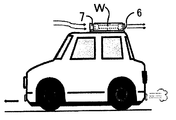
- FIGS. 2 to 3 are roof-mounted wind generators for automobiles, and FIG. 2 is a front view of the wind power generation unit. It is a side view of a wind power generation part. It is a top view of a wind power generation part. It is a top view which shows the cross-sectional shape of the blade
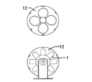
- 6 to 8 are front bonnet or rear trunk built-in types, and FIG. 6 is a front view of the wind power generator. It is a side view of a wind power generator. It is a rear view of a wind power generator. 9 to 11 show a fan-like windmill, and FIG.
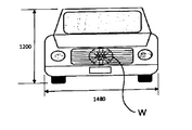
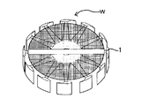
- FIG. 9 is a front view of the wind power generator. It is a right view of a wind power generator. It is a rear view of a wind power generator. 12 to 15 are side views showing a method of mounting the windmill on the automobile, and FIG. 12 is a type of mounting on the roof. It is a type that drives the windmill with the running wind coming into the engine room. It is a type that drives a windmill mounted in the trunk. This type is equipped with a windmill at the front edge of the roof. It is a front view which mounted the electric fan-shaped windmill in the bonnet of the motor vehicle. It is a perspective view of the windmill which has a ladle-like blade
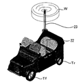
- FIG. 1 is a perspective view of an automobile that can generate wind power even when stopped.
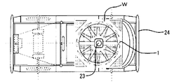
- FIG. It is a top view of the car which can generate wind power even when it is stopped.
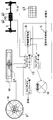
- FIG. 1 is a block diagram showing the whole aspect of the present invention.
- Each windmill W is rotated by the traveling wind received before the automobile travels to drive the generators g1 and g2 to charge the battery B.
- the electric power is output, the motor M of the automobile is operated, and the automobile is driven.
- the drive shaft generators G1 and G2 are attached to the drive shaft a of the front wheel or the rear wheel, and the generated electric power is charged to the battery B via the control device and the control device.
- the electric power generated by the solar battery panel E and the natural wind turbine when stopped is also charged to the battery B through the control device so that it can be generated and charged even when the vehicle is stopped.
- S is an emergency charger
- C is a control device
- in an inverter. Needless to say, all these devices are installed in automobiles.
- FIG. 2 to 4 are roof-mounted types, FIG. 2 is a front view, FIG. 3 is a side view, and FIG. 4 is a plan view.
- W is a windmill, and blades 1 are provided on the circumference, and a generator G is disposed inside. Therefore, when the windmill W rotates, the generator G rotates to generate power.
- a mounting plate 3 welded to a wind turbine or generator bearing 2 is mounted on a roof of the vehicle via a vibration-proof rubber 4. These devices are covered with a safety cover 5 and air is exhausted through the mesh on the upper surface, but there is also an exhaust port 6 at the rear, and the traveling wind is taken in from the inflow port 7 on the front surface. Rotate the windmill.
- FIG. 5 is a plan view showing the shape of the blade 1 of the windmill, and the shape of each blade 1 is concavely curved so that it can easily rotate by capturing the incoming wind.
- Such blades 1 are arranged radially at regular intervals. Now, assuming that the car is traveling leftward in the figure, winds come from the left to the right, and the windmill W receives both the tailwind and headwind, but the blades 1 are concavely curved. Only the upper half receives the tailwind effectively and rotates clockwise. However, since the lower half of the figure receives the head wind, rotation is suppressed. Therefore, in the present invention, only the lower half is closed by the baffle plate 13 so that the head wind cannot reach the blades 1 of the windmill W.
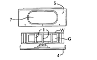
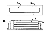
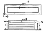
- FIG. 6 to 8 are front bonnet or rear trunk built-in types, FIG. 6 is a front view, FIG. 7 is a side view, and FIG. 8 is a rear view.
- W is a windmill, is a sirocco fan shape provided with strip-like blades 8 horizontally, and has a generator G on the side. As shown in FIG. 7, the cross-sectional shape of each blade 1... Is concavely curved so that it can easily rotate by capturing the wind.
- the sirocco fan-like windmill W and the generator G are covered with a cover 9, and traveling wind flows from the opening on the front surface of the cover. After the windmill W is rotated, it is discharged from the rearward discharge port 6.
- FIG. 9 to 11 show a fan-like windmill, which is mounted in the front front as shown in FIG.
- the windmill W includes a windmill W provided with blades 1... And a generator G mounted on a horizontal axis and covered with a safety protection cover 11.
- This safety protection cover 11 is fixed to a cover fixing plate 12 shown in FIG.
- FIG. 12 to 15 are side views showing a method of mounting the windmill on the automobile.
- FIG. 12 shows a type that is mounted on the roof, and the windmill W is driven by the traveling wind that arrives on the roof. After driving the windmill W, the air is exhausted onto the roof as it is.
- FIG. 13 shows a type in which a wind turbine W mounted in a bonnet is driven by traveling wind coming into the engine room. After driving the windmill W, the air is exhausted onto the road.
- FIG. 14 shows a case where the windmill W mounted in the trunk is driven, and the traveling wind coming on the roof and in front of the engine room is captured and guided to the windmill by the bellows. After the windmill W rotates, it is exhausted backward.
- FIG. 12 shows a type that is mounted on the roof, and the windmill W is driven by the traveling wind that arrives on the roof. After driving the windmill W, the air is exhausted onto the roof as it is.
- FIG. 13 shows a type in which a wind turbine W mounted in
- 15 is a type in which a windmill W is mounted on the front end of the roof, and the front end of the roof where both the traveling wind coming along the upper surface of the windshield f of the automobile and the traveling wind coming from the front on the upper surface of the roof enter.
- a windmill W is installed. These traveling winds can obtain large electric power because the wind force is hardly attenuated.
- the type of wind turbine in the present invention is free, and in addition to the horizontal axis type, a configuration in which the blades 1... Having a planar shape as shown in FIG. 171 are circumferentially arranged on the outer end of the radial arm is also possible. .
- the installation location is selected according to the windmill, but the windmill in the trunk as shown in FIG. 14 can be guided by a bellows or a duct.
- the fan-shaped windmill can be installed in the hood as shown in FIG.
- the electric vehicle equipped with the traveling wind power generator of the present invention can also obtain the following advantages.
- the wind flows relatively backward as a natural phenomenon and a wind velocity is generated. Therefore, by rotating the wind turbine of the traveling wind power generator using the wind velocity flowing behind it, it is integrated with the wind turbine. Since the generator is rotated at the same time, a rotating motion of the generator is generated to generate electric power, and the electric power is charged while automatically running on a dedicated storage battery already installed in the vehicle. Is possible. Therefore, it is possible to eliminate the anxiety that the vehicle cannot run due to the battery running out, and to enjoy stable driving and safe driving. However, the battery is charged with some electric power in advance, and electric power that can travel the minimum distance is ensured.
- the traveling wind power generator installed in the electric vehicle equipped with the traveling wind power generator of the present invention is born from the development technology of the wind turbine of the vertical axis type wind power generator, the generator, and the control system device, and is small and light. Because it can be attached and detached freely, it can be retrofitted to all electric vehicles.
- This electric vehicle equipped with a wind power generator is a dangerous bicycle or motorcycle that runs around in the living environment of developing countries where narrow streets in the city are the basis of life, and accidents frequently occur.
- a wind power generator In order to maintain a safe and rational living environment in the area, it is possible to design a compact size that is thin and long enough to fit the width of a bicycle or motorcycle, etc. You can regain the natural living environment of a clean alley that is free from noise and exhaust gas.
- a small electric vehicle equipped with this traveling wind power generator is installed on the front in the front of a wide-width vehicle that can accommodate multiple passengers. It is possible to develop a method of rotating the generator by applying wind velocity to the machine installed in the rear trunk via a nozzle, and in the case of a two-seater vehicle type with a narrow vehicle width, It is possible to select a plurality of types such as a method to be mounted on the ceiling, and because it is detachable, it can be used not only when traveling but also in all directions.
- One of the further features of the small electric vehicle equipped with this traveling wind power generator is that it automatically operates on a dedicated storage battery that is installed in advance by simply operating the traveling wind power generator using the wind velocity generated when traveling. Depending on the situation, charging from ordinary power is not necessary, and it has the advantage of being able to generate and store electricity with wind power even when stopped, in addition to fuel efficiency, in line with the Paris Agreement with zero pollution, It is an ideal car.
- Table 1 shows numerically the test results of running at different speeds for the small electric vehicle equipped with this traveling wind power generator.
- Table 2 shows specific numerical values for the apparatus used in this test.
- Table 3 shows specifications of drive system equipment mounted on the automobile.
- Table 4 lists the specifications of the wind turbine for the traveling wind generator.
- this traveling wind power generation type electric vehicle combines the rotation of the generator using the wind velocity generated when traveling with the power of the generator combined with the rotational driving force of the traveling and rotating wheels.
- Electric vehicle that can run while the remaining amount of storage battery can maintain a certain standard value because it is possible to automatically charge the electricity born from zero fuel consumption to the dedicated storage battery installed in advance.
- charging from ordinary power is not necessary, and there is also the advantage of not requiring any external power supply at all, the ideal car aiming for the Paris Agreement of zero fuel consumption, zero pollution, and real driving It is a wind-powered electric vehicle.
- FIG. 18 is a side view of the present invention applied to a track.
- the exterior of automobiles is made of 0.4mm to 0.8mm thick aluminum plate that is resistant to heat and is flexible.
- the effects of wind pressure and micro-vibration generated during driving, and external pressure In order to cope with the impact caused by the above, the surface of the aluminum plate used in the exterior part is formed with a concave groove to increase the strength by forming irregularities at intervals.
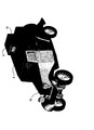
- the electric vehicle has an outer shape that is not a streamlined type that requires advanced technology, but is easy to process, which is a characteristic of an old vehicle as shown in FIG.
- a travel drive type generator G is attached to the drive shaft of the front wheel Tf.
- the rotational speed of the front wheel Tf is about 300 rpm, and the rotational speed of the rear wheel Tr is about 600 rpm.
- a system battery and a storage battery for storing generated electric power are incorporated.
- W is a traveling wind turbine and G is a generator.
- FIG. 19 is a plan view applied to a front and rear two-seater automobile, in which traveling drive type generators G and G are attached to a drive shaft between a wheel driving motor M and front wheels Tf and Tf.
- a storage battery or a control device is housed in the system box 15 as a system device.
- the left and right front wheels Tf, Tf connected to the electric motor M, which is the heart of the electric vehicle, by a shaft are driving units, which are the driving force of the electric vehicle. Since the driving load generators G and G attached to the shaft connecting the electric motor M and the front wheels or the left and right front wheels Tf and Tf, respectively, have a large rotational load value, they are little.
- the front wheel Tf is about 1.5 to 2.5 times larger than the rear wheel Tr in order to enable high-efficiency power generation with power consumption and support long-distance driving. Reduced load resistance.
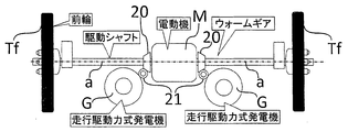
- FIG. 21 is a plan view showing the mounting structure of the travel drive generator G, in which the electric motor M is mounted in the middle of the shaft a for rotationally driving the left and right front wheels Tf, Tf. And it attaches to the same shaft a so that the left and right generators G and G can also be rotationally driven by this electric motor M.
- FIG. 22 shows another embodiment, in which the shafts a and a are inserted into the bevel gears 20 and 20, and the generators G and G are rotationally driven by the bevel gears 20 and 20 via the worms 21 and 21. ,Generate electricity.
- the gear means may use other types such as a spur gear instead of the bevel gear 20 and the worm 21.
- power may be generated on the rear wheels Tr and Tr side, or power may be generated using all of the front wheels Tf and Tf and the rear wheels Tr and Tr, and the battery may be charged. Good.
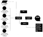
- FIG. 23 is a block diagram showing various power generation and charging systems in the electric vehicle according to the present invention.
- the outputs of the traveling wind hydrodynamic generator g1 and the traveling drive generator g2 are charged to the storage battery B via the controller c1.
- And consumed for driving the motors M and M are consumed for driving the motors M and M.
- the generated power of the solar battery panel E and the stopped wind power generator is also consumed for driving the motors M and M after charging the storage battery B via the controller c1.
- FIG. 24 is a perspective view of a device that can generate wind power and store it in the storage battery B even when it is stopped
- FIG. 25 is a plan view thereof.
- the hydraulic cylinder 22 is supported with the front wheel Tf, Tf and the rear wheel Tr, Tr being supported on the central portion of the vehicle body, and the piston 23 moves up and down.
- a windmill W is attached to the upper end of the piston 23.
- the planar shape is a shape in which the ladle-shaped blades 1 are attached to the outer ends of the radial arms.
- the windmill W rotates on the roof of the car to generate power. It is also possible, regardless of the type.
- the piston 23 When the car is stopped at a parking lot or the like, the piston 23 is extended to raise the windmill, and then the windmill W is rotated to drive the generator to generate power and charge the battery B.
- the windmill W is rotated to drive the generator to generate power and charge the battery B.
- the output of the traveling wind flow power generator g1 and the traveling driving force generators g2 and g2 is unstable because power is generated and charged while consuming electric power while the vehicle is running. Since wind power is generated after extending the windmill and raising the windmill, stable power generation is possible. Note that the wind turbine W in FIG. 26 can also generate wind power when stopped.
- the wind turbine W When it is desired to generate power even with the vertically moving wind turbine W during traveling, it is stable to lower the wind turbine W with the piston 23. Further, since the hydraulic cylinder 22 stands in the interior of the automobile, the wind turbine W may be attached using a carrier firmly attached to the automobile roof. At this time, the hydraulic cylinder 22 may be attached to the carrier.
- FIG. 26 a vertical axis type windmill W is mounted on the roof of an automobile, and a solar battery panel E provided on the roof above the windmill W is mounted, so that the sun can be stopped while driving (even during traveling).
- a solar battery panel E provided on the roof above the windmill W is mounted, so that the sun can be stopped while driving (even during traveling).
- the batteries E and E also generate power and charge the storage battery B.
- power generation by the solar cell E is impossible at night or in bad weather, power is generated and charged by the windmill W in FIGS.
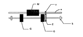
- FIG. 27 is a perspective view of the shaft-tuned generator, and the front wheels Tf, Tf or the rear wheels Tr, Tr are driven by a motor M connected by a shaft a.
- the motor M also generates power by rotating the generators G and G connected by the shaft a.
- FIG. 28 is a block diagram showing the entire system configuration of the power generation rechargeable electric vehicle according to the present invention.
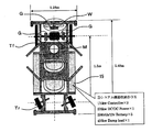
- FIG. 29 is a horizontal sectional view showing the basic configuration of the shaft-tuned generator according to the present invention.
- the power generation system of the shaft-tuned generator according to the present invention provides the same operation as that of an engine brake of an automobile using ordinary fossil fuel. That is, the electric motor M as a driving source of the traveling power generation type electric vehicle is a simple system in which the wheel rotates by depressing the accelerator pedal, and the driving of the wheel is released and stopped by releasing the accelerator pedal. However, the next operation when releasing the accelerator pedal for traveling is an operation of depressing the adjacent foot brake pedal.
- the shaft-tuned generator G is automatically shifted from the driving rotation of the electric motor M to the non-drive idling of only the wheel connected to the electric motor shaft a. , G rotates and is charged by generating electricity, so that the load of the shaft-tuned generators G and G supplements the role of the brake using the power generation load combined with the foot brake.
- the brake switch is turned on, and the rotational drive by the electric motor M shifts to the non-movable rotation of only the wheel connected to the shaft a.
- the gear z connected to the motor shaft a is automatically locked, and the shaft-tuned generators G and G start rotating and simultaneously generate and charge.
- the brake switch is turned off, and normal motor drive rotation is performed so that the vehicle can run.
- the configuration in FIG. 29 is an example, and any configuration that can switch the driving of the wheels by the motor to the rotation of the generator is effective because it can generate and replenish the power by rotating the shaft-tuned generator.
- power is generated by using the rotational driving force of the wheels that rotate according to the running of the automobile, and the generator is rotated by the windmill driven by the wind that flows in from the front, generating electric power
- the storage battery is charged, traveled by a motor driven by the output of the battery, and equipped with a control means for controlling them, it can travel while being wind-generated and charged by wind generated during travel.
- the auxiliary charge to the storage battery can be performed efficiently. Therefore, it is possible to eliminate the anxiety that the vehicle cannot run due to running out of battery or the like, and enjoy stable driving and safe driving.
Landscapes
- Engineering & Computer Science (AREA)
- Mechanical Engineering (AREA)
- Power Engineering (AREA)
- Life Sciences & Earth Sciences (AREA)
- Sustainable Development (AREA)
- Sustainable Energy (AREA)
- Chemical & Material Sciences (AREA)
- Combustion & Propulsion (AREA)
- General Engineering & Computer Science (AREA)
- Transportation (AREA)
- Wind Motors (AREA)
Abstract
L'invention vise, dans un véhicule électrique qui se déplace par l'entraînement d'un moteur à l'aide de la sortie d'une batterie installée, à permettre à la batterie d'être chargée par une génération d'énergie à l'aide de la force d'entraînement en rotation des roues. A cet effet, l'invention porte sur un générateur d'électricité synchronisé avec un arbre, lequel générateur est fixé à un arbre d'un moteur électrique qui amène un véhicule à se déplacer et est synchronisé avec la rotation du moteur électrique, et, par conséquent, naturellement, le générateur d'électricité synchronisé avec un arbre génère de l'électricité de manière fiable proportionnellement à la vitesse de rotation du moteur électrique en résultat du fonctionnement du véhicule, et l'électricité générée est utilisée pour charger une batterie de stockage installée. En outre, de l'électricité est générée à l'aide d'une turbine éolienne avant, d'une turbine éolienne de toit, ou analogue, à l'aide d'un écoulement d'air en déplacement qui est généré sans exception quand le véhicule se déplace, et l'électricité générée est utilisée pour charger la batterie, et il est par conséquent possible d'éliminer l'anxiété de l'apparition d'un accident, par lequel le véhicule ne peut pas fonctionner en raison de l'épuisement de la batterie, par exemple, et, par conséquent, un déplacement stable et une conduite stable peuvent être garantis.
Applications Claiming Priority (8)
| Application Number | Priority Date | Filing Date | Title |
|---|---|---|---|
| JP2016098582 | 2016-05-17 | ||
| JP2016-098582 | 2016-05-17 | ||
| JP2016-163960 | 2016-08-24 | ||
| JP2016163960 | 2016-08-24 | ||
| JP2016232917 | 2016-11-30 | ||
| JP2016-232917 | 2016-11-30 | ||
| JP2017096073A JP2018093699A (ja) | 2016-05-17 | 2017-05-12 | 走行充電式電気自動車 |
| JP2017-096073 | 2017-05-12 |
Publications (1)
| Publication Number | Publication Date |
|---|---|
| WO2017200018A1 true WO2017200018A1 (fr) | 2017-11-23 |
Family
ID=60325867
Family Applications (1)
| Application Number | Title | Priority Date | Filing Date |
|---|---|---|---|
| PCT/JP2017/018579 Ceased WO2017200018A1 (fr) | 2016-05-17 | 2017-05-17 | Véhicule électrique rechargeable générant de l'énergie |
Country Status (1)
| Country | Link |
|---|---|
| WO (1) | WO2017200018A1 (fr) |
Cited By (3)
| Publication number | Priority date | Publication date | Assignee | Title |
|---|---|---|---|---|
| CN109253053A (zh) * | 2018-11-06 | 2019-01-22 | 吴江 | 一种汽车风力发电装置与方法 |
| WO2024055053A1 (fr) * | 2022-09-15 | 2024-03-21 | Ac2T Research Gmbh | Panneau servant de convertisseur d'énergie éolienne et son utilisation |
| US11938833B2 (en) | 2022-08-22 | 2024-03-26 | Cooley Enterprises, LLC | Turbine powered electric or hybrid vehicle |
Citations (4)
| Publication number | Priority date | Publication date | Assignee | Title |
|---|---|---|---|---|
| JP2002359903A (ja) * | 2001-05-31 | 2002-12-13 | Nobuyuki Fujiyoshi | 車両搭載バッテリー充電用発電装置 |
| WO2009102625A1 (fr) * | 2008-02-11 | 2009-08-20 | John Friedmann | Véhicule électrique à énergie éolienne alimenté par batteries |
| JP2011226414A (ja) * | 2010-04-21 | 2011-11-10 | Bellsion:Kk | 自動乗物 |
| JP2014134100A (ja) * | 2013-01-08 | 2014-07-24 | Dyne:Kk | 車載用発電ユニット、及び車両 |
-
2017
- 2017-05-17 WO PCT/JP2017/018579 patent/WO2017200018A1/fr not_active Ceased
Patent Citations (4)
| Publication number | Priority date | Publication date | Assignee | Title |
|---|---|---|---|---|
| JP2002359903A (ja) * | 2001-05-31 | 2002-12-13 | Nobuyuki Fujiyoshi | 車両搭載バッテリー充電用発電装置 |
| WO2009102625A1 (fr) * | 2008-02-11 | 2009-08-20 | John Friedmann | Véhicule électrique à énergie éolienne alimenté par batteries |
| JP2011226414A (ja) * | 2010-04-21 | 2011-11-10 | Bellsion:Kk | 自動乗物 |
| JP2014134100A (ja) * | 2013-01-08 | 2014-07-24 | Dyne:Kk | 車載用発電ユニット、及び車両 |
Cited By (4)
| Publication number | Priority date | Publication date | Assignee | Title |
|---|---|---|---|---|
| CN109253053A (zh) * | 2018-11-06 | 2019-01-22 | 吴江 | 一种汽车风力发电装置与方法 |
| US11938833B2 (en) | 2022-08-22 | 2024-03-26 | Cooley Enterprises, LLC | Turbine powered electric or hybrid vehicle |
| US12485784B2 (en) | 2022-08-22 | 2025-12-02 | Cooley Enterprises, LLC | Turbine powered electric or hybrid vehicle |
| WO2024055053A1 (fr) * | 2022-09-15 | 2024-03-21 | Ac2T Research Gmbh | Panneau servant de convertisseur d'énergie éolienne et son utilisation |
Similar Documents
| Publication | Publication Date | Title |
|---|---|---|
| US7808121B1 (en) | Vehicle with electricity generating, braking wind turbine | |
| US9103317B2 (en) | Wind operated electricity generating system | |
| US6838782B2 (en) | Wind energy capturing device for moving vehicles | |
| US8710691B2 (en) | Wind driven generator for vehicles | |
| US6700215B2 (en) | Multiple installation varie gated generators for fossil fuel-and electric-powered vehicles | |
| US20020153178A1 (en) | Regenerative electric vehicle | |
| US5680032A (en) | Wind-powered battery charging system | |
| US8436485B1 (en) | Wind powered turbine motor for motor vehicles | |
| JP6571154B2 (ja) | 停止時風力発電充電式電気自動車 | |
| US20120085587A1 (en) | Wind Power for Electric Cars | |
| CN201592659U (zh) | 利用自然风能和太阳能的汽车 | |
| US20220355673A1 (en) | Vehicular wind turbine system | |
| US20210122249A1 (en) | Wind Based Electrical Generation System for Vehicles. | |
| US20090314567A1 (en) | Electric power tunnel apparatus | |
| JP2001073924A (ja) | 走行体用風洞式風車発電装置 | |
| WO2017200018A1 (fr) | Véhicule électrique rechargeable générant de l'énergie | |
| CN201484211U (zh) | 微型太阳能风能汽车 | |
| JP2011169297A (ja) | 風力発電電気自動車 | |
| CN105857093A (zh) | 汽车集风发电系统 | |
| US20220082088A1 (en) | Translationally movable wind power plant | |
| JP2000013906A (ja) | 風力風車二重対面式発電装置 | |
| RU121777U1 (ru) | Электромобиль с подзаряжаемой тяговой батареей от внешних источников энергии | |
| RU2480349C1 (ru) | Роторная ветроэнергетическая установка наземного транспортного средства | |
| JP2004132364A (ja) | 燃料が0の風力発電、電気自動車 | |
| CN103129338A (zh) | 净化空气的环保能源水陆两栖电动车 |
Legal Events
| Date | Code | Title | Description |
|---|---|---|---|
| NENP | Non-entry into the national phase |
Ref country code: DE |
|
| 121 | Ep: the epo has been informed by wipo that ep was designated in this application |
Ref document number: 17799442 Country of ref document: EP Kind code of ref document: A1 |
|
| 122 | Ep: pct application non-entry in european phase |
Ref document number: 17799442 Country of ref document: EP Kind code of ref document: A1 |