WO2017200227A1 - Procédé d'émission et de réception de données dans un système de communication sans fil, et dispositif pour sa prise en charge - Google Patents
Procédé d'émission et de réception de données dans un système de communication sans fil, et dispositif pour sa prise en charge Download PDFInfo
- Publication number
- WO2017200227A1 WO2017200227A1 PCT/KR2017/004590 KR2017004590W WO2017200227A1 WO 2017200227 A1 WO2017200227 A1 WO 2017200227A1 KR 2017004590 W KR2017004590 W KR 2017004590W WO 2017200227 A1 WO2017200227 A1 WO 2017200227A1
- Authority
- WO
- WIPO (PCT)
- Prior art keywords
- data
- layer
- transmitting
- cell
- transmission
- Prior art date
- Legal status (The legal status is an assumption and is not a legal conclusion. Google has not performed a legal analysis and makes no representation as to the accuracy of the status listed.)
- Ceased
Links
Images





Classifications
-
- H—ELECTRICITY
- H04—ELECTRIC COMMUNICATION TECHNIQUE
- H04W—WIRELESS COMMUNICATION NETWORKS
- H04W28/00—Network traffic management; Network resource management
- H04W28/02—Traffic management, e.g. flow control or congestion control
-
- H—ELECTRICITY
- H04—ELECTRIC COMMUNICATION TECHNIQUE
- H04W—WIRELESS COMMUNICATION NETWORKS
- H04W28/00—Network traffic management; Network resource management
- H04W28/02—Traffic management, e.g. flow control or congestion control
- H04W28/06—Optimizing the usage of the radio link, e.g. header compression, information sizing, discarding information
-
- H—ELECTRICITY
- H04—ELECTRIC COMMUNICATION TECHNIQUE
- H04W—WIRELESS COMMUNICATION NETWORKS
- H04W28/00—Network traffic management; Network resource management
- H04W28/02—Traffic management, e.g. flow control or congestion control
- H04W28/10—Flow control between communication endpoints
- H04W28/14—Flow control between communication endpoints using intermediate storage
Definitions
- the present invention relates to a method for transmitting and receiving data of a terminal in a wireless communication system, and more particularly, to a method for improving reliability of data transmission and reception and an apparatus for supporting the same.
- Mobile communication systems have been developed to provide voice services while ensuring user activity.
- the mobile communication system has expanded not only voice but also data service.As a result of the explosive increase in traffic, a shortage of resources and users are demanding higher speed services, a more advanced mobile communication system is required. have.
- An object of the present invention is to provide a method and apparatus for transmitting the same data in duplicate in order to increase the reliability of data transmission.
- Another object of the present invention is to provide a method and apparatus for transmitting the same data through a plurality of component carriers (CC) to which carrier aggregation (CA) is applied.
- CC component carriers
- CA carrier aggregation
- ID separate identifier
- Another object of the present invention is to provide a method and apparatus for processing duplicate data in a receiving apparatus when receiving duplicate data.
- Another object of the present invention is to provide a method and apparatus for recovering data received by a receiving apparatus when receiving duplicate data.
- the present invention provides a method and apparatus for transmitting and receiving data in a wireless communication system in order to solve the above problems.
- each of the transmission buffer and at least one transmission buffer replicated from the transmission buffer includes a cell identifier indicating a cell to which stored data is transmitted.
- the specific data and the at least one copy data are reconstructed through segmentation and concatenation functions.
- the number of the second layers is equal to the number of the specific data and the at least one copy data.
- the allocated resource amount is determined by a radio condition, a transmission power, a transmission resource, or a quality of service (QoS) of each of the plurality of radio bearers. .
- QoS quality of service
- the present invention may further include receiving, from the receiving apparatus, an Ack indicating the reception of the specific data or the at least one copy data.
- the present invention may further include instructing transmission of the specific data and the at least one copy data from the second layer to the first layer.
- the communication unit for transmitting and receiving a wireless signal with the outside; And a processor operatively coupled with the communication unit, wherein the processor reconfigures specific data in the second layer of the transmitting device based on a resource allocation transferred from the first layer of the transmitting device.
- the present invention has the effect of increasing the reliability of data transmission by transmitting the same data through a plurality of component carriers (CC) applied to the carrier aggregation (CA) or a plurality of cells applied to the dual connectivity (dual connectivity). have.
- CC component carriers
- CA carrier aggregation
- dual connectivity dual connectivity
- the present invention has the effect that the same data can be transmitted repeatedly by setting or resetting the logical path.
- the present invention has an effect that the terminal can identify the logical path for transmitting the duplicate data by setting a separate identifier (ID) to identify the logical path for the transmission of the duplicate data.
- ID separate identifier
- the present invention has the effect that the base station can identify whether the duplicated uplink data is transmitted by transmitting the indicator or index information indicating this through the control information, if the same uplink data is transmitted repeatedly.
- the present invention has the effect that it is possible to produce a plurality of the same data for providing the same service by creating a plurality of buffers containing duplicate data through the duplication of the buffer for storing data in a particular layer of the transmitting device.
- the present invention provides a specific layer for reconstructing the generated plurality of data according to the allocated resources by the number of the plurality of data, so that the same data can be individually reconstructed and transmitted on one or more component carriers. It works.
- the present invention when receiving a plurality of the same data, the present invention has the effect that it is possible to efficiently process a plurality of the same data transmitted by removing the remaining data except one of the plurality of the same data received at the receiving device .
- the present invention can reduce the waste of resources due to the redundant transmission of a plurality of the same data by sending a response message to the case that even one of a plurality of the same data is successfully received by sending a response message thereto It can be effective.
- FIG. 1 is a diagram illustrating an example of an EPS (Evolved Packet System) related to an LTE system to which the present invention can be applied.
- EPS Evolved Packet System
- FIG. 2 is a block diagram illustrating an example of a radio protocol architecture to which technical features of the present invention can be applied.
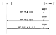
- FIG. 3 is a flowchart illustrating a process of establishing an RRC connection to which the present invention can be applied.
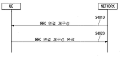
- FIG. 4 is a flowchart illustrating a RRC connection resetting process to which the present invention can be applied.
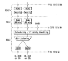
- 5 and 6 are diagrams illustrating an example of a layer 2 structure in carrier aggregation to which the present invention can be applied.
- FIG. 7 is a diagram illustrating an example of a component carrier and carrier aggregation in a wireless communication system to which the present invention can be applied.
- FIGS. 8 and 9 are diagrams illustrating an example of a structure and a network interface of dual connectivity to which the present invention can be applied.
- FIG. 10 is a flowchart illustrating an example of a method for transmitting the same data proposed in the present specification.
- 11 to 13 illustrate an example of a multiplexing method for transmitting the same data proposed in the present specification.
- FIG. 18 is a diagram illustrating an example of an internal block diagram of a wireless device to which the present invention can be applied.
- a base station has a meaning as a terminal node of a network that directly communicates with a terminal.
- the specific operation described as performed by the base station in this document may be performed by an upper node of the base station in some cases. That is, it is obvious that various operations performed for communication with a terminal in a network composed of a plurality of network nodes including a base station may be performed by the base station or other network nodes other than the base station.
- a 'base station (BS)' may be replaced by terms such as a fixed station, a Node B, an evolved-NodeB (eNB), a base transceiver system (BTS), an access point (AP), and the like. .
- a 'terminal' may be fixed or mobile, and may include a user equipment (UE), a mobile station (MS), a user terminal (UT), a mobile subscriber station (MSS), a subscriber station (SS), and an AMS ( Advanced Mobile Station (WT), Wireless Terminal (WT), Machine-Type Communication (MTC) Device, Machine-to-Machine (M2M) Device, Device-to-Device (D2D) Device, etc.
- UE user equipment
- MS mobile station
- UT user terminal
- MSS mobile subscriber station
- SS subscriber station
- AMS Advanced Mobile Station
- WT Wireless Terminal
- MTC Machine-Type Communication
- M2M Machine-to-Machine
- D2D Device-to-Device
- downlink means communication from a base station to a terminal
- uplink means communication from a terminal to a base station.
- a transmitter may be part of a base station, and a receiver may be part of a terminal.
- a transmitter may be part of a terminal and a receiver may be part of a base station.
- CDMA code division multiple access
- FDMA frequency division multiple access
- TDMA time division multiple access
- OFDMA orthogonal frequency division multiple access
- SC-FDMA single carrier frequency division multiple access
- GSM global system for mobile communications
- GPRS general packet radio service
- EDGE enhanced data rates for GSM evolution
- OFDMA may be implemented in a wireless technology such as IEEE 802.11 (Wi-Fi), IEEE 802.16 (WiMAX), IEEE 802-20, evolved UTRA (E-UTRA).
- UTRA is part of a universal mobile telecommunications system (UMTS).
- 3rd generation partnership project (3GPP) long term evolution (LTE) is a part of evolved UMTS (E-UMTS) using E-UTRA, and employs OFDMA in downlink and SC-FDMA in uplink.
- LTE-A (advanced) is the evolution of 3GPP LTE.
- Embodiments of the present invention may be supported by standard documents disclosed in at least one of IEEE 802, 3GPP, and 3GPP2, which are wireless access systems. That is, steps or parts which are not described to clearly reveal the technical spirit of the present invention among the embodiments of the present invention may be supported by the above documents. In addition, all terms disclosed in the present document can be described by the above standard document.
- EPS stands for Evolved Packet System and means a core network supporting a Long Term Evolution (LTE) network.
- LTE Long Term Evolution
- UMTS evolved network
- PDN Public Data Network
- APN Access Point Name: A name of an access point managed in a network, which is provided to a UE. That is, the name (string) of the PDN. Based on the name of the access point, the corresponding PDN for the transmission and reception of data is determined.
- Tunnel Endpoint Identifier An end point ID of a tunnel established between nodes in a network, and is set for each section in bearer units of each UE.
- MME Mobility Management Entity
- a session is a channel for data transmission.
- the unit may be a PDN, a bearer, or an IP flow unit.
- the difference between each unit can be divided into the entire unit network unit (APN or PDN unit), QoS classification unit (Bearer unit), and destination IP address unit as defined in 3GPP.
- APN unit network unit
- PDN unit QoS classification unit
- Bearer unit destination IP address unit as defined in 3GPP.
- EPS Bearer Logical path created between the UE and the gateway through which various kinds of traffic are transmitted and received.
- Default EPS Bear As a logical path for data transmission and reception basically created when the terminal accesses the network, it may be maintained until the terminal exits from the network.
- Dedicated EPS Bearer A logical path created when needed to provide additional services after the Default EPS Bearer is created.
- IP flow Various types of traffic transmitted and received through a logical path between a terminal and a gateway.
- Service Data Flow The IP flow or combination of multiple IP flows of user traffic classified by service type.
- PDN connection (connection) A connection from the terminal to the PDN, that is, the association (connection) of the terminal represented by the IP address with the PDN represented by the APN.
- UE Context The context information of the UE used to manage the UE in the network, that is, the context information consisting of UE id, mobility (current location, etc.), and attributes of the session (QoS, priority, etc.)
- FIG. 1 is a diagram illustrating an example of an EPS (Evolved Packet System) related to an LTE system to which the present invention can be applied.
- EPS Evolved Packet System
- the LTE system aims to provide seamless Internet Protocol connectivity between the user equipment (UE) and the packet data network (PDN) without interfering with the end user's use of the application on the go. .
- the LTE system completes the evolution of wireless access through the Evolved Universal Terrestrial Radio Access Network (E-UTRAN), which defines a radio protocol architecture between the user terminal and the base station, which is an Evolved Packet Core (EPC) network. It is also achieved through evolution in non-wireless terms by the inclusion of System Architecture Evolution (SAE).
- SAE System Architecture Evolution
- LTE and SAE include an Evolved Packet System (EPS).
- EPS Evolved Packet System
- the EPS uses the concept of EPS bearers to route IP traffic from the gateway to the user terminal in the PDN.
- a bearer is an IP packet flow having a specific Quality of Service (QoS) between the gateway and the user terminal.
- QoS Quality of Service
- E-UTRAN and EPC both set up and release bearers required by the application.
- EPC also called CN (core network)
- CN core network
- a node (logical or physical node) of an EPC of the SAE includes a mobility management entity (MME) 30, a PDN-GW or a PDN gateway (P-GW) 50, and an S-GW ( Serving Gateway (40), Policy and Charging Rules Function (PCRF) 60, Home Subscriber Server (HSS) 70, and the like.
- MME mobility management entity
- P-GW PDN gateway
- S-GW Serving Gateway
- PCRF Policy and Charging Rules Function
- HSS Home Subscriber Server
- the MME 30 is a control node that handles signaling between the UE and the CN.
- the protocol exchanged between the UE and the CN is known as the Non-Access Stratum (NAS) protocol.
- NAS Non-Access Stratum
- Examples of functions supported by the MME 30 include functions related to bearer management operated by the session management layer in the NAS protocol, including network setup, management, and release of bearers, network and It is manipulated by the connectivity layer or mobility management layer in the NAS protocol layer, including the establishment of connection and security between UEs.
- the S-GW 40 serves as a local mobility anchor for data bearers when the UE moves between base stations (eNodeBs). All user IP packets are sent via the S-GW 40.
- the S-GW 40 may also temporarily downlink data while the UE is in an idle state known as the ECM-IDLE state and the MME initiates paging of the UE to re-establish the bearer. Maintain information about bearers when buffering. It also serves as a mobility anchor for inter-working with other 3GPP technologies such as General Packet Radio Service (GRPS) and Universal Mobile Telecommunications System (UMTS).
- GRPS General Packet Radio Service
- UMTS Universal Mobile Telecommunications System
- the P-GW 50 performs IP address assignment for the UE and performs flow-based charging in accordance with QoS enforcement and rules from the PCRF 60.
- the P-GW 50 performs QoS enforcement for GBR bearers (Guaranteed Bit Rate (GBR) bearers). It also serves as a mobility anchor for interworking with non-3GPP technologies such as CDMA2000 and WiMAX networks.
- GBR bearers Guard Bit Rate (GBR) bearers
- the PCRF 60 performs policy control decision-making and performs flow-based charging.
- the HSS 70 is also called a home location register (HLR) and includes SAE subscription data including information on EPS-subscribed QoS profiles and access control for roaming. It also includes information about the PDN that the user accesses. This information may be maintained in the form of an Access Point Name (APN), which is a Domain Name system (DNS) -based label that identifies the PDN address that represents the access point or subscribed IP address for the PDN.
- API Access Point Name
- DNS Domain Name system
- various interfaces such as S1-U, S1-MME, S5 / S8, S11, S6a, Gx, Rx, and SG may be defined between EPS network elements.
- Mobility Management is a procedure to reduce overhead on the E-UTRAN and processing at the UE.
- MME mobility management
- the UE can inform the network about the new location whenever it leaves the current tracking area (TA) so that the network can contact the UE in the ECM-IDLE state.
- This procedure may be called “Tracking Area Update”, which may be called “Routing Area Update” in universal terrestrial radio access network (UTRAN) or GSM EDGE Radio Access Network (GERAN) system.
- the MME performs the function of tracking the user's location while the UE is in the ECM-IDLE state.
- the MME transmits a paging message to all base stations (eNodeBs) on the tracking area (TA) where the UE is registered.
- eNodeBs base stations
- TA tracking area
- the base station then begins paging for the UE over a radio interface.
- a procedure for causing the state of the UE to transition to the ECM-CONNECTED state is performed.
- This procedure can be called a “Service Request Procedure”. Accordingly, information related to the UE is generated in the E-UTRAN, and all bearers are re-established.
- the MME is responsible for resetting the radio bearer and updating the UE context on the base station.
- a mobility management (MM) backoff timer may be further used.
- the UE may transmit a tracking area update (TAU) to update the TA, and the MME may reject the TAU request due to core network congestion, in which case the MM backoff timer You can provide a time value.
- the UE may activate the MM backoff timer.
- TAU tracking area update
- FIG. 2 is a block diagram illustrating an example of a radio protocol architecture to which technical features of the present invention can be applied.
- FIG. 2A illustrates an example of a radio protocol architecture for a user plane
- FIG. 4B illustrates a radio protocol architecture for a control plane.
- the user plane is a protocol stack for user data transmission
- the control plane is a protocol stack for control signal transmission.
- a physical layer (PHY) layer provides an information transfer service to a higher layer using a physical channel.
- the physical layer is connected to a medium access control (MAC) layer, which is an upper layer, through a transport channel. Data is moved between the MAC layer and the physical layer through the transport channel. Transport channels are classified according to how and with what characteristics data is transmitted over the air interface.
- MAC medium access control
- the physical channel may be modulated by an orthogonal frequency division multiplexing (OFDM) scheme and utilizes time and frequency as radio resources.
- OFDM orthogonal frequency division multiplexing
- the function of the MAC layer is mapping between logical channels and transport channels and multiplexing / demultiplexing ('/') into transport blocks provided as physical channels on transport channels of MAC service data units (SDUs) belonging to the logical channels. Meaning includes both the concepts of 'or' and 'and').
- the MAC layer provides a service to a Radio Link Control (RLC) layer through a logical channel.
- RLC Radio Link Control
- Functions of the RLC layer include concatenation, segmentation, and reassembly of RLC SDUs.
- the RLC layer uses a transparent mode (TM), an unacknowledged mode (UM), and an acknowledged mode. It provides three modes of operation (AM).
- AM RLC provides error correction through an automatic repeat request (ARQ).
- the RRC (Radio Resource Control) layer is defined only in the control plane.
- the RRC layer is responsible for the control of logical channels, transport channels, and physical channels in connection with configuration, re-configuration, and release of radio bearers.
- RB means a logical path provided by the first layer (PHY layer) and the second layer (MAC layer, RLC layer, PDCP layer) for data transmission between the terminal and the network.
- PDCP Packet Data Convergence Protocol
- Functions of the Packet Data Convergence Protocol (PDCP) layer in the user plane include delivery of user data, header compression, and ciphering.
- the functionality of the Packet Data Convergence Protocol (PDCP) layer in the control plane includes the transfer of control plane data and encryption / integrity protection.
- the establishment of the RB means a process of defining characteristics of a radio protocol layer and a channel to provide a specific service, and setting each specific parameter and operation method.
- RB can be further divided into SRB (Signaling RB) and DRB (Data RB).
- SRB is used as a path for transmitting RRC messages in the control plane
- DRB is used as a path for transmitting user data in the user plane.
- the UE If an RRC connection is established between the RRC layer of the UE and the RRC layer of the E-UTRAN, the UE is in an RRC connected state, otherwise it is in an RRC idle state.
- the downlink transmission channel for transmitting data from the network to the UE includes a BCH (Broadcast Channel) for transmitting system information and a downlink shared channel (SCH) for transmitting user traffic or control messages.
- Traffic or control messages of a downlink multicast or broadcast service may be transmitted through a downlink SCH or may be transmitted through a separate downlink multicast channel (MCH).
- the uplink transport channel for transmitting data from the terminal to the network includes a random access channel (RACH) for transmitting an initial control message and an uplink shared channel (SCH) for transmitting user traffic or control messages.
- RACH random access channel
- SCH uplink shared channel
- BCCH broadcast control channel
- PCCH paging control channel
- CCCH common control channel
- MCCH multicast control channel
- MTCH multicast traffic
- the physical channel is composed of several OFDM symbols in the time domain and several sub-carriers in the frequency domain.
- One sub-frame consists of a plurality of OFDM symbols in the time domain.
- the RB is a resource allocation unit and includes a plurality of OFDM symbols and a plurality of subcarriers.
- each subframe may use specific subcarriers of specific OFDM symbols (eg, the first OFDM symbol) of the corresponding subframe for the physical downlink control channel (PDCCH), that is, the L1 / L2 control channel.
- Transmission Time Interval is a unit time of subframe transmission.
- FIG. 3 is a flowchart illustrating a process of establishing an RRC connection to which the present invention can be applied.
- the terminal sends an RRC connection request message to the network requesting an RRC connection (S3010).
- the network sends an RRC connection setup message in response to the RRC connection request (S3020). After receiving the RRC connection configuration message, the terminal enters the RRC connection mode.
- the UE sends an RRC Connection Setup Complete message used to confirm successful completion of RRC connection establishment to the network (S3030).
- FIG. 4 is a flowchart illustrating a RRC connection resetting process to which the present invention can be applied.
- RRC connection reconfiguration is used to modify an RRC connection. It is used to establish / modify / release RBs, perform handovers, and set up / modify / release measurements.
- the network sends an RRC connection reconfiguration message for modifying the RRC connection to the terminal (S4010).
- the terminal sends an RRC connection reconfiguration complete message used to confirm successful completion of the RRC connection reconfiguration to the network (S4020).
- the communication environment considered in the embodiments of the present invention includes both multi-carrier support environments.
- the multicarrier system or carrier aggregation (CA) system used in the present invention is one or more having a bandwidth smaller than the target band when configuring the target broadband to support the broadband
- the multi-carrier means the aggregation of carriers (or carrier aggregation), wherein the aggregation of carriers means not only merging between contiguous carriers but also merging between non-contiguous carriers.
- the number of component carriers aggregated between downlink and uplink may be set differently.
- the case where the number of downlink component carriers (hereinafter referred to as 'DL CC') and the number of uplink component carriers (hereinafter referred to as 'UL CC') is the same is called symmetric aggregation. This is called asymmetric aggregation.
- carrier aggregation may be used interchangeably with terms such as carrier aggregation, bandwidth aggregation, spectrum aggregation, and the like.
- Carrier aggregation in which two or more component carriers are combined, aims to support up to 100 MHz bandwidth in an LTE-A system.
- the bandwidth of the combining carrier may be limited to the bandwidth used by the existing system to maintain backward compatibility with the existing IMT system.
- the existing 3GPP LTE system supports ⁇ 1.4, 3, 5, 10, 15, 20 ⁇ MHz bandwidth
- the 3GPP LTE-advanced system i.e., LTE-A
- the carrier aggregation system used in the present invention may support carrier aggregation by defining a new bandwidth regardless of the bandwidth used in the existing system.
- the LTE-A system uses the concept of a cell to manage radio resources.
- the carrier aggregation environment described above may be referred to as a multiple cell environment.
- a cell is defined as a combination of a downlink resource (DL CC) and an uplink resource (UL CC), but the uplink resource is not an essential element. Accordingly, the cell may be configured with only downlink resources or with downlink resources and uplink resources.
- DL CC downlink resource
- UL CC uplink resource
- the cell may be configured with only downlink resources or with downlink resources and uplink resources.
- a specific UE When a specific UE has only one configured serving cell, it may have one DL CC and one UL CC, but when a specific UE has two or more configured serving cells, as many DLs as the number of cells Has a CC and the number of UL CCs may be the same or less.
- the DL CC and the UL CC may be configured on the contrary. That is, when a specific UE has a plurality of configured serving cells, a carrier aggregation environment in which a UL CC has more than the number of DL CCs may be supported. That is, carrier aggregation may be understood as merging two or more cells, each having a different carrier frequency (center frequency of a cell).
- carrier aggregation may be understood as merging two or more cells, each having a different carrier frequency (center frequency of a cell).
- the term 'cell' should be distinguished from the 'cell' as an area covered by a generally used base station.
- Cells used in the LTE-A system include a primary cell (PCell: Primary Cell) and a secondary cell (SCell: Secondary Cell).
- PCell Primary Cell
- SCell Secondary Cell
- P cell and S cell may be used as a serving cell.
- the UE that is in the RRC_CONNECTED state but the carrier aggregation is not configured or does not support the carrier aggregation, there is only one serving cell composed of the PCell.
- one or more serving cells may exist, and the entire serving cell includes a PCell and one or more SCells.
- Serving cells may be configured through an RRC parameter.
- PhysCellId is a cell's physical layer identifier and has an integer value from 0 to 503.
- SCellIndex is a short identifier used to identify an SCell and has an integer value from 1 to 7.
- ServCellIndex is a short identifier used to identify a serving cell (P cell or S cell) and has an integer value from 0 to 7. A value of 0 is applied to the Pcell, and SCellIndex is pre-assigned to apply to the Scell. That is, a cell having the smallest cell ID (or cell index) in ServCellIndex becomes a P cell.
- the P cell refers to a cell operating on a primary frequency (or primary CC).
- the UE may be used to perform an initial connection establishment process or to perform a connection re-establishment process and may also refer to a cell indicated in a handover process.
- the P cell refers to a cell serving as a center of control-related communication among serving cells configured in a carrier aggregation environment. That is, the terminal may receive and transmit a PUCCH only in its own Pcell, and may use only the Pcell to acquire system information or change a monitoring procedure.
- the Evolved Universal Terrestrial Radio Access (E-UTRAN) uses a higher layer RRC Connection Reconfiguration message including mobility control information to a terminal supporting a carrier aggregation environment for a handover procedure. You can only change it.
- the S cell may refer to a cell operating on a secondary frequency (or, secondary CC). Only one PCell may be allocated to a specific UE, and one or more SCells may be allocated.
- the SCell is configurable after the RRC connection is established and can be used to provide additional radio resources.
- the E-UTRAN may provide all system information related to the operation of the related cell in the RRC_CONNECTED state through a dedicated signal.
- the change of the system information may be controlled by the release and addition of the related SCell, and at this time, an RRC connection reconfiguration message of a higher layer may be used.
- the E-UTRAN may perform dedicated signaling having different parameters for each terminal, rather than broadcasting in the related SCell.
- the E-UTRAN may configure a network including one or more Scells in addition to the Pcells initially configured in the connection establishment process.
- the Pcell and the SCell may operate as respective component carriers.
- the primary component carrier (PCC) may be used in the same sense as the PCell
- the secondary component carrier (SCC) may be used in the same sense as the SCell.
- 5 and 6 are diagrams illustrating an example of a layer 2 structure in carrier aggregation to which the present invention can be applied.
- FIG. 5 shows an example of a Layer 2 structure in carrier aggregation for downlink data transmission
- FIG. 6 shows a carrier aggregation for uplink data transmission.
- An example of a layer 2 structure of a is shown.
- the multi-carriers of the physical layer are only revealed in the MAC layer in order to require one HARQ entity in each serving cell.
- one transport block is generated for each TTI in each serving cell.
- Each transport block and its potential HARQ retransmissions are mapped to a single serving cell.
- FIG. 7 is a diagram illustrating an example of a component carrier and carrier aggregation in a wireless communication system to which the present invention can be applied.
- Component carriers include a DL CC and an UL CC.
- One component carrier may have a frequency range of 20 MHz.
- FIG. 7 (b) shows a carrier aggregation structure used in the LTE_A system.
- three component carriers having a frequency size of 20 MHz are combined.
- the number of DL CCs and UL CCs is not limited.
- the UE may simultaneously monitor three CCs, receive downlink signals / data, and transmit uplink signals / data.
- the network may allocate M (M ⁇ N) DL CCs to the UE.
- the UE may monitor only M limited DL CCs and receive a DL signal.
- the network may give L (L ⁇ M ⁇ N) DL CCs to allocate a main DL CC to the UE, in which case the UE must monitor the L DL CCs. This method can be equally applied to uplink transmission.
- the linkage between the carrier frequency (or DL CC) of the downlink resource and the carrier frequency (or UL CC) of the uplink resource may be indicated by a higher layer message or system information such as an RRC message.
- a combination of DL resources and UL resources may be configured by a linkage defined by SIB2 (System Information Block Type2).
- SIB2 System Information Block Type2
- the linkage may mean a mapping relationship between a DL CC on which a PDCCH carrying a UL grant is transmitted and a UL CC using the UL grant, and a DL CC (or UL CC) and HARQ ACK on which data for HARQ is transmitted. It may mean a mapping relationship between UL CCs (or DL CCs) through which a / NACK signal is transmitted.
- the E-UTRAN is provided by a scheduler with two separate RX / TX UEs in RRC_CONNECTED and a non-ideal backhaul via the X2 interface. It supports dual connectivity (DC) operation configured to use radio resources located in two eNBs connected through the PC.
- DC dual connectivity
- Dual connectivity can imply control and data separation.
- control signaling for mobility is provided through the macro cell at the same time that the high-speed data connection is provided through the small cell.
- ENBs associated with dual connectivity for a particular UE may assume two different roles. For example, as shown in FIGS. 8 and 9, one eNB may act as a MeNB or SeNB.
- the UE may be connected with one MeNB and one SeNB.
- the MeNB is an eNB that terminates at least one S1-MME in dual connectivity (DC)
- the SeNB is an eNB that provides additional radio resources for the UE, but is not a master eNB in dual connectivity.
- the DC configured with the CA means an operation mode of the UE in the RRC connection state, and is composed of a Master Cell Group and a Secondary Cell Group.
- cell group indicates a group of serving cells associated with a master eNB (MeNB) or a secondary eNB (SeNB) in dual connectivity.
- MeNB master eNB
- SeNB secondary eNB
- a “Master Cell Group (MCG)” is a group of serving cells associated with a MeNB and includes a primary cell (PCell) and optionally one or more secondary cells (SCells) in dual connectivity. .
- SCG Secondary Cell Group
- a cell should be distinguished from the “cell” as a general area covered by the eNB. That is, a cell represents a combination of downlink and optionally uplink resources.
- the link between the carrier frequency of the downlink resource (eg, the center frequency of the cell) and the carrier frequency of the uplink resource is indicated in system information transmitted from the downlink resources.
- the MCG bearer is a radio protocol located only in MeNB to use only MeNB resources in dual connectivity
- the SCG bearer is a radio protocol located only in SeNB to use SeNB resources in dual connectivity.
- split bearer is a radio protocol located in both MeNB and SeNB to use both MeNB and SeNB resources in dual connectivity.
- Future communication technologies such as 5G aim to build ultra-low latency systems with extremely short response times to meet various requirements as requirements for supporting various real-time application services increase.
- the low latency high reliability service requires high reliability by transmitting data packets in a short TTI.
- As a method for satisfying such high reliability there are transmission through time diversity and transmission through frequency diversity.
- the time diversity scheme refers to a scheme in which, when the transmitting side transmits the same data several times over a time axis on the time axis, a good transmission quality is obtained by resynthesizing the received data transmitted from the receiving side.
- CA Carrier Aggregation
- CC component carriers
- DC and CA technologies are implemented for the purpose of improving the throughput or traffic offloading of the UE, they are not suitable for low latency high reliability services. Therefore, in future communication systems, DC and CA technologies must be designed to increase data reliability as well as data throughput.
- the configuration of the data transmission unit of the LTE / LTE-A system described above is an implementation issue in the downlink, and follows the logical channel prioritization procedure in the MAC layer in the uplink.
- each cell is composed of data transmission units in the order of the data stored in the buffer
- the present invention provides a method of duplicating the same data in multiple cells / other carriers and a plurality of identical data, each including a separate transmission buffer for each cell, in the transmission buffer.
- Layer 2 of the terminal or the base station is composed of N sub layers.
- the terminal when transmitting and receiving uplink data, the terminal may be referred to as a transmitting device and the base station as a receiving device, and when transmitting and receiving downlink data, the terminal may be called as a receiving device and the base station may be called as a transmitting device. .
- FIG. 10 is a flowchart illustrating an example of a method for transmitting the same data proposed in the present specification.
- the transmitting apparatus when transmission of a plurality of redundant data through multiple cells / multicarriers is activated, the transmitting apparatus generates a plurality of identical data by copying one data, and generates a plurality of identical data in multiple cells. Or it may transmit to the receiving device through the multiple carriers.
- Duplicated data TX a function of transmitting a plurality of identical data through multiple cells or other carriers.
- the transmitter and the receiver set or reset a plurality of logical paths for transmitting and receiving a plurality of identical data in the process of setting or resetting an initial logical path (Data Radio Bearer: DRB), and set a plurality of logical paths
- DRB Data Radio Bearer
- a specific logical path identifier (DRB Identifier: ID) may be allocated to each (S10010).
- the base station transmits system information including the assigned specific logical path identifiers to the terminal which is the receiving device.
- the receiving device may recognize logical paths capable of transmitting a plurality of identical data through specific logical path identifiers transmitted from the transmitting device, and may transmit and receive a plurality of identical data through the corresponding logical paths.
- the transmitting device transmits an indication message including an indication indicating an logical path configured for transmission of a plurality of identical data.
- the receiving device may recognize whether the set logical path is a logical path set for the transmission of the same data through the transmitted indication message, and if the set logical path is the logical path set for the transmission of the same data, It is possible to transmit and receive a plurality of the same data through.
- the transmitting device may inform the receiving device whether the logical path established through the RRC message is a logical path set for the transmission of a plurality of the same data.
- the transmitting device transmits an RRC message to the receiving device that includes an identifier indicating a logical path established for transmission of a plurality of identical data.
- the receiving device may recognize whether the logical path established through the transmitted RRC message is a logical path set for the transmission of the same data, and if the logical path is the logical path set for the transmission of the same data, It is possible to transmit and receive a plurality of the same data through.
- the transmitter When data for providing a specific service (eg, URLLC service, etc.) requiring high reliability and low delay occurs, the transmitter generates the same plurality of data (S10020).
- a specific service eg, URLLC service, etc.
- RKC layer of system -A duplicates (or duplicates) a transmission buffer that stores the generated logical path or data generated by the number of multiple cells / multicarriers corresponding to the configured logical path to generate a plurality of identical data.
- the second sublayer transfers a plurality of pieces of the same data stored in each of the duplicated transmission buffers to the first sublayer of layer 2, which is a lower layer (eg, the MAC layer of the 3GPP LTE / LTE-A system).
- the second sublayer receives data from a specific layer (eg, a TCP / IP layer or a PDCP layer) through a logical path established for every TTI, and transmits the received data to a transmission buffer (the second sublayer). 1 buffer). At this time, the transmission buffer exists for each logical path established to provide each service.
- a specific layer eg, a TCP / IP layer or a PDCP layer
- the transmission buffer exists for each logical path established to provide each service.
- the buffer of the second sub layer may exist as follows.
- the eMBB DRB and the URLLC DRB represent a logical path for providing an eMBB service and a logical path for providing a URLLC service, respectively.
- the second sublayer overlaps the first transmission buffer of the logical path applying Duplicated data TX by the number of multi-cells / multicarriers associated with (or corresponding to) the logical path or logical path that applies the Duplicated data TX to transmit a plurality of identical data. (Or duplicate).
- At least one transmission buffer (second buffer) generated by copying from the first transmission buffer stores the same data as the first data stored in the first transmission buffer, respectively, and stores a cell / multicarrier to which the stored data is transmitted.
- An identifier eg, Cell ID
- Cell 1, Cell 2 For example, when two cells (Cell 1, Cell 2) for transmitting a plurality of identical data may be as follows.
- the second sublayer reconstructs the data stored in the transmission buffer through segmentation and concatenation according to the radio resource allocation received to the lower layer.
- the second sublayer may exist as many as the number of identical data, and each second sublayer may reconstruct each of the plurality of identical data stored in each transmission buffer.
- the radio resource allocation amount may be determined according to a radio condition, a transmission power, a transmission resource, a quality of service (QoS) of a logical path, and the like.
- QoS quality of service
- each reconstructed data by the second sublayers may be as follows.
- Data 1 ', Data 2' and Data 2 '' mean reconstructed data 1, data 2 and duplicated data 2.
- the second sublayers deliver the reconstructed data to the first sublayer (eg, the MAC layer) of Layer 2, which is a lower layer.
- the first sublayer eg, the MAC layer
- Layer 2 which is a lower layer.
- the plurality of sub-layers may be connected through a specific interface protocol (for example, Xd interface) that connects the transmitting apparatus supporting the transmission of a plurality of identical data. Some of the same data may be transmitted to the first layer of another transmitter.
- a specific interface protocol for example, Xd interface
- the first sublayer multiplexes a plurality of data received from the plurality of second sublayers, and delivers the multiplexed data to layer 1.
- the first sublayer receives and multiplexes a plurality of identical data for providing a specific service from the second sublayer every TTI, and the multiplexed plurality of identical data cells (or component carriers) corresponding to each logical path.
- step (S10030) the first sublayer receives and multiplexes a plurality of identical data for providing a specific service from the second sublayer every TTI, and the multiplexed plurality of identical data cells (or component carriers) corresponding to each logical path.
- the following three methods may exist for the first sublayer to multiplex the data.
- the first sublayer may multiplex data of different services transmitted through different logical paths into one data, and transmit one multiplexed data on the same cell (or component carrier) corresponding to the logical path. have.
- the first sublayer multiplexes data of different services transmitted through different logical paths into respective data, and transmits multiplexed multiplexed data on the same cell (or component carrier) corresponding to the logical path.
- data of a specific service may be preferentially transmitted according to the priority of the logical path.
- data of another service may not be transmitted in the same cell, and only data of a specific service may be transmitted through a logical path whose priority is set to infinity.
- the first sublayer may multiplex data of different services transmitted through different logical paths, and transmit the multiplexed data on different cells (or component carriers) corresponding to the logical paths.
- different cells may be different subbands (or component carriers) of the same cell.
- the transmitting device may stop the transmission of the plurality of identical data (S10040).
- the second sublayer of the transmitting apparatus is the second sublayer of the transmitting apparatus when the first sublayer of at least one of the first sublayers of the receiving apparatus successfully receives data of one of a plurality of the same data.
- an indicator indicating interruption of a plurality of identical data may be transmitted to an internal operation of the transmitting apparatus.
- an indicator indicating interruption of a plurality of identical data is transmitted in a control message through a specific interface between the second sublayer and the first sublayer.
- the first sublayer which has received an indicator indicating transmission interruption from the second sublayer, stops transmitting and / or retransmitting data.
- the transmitting apparatus can satisfy a requirement of a specific service, particularly a service requiring high reliability and low delay by duplicating a plurality of identical data by duplicating a transmission buffer in which data of a specific service is stored.
- 11 to 13 illustrate an example of a multiplexing method for transmitting the same data proposed in the present specification.
- 11 to 13 specifically illustrate a method of multiplexing data in the transmission apparatus described with reference to FIG. 10.
- the second sublayer for reconfiguring data for providing a service may exist as many as the number of data or the number of established logical paths, and transmission of the second sublayer for storing data.
- the number of buffers may be equal to the number of data.
- Data reconstructed by the second sublayer is multiplexed by the first sublayer.
- FIG. 11 illustrates an example of a method of multiplexing data of different services transmitted through different logical paths into one data and transmitting the multiplexed data on the same cell (or component carrier) corresponding to the logical path. Illustrated.
- data of an eMBB service and data of a URLLC service transmitted through different logical paths are multiplexed into one data and then transmitted on the same cell.
- the data for providing the eMBB service and the first data for providing the URLLC service are multiplexed into one data and transmitted on the cell 1 (CC1) as described below.
- the second data contained in the second transmission buffer replicated from the first transmission buffer including the first data is multiplexed and transmitted on cell 2 (CC2).
- FIG. 12 illustrates an example of a method of multiplexing data of different services transmitted through different logical paths into respective data, and transmitting the multiplexed multiple data on the same cell or the same component carrier corresponding to the logical path; do.
- data of an eMBB service and data of a URLLC service transmitted through different logical paths are multiplexed into respective data and then transmitted on the same cell or the same component carrier as follows.
- data for providing a specific service may be transmitted first.
- data of a URLLC service requiring low delay and high trust may be transmitted preferentially over data of an eMBB service.
- the transmitting device may transmit only data for providing the URLLC service on cell 1 (CC 1) as follows.
- Data copied from the first data to provide the URLLC service may be transmitted through another component carrier of the same cell, or may be transmitted through another cell as shown in FIG. 12.
- the duplicated data is multiplexed and transmitted on the cell 2 (CC 2) corresponding to the logical path.
- FIG. 13 illustrates an example of a method of multiplexing data of different services transmitted through different logical paths and transmitting the multiplexed data on different cells (or component carriers) corresponding to the logical paths.
- data of an eMBB service and data of a URLLC service transmitted through different logical paths are multiplexed into respective data and then transmitted on different subbands of different cells or the same cell as follows.
- Data 1 'from eMBB DRB Tx Buffer is multiplexed and transmitted on Cell 1 or Cell subband
- a receiver may receive and restore the same plurality of data through multiple cells or multiple carriers.
- the receiving device may receive a plurality of identical data transmitted from the transmitting device (S14010). At this time, a plurality of identical data is transmitted on one or more cells or component carriers corresponding to a logical path established for transmitting the plurality of identical data.
- the first sublayer of Layer 2 of the receiving device demultiplexes a plurality of received identical data (S14020), and delivers a plurality of demultiplexed identical data to a second sublayer.
- the first sublayer receives a plurality of identical data transmitted on multiple cells / multicarriers every TTI and performs demultiplexing.
- the first sublayer demultiplexes the transmitted data to provide respective services. It maps to the configured logical path and delivers it to the second sub-layer.
- data for providing an eMBB service is mapped to a logical path for providing an eMBB service and transferred to a second sublayer
- data for providing a URLLC service is mapped to a logical path for providing a URLLC service. And is delivered to the second sublayer.
- CC2 Component Carrier 2
- the first sublayer demultiplexes the transmitted data to provide respective services. It maps to the configured logical path and delivers it to the second sublayer.
- CC1 Component Carrier 1
- CC2 Component Carrier 2
- the first sublayer demultiplexes the transmitted data to each service. It maps to the logical path set up to provide the data to the second sub-layer.
- data transmitted on each component carrier is demultiplexed so that data for providing each service is mapped to a logical path for providing URLLC service and delivered to a second sub-layer.
- the second sublayer receives the demultiplexed data from the first sublayer and performs a radio link control function (S14030).
- the second sublayer receives demultiplexed data including the same plurality of data from the first sublayer through a logical path established for providing each service for every TTI, and performs a radio link control function.
- the second sublayer performs HARQ reordering and reassembly functions of segmented or concatenation data.
- the ARQ function for data recovery may be performed by determining whether the received data is lost according to the setting.
- the second sublayer transfers the same plurality of data to the third sublayer.
- the third sublayer restores the same plurality of received data (S14040).
- the second sublayer receives each of a plurality of pieces of identical data through each logical path established for each TTI and stores the same data in a reception buffer.
- the reception buffer exists only in one logical path connected to the TCP / IP layer regardless of the number of logical paths for transmitting a plurality of identical data.
- the second sublayer performs functions such as discarding received data, notification of interruption of transmission of the same data, or waiting for receiving the same data transmitted in the next TTI according to whether the same data is received. .
- the second sublayer when the second sublayer successfully receives all data transmitted on a cell or component carrier corresponding to a logical path set for transmission of the same plurality of data, the second sublayer removes the same data except for one data.
- the second sublayer When the second sublayer receives at least one of a plurality of the same data, the second sublayer notifies the first sublayer of the data reception interruption through an indication indicating the interruption of the reception of the plurality of the same data.
- the second sublayer may notify the first sublayer of the interruption of the reception of a plurality of the same data through the following methods.
- the indicator may be delivered through an internal operation of the receiving device.
- a control message including an indicator may be delivered through a specific interface (eg, Xd interface) between the two layers.
- the second sublayer waits to receive the same data that is transmitted in the next TTI.
- the second sub-layer transmits the restored data to a higher layer (eg, PDCP layer) or TCP / IP layer through a corresponding logical path.
- a higher layer eg, PDCP layer
- TCP / IP layer TCP / IP layer
- a plurality of identical data for providing a specific service can be received, and the data can be efficiently restored by performing a specific operation depending on whether all or some of the plurality of identical data are received.
- FIG. 18 is a diagram illustrating an example of an internal block diagram of a wireless device to which the present invention can be applied.
- the wireless device may be a base station and a UE, and the base station includes both a macro base station and a small base station.
- the base station 1810 and the UE 1820 include a communication unit (transmitter and receiver, an RF unit, 1813 and 1823), a processor 1811 and 1821, and a memory 1812 and 1822.
- the base station and the UE may further include an input unit and an output unit.
- the communication units 1813 and 1823, the processors 1811 and 1821, the input unit, the output unit, and the memory 1812 and 1822 are functionally connected to perform the method proposed in this specification.
- the communication unit transmitter / receiver unit or RF unit, 1813, 1823
- the communication unit receives the information generated from the PHY protocol (Physical Layer Protocol)
- the received information is transferred to the RF-Radio-Frequency Spectrum, filtered, and amplified.
- the communication unit functions to move an RF signal (Radio Frequency Signal) received from the antenna to a band that can be processed by the PHY protocol and perform filtering.
- the communication unit may also include a switch function for switching the transmission and reception functions.
- Processors 1811 and 1821 implement the functions, processes, and / or methods proposed herein. Layers of the air interface protocol may be implemented by a processor.
- the processor may be represented by a controller, a controller, a control unit, a computer, or the like.
- the memories 1812 and 1822 are connected to a processor and store protocols or parameters for performing an uplink resource allocation method.
- Processors 1811 and 1821 may include application-specific integrated circuits (ASICs), other chipsets, logic circuits, and / or data processing devices.
- the memory may include read-only memory (ROM), random access memory (RAM), flash memory, memory card, storage medium and / or other storage device.
- the communication unit may include a baseband circuit for processing a wireless signal.
- the above-described technique may be implemented as a module (process, function, etc.) for performing the above-described function.
- the module may be stored in memory and executed by a processor.
- the memory may be internal or external to the processor and may be coupled to the processor by various well known means.
- the output unit (display unit or display unit) is controlled by a processor and outputs information output from the processor together with a key input signal generated at the key input unit and various information signals from the processor.
- Orientation-based device discovery method is not limited to the configuration and method of the embodiments described as described above, the embodiments are all or part of each of the embodiments is optional so that various modifications can be made It may be configured in combination.
- the direction-based device search method of the present specification may be implemented as processor-readable code in a processor-readable recording medium provided in a network device.
- the processor-readable recording medium includes all kinds of recording devices that store data that can be read by the processor. Examples of the processor-readable recording medium include ROM, RAM, CD-ROM, magnetic tape, floppy disk, optical data storage device, and the like, and may also be implemented in the form of a carrier wave such as transmission over the Internet. .
- the processor-readable recording medium can also be distributed over network coupled computer systems so that the processor-readable code is stored and executed in a distributed fashion.
- the RRC connection method has been described with reference to an example applied to the 3GPP LTE / LTE-A system.
- the RRC connection method may be applied to various wireless communication systems in addition to the 3GPP LTE / LTE-A system.
Landscapes
- Engineering & Computer Science (AREA)
- Computer Networks & Wireless Communication (AREA)
- Signal Processing (AREA)
- Mobile Radio Communication Systems (AREA)
Abstract
L'invention concerne un procédé et un dispositif destinés à émettre et à recevoir des données dans un système de communication sans fil. La présente invention concerne un procédé et un dispositif caractérisés en ce que: des données spécifiques sont reconfigurées dans une deuxième couche d'un dispositif d'émission d'après une quantité d'attribution de ressources émise à partir d'une première couche du dispositif d'émission; les données spécifiques reconfigurées sont stockées dans un tampon d'émission de la deuxième couche; au moins un élément de données de duplication est généré en utilisant les données spécifiques reconfigurées; et les données spécifiques reconfigurées et l'élément ou les éléments de données de duplication sont envoyés à un dispositif de réception dans une pluralité de cellules liées à une pluralité de supports sans fil, l'élément ou les éléments de données de duplication étant générés par la duplication du tampon d'émission selon le nombre de la pluralité de supports sans fil, et la pluralité de supports sans fil recevant pour instruction d'émettre des données de duplication au moyen d'un identifiant de support.
Applications Claiming Priority (2)
| Application Number | Priority Date | Filing Date | Title |
|---|---|---|---|
| US201662339065P | 2016-05-19 | 2016-05-19 | |
| US62/339,065 | 2016-05-19 |
Publications (1)
| Publication Number | Publication Date |
|---|---|
| WO2017200227A1 true WO2017200227A1 (fr) | 2017-11-23 |
Family
ID=60325995
Family Applications (1)
| Application Number | Title | Priority Date | Filing Date |
|---|---|---|---|
| PCT/KR2017/004590 Ceased WO2017200227A1 (fr) | 2016-05-19 | 2017-04-28 | Procédé d'émission et de réception de données dans un système de communication sans fil, et dispositif pour sa prise en charge |
Country Status (1)
| Country | Link |
|---|---|
| WO (1) | WO2017200227A1 (fr) |
Cited By (2)
| Publication number | Priority date | Publication date | Assignee | Title |
|---|---|---|---|---|
| WO2019156507A1 (fr) * | 2018-02-08 | 2019-08-15 | Lg Electronics Inc. | Procédé et appareil de notification de duplication de paquets |
| WO2019221421A1 (fr) * | 2018-05-18 | 2019-11-21 | Lg Electronics Inc. | Procédé et appareil permettant de transmettre des unités de données au moyen d'un équipement utilisateur dans un système de communication sans fil |
Citations (3)
| Publication number | Priority date | Publication date | Assignee | Title |
|---|---|---|---|---|
| US20130176988A1 (en) * | 2010-02-12 | 2013-07-11 | Interdigital Technology Corporation | Data split between multiple sites |
| KR20150018248A (ko) * | 2013-08-09 | 2015-02-23 | 주식회사 팬택 | 이중연결 시스템에서 멀티 플로우를 고려한 pdcp 재배열 방법 및 장치 |
| WO2016028563A1 (fr) * | 2014-08-19 | 2016-02-25 | Qualcomm Incorporated | Trafic multidiffusion à l'aide d'une connectivité multiple |
-
2017
- 2017-04-28 WO PCT/KR2017/004590 patent/WO2017200227A1/fr not_active Ceased
Patent Citations (3)
| Publication number | Priority date | Publication date | Assignee | Title |
|---|---|---|---|---|
| US20130176988A1 (en) * | 2010-02-12 | 2013-07-11 | Interdigital Technology Corporation | Data split between multiple sites |
| KR20150018248A (ko) * | 2013-08-09 | 2015-02-23 | 주식회사 팬택 | 이중연결 시스템에서 멀티 플로우를 고려한 pdcp 재배열 방법 및 장치 |
| WO2016028563A1 (fr) * | 2014-08-19 | 2016-02-25 | Qualcomm Incorporated | Trafic multidiffusion à l'aide d'une connectivité multiple |
Non-Patent Citations (2)
| Title |
|---|
| "5G User Plane Protocol Design", R2-162861, 3GPP TSG RAN WG2 MEETING #93BIS, 2 April 2016 (2016-04-02), Dubrovnik, Croatia, XP051082602, Retrieved from the Internet <URL:http://www.3gpp.org/flp/tsg_nran/WG2_KL2/TSGR2_93bis/Docs> * |
| "Uplink Bearer Split for LTE WLAN Radio Aggregation", R2-162789, 3GPP TSG RAN WG2 MEETING #93BIS, 1 April 2016 (2016-04-01), Dubrovnik, Croatia, XP051082227, Retrieved from the Internet <URL:http://www.3gpp.org/ftp/tsgran/WG2_RL2/TSGR2_93bis/Docs> * |
Cited By (3)
| Publication number | Priority date | Publication date | Assignee | Title |
|---|---|---|---|---|
| WO2019156507A1 (fr) * | 2018-02-08 | 2019-08-15 | Lg Electronics Inc. | Procédé et appareil de notification de duplication de paquets |
| WO2019221421A1 (fr) * | 2018-05-18 | 2019-11-21 | Lg Electronics Inc. | Procédé et appareil permettant de transmettre des unités de données au moyen d'un équipement utilisateur dans un système de communication sans fil |
| US11388768B2 (en) | 2018-05-18 | 2022-07-12 | Lg Electronics Inc. | Method and apparatus for performing a connection re-establishment and retransmission of packets by user equipment in wireless communication system |
Similar Documents
| Publication | Publication Date | Title |
|---|---|---|
| WO2017191952A1 (fr) | Procédé de transmission et de réception de données dans un système de communication sans fil et son dispositif de prise en charge | |
| WO2019160342A1 (fr) | Procédé et appareil prenant en charge une mobilité sans rach utilisant des faisceaux préalablement attribués dans un système de communication sans fil | |
| WO2020190005A1 (fr) | Procédé et appareil de mesure de la fréquence dans un système de communication sans fil | |
| WO2019194528A1 (fr) | Procédé et appareil pour l'exécution d'une transmission | |
| WO2018203622A1 (fr) | Procédé et dispositif de réception d'unité de données | |
| WO2015102334A1 (fr) | Procédé et appareil pour fournir un service gcse (group communication service enabler) dans un système de communication sans fil | |
| WO2014163287A1 (fr) | Procédé servant à rapporter un état de tampon et son dispositif de communication | |
| WO2018231007A1 (fr) | Procédé permettant de répondre à une demande et dispositif de réseau | |
| WO2018088812A1 (fr) | Procédé et équipement utilisateur de transfert intercellulaire | |
| WO2018079998A1 (fr) | Procédé de réalisation de transfert dans un système de communication sans fil, et dispositif associé | |
| WO2016153130A1 (fr) | Procédé et dispositif pour transmettre ou recevoir des données par un terminal dans un système de communication sans fil | |
| WO2014058242A1 (fr) | Procédé de traitement de recherche de mobile et procédé permettant de relayer des données de liaison descendante | |
| WO2017171451A1 (fr) | Procédé de transmission de données tamponnées dans un système de communications sans fil, et appareil associé | |
| EP3613236A1 (fr) | Procédé et appareil de signalisation de résultat de mesurage | |
| WO2017142171A1 (fr) | Procédé et terminal de création, modification, et libération de session dans un réseau de communications mobiles de prochaine génération | |
| WO2015137631A1 (fr) | Procédé pour la mise en œuvre de service de proximité, et dispositif utilisateur | |
| WO2017171201A1 (fr) | Procédé pour transmettre/recevoir des données dans un système de communication sans fil et dispositif prenant en charge ce dernier | |
| WO2016148357A1 (fr) | Procédé et appareil de transmission/réception de données pour terminal dans un système de communication sans fil | |
| WO2017171202A1 (fr) | Procédé d'émission/réception de données dans un système de communication sans fil et dispositif prenant en charge ce procédé | |
| WO2016140403A1 (fr) | Procédé et dispositif pour une connexion rrc d'un terminal dans un système de communication sans fil | |
| WO2014069927A1 (fr) | Procédé de surveillance de communications mtc | |
| WO2021133047A1 (fr) | Procédé par lequel un ue de communication de relais prend en charge efficacement un ue à distance lors d'une mise à jour de configuration | |
| WO2023204573A1 (fr) | Gestion d'identifiant de transaction dans des communications sans fil | |
| WO2017196015A1 (fr) | Procédé de transmission/réception de données dans un système de communication sans fil et dispositif le prenant en charge | |
| WO2017200227A1 (fr) | Procédé d'émission et de réception de données dans un système de communication sans fil, et dispositif pour sa prise en charge |
Legal Events
| Date | Code | Title | Description |
|---|---|---|---|
| NENP | Non-entry into the national phase |
Ref country code: DE |
|
| 121 | Ep: the epo has been informed by wipo that ep was designated in this application |
Ref document number: 17799585 Country of ref document: EP Kind code of ref document: A1 |
|
| 122 | Ep: pct application non-entry in european phase |
Ref document number: 17799585 Country of ref document: EP Kind code of ref document: A1 |