WO2017200235A1 - Dispositif et son procédé de fonctionnement - Google Patents
Dispositif et son procédé de fonctionnement Download PDFInfo
- Publication number
- WO2017200235A1 WO2017200235A1 PCT/KR2017/004844 KR2017004844W WO2017200235A1 WO 2017200235 A1 WO2017200235 A1 WO 2017200235A1 KR 2017004844 W KR2017004844 W KR 2017004844W WO 2017200235 A1 WO2017200235 A1 WO 2017200235A1
- Authority
- WO
- WIPO (PCT)
- Prior art keywords
- electronic device
- information
- light
- distance
- interaction
- Prior art date
- Legal status (The legal status is an assumption and is not a legal conclusion. Google has not performed a legal analysis and makes no representation as to the accuracy of the status listed.)
- Ceased
Links
Images


Classifications
-
- G—PHYSICS
- G06—COMPUTING OR CALCULATING; COUNTING
- G06F—ELECTRIC DIGITAL DATA PROCESSING
- G06F3/00—Input arrangements for transferring data to be processed into a form capable of being handled by the computer; Output arrangements for transferring data from processing unit to output unit, e.g. interface arrangements
- G06F3/01—Input arrangements or combined input and output arrangements for interaction between user and computer
- G06F3/03—Arrangements for converting the position or the displacement of a member into a coded form
- G06F3/041—Digitisers, e.g. for touch screens or touch pads, characterised by the transducing means
- G06F3/042—Digitisers, e.g. for touch screens or touch pads, characterised by the transducing means by opto-electronic means
- G06F3/0421—Digitisers, e.g. for touch screens or touch pads, characterised by the transducing means by opto-electronic means by interrupting or reflecting a light beam, e.g. optical touch-screen
- G06F3/0423—Digitisers, e.g. for touch screens or touch pads, characterised by the transducing means by opto-electronic means by interrupting or reflecting a light beam, e.g. optical touch-screen using sweeping light beams, e.g. using rotating or vibrating mirror
-
- G—PHYSICS
- G06—COMPUTING OR CALCULATING; COUNTING
- G06F—ELECTRIC DIGITAL DATA PROCESSING
- G06F3/00—Input arrangements for transferring data to be processed into a form capable of being handled by the computer; Output arrangements for transferring data from processing unit to output unit, e.g. interface arrangements
- G06F3/01—Input arrangements or combined input and output arrangements for interaction between user and computer
- G06F3/03—Arrangements for converting the position or the displacement of a member into a coded form
- G06F3/041—Digitisers, e.g. for touch screens or touch pads, characterised by the transducing means
- G06F3/042—Digitisers, e.g. for touch screens or touch pads, characterised by the transducing means by opto-electronic means
- G06F3/0421—Digitisers, e.g. for touch screens or touch pads, characterised by the transducing means by opto-electronic means by interrupting or reflecting a light beam, e.g. optical touch-screen
-
- G—PHYSICS
- G06—COMPUTING OR CALCULATING; COUNTING
- G06F—ELECTRIC DIGITAL DATA PROCESSING
- G06F3/00—Input arrangements for transferring data to be processed into a form capable of being handled by the computer; Output arrangements for transferring data from processing unit to output unit, e.g. interface arrangements
- G06F3/01—Input arrangements or combined input and output arrangements for interaction between user and computer
- G06F3/03—Arrangements for converting the position or the displacement of a member into a coded form
- G06F3/0304—Detection arrangements using opto-electronic means
-
- G—PHYSICS
- G06—COMPUTING OR CALCULATING; COUNTING
- G06F—ELECTRIC DIGITAL DATA PROCESSING
- G06F3/00—Input arrangements for transferring data to be processed into a form capable of being handled by the computer; Output arrangements for transferring data from processing unit to output unit, e.g. interface arrangements
- G06F3/01—Input arrangements or combined input and output arrangements for interaction between user and computer
- G06F3/017—Gesture based interaction, e.g. based on a set of recognized hand gestures
-
- G—PHYSICS
- G06—COMPUTING OR CALCULATING; COUNTING
- G06F—ELECTRIC DIGITAL DATA PROCESSING
- G06F3/00—Input arrangements for transferring data to be processed into a form capable of being handled by the computer; Output arrangements for transferring data from processing unit to output unit, e.g. interface arrangements
- G06F3/01—Input arrangements or combined input and output arrangements for interaction between user and computer
- G06F3/03—Arrangements for converting the position or the displacement of a member into a coded form
-
- G—PHYSICS
- G06—COMPUTING OR CALCULATING; COUNTING
- G06F—ELECTRIC DIGITAL DATA PROCESSING
- G06F3/00—Input arrangements for transferring data to be processed into a form capable of being handled by the computer; Output arrangements for transferring data from processing unit to output unit, e.g. interface arrangements
- G06F3/01—Input arrangements or combined input and output arrangements for interaction between user and computer
- G06F3/048—Interaction techniques based on graphical user interfaces [GUI]
- G06F3/0487—Interaction techniques based on graphical user interfaces [GUI] using specific features provided by the input device, e.g. functions controlled by the rotation of a mouse with dual sensing arrangements, or of the nature of the input device, e.g. tap gestures based on pressure sensed by a digitiser
- G06F3/0488—Interaction techniques based on graphical user interfaces [GUI] using specific features provided by the input device, e.g. functions controlled by the rotation of a mouse with dual sensing arrangements, or of the nature of the input device, e.g. tap gestures based on pressure sensed by a digitiser using a touch-screen or digitiser, e.g. input of commands through traced gestures
- G06F3/04883—Interaction techniques based on graphical user interfaces [GUI] using specific features provided by the input device, e.g. functions controlled by the rotation of a mouse with dual sensing arrangements, or of the nature of the input device, e.g. tap gestures based on pressure sensed by a digitiser using a touch-screen or digitiser, e.g. input of commands through traced gestures for inputting data by handwriting, e.g. gesture or text
Definitions
- One embodiment relates to an electronic device and a method, and more particularly, to an electronic device and a method of operating the electronic device for recognizing a user's gesture or touch operation.
- a smartphone or an electronic device may recognize a gesture through an installed camera, or receive a touch input through a touch sensitive display.
- Gesture recognition or touch input on the display of the electronic device requires the user to operate on the display of the limited electronic device.
- Various embodiments provide an electronic device and a method of operating the same, which can perform a gesture recognition or a touch input process in any space desired by a user and can reduce current consumption.
- the user may perform a gesture recognition or a process according to a touch input in any space desired by the user, thereby reducing current consumption.
- FIG. 1 is a reference diagram illustrating a concept of an electronic device according to an embodiment.
- FIG. 2 is a schematic block diagram of a system including an electronic device 100 according to an embodiment.
- FIG. 3 is a detailed block diagram of an example of an electronic device 100 according to an embodiment.
- FIG. 4 is a detailed block diagram of an example of an electronic device 100 according to an embodiment.
- FIG. 5 is a detailed block diagram of an example of an electronic device 100 according to an embodiment.
- FIG. 6 is a detailed block diagram of an example of an electronic device 100 according to an embodiment.
- FIG. 7 is a detailed block diagram of an optical module 130 included in an electronic device 100 according to an embodiment.
- 8A illustrates an example of an optical module in which an optical transmitter and a distance measuring sensor are arranged together, according to an exemplary embodiment.
- 8B illustrates an example of an optical module for arranging a light transmission unit in a mirror, according to an embodiment.
- 8C illustrates an example of an optical module that may be tilted by a mirror, according to an embodiment.
- 8D is a diagram for describing an operating principle of an optical module in which a mirror may tilt, according to an exemplary embodiment.
- FIG 9 illustrates an example in which the LED module is attached to four directions of the mirror, according to an exemplary embodiment.
- FIG. 10 is a flowchart illustrating a method of operating the electronic device 100 according to an exemplary embodiment.
- FIG. 12 is a flowchart illustrating a method of determining, by the electronic device 100, touch information and / or gesture information of an object based on distance information of the object, according to an exemplary embodiment.
- FIG. 13 is a flowchart illustrating a process of extracting interaction points according to an embodiment.
- 14 and 15 are reference diagrams for describing a method in which the electronic device 100 determines an interaction type.
- 16 is a reference diagram for explaining two-dimensional data and three-dimensional data.
- 17 is a reference diagram for explaining a method of extracting a main interaction point, according to an exemplary embodiment.
- FIG. 18 is a reference diagram for describing an operation when an interaction type is a virtual keyboard, according to an exemplary embodiment.
- 19 is a flowchart illustrating a method of operating an electronic device 100 according to an embodiment.
- 20 is a reference diagram for describing various methods of determining a range in which the electronic device 100 scans using a mirror.
- 21 is a reference diagram for describing a method of adaptively changing a range in which the electronic device 100 scans using a mirror.
- 22 is a flowchart illustrating a method of resolving a shadow area using two or more electronic devices according to an embodiment.
- FIG. 23 is a diagram for describing a method of eliminating a shadow area by using two or more electronic devices, according to an embodiment.
- FIG. 24 is a reference diagram for describing a method of allocating a gesture type for each touch location of a user or for each section in a scan range of the electronic device 100 and performing another control operation according to the gesture type.
- FIG. 25 is a flowchart illustrating a method of operating the electronic device 100 in a 3D sensing mode and a touch recognition mode.
- An electronic device is based on an optical module that irradiates light onto an object and detects a distance from the electronic device to the object by using light reflected from the object, and based on distance information from the detected object. And determine the touch information and / or gesture information of the object.
- an operation method of an electronic device may include: irradiating light onto an object and detecting a distance from the electronic device to the object by using light reflected from the object, and distance information from the detected object. And determining touch information and / or gesture information of the object based on the determination.
- a method of operating an electronic device in a computer-readable recording medium having recorded thereon a program for executing the method of operating the electronic device includes: irradiating light to an object and using the light reflected from the object from the electronic device. Detecting a distance to the object, and determining touch information and / or gesture information of the object based on the distance information to the detected object.
- first and second may be used to describe various components, but the components are not limited by the terms. The terms are only used to distinguish one component from another.
- first component may be referred to as the second component, and similarly, the second component may also be referred to as the first component.
- FIG. 1 is a reference diagram illustrating a concept of an electronic device according to an embodiment.
- an electronic device 100 may include a distance measuring device and a rotation mirror device to measure a distance to an object 10, and perform gesture recognition or touch input processing using the measured distance. have.
- the electronic device 100 may reflect the light from the light source using the rotation mirror device, and receive the light reflected from the object 10 through the distance measuring device.
- the distance measuring apparatus may measure the distance to the object 10 based on the light reflected from the object 10.
- the electronic device 100 may recognize a user's touch input or gesture based on the measured distance information to the object 10.
- the electronic device 100 Since the electronic device 100 performs a touch input or a gesture recognition based on the measured distance to the object 10, there is no restriction on the space in which the user operates.
- the electronic device 100 may be located in any space desired by the user, and the user may place the electronic device 100 in a desired space and perform a touch or gesture operation so that the electronic device 100 may recognize the user's touch input or gesture action. have.
- the electronic device 100 since the electronic device 100 uses a distance sensor instead of using a camera or a large capacitive screen for gesture recognition or touch input recognition, the electronic device 100 does not increase power consumption even when a user's operation is performed in a relatively large space. Can be.
- FIG. 2 is a schematic block diagram of a system including an electronic device 100 according to an embodiment.
- the system includes an electronic device 100 having an optical module, a network 200, and an external device 250.
- the electronic device 100 includes an optical module 130, a processor 110, and a communication module 120.
- the optical module 130 may measure the distance from the electronic device 100 to the object by irradiating light under the control of the processor 110 and receiving the light reflected from the object.
- the optical module 130 may include one or more light sources that emit light, a distance detection sensor that receives light reflected from the object, and detects a distance, and an element that changes a path of the transmitted and received light.
- the above light source may be integrally formed with the distance detection sensor or integrally with the element.
- the element may rotate in a transverse direction and / or in a direction different from the transverse direction.
- the communication module 120 may perform communication between the electronic device 100 and the external device 250 through the network 200 under the control of the processor 110.
- the processor 110 may control the overall operation of the electronic device 100 including the optical module 130 and the communication module 120.
- the processor 110 may perform touch input processing or gesture recognition processing based on the distance information from the optical module 130 to the measured object.
- the processor 110 may determine one or more interaction points based on distance information to the object.
- the processor 110 may include the one or more interaction points based on at least one of an interaction group determined based on distance information to the object, an interaction type of the determined interaction group, or an interaction type determined based on the distance information. Can decide.
- the processor 110 may determine a main interaction point associated with the one or more interaction points based on at least one of a direction and a speed at which the one or more interaction points move.
- the processor 110 may adjust a control factor for controlling the optical module based on environment information.
- the environment information may include at least one of a size of an area associated with an operation range of the object, a type of an application used with an electronic device, a type of an application associated with an operation of the object, and information associated with a surrounding environment of the electronic device. Can be.
- the processor 110 may obtain the environment information from at least one of a user input, an image acquisition sensor, an ambient environment detection sensor, and information detected by the optical module.
- the network 200 may include any network that enables communication between the electronic device 100 and the external device 250.
- the network 200 may include a wired network, a wireless network, or a local area network.
- the external device 250 may receive data from the electronic device 100 through the network 200 or transmit data to the electronic device 100.
- the external device 250 may receive distance information from the electronic device 100 to an object and perform gesture analysis using the information.
- FIG. 3 is a detailed block diagram of an example of an electronic device 100 according to an embodiment.
- the electronic device 100 includes a processor 110, a communication module 120, an optical module 130, a detection module 140, and a power management module 150.
- the communication module 120 may use Wi-Fi, Bluetooth, USB, and the like and use TCP / IP or sockets as a communication protocol.
- the optical module 130 transmits light and measures the distance to the object using the light reflected from the object.
- the detection module 140 may recognize a surrounding environment of the electronic device 100 or detect information about the surrounding environment.
- the detection module 140 may include a camera to detect information about a size of a space in which an object performs a touch or gesture, or detect a color of an object.
- the power management module 150 may use an internal battery or an external battery as a power source. Batteries may consist of cells obtained from natural energy, such as solar or solar cell cells.
- the processor 110 controls overall internal components of the electronic device 100 and may include an interaction pattern processing module 111, an electronic device factor adjusting module 112, and an environment recognition module 113.
- the interaction pattern processing module 111 may receive the distance information to the object from the optical module 130, and determine the type of interaction of the object by using a filter that grasps the interaction pattern stored in advance.
- the interaction type of the object may indicate whether there is one finger, two fingers, a pen, or a virtual keyboard.
- the electronic device factor adjusting module 112 may adjust a factor value of the optical module 130, for example, the rotation speed of the mirror, the tilt angle of the mirror, and the brightness of the light source.
- the environment recognition module 113 may recognize a surrounding environment of the electronic device 100.
- the surrounding environment of the electronic device 100 may include a size of a space where a gesture operation is performed, a size of a space where a touch operation is performed, whether a person is hitting a virtual keyboard, a light intensity of the surrounding environment, and the like.
- FIG. 4 is a detailed block diagram of an example of an electronic device 100 according to an embodiment.
- the electronic device 100 includes a communication module 120, an optical module 130, a detection module 140, and a power management module 150.
- the example illustrated in FIG. 4 is the same as the electronic device 100 illustrated in FIG. 3, but does not include the processor 110.
- the distance information from the optical module 130 to the received object is transmitted to the external device through the communication module 120, and the gesture analysis and touch analysis are performed using the distance information to the object received by the external device. Can be done.
- FIG. 5 is a detailed block diagram of an example of an electronic device 100 according to an embodiment.
- the electronic device 100 includes a communication module 120, an optical module 130, and a power management module 150.
- the electronic device 100 illustrated in FIG. 5 may receive information detected by the detection module 140 from the connected external device through the communication module 120.
- a separate external camera which may serve as the detection module 140 may be connected to the electronic device 100 and receive information through the external camera.
- FIG. 6 is a detailed block diagram of an example of an electronic device 100 according to an embodiment.
- the electronic device 100 may include one or more processors 110, a communication module 120, an optical module 130, a detection module 140, a power management module 150, a projection module 160, an input / output interface 170, an audio module 180, Memory 190 may be included.
- the processor 110 may control a plurality of hardware or software components connected to the processor 110 by operating an operating system or an application program, and may perform various data processing and operations including multimedia data.
- the processor 110 may be implemented with, for example, a system on chip (SoC).
- SoC system on chip
- the processor 110 may further include a graphic processing unit (GPU).
- the processor 110 may determine touch information and / or gesture information of the object based on distance information from the optical module 130 to the object.
- the communication module 120 may transmit / receive data in communication between other electronic devices connected to the electronic device 100 through a network, for example, another electronic device or a server.
- the communication module 120 may include a Wifi module 121, a BT module 122, and a radio frequency (RF) module 123.
- RF radio frequency
- the Wi-Fi module 121 and the BT module 122 may include, for example, a processor that processes data transmitted and received through a corresponding module.
- the Wifi module 121 or the BT module 122 is illustrated as separate blocks, but according to an embodiment, at least some (eg, two or more) of the Wifi module 121 and the BT module 122 may include one integrated chip ( IC) or IC package.
- IC integrated chip
- the processors corresponding to the Wifi module 121 and the BT module 122 may be implemented as one SoC.
- the RF module 123 may transmit and receive data, for example, an RF signal.
- the RF module 123 may include, for example, a transceiver, a power amplifier module (PAM), a frequency filter, a low noise amplifier (LNA), or the like.
- the RF module 123 may further include a component that transmits and receives electromagnetic waves in free space in wireless communication, for example, a conductor or a conductive wire.
- the Wifi module 121 and the BT module 122 are illustrated as sharing one RF module 123. However, according to an embodiment, at least one of the Wifi module 121 and the BT module 122 may be RF through separate RF modules. Transmission and reception of signals can be performed.
- the communication module 120 may transmit gesture information, touch information, or distance information to an object detected by the optical module 130 determined by the processor 110 to an external device.
- the optical module 130 may include a light source, a rotation mirror device, and a distance measuring device.
- the optical module 130 may irradiate light onto the object, receive light reflected from the object, and measure a distance from the object to the light.
- the optical module 160 will be described in detail with reference to FIGS. 8 to 9.
- the detection module 140 may measure a physical quantity or detect an operation state of the electronic device 100 to convert the measured or detected information into an electrical signal.
- the detection module 140 may include at least one of an image sensor 140A, a gyro sensor 140B, an acceleration sensor 140C, an ultrasonic sensor 140D, an infrared sensor 140E, a hall sensor 140F, a proximity sensor 140G, and an illumination sensor 140H.
- the detection module 140 may include, for example, an olfactory sensor (E-nose sensor, not shown), an EMG sensor (electromyography sensor, not shown), an EEG sensor (electroencephalogram sensor, not shown), an ECG sensor ( electrocardiogram sensors, not shown, iris sensors (not shown) or fingerprint sensors (not shown), pressure sensors (not shown) and the like.
- the detection module 140 may further include a control circuit for controlling at least one or more sensors belonging therein.
- the detection module 140 detects the surrounding environment of the electronic device 100, for example, the brightness of light or the color of an object or the size of a space where a gesture or a touch is made, using at least one sensor included therein. can do.
- the power management module 150 may manage power of the electronic device 100.
- the power management module 150 may include, for example, a power management integrated circuit (PMIC), a charger integrated circuit (ICC), or a battery or fuel gauge.
- PMIC power management integrated circuit
- ICC charger integrated circuit
- the PMIC may be mounted in, for example, an integrated circuit or an SoC semiconductor.
- Charging methods may be divided into wired and wireless.
- the charger IC may charge a battery and prevent overvoltage or overcurrent from flowing from a charger.
- the charger IC may include a charger IC capable of at least one of a wired charging method and a wireless charging method.
- the wireless charging module 152 may include a circuit capable of wireless charging, for example, a circuit such as a coil loop, a resonant circuit or a rectifier.
- the wireless charging method may include, for example, a magnetic resonance method and a magnetic induction method. Or electromagnetic wave method.
- the battery 151 may store or generate electricity, and supply power to the electronic device 100 using the stored or generated electricity.
- the battery 151 may include, for example, a rechargeable battery or a solar battery.
- the projection module 160 may include an illumination module and a projection module.
- the projection module may display an image by projecting light onto a screen. As the projection module projects light, there are DLP, LCOS, 3LCD, LCD, laser, and the like.
- the projection module 160 may project an image
- the optical module 130 may detect a user gesture in the projected image.
- the input / output interface 170 may include, for example, a high-definition multimedia interface (HDMI) 171 and a universal serial bus (USB) 172. Additionally or alternatively, the interface 170 may include, for example, a mobile high-definition link (MHL) interface, a secure digital (SD) card / multi-media card (MMC) interface, or an infrared data association (IrDA) compliant interface. can do.
- HDMI high-definition multimedia interface
- USB universal serial bus
- MHL mobile high-definition link
- SD secure digital
- MMC multi-media card
- IrDA infrared data association
- the audio module 180 bidirectionally converts a sound and an electrical signal.
- the audio module 180 may process sound information input or output through, for example, a speaker 181 or a microphone 182.
- the memory 190 may include an internal memory 191.
- the internal memory 191 may be, for example, a volatile memory (for example, a dynamic RAM (DRAM), a static RAM (SRAM), a synchronous dynamic RAM (SDRAM), etc.) or a non-volatile memory (for example).
- a volatile memory for example, a dynamic RAM (DRAM), a static RAM (SRAM), a synchronous dynamic RAM (SDRAM), etc.
- a non-volatile memory for example.
- OTPROM programmable ROM
- PROM programmable ROM
- EPROM erasable and programmable ROM
- EEPROM electrically erasable and programmable ROM
- mask ROM mask ROM
- flash ROM NAND flash memory
- NOR flash memory etc. It may include.
- the memory 190 may store various data, programs or applications for driving and controlling the electronic device 100 under the control of the processor.
- the memory 190 stores input / output signals or data corresponding to the driving of one or more processors 110, communication module 120, detection module 140, optical module 130, input / output interface 170, audio module 180, and power management module 150. Can be stored.
- Each of the above-described elements of the electronic device according to various embodiments may be formed of one or more components, and the name of the corresponding element may vary according to the type of the electronic device.
- An electronic device according to various embodiments of the present disclosure may be configured to include at least one of the above-described components, and some components may be omitted or further include other additional components.
- some of the components of the electronic device according to various embodiments of the present disclosure may be combined to form a single entity, thereby performing the same functions of the corresponding components before being combined.
- optical module 130 included in the electronic device 100 will be described in detail.
- the optical module 130 may include a light source, a light path changing element that changes a path of light from the light source and transmits the light to the object, receives light reflected from the object, and receives the light from the optical device based on the reflected light. And a distance detecting sensor for detecting a distance to the object, and a rotating element for rotating the light path changing element.
- a mirror, a lens, a prism, or the like may be used as the light path changing element.
- the distance detecting sensor for example, a TOF distance sensor may be used, but the present invention is not limited thereto, and any sensor may be used.
- the rotation element may include at least one of a rotation support for rotating the light path element in a lateral direction or a tilt support for rotating the light path element in a direction different from the lateral direction.
- Such an optical module 130 may itself be referred to as an optical device used for distance detection.
- an optical device used for distance detection by providing the element for changing the light path and the rotating element for rotating the light path changing element, it becomes possible to effectively detect the distance to the object without increasing the volume of the optical module.
- the optical module or the optical device according to the embodiment can be conveniently and effectively utilized in various fields.
- such an optical device may be mounted on a portable projection device and used together.
- such an optical device may be attached to a portion of a TV display to detect a user's touch or gesture with respect to a screen displayed on the TV.
- such an optical device may be mounted on a small drone and used with the drone.
- such an optical device may be mounted on glasses or the like that implement virtual reality and used together.
- FIG. 7 is a detailed block diagram of an optical module 130 included in an electronic device 100 according to an embodiment.
- the optical module 130 may include an optical transmitter 131, a distance sensor 132, a mirror 133, a rotation support 134, a gear 135, and a motor 136.
- the light transmitter 131 may transmit infrared light.
- the light transmitter 131 may use an LED module.
- the distance measuring sensor 132 may receive the light reflected through the mirror 133, including the light receiving unit, and measure the distance from the electronic device 100 to the object 10 by analyzing characteristics of the received light.
- the distance measuring sensor 132 may include a time of flight (TOF) distance sensor.
- TOF technology is a method of measuring the distance between a sensor and an object based on a time difference that is returned to the sensor after the signal is emitted to the object and reflected by the object.
- TOF technology is a method of measuring the distance between a sensor and an object based on a time difference that is returned to the sensor after the signal is emitted to the object and reflected by the object.
- Various types may be used as carriers for transmitting signals, and the most common forms are sound and light.
- the mirror 133 may reflect the light received from the light transmitter 131 and transmit the reflected light to the object 10. In this case, the light may be transmitted to a specific position according to the angle and the reflection angle of the mirror 133.
- the light transmitted as described above may be reflected by a specific object, that is, the object 10, and returned to the mirror 133 or may be lost.
- a prism or lens can be used as another element.
- the mirror 133 is rotated about 360 degrees by the motor 136 and the gear 135 and the rotation support 134 to detect the surrounding objects and obtain information about how far they are located.
- the mirror 133 may be variously rotated according to the angle at which the rotation support 134 rotates.
- the mirror 133 a material capable of reflecting light well through a CVD process may be used.
- Materials that can be used for the mirror can be gold (Au) or silver (Ag), for example.
- the rotation support 134 may be connected to the mirror 133 to rotate the mirror by a predetermined angle. For example, when the light scanning range is about 60 degrees and the rotation support 134 moves about 1 degree at a time, the rotation support 134 can scan about 60 degrees by moving about 60 times.
- the mirror 133, the rotation support 134, the gear 135, and the motor 136 may be miniaturized using MEMS (Micro Electro Mechanical Systems) technology to significantly reduce the volume of the product.
- MEMS Micro Electro Mechanical Systems
- the motor 136 may be implemented using a small, low power, low noise motor using a piezo-electric effect.
- the gears 135 may be changed up, down, left and right according to the motor 136.
- 8A illustrates an example of an optical module in which an optical transmitter and a distance measuring sensor are arranged together, according to an exemplary embodiment.
- the optical transmitter 131 and the distance measuring sensor 132 for receiving light are integrally formed.
- the light transmitted from the light transmitter 131 may be reflected to the mirror 133 and transmitted to the object.
- the light transmitted from the light transmitter 131 may be reflected to the mirror 133 and transmitted to the object, and some light may be lost or some light may be reflected to the mirror 133 and absorbed by the distance measuring sensor 132. Therefore, the light received by the distance measuring sensor 132 may include not only the light reflected from the object but also the light absorbed by the light from the light transmitting unit 131 reflected on the mirror 133. Since the absorbed light acts as noise, the distance measuring sensor 132 may act as an element that prevents accurate measurement when measuring the distance based on the light reflected from the object.
- 8B illustrates an example of an optical module for arranging a light transmission unit in a mirror, according to an embodiment.
- the optical transmitter 131 is arranged in the mirror 133 and integrally formed. As such, when the light transmitter 131 is disposed in the mirror 133, the light from the light transmitter 131 may be directly transmitted to the object by reducing the reflection of the light from the mirror 133. Can be absorbed. Therefore, since the distance measuring sensor 132 receives only the light reflected from the object, it is possible to ensure accuracy in the distance measurement.
- the light is scattered and refracted so that no matter how well the mirror reflects the light, the efficiency may not be 100%. Therefore, when the light transmitting unit 131 is arranged in the mirror 133, scattering or distortion of light may be reduced.
- the mirror can be rotated in accordance with the rotation of the rotational support, as well as the mirror can also be tilted.
- 8C illustrates an example of an optical module that may be tilted by a mirror, according to an embodiment.
- the mirror 133 further includes a tilt support 137 that performs longitudinal rotation on the rear surface of the mirror as well as a rotation support 134 that rotates in the lateral direction.
- the mirror 133 may scan the object in the left and right directions by rotating by the rotation support 134, and may also scan the object in the vertical direction by rotating the tilt support 137.
- the electronic device 100 may detect two-dimensional data about distance information to the object by scanning the mirror 133 in the left and right directions, and three-dimensional data about distance information to the object by scanning the mirror 133 in the left and right directions and up and down directions. Can be detected.
- the tilt support 137 may be attached to the rear surface of the mirror with an oblique line to scan the mirror 133 in an oblique direction to detect three-dimensional data.
- the dictionary direction means any direction between the longitudinal direction and the transverse direction.
- the tilt of the mirror may be finely adjusted by using a general motor to adjust up and down by using a general motor or by applying a piezo method to a material that changes shape.
- the height of the mirror can be adjusted in the vertical direction, allowing various three-dimensional data measurements. As such, it becomes possible to detect force touch or hovering motion through three-dimensional data scanning using a tilt or linear motor.
- 8D is a diagram for describing an operating principle of an optical module in which a mirror may tilt, according to an exemplary embodiment.
- the mirror 133 may be tilted in the longitudinal direction according to the rotation of the tilt support 137.
- the light transmitted from the light transmitter 131 is reflected by the mirror 133 to irradiate the position 810 of the object.
- the light reflected from the position 810 of the object and received by the distance measuring sensor 132 may indicate distance information up to the position 810 of the object.
- the mirror 133 is tilted at the second tilt angle, the light transmitted from the light transmitter 131 is reflected by the mirror 133 to irradiate the position 820 of the object. Therefore, the light reflected from the position 820 of the object and received by the distance measuring sensor 132 may represent distance information up to the position 820 of the object.
- the distance information of the object may be detected at a wider angle of view.
- the distance information of the finger may also be detected. Through this, not only a touch action but also a hovering action or a force touch action may be detected.
- FIG 9 illustrates an example in which the LED module is attached to four directions of the mirror, according to an exemplary embodiment.
- light transmission units 131 are arranged in four directions in the mirror 133.
- the structure illustrated in FIG. 9 may use a method of directly attaching the light transmitting unit 131 to the mirror 133 or a semiconductor processing technology.
- the method using the semiconductor processing technology may be a form of manufacturing a semiconductor or the like in a thin film form and directly making an LED thereon. Power is supplied through the semiconductor thin film and can be supplied through the support.
- an electric circuit may be configured to attach an LED module to four directions of the mirror 133 and to supply power to the LED through a conductive film, a material, or a chemical vapor deposition (CVD) process.
- Power supply can be received through a rotating support 134 that rotates the mirror.
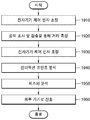
- FIG. 10 is a flowchart illustrating a method of operating the electronic device 100 according to an exemplary embodiment.
- the optical module 130 of the electronic device 100 may radiate light to an object and detect a distance from the electronic device to the object by using light reflected from the object.
- 11A shows that the mirror 133 of the electronic device 100 starts scanning from a position about 30 degrees away from the side of the electronic device 100.
- the light transmitter disposed on the mirror 133 or configured separately from the mirror 133 irradiates light, and the mirror 133 rotates by a predetermined angle and reflects the light emitted from the light transmitter to the object.
- the electronic device 100 since there is no object that reflects light at a position of about 30 degrees, the electronic device 100 may not obtain valid information used to detect information or distance information of the object from the received light.
- 11B illustrates a case where the mirror 133 of the electronic device 100 has advanced about 90 degrees.
- the mirror irradiates light while rotating at a predetermined angle starting from about 30 degrees, and detects reflected light, indicating that the rotation has proceeded by about 90 degrees. Since no object exists in the scan range of the electronic device 100 until about 90 degrees, the electronic device 100 cannot obtain valid information.
- 11C illustrates a case where the mirror 133 of the electronic device 100 has advanced about 100 degrees.
- the mirror is rotated by about 100 degrees, and the electronic device 100 receives the light reflected at the positions 11 and 12 of the object 10 and uses the light reflected from the positions 11 and 12 of the object 10.
- the distances d11 and d12 to positions 11 and 12 can be measured.
- 11D illustrates a case where the mirror 133 of the electronic device 100 has advanced about 120 degrees.
- the mirror is rotated by about 120 degrees, and the electronic device 100 receives the light reflected at positions 13 and 14 of the object 10, and uses the light reflected from the positions 13 and 14 of the object 10. Positions 13 and 14 distances d13 and d14 can be measured.
- FIG. 11E illustrates a case where the mirror 133 of the electronic device 100 proceeds by about 150 degrees.
- the mirror is rotated by about 150 degrees, and the electronic device 100 receives the light reflected at the positions 15, 16, and 17 of the object 10, and uses the light reflected from the positions 15, 16, and 17.
- the distances d15, d16, and d17 to the positions 15, 16, and 17 of the object 10 may be measured.
- the electronic device 100 may detect the distance from the electronic device 100 to the object by rotating the mirror by a predetermined angle, transmitting light through the rotated mirror, and detecting the intensity of light reflected through the mirror from the object.
- the angle of rotating the mirror 133 at once can be variously determined.
- the angle at which the mirror 133 rotates at a time can be made smaller to detect detailed motion of the object.
- the range scanned by the mirror 133 may be variously determined from 0 degree to about 360 degrees. For example, if the user makes a gesture using one hand, the range of scanning by the mirror 133 can be set relatively narrow. If the user makes a gesture using both hands, the range of the mirror 133 scanning is relatively wider. Will be set.
- the processor 110 of the electronic device 100 may determine touch information and / or gesture information of the object based on the distance information to the detected object.
- the electronic device 100 may determine one or more interaction points based on distance information to the detected object.
- the electronic device 100 may determine an interaction group based on distance information to the object, determine an interaction type of the determined interaction group, or determine an determined interaction type based on the distance information. Also, the electronic device 100 may determine one or more interaction points based on at least one of the determined interaction group or the determined interaction type.
- the electronic device 100 may determine a main interaction point associated with the one or more interaction points based on at least one of a direction and a speed at which one or more interaction points move.
- the electronic device 100 may control the electronic device 100 using the determined touch information and / or gesture information or transmit the determined touch information and / or gesture information to an external device.
- the external device may include a computer, a smartphone, a TV, and the like.
- FIG. 10 illustrates that the electronic device 100 determines touch information and / or gesture information
- the electronic device 100 may transmit distance information to an object to an external device and determine the touch information and / or gesture information from the external device. .
- FIG. 12 is a flowchart illustrating a method of determining, by the electronic device 100, touch information and / or gesture information of an object based on distance information of the object, according to an exemplary embodiment.
- the electronic device 100 may extract an interaction point.
- the interaction point is valid information used when the electronic device 100 analyzes the gesture. For example, when the object is a user's hand, the electronic device 100 may obtain information (corresponding to distance information) about an outline of a hand which is performing a certain operation as illustrated in FIG. 11E. However, in order for the electronic device 100 to determine which gesture or touch operation is mapped to a user's hand gesture, it is necessary to extract only valid information used to map a gesture or touch gesture from information obtained from the optical module. have. The electronic device 100 may extract the interaction point as this valid information.
- the electronic device 100 may analyze the gesture.
- the electronic device 100 may compare the gesture pattern with the pre-stored gesture pattern using the analyzed interaction point and determine what kind of gesture it is.
- the gesture may be a touch, a single tap, a double tap, a drag, a pinch, a zoom, a virtual keyboard input, or the like.
- Gestures that do not match a pre-stored gesture pattern may be ignored or added.
- the user may directly input a gesture type defined by the user to the electronic device 100.
- FIG. 13 is a flowchart illustrating a process of extracting interaction points according to an embodiment.
- the electronic device 100 may determine an interaction group.
- FIG. 1410 of FIG. 14 illustrates a user's hand 10 that is an object that operates in front of the electronic device 100 and the electronic device 100.
- the electronic device 100 may scan within the range in which the operation of the object 10 is performed.
- 1420 of FIG. 14 represents data corresponding to distance information obtained by the electronic device 100 scanning the object 10 in the state of 1410.
- FIG. 15A is a diagram of reconstructing data shown at 1420 of FIG. 14, that is, two-dimensional data measured by the electronic device 100, according to XY coordinates.
- the horizontal axis represents the rotation angle of the mirror
- the vertical axis represents the distance value of the detected object based on the light reflected from the object by irradiating light at each rotation angle.
- the distance value from the object will be large if the object is far from the electronic device and the distance value from the object will be small if the object is close from the electronic device.
- the distance value in the region where the object is not detected is 0 and the distance value in the region where the object is detected has a corresponding value in inverse proportion to the distance.
- the area where the object is not detected may include an area that is far enough to be unable to detect the object, or an area where the object is too close to be detected.
- FIG. 15B is a diagram of reconstructing data shown at 1420 of FIG. 14, that is, three-dimensional data measured by the electronic device 100, according to XYZ coordinates.
- the x axis represents the rotation angle of the mirror
- the y axis represents the distance value of the detected object based on the light reflected from the object by irradiating light at each rotation angle
- the z axis represents the longitudinal movement of the mirror. Shows the tilt value.
- the two-dimensional data obtained by the electronic device 100 when the tilt support is fixed and only the rotation support is rotated shows the magnitude of the distance value from the object for each rotation angle at the fixed tilt value as shown in FIG. 15A.
- the three-dimensional data obtained by the electronic device 100 is obtained from the object for each rotation angle at each tilt value as shown in FIG. 15B. It can indicate the magnitude of the distance value.
- the tilt support will rotate continuously within the specified range, but the electronics can extract the distance value for every given tilt value. Therefore, unlike the case where the mirror scans only one tilt value without the tilt, when the mirror scans the object while tilting, the electronic device 100 can obtain information about the distance from the electronic device to the object in three dimensions. More three-dimensional results can be obtained with respect to distance.
- coarse analysis may be performed based on the data shown in FIG. 15A.
- coarse analysis can be performed based on the data shown in FIG. 15B.
- the data shown in Fig. 15A the data is classified into data having a distance value of zero and data other than zero.
- the object may be grouped into a portion where an object is detected and a portion where the object is not detected.
- a portion where the distance value is not zero, that is, a portion where an object is detected may be determined as the interaction group.
- the electronic device 100 may determine an interaction type of the interaction group.
- the electronic device 100 may determine the type of interaction according to the length of the continuous non-zero value of the 2D data.
- the type of interaction group may include, for example, whether it is a single touch, a pen, a user's hand, an operation of hitting a virtual keyboard, or the like.
- the user's hand it may further indicate whether it is a male hand, a female hand, or a child's hand.
- the length of continuous nonzero values of two-dimensional data is different. Also, even when the object is a user's hand, the length of continuous non-zero values may vary depending on whether it is a male hand, a female hand, or a child's hand. For example, if the electronic device 100 has a continuous non-zero value of two-dimensional data of about 5 centimeters or more and about 15 centimeters or less, the object corresponding to the data may be the user's hand and determine the interaction type. . For example, if the electronic device 100 has a length of about 5 centimeters or less for a continuous non-zero value of two-dimensional data, the object corresponding to the data may be a pen or a user's finger to determine the interaction type.
- the electronic device 100 may determine that an object corresponding to the data is the user's hand when the length of continuous non-zero values of the two-dimensional data corresponding to the interaction group 1 falls within a certain range. . The same applies to the interaction group 2.
- the electronic device 100 determines that two hands are detected as objects, the interaction type of interaction group 1 is determined by the user's left hand, and the interaction type of interaction group 2 is determined by the user's right hand. Can be.
- an object corresponding to the data may be a pen or a user.
- the interaction type may be determined as being a finger (corresponding to a single touch).
- the electronic device 100 may use three-dimensional data to more specifically classify the type of the object.
- an object 1610 when a user holds a pen in a hand and an object 1620 when an user operates with a finger is illustrated.
- the two-dimensional distance data obtained by scanning the object 1610 while the electronic device 100 rotates the mirror only in the lateral direction without tilting reflects 1611 and thus, the part where the object is detected in 1611 is 1612.
- the two-dimensional distance data obtained by scanning the object 1620 while the electronic device 100 rotates the mirror only in the lateral direction without tilting reflects 1621, and thus, the part where the object is detected in 1621 is 1622.
- the electronic device 100 may have difficulty in determining whether the object is a pen or a user's finger because the information on analyzing the object 1610 and the object 1620 based on the two-dimensional data is limited to 1612 and 1622.
- the 3D distance data obtained by scanning the object 1610 while the electronic device 100 rotates in the longitudinal direction while tilting the mirror may reflect 1613.
- the three-dimensional distance data obtained by scanning the object 1620 while the electronic device 100 rotates in the longitudinal direction while tilting the mirror may reflect 1623.
- the electronic device 100 When the electronic device 100 can obtain three-dimensional data as described above, in the case of the object 1610 holding the pen, the electronic device 100 includes data of a finger holding the pen and extends straight over the finger unlike a single touch by a finger. Analyze the shape of the pen. The shape analysis of the straight pen can extract the edge using a pre-stored filter and estimate the shape of the pen by thinning. Through such estimation, the electronic device 100 may extract coordinate information of the pen.
- the electronic device 100 may acquire an interaction point.
- the electronic device 100 may determine the interaction group, determine the type of the interaction group, and then determine the interaction point of each interaction group.
- the electronic device 100 may divide and analyze data corresponding to each interaction group into more detailed sections. For example, the size of the data corresponding to the interaction group 1 may be analyzed to determine a portion in which the slope increases (+) and then the slope decreases ( ⁇ ) as one subgroup. According to the analysis, the electronic device 100 may determine subgroups 1,2,3,4,5 for the interaction group 1 and subgroups 6,7,8,9,10 for the interaction group 2. The subgroup may be referred to as a detailed unit for extracting one or more interaction points from the interaction group.
- the electronic device 100 may determine one or more interaction points for each subgroup determined in the interaction group.
- the electronic device 100 may, for example, determine the interaction point by determining, in various ways, a point having a maximum magnitude in each subgroup of the interaction group, a point whose slope is close to zero, or a point that can be viewed as the main point of the other subgroup. Can be determined.
- FIG. 15E shows that one interaction point IP1 to IP10 is determined for each subgroup.
- the electronic device 100 may extract the main interaction point based on the extracted one or more interaction points.
- the electronic device 100 may recognize a touch or gesture of a relatively wide range rather than a narrow range of recognizing a gesture in an existing smartphone. Therefore, the user's touch or gesture may take various forms. For example, pinch zoom in / out operations may be large, and gestures may be performed while touching a plurality of fingers. Therefore, the main interaction point can be additionally extracted to more accurately and effectively determine various gestures and touch gestures having a large motion.
- 17 is a reference diagram for explaining a method of extracting a main interaction point, according to an exemplary embodiment.
- the electronic device 100 may extract five interaction points for an object that is a user's left hand and five interaction points for an object that is a user's right hand.
- the electronic device 100 may also estimate the direction or speed at which the interaction points move by comparing the previous and current data measured each time the mirror is rotated. For example, a user may move a hand including all five fingers of each hand to perform pinch zoom in or pinch zoom out while touching all the fingers of both hands in a plane. In the case of such a gesture, it is possible to determine the movement of the object more accurately by determining the movement of the overall gesture of the hand rather than determining the movement of the touch action of each finger. Therefore, in this case, it is preferable to extract the main interaction points that can represent each interaction point, not each interaction point.
- the electronic device 100 triangulates a shape of a hand based on data or interaction points corresponding to an interaction group to measure the direction or speed of a hand or finger measured with points 1710 and 1720 of a vertex close to the electronic device 100. May be combined to determine one or more main interaction points.
- FIG. 18 is a reference diagram for describing an operation when an interaction type is a virtual keyboard, according to an exemplary embodiment.
- Determining whether the interaction type is the operation of the virtual keyboard 1800 may be determined by various methods.
- the electronic device 100 may determine by receiving a signal indicating that the virtual keyboard is executed from the connected external device. For example, a keyboard input part of an application that is functionally connected to the electronic device 100. For example, when a user clicks on an EditText widget, the application receives a keyboard input action signal sent by that application and determines that the virtual keyboard is working. have.
- the virtual keyboard operation may be determined based on the detection of ten fingers in a user's finger pattern, that is, a finger shape.
- the user may manually set that the virtual keyboard operation mode is started.
- the virtual keyboard mode of operation requires precise distance information because it needs to quickly extract and process approximately 10 or more interaction points in a tight, narrow range.
- the rotation range of the motor may be reduced to scan the input operation precisely so that the period of scanning a specific position at the same time may be faster.
- the scan range may be changed from about 180 degrees to about 60 degrees. If the scan range is reduced, it can be used to scan resources about 60 degrees while scanning about 180 degrees, so precise interaction point extraction can be made by measuring distance information several times during the same time. Alternatively, precision can be increased by adjusting the brightness of the light source.
- 19 is a flowchart illustrating a method of operating an electronic device 100 according to an embodiment.
- the electronic device 100 may adjust an electronic device control factor.
- the electronic device control factor may mainly include a control factor of an optical module included in the electronic device 100.
- the electronic device may adjust a control factor for controlling the optical module based on the environmental information.
- the electronic device may obtain the environment information from at least one of a user input, an image acquisition sensor such as a camera, a surrounding environment detection sensor, and information detected by the optical module.
- the environment information may include the size of the area associated with the operation range of the object.
- the intensity of the light source may be adjusted or the rotation range of the mirror may be adjusted differently according to whether the size of the area associated with the operation range of the object is large or small.
- the environment information may include the type of application used with the electronic device or the type of application associated with the operation of the object.
- An application is a computer program designed to perform functions, tasks, or activities to help user actions.
- the electronic device may adjust the intensity of the light source or the rotation range of the mirror differently according to the type of application. For example, to detect the motion of a virtual keyboard-related object that requires sophisticated gesture recognition, the electronics can be adjusted to scan multiple times by increasing the intensity of the light source or increasing the rotation speed of the mirror.
- the environment information may include information associated with a surrounding environment of the electronic device.
- Information associated with the surrounding environment of the electronic device may include brightness of ambient light.
- Adjustment of the electronic device control factor may include, for example, adjustment of the intensity of the light source.
- the intensity of the light source may be adjusted according to the distance of the object to be detected, the intensity of light in the surrounding environment, or the characteristics of the object, and may be adjusted automatically or manually.
- the electronic device 100 may adjust the intensity of the light source strongly because the object is far apart.
- the electronic device 100 may adjust the intensity of the light source strongly when the intensity of ambient light is strong.
- the electronic device 100 may strongly adjust the intensity of the light source when the object has a dark color.
- the electronic device 100 may strongly adjust the intensity of the light source when the color of the skin of the user that is the object is a dark color. This may facilitate detection of light reflected from the object.
- Adjustment of the electronic device control factor may include, for example, adjustment of the rotational speed of the mirror included in the optical module.
- the rotation speed of the mirror may vary depending on the response speed of the distance detection sensor, the rotation of the mirror, and the type and speed of the motor rotating the mirror.
- the electronic device 100 may acquire more data within the same time by quickly setting the rotation speed of the mirror and scanning several times.
- Adjustment of the electronic device control factor may include, for example, adjustment of the rotation range of the mirror included in the optical module.
- the mirror can be rotated about 360 degrees by the rotation support.
- the rotation range of the mirror may be variously adjusted according to the object to be scanned or the gesture of the object to be scanned. For example, if the user makes a gesture with only one hand, the mirror scans a narrow range, so the electronic device 100 can set the rotation range to be narrow. If the user makes a gesture with two hands, the mirror scans. Since the range to be widened, the electronic device 100 can set a wide range of rotation.
- Adjustment of the electronic control factor may include, for example, adjustment of the tilt range of the mirror included in the optical module.
- the operation of tilting the mirror is as described with reference to FIGS. 8C and 8D.
- the electronic device 100 may obtain two-dimensional data on the distance information of the object by only rotating the mirror without tilting the mirror, and may obtain three-dimensional data on the distance information of the object by rotating the mirror while tilting it.
- the electronic device 100 may adjust the electronic device control factors automatically or manually.
- the automatic adjustment may automatically adjust the electronic device control factor, for example, when the electronic device 100 needs to adjust the electronic device control factor when the electronic device 100 tries to detect a gesture according to a specific application. For example, if the gesture to be detected by the electronic device 100 is the user's finger detection on the virtual keyboard, the user needs to detect both hands. Therefore, the electronic device 100 mirrors the user's hands to the extent that both hands can be scanned. You can set the rotation range of.
- the electronic device 100 may measure the distance from the electronic device 100 to the object by irradiating light with the electronic device control factor adjusted and detecting the light reflected from the object.
- the electronic device may further adjust the electronic device control factor based on the result of detecting the light reflected from the object.
- the electronic control factor may be necessary to further adjust the electronic control factor due to some environmental change later. Or it may be necessary to more precisely adjust the electronic device control factor based on the detected distance value information after irradiating light to the object and detecting the light reflected from the object.
- the rotation range of the mirror is set to about 180 degrees.
- the electronic device 100 monitors the user's gesture for a certain period of time. If it is determined that the electronic device 100 may no longer need to maintain a rotation range of about 180 degrees. In this case, the electronic device 100 may adjust the rotation range of the mirror from about 180 degrees to about 60 degrees.
- All of the electronic device control factors adjustments in operations 1910 and 1930 may be performed or, optionally, only one.
- the electronic device may analyze the interaction point based on the light reflected from the object.
- the electronic device may analyze the gesture based on the interaction point.
- the electronic device 100 may transmit the information about the interaction point to the external device without performing the gesture analysis directly so that the external device performs the gesture analysis.
- the electronic device may transmit the gesture analysis result to the external device.
- the electronic device 100 may adjust the electronic device control factor according to a mode for reducing the current consumption. For example, when the battery of the power source of the electronic device 100 is consumed much, the light intensity or the rotation speed may be reduced even if the accuracy is slightly reduced.
- the power saving mode for saving current consumption can be done automatically or manually.
- the electronic device 100 may suddenly stop the rotation of the mirror to protect parts of the electronic device.
- the range in which the electronic device 100 scans using the mirror may be determined in various ways. 20 is a reference diagram for describing various methods of determining a range in which the electronic device 100 scans using a mirror.
- the range scanned by the mirror of the electronic device 100 may be determined by a user's finger touch.
- a user's finger may touch a desired scan range.
- the electronic device 100 may detect the positions 2011, 2012, 2013, 2014 touched by the user's finger and determine the scan range of the mirror so that the area 2015 defined by these positions is included in the scan range.
- the range scanned by the mirror of the electronic device 100 may be determined according to the size of the object.
- the electronic device 100 detects the size of the object, and adjusts the scan range of the mirror so that the area 2021 of the object is included in the scan range. You can decide.
- the range scanned by the mirror of the electronic device 100 may be determined according to the size of the screen projected by the electronic device 100 or the screen projected by another external device.
- a screen projected from the projection apparatus is disposed on the front surface of the electronic device 100.
- the electronic device 100 may detect the size of the projection screen 2031 and determine the scan range of the mirror such that the projection screen 2031 is included in the scan range.
- the projection screen 2031 may be a screen projected from an external projection device other than the electronic device 100.
- the electronic device 100 may further include a projection module to be a screen projected by the projection module of the electronic device 100.
- the range in which the electronic device 100 scans using the mirror may be adaptively changed.
- 21 is a reference diagram for describing a method of adaptively changing a range in which the electronic device 100 scans using a mirror.
- the electronic device 100 may set a scan range for scanning the object area 2100 at a first angle.
- the electronic device 100 may adaptively change the scan range. Referring to 2120 of FIG. 21, the electronic device 100 may set the scan range to the second angle. The decrease in the object area may be detected by the electronic device 100 automatically detecting or by the user manually changing to a small object.
- the electronic device 100 may adaptively change the scan range. Referring to 2130 of FIG. 21, the electronic device 100 may set the scan range at a third angle.
- the increase in the object area means that the electronic device 100 detects the user's gesture accurately when the electronic device 100 detects the user by manually placing a large sized object, or when the user takes an action outside the range of the object area 2100. Recognize the need to increase the scan range to detect and adjust the scan range.
- a plurality of users may gesture and the electronic device 100 may detect a plurality of user gestures.
- the electronic device 100 according to the present embodiment may be installed in one large table, and the plurality of users may operate as if the virtual keyboard is executed.
- the scan range of the electronic device 100 may adjust the scan range based on at least one of an angle or distance between the touch points, the number of touch points, or the location of the touch points.
- the electronic device 100 may adjust the scan range by changing the brightness of the light source. By increasing the brightness of the light source, you can send the light farther and extend the scan range farther. Conversely, you can reduce the brightness of the light source, bringing the light closer and reducing the scan range.
- the problem caused by the shadow area can be solved by using two or more electronic devices.
- 22 is a flowchart illustrating a method of resolving a shadow area using two or more electronic devices according to an embodiment.
- the first electronic device and the second electronic device may share connection and location related information.
- the first electronic device and the second electronic device may connect by using each communication module and may also share location information with each other.
- the location information may be determined based on at least one of Wi-Fi signal strength, BT signal strength, or a sensor capable of determining a separate location, for example, information obtained through a GPS sensor or a Zigbee sensor. Can be.
- the operation of sharing the connection and location related information between the first electronic device and the second electronic device may be performed when the two devices are connected to each other, or may be performed periodically.
- the first electronic device and the second electronic device may share detected object distance information with each other.
- the first electronic device 100-1 when the first electronic device 100-1 detects the first touch 2310 of the user, the first electronic device 100-1 determines the location of the shadow area according to the first touch 2310, and determines the location of the determined shadow area.
- the second electronic device 100-2 may check whether the second touch 2320 detected by the second electronic device 100-2 is present. If there is a second touch detected by the second electronic device 100-2 at the location of the shadowed area, the second electronic device may transmit information about the second touch to the first electronic device.
- the second electronic device 100-2 detects itself without the first electronic device 100-1 transmitting information about the shadow area to the second electronic device 100-2 and checking whether there is a second touch in the shadow area.
- Information about the second touch 2320 may be directly transmitted to the first electronic device 100-1.
- At least one of the first electronic device and the second electronic device may perform a gesture analysis with reference to the shared object distance information or transmit the object distance information to the external device.
- the first electronic device 100-1 receives information on the second touch 2320 received from the second electronic device 100-2 to directly perform a gesture analysis, or the first electronic device 100-1 receives the second electronic device.
- Information on the second touch 2320 received from the device 100-2 may be transmitted to the external device.
- the gesture type may be allocated for each touch position of the user or for each section in the scan range of the electronic device 100, and different control operations may be performed according to the gesture type.
- FIG. 24 is a reference diagram for describing a method of allocating a gesture type for each touch location of a user or for each section in a scan range of the electronic device 100 and performing another control operation according to the gesture type.
- the electronic device 100 is installed at the front of the vehicle.
- the electronic device 100 can scan the driver's seat and the driver's seat.
- the electronic device 100 may divide the scan range by sections to perform gesture interpretation differently for each section, and transmit a signal used to control the vehicle internal device according to the interpreted gesture type to the vehicle.
- the zone A may map the hovering gesture, adjust the room temperature of the vehicle according to the gesture moving up and down in the touch state, and adjust the direction of the wind according to the gesture moving up and down in the hovering state.
- the electronic device 100 may add a tilt operation to the mirror of the electronic device 100 to recognize the hovering gesture.
- the zone B can be set to a zone in which the user normally touches an icon or the like to operate in a general electronic device mode.
- Zones C and E in the scan range can be mapped like zone A.
- the D zone can be set as a zone in which the user needs to input more quickly and accurately, for example, a zone for executing virtual keyboard input. If the motion is mainly detected in the D zone, the electronic device 100 may scan a smaller range, adjust the light intensity, or adjust the rotation speed of the mirror to detect the gesture or touch in the D zone more precisely.
- the electronic device 100 may operate in two or more modes.
- FIG. 25 is a flowchart illustrating a method of operating the electronic device 100 in a 3D sensing mode and a touch recognition mode.
- the electronic device may determine whether the electronic device is in the 3D sensing mode or the touch recognition mode.
- the touch recognition mode refers to a mode of detecting a gesture or a touch by detecting movement of an object as described above in the present specification, and the 3D sensing mode determines a position of an external object and transmits the position information to an external device. Say mode.
- whether the electronic device 100 is a 3D sensing mode or a touch recognition mode may be manually set by the user.
- the electronic device 100 may receive information regarding whether the electronic device 100 is in the 3D sensing mode or the touch recognition mode from a connected external device.
- the electronic device 100 may automatically determine whether the electronic device 100 is in a 3D sensing mode or a touch recognition mode based on information detected by the detection module provided in the electronic device 100. For example, the electronic device 100 may determine a touch recognition mode when the electronic device 100 is placed on a surface using a sensor, or a three-dimensional sensing mode when it detects that the electronic device 100 is floating in the air instead of being placed on a surface. have.
- the sensor may include at least one of an acceleration sensor, a gyro sensor, a gravity sensor, an altitude sensor, an ultrasonic sensor, and a distance sensor.
- the electronic device 100 may obtain distance information by irradiating light and detecting light reflected from an object.
- the electronic device 100 may check location information of the object from the obtained distance information.
- the electronic device may transmit location information of the object to the external device.
- the electronic device may measure the distance by irradiating light and detecting light reflected from the object in operation 2450.
- the electronic device may analyze the interaction point from the measured distance information.
- the electronic device may perform a gesture analysis based on the interaction point analysis.
- the next electronic device may transmit the analyzed gesture result to an external device.
- Electronic devices according to the embodiments described above may be used with a large screen. Touching the screen according to the popularization of the touch screen has become a natural desire of the user. However, on large screens, capacitive or resistive touch panels are slow and difficult to apply. However, since the electronic device according to the embodiments merely needs to be disposed on a large screen, when the electronic device is used together with the large screen, it may provide a fast interaction experience in a large screen and may naturally satisfy a user's desire.
- Electronic devices according to the present embodiments may be used for autonomous driving drones, transportation means, head up display (HUD) in transportation means, and the like.
- HUD head up display
- VR virtual reality
- AR augmented reality
- MR mixed reality
- a device capable of controlling a VR device, an AR device, or an MR device is required.
- the electronic device according to the present embodiments may be used in a small size VR device or AR device or MR device controller.
- module used in various embodiments may mean, for example, a unit including one or a combination of two or more of hardware, software, or firmware. Modules may be used interchangeably with terms such as, for example, units, logic, logical blocks, components, or circuits.
- the module may be a minimum unit or part of an integrally constructed part.
- the module may be a minimum unit or part of performing one or more functions.
- the module can be implemented mechanically or electronically.
- a module in accordance with various embodiments of the present invention may be an application-specific integrated circuit (ASIC) chip, field-programmable gate arrays (FPGAs), or programmable logic devices that perform certain operations, known or future developed. at least one of a programmable-logic device).
- ASIC application-specific integrated circuit
- FPGAs field-programmable gate arrays
- programmable logic devices that perform certain operations, known or future developed. at least one of a programmable-logic device).
- an apparatus eg, modules or functions thereof
- method eg, operations
- an apparatus eg, modules or functions thereof
- method eg, operations
- at least a portion of an apparatus may be, for example, computer readable in the form of a programming module. It may be implemented by instructions stored in a computer-readable storage media. When the command is executed by one or more processors (for example, the processor 110), the one or more processors may perform a function corresponding to the command.
- the computer-readable storage medium may be, for example, the memory 190.
- At least a part of the programming module may be implemented (for example, executed) by, for example, the processor 110.
- At least some of the programming modules may include, for example, modules, programs, routines, sets of instructions, or processes for performing one or more functions.
- the computer-readable recording medium includes magnetic media such as hard disks, floppy disks, and magnetic tapes, and optical recording media such as compact disc read only memory (CD-ROM) and digital versatile disc (DVD).
- Media, magneto-optical media, such as floppy disks, and program instructions such as read only memory, random access memory, flash memory, Hardware device specifically configured to store and perform modules).
- the program instructions may also include high-level language code that can be executed by a computer using an interpreter as well as machine code such as produced by a compiler.
- the hardware device described above may be configured to operate as one or more software modules to perform the operations of the various embodiments of the present invention, and vice versa.
- Modules or programming modules may include at least one or more of the aforementioned components, omit some of them, or further include additional components.
- Operations performed by modules, programming modules, or other components in accordance with various embodiments of the present invention may be executed in a sequential, parallel, repetitive, or heuristic manner. In addition, some operations may be executed in a different order, may be omitted, or other operations may be added.
- a storage medium storing instructions, wherein the instructions are configured to cause the at least one processor to perform at least one operation when executed by the at least one processor, wherein the at least one operation is Projecting light onto an object and using the light reflected from the object to detect a distance from the electronic device to the object, and based on distance information to the detected object, and / or touch information of the object Determining gesture information.
- the embodiments of the present invention disclosed in the specification and drawings are merely to illustrate the technical contents of according to the embodiments of the present invention and to show specific examples to help the understanding of the embodiments of the present invention, the scope of the embodiments of the present invention It is not intended to be limiting.
Landscapes
- Engineering & Computer Science (AREA)
- General Engineering & Computer Science (AREA)
- Theoretical Computer Science (AREA)
- Human Computer Interaction (AREA)
- Physics & Mathematics (AREA)
- General Physics & Mathematics (AREA)
- User Interface Of Digital Computer (AREA)
- Position Input By Displaying (AREA)
- Measurement Of Optical Distance (AREA)
Abstract
Selon certains modes de réalisation, l'invention concerne un dispositif électronique et son procédé de fonctionnement. Selon un mode de réalisation, le dispositif électronique comprend : un module optique permettant d'émettre de la lumière au niveau d'un objet et de détecter la distance entre le dispositif électronique et l'objet au moyen de la lumière réfléchie par l'objet ; et un processeur permettant de déterminer les informations tactiles et/ou les informations gestuelles de l'objet d'après les informations détectées de la distance jusqu'à l'objet.
Priority Applications (4)
| Application Number | Priority Date | Filing Date | Title |
|---|---|---|---|
| CN201780043887.4A CN109478107A (zh) | 2016-05-20 | 2017-05-10 | 电子装置及其操作方法 |
| EP17799593.3A EP3460636B1 (fr) | 2016-05-20 | 2017-05-10 | Dispositif et son procédé de fonctionnement |
| JP2019513722A JP6825087B2 (ja) | 2016-05-20 | 2017-05-10 | 電子機器及びその動作方法 |
| US16/194,846 US11169640B2 (en) | 2016-05-20 | 2018-11-19 | Electronic device and operating method therefor |
Applications Claiming Priority (2)
| Application Number | Priority Date | Filing Date | Title |
|---|---|---|---|
| KR10-2016-0062180 | 2016-05-20 | ||
| KR1020160062180A KR101976605B1 (ko) | 2016-05-20 | 2016-05-20 | 전자기기 및 그 동작 방법 |
Related Child Applications (1)
| Application Number | Title | Priority Date | Filing Date |
|---|---|---|---|
| US16/194,846 Continuation US11169640B2 (en) | 2016-05-20 | 2018-11-19 | Electronic device and operating method therefor |
Publications (1)
| Publication Number | Publication Date |
|---|---|
| WO2017200235A1 true WO2017200235A1 (fr) | 2017-11-23 |
Family
ID=60326018
Family Applications (1)
| Application Number | Title | Priority Date | Filing Date |
|---|---|---|---|
| PCT/KR2017/004844 Ceased WO2017200235A1 (fr) | 2016-05-20 | 2017-05-10 | Dispositif et son procédé de fonctionnement |
Country Status (6)
| Country | Link |
|---|---|
| US (1) | US11169640B2 (fr) |
| EP (1) | EP3460636B1 (fr) |
| JP (1) | JP6825087B2 (fr) |
| KR (1) | KR101976605B1 (fr) |
| CN (1) | CN109478107A (fr) |
| WO (1) | WO2017200235A1 (fr) |
Cited By (1)
| Publication number | Priority date | Publication date | Assignee | Title |
|---|---|---|---|---|
| US12387169B2 (en) | 2019-03-28 | 2025-08-12 | Dematic Corp. | Touchless confirmation for pick and put system and method |
Families Citing this family (14)
| Publication number | Priority date | Publication date | Assignee | Title |
|---|---|---|---|---|
| CN109842808A (zh) * | 2017-11-29 | 2019-06-04 | 深圳光峰科技股份有限公司 | 投影装置的控制方法、投影装置以及存储装置 |
| CN110531843A (zh) * | 2018-05-24 | 2019-12-03 | 富泰华工业(深圳)有限公司 | 电子装置及电子装置的操作控制方法 |
| TWI723544B (zh) * | 2019-09-17 | 2021-04-01 | 宏碁股份有限公司 | 浮空操控裝置、浮空操控裝置之操作方法及互動顯示系統 |
| CN111078018A (zh) | 2019-12-31 | 2020-04-28 | 深圳Tcl新技术有限公司 | 显示器的触摸控制方法、终端设备及存储介质 |
| KR102743015B1 (ko) | 2020-03-06 | 2024-12-17 | 엘지이노텍 주식회사 | 카메라 모듈 |
| CN113467623B (zh) * | 2020-03-31 | 2024-09-03 | 北京小米移动软件有限公司 | 终端设备及控制方法、操作指令的检测模组 |
| JP2021177313A (ja) * | 2020-05-08 | 2021-11-11 | ソニーセミコンダクタソリューションズ株式会社 | 情報処理装置及びユーザの入力操作に基づく情報処理方法並びに該方法を実行するためのコンピュータプログラム |
| KR20220074317A (ko) * | 2020-11-27 | 2022-06-03 | 변주영 | 전자장치 및 라이다 센서를 이용한 전자장치 제어 방법 |
| CN112462982A (zh) * | 2020-12-10 | 2021-03-09 | 安徽鸿程光电有限公司 | 红外触控方法、装置、设备及计算机存储介质 |
| CN112684916B (zh) * | 2021-01-12 | 2024-11-26 | 维沃移动通信有限公司 | 信息输入方法、装置及电子设备 |
| JP7602199B2 (ja) * | 2021-03-12 | 2024-12-18 | オムロン株式会社 | 光学式センサ、光学式センサの制御方法及び光学式センサの制御プログラム |
| US11726578B1 (en) | 2022-02-11 | 2023-08-15 | Meta Platforms Technologies, Llc | Scrolling and navigation in virtual reality |
| JP7799524B2 (ja) * | 2022-03-22 | 2026-01-15 | キヤノン株式会社 | ジェスチャ認識装置、頭部装着型表示装置、ジェスチャ認識方法、プログラム、および記憶媒体 |
| US20250321630A1 (en) * | 2024-04-10 | 2025-10-16 | Meta Platforms Technologies, Llc | Single-Handed Mode for an Artificial Reality System |
Citations (5)
| Publication number | Priority date | Publication date | Assignee | Title |
|---|---|---|---|---|
| KR20080037312A (ko) * | 2006-10-25 | 2008-04-30 | 엠텍비젼 주식회사 | 포인터 이동 제어 장치 및 방법 |
| JP2009258569A (ja) * | 2008-04-21 | 2009-11-05 | Ricoh Co Ltd | 電子機器 |
| KR20110089021A (ko) * | 2010-01-29 | 2011-08-04 | 주식회사 팬택 | 3차원 위치 정보 획득 장치 및 방법 |
| JP2012032464A (ja) * | 2010-07-29 | 2012-02-16 | Funai Electric Co Ltd | プロジェクタ |
| US20160105653A1 (en) * | 2013-09-27 | 2016-04-14 | Hitachi Maxell, Ltd. | Video projection device |
Family Cites Families (33)
| Publication number | Priority date | Publication date | Assignee | Title |
|---|---|---|---|---|
| JP3321053B2 (ja) * | 1996-10-18 | 2002-09-03 | 株式会社東芝 | 情報入力装置及び情報入力方法及び補正データ生成装置 |
| RO121497B1 (ro) * | 2005-02-09 | 2007-06-29 | Softwin S.R.L. | Sistem informatic şi metodă pentru achiziţia, analiza şi autentificarea semnăturii olografe |
| US8018579B1 (en) * | 2005-10-21 | 2011-09-13 | Apple Inc. | Three-dimensional imaging and display system |
| US8896531B2 (en) | 2008-04-24 | 2014-11-25 | Oblong Industries, Inc. | Fast fingertip detection for initializing a vision-based hand tracker |
| US20090298691A1 (en) * | 2008-04-25 | 2009-12-03 | Koschnick Tyler J | Methods and compositions for control of aquatic weeds using herbicidal combinations with fluridone |
| JP5448370B2 (ja) * | 2008-05-20 | 2014-03-19 | キヤノン株式会社 | 情報処理装置及びその制御方法、プログラム、記憶媒体 |
| US8294105B2 (en) * | 2009-05-22 | 2012-10-23 | Motorola Mobility Llc | Electronic device with sensing assembly and method for interpreting offset gestures |
| JP4846871B1 (ja) * | 2010-10-28 | 2011-12-28 | 善博 和田 | キー入力装置、それを備える携帯端末および携帯端末を入力装置として機能させるためのプログラム |
| KR20140068855A (ko) * | 2011-06-23 | 2014-06-09 | 오블롱 인더스트리즈, 인크 | 공간 입력 장치를 위한 적응적 추적 시스템 |
| JP5295328B2 (ja) * | 2011-07-29 | 2013-09-18 | Kddi株式会社 | スクリーンパッドによる入力が可能なユーザインタフェース装置、入力処理方法及びプログラム |
| US9342108B2 (en) * | 2011-09-16 | 2016-05-17 | Apple Inc. | Protecting an electronic device |
| US8929085B2 (en) * | 2011-09-30 | 2015-01-06 | Apple Inc. | Flexible electronic devices |
| US8730210B2 (en) * | 2011-10-19 | 2014-05-20 | Microvision, Inc. | Multipoint source detection in a scanned beam display |
| US9002058B2 (en) * | 2011-12-01 | 2015-04-07 | Microvision, Inc. | Scanned image projection system with gesture control input |
| KR101356819B1 (ko) * | 2011-12-22 | 2014-02-12 | 한국과학기술원 | 입력 인터페이스 제공 장치 및 그 동작 방법 |
| US20130194173A1 (en) * | 2012-02-01 | 2013-08-01 | Ingeonix Corporation | Touch free control of electronic systems and associated methods |
| JP6271444B2 (ja) * | 2012-02-24 | 2018-01-31 | トーマス ジェイ モスカリッロMOSCARILLO, Thomas, J. | ジェスチャー認識装置及び方法 |
| EP3007039B1 (fr) * | 2012-07-13 | 2018-12-05 | Sony Depthsensing Solutions SA/NV | Procédé et système pour interactions homme-machine gestuelles simultanées à l'aide de points d'intérêt singuliers sur une main |
| US10599328B2 (en) * | 2013-03-14 | 2020-03-24 | Valve Corporation | Variable user tactile input device with display feedback system |
| US9949890B2 (en) * | 2013-03-15 | 2018-04-24 | Sambhu Choudhury | Garment with remote controlled vibration array |
| KR102460298B1 (ko) * | 2013-04-19 | 2022-10-27 | 가부시키가이샤 한도오따이 에네루기 켄큐쇼 | 이차 전지 및 그 제작 방법 |
| US9229583B2 (en) * | 2013-05-29 | 2016-01-05 | Otter Products, Llc | Object location determination including writing pressure information of a stylus |
| EP2821886A1 (fr) * | 2013-07-01 | 2015-01-07 | BlackBerry Limited | Interface utilisateur sans contact utilisant des capteurs de lumière ambiante |
| US9323336B2 (en) * | 2013-07-01 | 2016-04-26 | Blackberry Limited | Gesture detection using ambient light sensors |
| DE102014207902A1 (de) * | 2014-04-28 | 2015-10-29 | Robert Bosch Gmbh | Modul und Verfahren zum Betrieb eines Moduls |
| GB2525600A (en) * | 2014-04-28 | 2015-11-04 | Youlapse Oy | User input technique for adjusting successive image capturing |
| KR20150137452A (ko) * | 2014-05-29 | 2015-12-09 | 삼성전자주식회사 | 디스플레이 장치 제어 방법 및 이를 위한 원격 제어 장치 |
| JP6314688B2 (ja) * | 2014-06-25 | 2018-04-25 | 船井電機株式会社 | 入力装置 |
| KR20160050664A (ko) * | 2014-10-30 | 2016-05-11 | 삼성전자주식회사 | 촉감 센서를 포함하는 전자 장치, 그의 운용 방법 및 시스템 |
| US9916008B2 (en) * | 2015-01-12 | 2018-03-13 | International Business Machines Corporation | Microfluidics three-dimensional touch screen display |
| US10055019B2 (en) * | 2015-05-20 | 2018-08-21 | Sony Interactive Entertainment Inc. | Electromagnet-laden glove for haptic pressure feedback |
| WO2017099276A1 (fr) * | 2015-12-10 | 2017-06-15 | 엘지전자 주식회사 | Terminal mobile enroulable et son procédé de commande |
| US10671219B2 (en) * | 2018-02-12 | 2020-06-02 | Microvision, Inc. | Scanning time of flight 3D sensing with smart pulsing |
-
2016
- 2016-05-20 KR KR1020160062180A patent/KR101976605B1/ko active Active
-
2017
- 2017-05-10 EP EP17799593.3A patent/EP3460636B1/fr not_active Not-in-force
- 2017-05-10 JP JP2019513722A patent/JP6825087B2/ja not_active Expired - Fee Related
- 2017-05-10 CN CN201780043887.4A patent/CN109478107A/zh active Pending
- 2017-05-10 WO PCT/KR2017/004844 patent/WO2017200235A1/fr not_active Ceased
-
2018
- 2018-11-19 US US16/194,846 patent/US11169640B2/en not_active Expired - Fee Related
Patent Citations (5)
| Publication number | Priority date | Publication date | Assignee | Title |
|---|---|---|---|---|
| KR20080037312A (ko) * | 2006-10-25 | 2008-04-30 | 엠텍비젼 주식회사 | 포인터 이동 제어 장치 및 방법 |
| JP2009258569A (ja) * | 2008-04-21 | 2009-11-05 | Ricoh Co Ltd | 電子機器 |
| KR20110089021A (ko) * | 2010-01-29 | 2011-08-04 | 주식회사 팬택 | 3차원 위치 정보 획득 장치 및 방법 |
| JP2012032464A (ja) * | 2010-07-29 | 2012-02-16 | Funai Electric Co Ltd | プロジェクタ |
| US20160105653A1 (en) * | 2013-09-27 | 2016-04-14 | Hitachi Maxell, Ltd. | Video projection device |
Non-Patent Citations (1)
| Title |
|---|
| See also references of EP3460636A4 * |
Cited By (2)
| Publication number | Priority date | Publication date | Assignee | Title |
|---|---|---|---|---|
| US12387169B2 (en) | 2019-03-28 | 2025-08-12 | Dematic Corp. | Touchless confirmation for pick and put system and method |
| AU2020250004B2 (en) * | 2019-03-28 | 2025-08-14 | Dematic Corp. | Touchless confirmation for pick and put system and method |
Also Published As
| Publication number | Publication date |
|---|---|
| JP2019522860A (ja) | 2019-08-15 |
| EP3460636A1 (fr) | 2019-03-27 |
| US11169640B2 (en) | 2021-11-09 |
| KR101976605B1 (ko) | 2019-05-09 |
| JP6825087B2 (ja) | 2021-02-03 |
| EP3460636A4 (fr) | 2020-02-12 |
| US20190102043A1 (en) | 2019-04-04 |
| KR20170131044A (ko) | 2017-11-29 |
| CN109478107A (zh) | 2019-03-15 |
| EP3460636B1 (fr) | 2022-04-13 |
Similar Documents
| Publication | Publication Date | Title |
|---|---|---|
| WO2017200235A1 (fr) | Dispositif et son procédé de fonctionnement | |
| WO2020209491A1 (fr) | Dispositif de visiocasque et son procédé de fonctionnement | |
| WO2020166892A1 (fr) | Dispositif électronique permettant de fournir une interface utilisateur de réalité augmentée et son procédé de fonctionnement | |
| WO2012144667A1 (fr) | Procédé et dispositif électronique de reconnaissance de gestes | |
| WO2020213915A1 (fr) | Dispositif électronique pliable comprenant une structure coulissante et son procédé de commande | |
| WO2012124844A1 (fr) | Procédé et dispositif électronique pour saisie de touche à base de geste | |
| WO2017200202A1 (fr) | Dispositif d'imagerie tridimensionnelle et dispositif électronique le comprenant | |
| WO2019164280A1 (fr) | Dispositif électronique flexible comprenant un capteur optique et son procédé de fonctionnement | |
| WO2015002440A1 (fr) | Procédé de changement de mode d'un numériseur | |
| WO2021025534A1 (fr) | Dispositif électronique destiné à fournir une image de prévisualisation de caméra, et son procédé de fonctionnement | |
| WO2018038441A1 (fr) | Dispositif électronique et procédé de fonctionnement correspondant | |
| WO2021025421A1 (fr) | Procédé servant à obtenir des données d'étalonnage et dispositif électronique à cet effet | |
| WO2017014429A1 (fr) | Dispositif électronique, et procédé de fonctionnement associé | |
| EP3665559A1 (fr) | Dispositif électronique et procédé d'exécution d'une fonction à l'aide d'une interface d'entrée affichée au moyen d'au moins une partie de contenu | |
| WO2016036044A1 (fr) | Procédé de traitement de données d'image et dispositif électronique le prenant en charge | |
| WO2019168238A1 (fr) | Terminal mobile et son procédé de commande | |
| WO2015126012A1 (fr) | Terminal mobile et son procédé de commande | |
| WO2018190648A1 (fr) | Dispositif électronique permettant de commander un véhicule aérien sans pilote, et véhicule aérien sans pilote et système commandés par celui-ci | |
| WO2019231042A1 (fr) | Dispositif d'authentification biométrique | |
| WO2016195146A1 (fr) | Visiocasque | |
| WO2017026554A1 (fr) | Terminal mobile | |
| WO2020222428A1 (fr) | Appareil électronique et son procédé de sortie d'image | |
| WO2016140529A1 (fr) | Procédé d'affichage d'image et dispositif électronique | |
| EP3646155A1 (fr) | Appareil électronique comprenant un capteur de force et procédé de commande d'appareil électronique associé | |
| WO2017204498A1 (fr) | Terminal mobile |
Legal Events
| Date | Code | Title | Description |
|---|---|---|---|
| ENP | Entry into the national phase |
Ref document number: 2019513722 Country of ref document: JP Kind code of ref document: A |
|
| NENP | Non-entry into the national phase |
Ref country code: DE |
|
| 121 | Ep: the epo has been informed by wipo that ep was designated in this application |
Ref document number: 17799593 Country of ref document: EP Kind code of ref document: A1 |
|
| ENP | Entry into the national phase |
Ref document number: 2017799593 Country of ref document: EP Effective date: 20181220 |