WO2017200315A1 - Procédé de suivi de bruit de phase dans un système de communications sans fil, et appareil associé - Google Patents
Procédé de suivi de bruit de phase dans un système de communications sans fil, et appareil associé Download PDFInfo
- Publication number
- WO2017200315A1 WO2017200315A1 PCT/KR2017/005170 KR2017005170W WO2017200315A1 WO 2017200315 A1 WO2017200315 A1 WO 2017200315A1 KR 2017005170 W KR2017005170 W KR 2017005170W WO 2017200315 A1 WO2017200315 A1 WO 2017200315A1
- Authority
- WO
- WIPO (PCT)
- Prior art keywords
- reference signal
- mapped
- pcrs
- frequency
- transmitted
- Prior art date
- Legal status (The legal status is an assumption and is not a legal conclusion. Google has not performed a legal analysis and makes no representation as to the accuracy of the status listed.)
- Ceased
Links
Images


Classifications
-
- H—ELECTRICITY
- H04—ELECTRIC COMMUNICATION TECHNIQUE
- H04L—TRANSMISSION OF DIGITAL INFORMATION, e.g. TELEGRAPHIC COMMUNICATION
- H04L1/00—Arrangements for detecting or preventing errors in the information received
-
- H—ELECTRICITY
- H04—ELECTRIC COMMUNICATION TECHNIQUE
- H04L—TRANSMISSION OF DIGITAL INFORMATION, e.g. TELEGRAPHIC COMMUNICATION
- H04L25/00—Baseband systems
- H04L25/02—Details ; arrangements for supplying electrical power along data transmission lines
-
- H—ELECTRICITY
- H04—ELECTRIC COMMUNICATION TECHNIQUE
- H04L—TRANSMISSION OF DIGITAL INFORMATION, e.g. TELEGRAPHIC COMMUNICATION
- H04L27/00—Modulated-carrier systems
- H04L27/26—Systems using multi-frequency codes
Definitions
- the at least one first reference signal is mapped to the specific symbol and the specific frequency tone in units of a specific number of resource blocks.
- the at least one parameter is a unit of a resource block to which the at least one first reference signal is mapped, a first index indicating a last symbol to be mapped, or a second index or mapping indicating a first symbol to be mapped. It includes at least one of the symbol intervals.
- the at least one parameter is transmitted through Downlink Control Information (DCI) or Radio Resource Control (RRC) signaling.
- DCI Downlink Control Information
- RRC Radio Resource Control
- the communication unit for transmitting and receiving a wireless signal with the outside; And a processor operatively coupled to the communication unit, wherein the processor receives at least one parameter from a base station, wherein the at least one parameter is a frequency tone of a specific resource region to which at least one first reference signal is mapped. And a location of a symbol and receiving the at least one first reference signal used for phase estimation from the base station through the specific resource region, wherein the at least one first reference signal is different for each antenna port transmitted.
- a terminal is mapped to a specific symbol on a time axis domain and a specific frequency tone on a frequency axis domain, and performs a phase estimation based on the at least one first reference signal.
- the present invention by transmitting a parameter associated with the mapping pattern of the PCRS / PNRS in the resource region to the terminal, the terminal can recognize the PCRS / PNRS transmitted through each antenna port.
- FIG. 1 illustrates a structure of a radio frame in a wireless communication system to which the present invention can be applied.
- FIG. 4 shows a structure of an uplink subframe in a wireless communication system to which the present invention can be applied.
- FIG. 9 shows an example of a synchronization signal service zone of a base station to which the present invention can be applied.
- FIG. 10 shows an example of a frame structure in a communication environment using mmWave to which the present invention can be applied.
- OVSF Orthogonal Variable Spreading Factor
- 17 and 18 illustrate examples of mapping positions of reference signals in subframes to which the present invention is applied.
- 19 to 22 illustrate an example of a method of mapping a reference signal using a frequency division multiplexing method to which the present invention is applied.
- 29 to 31 illustrate an example of a method of mapping a reference signal using time division multiplexing and code division multiplexing methods to which the present invention is applied.
- 32 is a flowchart illustrating an example of a method of transmitting a reference signal to which the present invention is applied.
- FIG 33 is a diagram illustrating an example of an internal block diagram of a wireless device to which the present invention can be applied.
- a base station has a meaning as a terminal node of a network that directly communicates with a terminal.
- the specific operation described as performed by the base station in this document may be performed by an upper node of the base station in some cases. That is, it is obvious that various operations performed for communication with a terminal in a network composed of a plurality of network nodes including a base station may be performed by the base station or other network nodes other than the base station.
- a 'base station (BS)' may be replaced by terms such as a fixed station, a Node B, an evolved-NodeB (eNB), a base transceiver system (BTS), an access point (AP), and the like. .
- uplink transmission and downlink transmission are distinguished in the frequency domain. While there is no restriction on full-duplex FDD, the terminal cannot simultaneously transmit and receive in half-duplex FDD operation.
- subframes 0 and 5 and DwPTS are sections for downlink transmission only.
- the subframe immediately following the UpPTS and the subframe subframe is always an interval for uplink transmission.
- the uplink-downlink configuration may be known to both the base station and the terminal as system information.
- the base station may notify the terminal of the change of the uplink-downlink allocation state of the radio frame by transmitting only an index of the configuration information.
- the configuration information is a kind of downlink control information and may be transmitted through a physical downlink control channel (PDCCH) like other scheduling information, and is commonly transmitted to all terminals in a cell through a broadcast channel as broadcast information. May be
- PDCCH physical downlink control channel
- one downlink slot includes a plurality of OFDM symbols in the time domain.
- one downlink slot includes seven OFDM symbols, and one resource block includes 12 subcarriers in a frequency domain, but is not limited thereto.
- the base station determines the PDCCH format according to the DCI to be transmitted to the terminal, and attaches a CRC (Cyclic Redundancy Check) to the control information.
- the CRC is masked with a unique identifier (referred to as RNTI (Radio Network Temporary Identifier)) according to the owner or purpose of the PDCCH.
- RNTI Radio Network Temporary Identifier
- a unique identifier of the terminal for example, a C-RNTI (Cell-RNTI) may be masked to the CRC.
- a paging indication identifier for example, P-RNTI (P-RNTI) may be masked to the CRC.
- the receiving side measures the channel state from the CRS and transmits an indicator related to the channel quality such as the channel quality indicator (CQI), precoding matrix index (PMI) and / or rank indicator (RI). Feedback to the base station).
- CRS is also referred to as cell-specific RS.
- CSI-RS a reference signal related to feedback of channel state information
- the resource elements (REs) described as '0', '1', '2' and '3' in the resource block grid are determined by the CRS of the antenna port indexes '0', '1', '2' and '3', respectively.
- the location of the resource element described as 'D' means the location of the DRS.
- the reference signal for the single antenna port is arranged.
- Equation 1 k and l represent a subcarrier index and a symbol index, respectively, and p represents an antenna port.
- n s represents the slot index, Represents a cell ID. mod stands for modulo operation.
- the position of the reference signal is in the frequency domain It depends on the value. Since is dependent on the cell ID, the position of the reference signal has various frequency shift values according to the cell.
- the reference signals for reference signal antenna ports 0 and 1 are located at symbol indices 0 and 4 (symbol indices 0 and 3 for extended cyclic prefix) of slots,
- the reference signal for is located at symbol index 1 of the slot.
- the positions in the frequency domain of the reference signal for antenna ports 2 and 3 are swapped with each other in the second slot.
- CSI-RS for the purpose of channel measurement has a feature that is designed for channel measurement-oriented purposes, unlike the conventional CRS is used for data demodulation at the same time as the channel measurement, handover, and the like. Of course, this may also be used for the purpose of measuring handover and the like. Since the CSI-RS is transmitted only for the purpose of obtaining channel state information, unlike the CRS, the CSI-RS does not need to be transmitted every subframe. In order to reduce the overhead of the CSI-RS, the CSI-RS is transmitted intermittently on the time axis.
- the DM RS is transmitted to the UE scheduled in the corresponding time-frequency domain for data demodulation. That is, the DM-RS of a specific UE is transmitted only in a region where the UE is scheduled, that is, a time-frequency region in which data is received.
- the eNB should transmit CSI-RS for up to eight antenna ports, respectively.
- Resources used for CSI-RS transmission of different antenna ports should be orthogonal to each other.
- the CSI-RSs for each antenna port may be mapped to different REs so that these resources may be orthogonally allocated in the FDM / TDM manner.
- the CSI-RSs for different antenna ports may be transmitted in a CDM scheme that maps to orthogonal codes.
- the error value of the oscillator of the terminal and the base station is defined as a requirement, and is described as follows.
- Frequency error is the measure of the difference between the actual BS transmit frequency and the assigned frequency.
- the maximum difference of the oscillator between the base station and the terminal is ⁇ 0.1ppm, and when an error occurs in one direction, a maximum offset value of 0.2 ppm may occur.
- This offset value is multiplied by the center frequency and converted into Hz units for each center frequency.
- the frequency tone interval (15 kHz) is assumed for the center frequency of 2 GHz (for example, LTE Rel-8 / 9/10), and the frequency tone interval is 104.25 kHz for the center frequency of 30 GHz and 60 GHz. This prevents performance degradation considering the Doppler effect for each center frequency.
- Table 2 above is a simple example and it is obvious that other frequency tone spacings may be used for the center frequency.
- Doppler dispersion causes dispersion in the frequency domain, resulting in distortion of the received signal at the receiver's point of view.
- Doppler dispersion It can be expressed as.
- v is the moving speed of the terminal
- ⁇ means the wavelength of the center frequency of the transmitted radio waves.
- ⁇ means the angle between the received radio wave and the moving direction of the terminal. The following description is based on the assumption that ⁇ is zero.
- the Doppler spectrum or Doppler power spectrum density, which represents a change in Doppler value according to the frequency change, may have various shapes according to a communication environment.
- a communication environment such as downtown
- the Doppler spectrum appears in the U-shape as shown in FIG. 6 shows the center frequency
- the maximum Doppler variance U-shaped Doppler spectra are shown.
- the Doppler spectrum also appears narrower than the U-shape due to the reduced angular spread.
- the Doppler spectral in the case where the narrow beamforming is performed shows only the Doppler dispersion in a certain band.
- the center frequency operates in the band of several GHz to several tens of GHz. This characteristic of the center frequency makes the influence of the CFO due to the Doppler effect or the oscillator difference between the transmitter / receiver caused by the movement of the terminal more serious.
- the terminal performs synchronization with the base station by using a downlink (DL) synchronization signal transmitted by the base station.
- DL downlink
- timing and frequency are synchronized between the base station and the terminal.
- the base station transmits the synchronization signal by configuring the beam width as wide as possible so that terminals in a specific cell can receive and use the synchronization signal.
- path loss is greater than that of a low frequency band in synchronizing signal transmission. That is, in the case of a system using a high frequency band, a cell radius that can be supported compared to a conventional cellular system (for example, LTE / LTE-A) using a relatively low frequency band (for example, 6 GHz or less). This is greatly toned.
- a conventional cellular system for example, LTE / LTE-A
- a relatively low frequency band for example, 6 GHz or less
- Equation 5 is the beam width according to the beamforming If received decreases, the received SINR is Fold improvement.
- Another method for solving the reduction of the cell radius may be considered to repeatedly transmit the same sync signal. This method requires additional resource allocation on the time axis, but has the advantage of increasing the cell radius without reducing the beam width.
- sector 1 is defined as ⁇ A1, A2, A3, A4 ⁇
- sector 2 is defined as ⁇ A1, A2, A3, A4, B1, B2, B3, B4 ⁇ .
- the synchronization signal service area of the current base station is sector 1, it is assumed that an additional power of 6 dB or more is required for transmission of the synchronization signal in order for the base station to service the synchronization signal in sector 2.
- the beam width is narrow, it is difficult for a terminal moving at a high speed or a terminal at the boundary of a sector to stably receive a synchronization signal. Instead, if the ID of the beam in which the terminal is located can be distinguished, there is an advantage that the terminal can determine its own position through a synchronization signal.
- the repetitive transmission scheme since the beam width is wide, it is very unlikely that the terminal misses the synchronization signal. Instead, the terminal cannot determine its location.
- one frame consists of Q subframes and one subframe consists of P slots.
- One slot consists of T OFDM symbols.
- the first subframe in the frame uses the 0 th slot (slot indicated by 'S') for synchronization purposes.
- the 0 th slot is composed of A OFDM symbols for timing and frequency synchronization, B OFDM symbols for beam scanning, and C OFDM symbols for informing the UE of system information. The remaining D OFDM symbols are used for data transmission to each terminal.
- N, N g, and i represent a length of an OFDM symbol, a length of a cyclic prefix (CP), and an index of an OFDM symbol, respectively.
- r means a vector of the received signal at the receiver. At this time, Expression of the received signal vector r From the first Vector defined by the first element.
- FIG. 9 illustrates a sector served by one base station divided into eight regions.
- the base station transmits beams in the areas (A1 + B1), (A2 + B2), (A3 + B3), and (A4 + B4), respectively, and the terminal can distinguish beams transmitted by the base station.
- the beam scanning process can be embodied in four processes. First, i) the base station transmits a beam in four areas in sequence. ii) The terminal determines the beam that is determined to be the most suitable among the beams in view of the received SINR. iii) The terminal feeds back information on the selected beam to the base station. iv) The base station transmits data using the beam having the feedback direction. Through the above beam scanning process, the UE can receive downlink data through the beam with optimized reception SINR.
- Equation (11) Denotes the size of the matrix.
- All of these OVSF codes are orthogonal except for the relationship between adjacent higher and lower codes on the code tree.
- the code [1 -1 1 -1] is orthogonal to [1 1], [1 1 1 1], and [1 1 -1 -1].
- the OVSF code has the same length as the code length. That is, in FIG. 11, it can be seen that the length of a specific code and the total number of branches in a corresponding code belong to the same.
- the terminal calculates a path loss using the received synchronization signal and the beam scanning signal, and determines the transmission power based on this.
- Table 5 shows the path loss of the terminal and its transmission power.
- PCRS is supported with a time domain density that is mapped every every second symbol, every symbol, and / or every fourth symbol.
- PCRS assigned to a specific terminal is limited to scheduled resources.
- the density of the frequency domain is related to the dynamic setting of the scheduled bandwidth (BW).
- the present invention proposes a method for transmitting a PCRS (or PTRN or PNRS) so that the base station can estimate the phase noise of the received signal to the terminal.
- the PTRS is a pilot signal shared between the base station and the terminal and is a reference signal defined to compensate for phase noise.
- the index of the frequency tone may be referred to as a subcarrier index or a position on the frequency axis.
- FIG. 14B shows the DMRS and PCRS arrangement of antenna port 8.
- the PCRSs may be disposed on a frequency axis different from the illustrated embodiment as long as the DMRSs are disposed on the frequency axis.
- the embodiment of FIG. 15 has a form in which the density on the frequency axis of the PCRS is doubled compared to the embodiment of FIG. 14.
- This arrangement structure enables the terminal to estimate the CPE as well as channel estimation along the frequency axis. That is, PTRS can be used not only for estimating phase noise through CPE estimation but also for estimating channel in frequency domain. This channel estimation can compensate for the deteriorated channel estimation result when the channel changes rapidly on the time axis.
- FIGS. 16A and 16B the number of REs in which PCRSs are arranged in an RB pair is the same as in FIGS. 15A and 15B. 16 (a) and 16 (b), however, the starting OFDM symbols of the PCRSs are different for each frequency axis.
- the OFDM symbol at which the PCRS deployment starts may be different for each frequency tone on which the PCRS is arranged, which may be said to be arranged by hopping the PCRS with respect to the frequency tones.
- the scheme of FIG. 16 has an advantage in that PTRS is continuously defined on the time axis, and when the channel is rapidly changed, the terminal requires the channel estimation value for every OFDM symbol. There is this.
- PTRSs of each antenna port are positioned on the same frequency tone as the DMRS of the corresponding antenna port.
- the PTRSs of each antenna port may be located on a frequency tone in which DMRSs are not disposed.
- FIG. 17 and 18 illustrate examples of mapping positions of reference signals in subframes to which the present invention is applied.
- the horizontal axis shows OFDM symbol indexes in subframes
- the vertical axis shows different subframe configurations.
- the UE determines that the OFDM symbol corresponding to the SRS and the GP is not also transmitted in the PTRS.
- the base station may also inform the terminal where the PTRS is placed through a method of notifying the last OFDM symbol in which the data channel is transmitted.
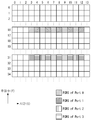
- the PCRS described above may be mapped using a frequency division multiplexing (FDM) method in a specific RB unit.
- FDM frequency division multiplexing
- the PCRS may be mapped to a specific RB unit (eg, 1 RB, 2 RB, etc.) using the FDM scheme.
- the PCRS transmitted through each antenna port may be mapped to a constant frequency tone interval or two consecutive frequency tones.
- Equation 16 shows an example of a mapping rule for mapping the PCRS at intervals of a constant frequency tone.
- k is the index of the frequency tone (or frequency domain)
- n_s is the starting physical resource block index or PCRS of the starting physical resource block of the PDSCH. Is the index of the first resource block where l is defined, l is the time domain index, and N set represents the total number of resource blocks.
- Equation 16 Silver Where n s is N set is Can be used.
- Equation 17 shows an example in which the changed parameter is used.
- p 0 , p 1 and p x represent the index of the antenna port through which the PNRS is transmitted.
- B denotes the number of unit RBs to which the PNRS transmitted per antenna port is mapped, that is, how many RBs are mapped to, where Q is the index of the last OFDM symbol to which the PNRS is mapped, and j is the PNRS mapping.
- each parameter value may be set based on MCS, numerology, carrier frequency and / or scheduled bandwidth.
- the terminal is a parameter related to the mapping pattern of the PCRS transmitted from the base station B, Q, j and Can be obtained through RRC / DCI signaling to recognize the mapping pattern of the PCRS.
- Equation 18 shows an example of a mapping rule for mapping the PCRS of each antenna port to a predetermined frequency tone interval when two antenna ports are provided.
- Equation 19 shows an example in which the parameter changed in Equation 18 is used.
- Equation 20 shows an example of a mapping rule for mapping PCRSs at intervals of consecutive frequency tones.
- Equation 22 shows an example of a mapping rule for mapping the PCRS of each antenna port to a continuous frequency tone when there are two antenna ports.
- Equation 23 shows an example in which the parameter changed in Equation 22 is used.
- the PCRS When PCRS is transmitted through two antenna ports, when the PCRS is mapped to a resource block using Equation 22, the PCRS may be mapped at consecutive frequency tone intervals as shown in FIG.
- Equation 24 shows an example of a mapping rule for arranging PCRSs of a specific antenna port on two frequency tones and arranging PCRSs of different antenna ports on consecutive frequency tones.
- the PCRS transmitted on the same antenna port is mapped to two frequency tones of one resource block. Therefore, since the PCRS is mapped to two frequency tones in one resource block, the density on the frequency axis of the PCRS is increased by 2 times than the mapping of the PCRS using Equations 16 to 23.
- the present embodiment can improve the estimation performance for the phase difference using the PCRS in the low SNR region.
- the PCRS can be used for additional channel estimation.
- This channel estimation can compensate for the deteriorated channel estimation result when the channel changes rapidly on the time axis.
- Equation 25 shows an example in which the parameter changed in Equation 24 is used.
- Equation 26 shows an example of a mapping rule for arranging PCRSs of a specific antenna port on two frequency tones when two antenna ports are arranged, and arranging PCRSs of different antenna ports on consecutive frequency tones.
- Equation 27 shows an example in which the parameter changed in Equation 26 is used.
- the PCRS of a specific antenna port is disposed on two frequency tones.
- the PCRSs of different antenna ports are arranged in consecutive frequency tones.
- the PCRS of antenna port 0 is mapped to frequency tone indexes x and 2x
- the PCRS of antenna port 1 is mapped to frequency tone indexes x + 1 and 2x + 1.
- the position of the frequency tone of the PNRS is determined by the equation.
- the position of the frequency tone of the PCRS is not determined by a specific equation, and may be the same as the position of the frequency tone of the antenna port through which the DMRS associated with the antenna port through which the PCRS is transmitted is transmitted.
- Equation 28 shows an example of PCRS mapping rules when the frequency tones of the antenna ports through which the DMRSs are transmitted are '16' and '31'.
- Equation 29 below shows an example in which the parameter changed in Equation 28 is used.
- PCRS for estimating phase noise may be mapped using frequency division multiplexing.
- 23 to 25 illustrate an example of a method of mapping a reference signal using a time division multiplexing method to which the present invention is applied.
- the PCRS transmitted through each antenna port may be mapped to a constant symbol interval or consecutive symbols in the time domain.
- Equation 30 Silver Where n s is N set is Can be used.
- Equation 31 shows an example in which the changed parameter is used.
- B denotes the number of unit RBs to which the PNRS transmitted per antenna port is mapped, that is, how many RBs are mapped to, where Q is the index of the last OFDM symbol to which the PNRS is mapped, and j is the PNRS mapping.
- the terminal is a parameter related to the mapping pattern of the PCRS transmitted from the base station B, Q, j and Can recognize the mapping pattern of the PCRS through RRC / DCI signaling.
- Equation 32 shows an example of a mapping rule for mapping the PCRS of each antenna port to a constant symbol interval when there are two antenna ports.
- Equation 33 shows an example in which the parameter changed in Equation 32 is used.
- m '(or second parameter) represents an RB index in a transmission band allocated to a specific terminal
- m' '(or, first parameter) represents PCRS between resource blocks to which PCRS is mapped. Parameter to change the mapping pattern of.
- the PCRS may be mapped as shown in FIG. 23. .
- the PCRSs of the antenna port 0 and the antenna port 1 are alternately alternately mapped to specific frequency tones at intervals of 1 symbol.
- Equation 34 shows an example of a mapping rule for arranging PCRSs of specific antenna ports on two frequency tones, and arranging PCRSs of different antenna ports on a time axis at specific symbol intervals using a TDM scheme.
- the PCRS When the PCRS is mapped to a resource block through Equation 34, the PCRS is mapped to two frequency tones of one resource block. Therefore, since the PCRS is mapped to two frequency tones in one resource block, the density on the frequency axis of the PCRS is increased by two times than the mapping of the PCRS using Equations 30 to 33.
- This channel estimation can compensate for the deteriorated channel estimation result when the channel changes rapidly on the time axis.
- Equation 36 when two antenna ports are used, a PCRS of a specific antenna port is arranged on two frequency tones, and a mapping rule for arranging PCRSs of different antenna ports on a time axis at a specific symbol interval using a TDM scheme An example is shown.
- Equation 37 shows an example in which a parameter changed in Equation 36 is used.
- the PCRS of a specific antenna port is disposed on two frequency tones.
- the PCRSs of different antenna ports are repeatedly arranged at regular intervals through a TDM scheme on a specific frequency tone.
- the position of the frequency tone of the PCRS is determined by the equation.
- the position of the frequency tone of the PCRS is not determined by a specific equation, and may be the same as the position of the frequency tone of the antenna port through which the DMRS associated with the antenna port through which the PCRS is transmitted is transmitted.
- Equation 38 shows an example of a mapping rule of the PCRS when the frequency tone of the antenna port through which the DMRS is transmitted is '24'.
- the PCRS is mapped to a specific frequency tone as shown in FIG.
- the specific frequency tone may be the same as the frequency tone to which the DMRS is mapped.
- PCRS for estimating phase noise may be mapped using time division multiplexing.
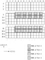
- the PCRS described above may be mapped using time division multiplexing and frequency division multiplexing in a specific RB unit.
- the PCRS may be mapped using a TDM scheme in a specific RB unit (for example, every 1 RB or every 2 RBs).
- the PCRS transmitted through each antenna port may be mapped to different frequency tones and different symbols using frequency division multiplexing and time division multiplexing according to the transmitted antenna port.
- Equation 40 shows an example of a mapping rule for mapping the PCRS with a constant frequency tone interval on the frequency axis domain and a constant symbol interval on the time axis domain according to the antenna pod transmitted.
- k is the index of the frequency tone (or frequency domain)
- Is the size of the resource block in the frequency domain or the number of frequency tones defined in one resource block (eg, 12)
- n s is the starting physical resource block index of the starting physical resource block of the PDSCH or The index of the first resource block in which the PCRS is defined
- l represents a time domain index
- N set represents the total number of resource blocks.
- Equation 40 Silver Where n s is N set is Can be used.
- p 0 , p 1 , p 2 , and p 3 represent the index of the antenna port through which the PCRS is transmitted.
- B denotes the number of unit RBs to which the PNRS transmitted per antenna port is mapped, that is, how many RBs are mapped to, where Q is the index of the last OFDM symbol to which the PNRS is mapped, and j is the PNRS mapping.
- signaling may be performed by RRC / DCI or a value preset in the transmitting / receiving end may be used.
- each parameter value may be set based on MCS, numerology, carrier frequency and / or scheduled bandwidth.
- the PCRS is mapped to the resource block at a constant frequency tone interval on the frequency axis domain and one symbol interval on the time axis domain. As shown, the PCRS may be mapped.
- the PCRSs of antenna port 0 and antenna port 1 are repeatedly mapped at regular symbol intervals at frequency tone index 'x', and the PCRS of antenna port 2 and antenna port 3 are frequency tone index '2x'. 'Is mapped repeatedly at regular symbol intervals.
- the PCRS When the PCRS is mapped to the resource block through Equation 42, the PCRS is mapped to two frequency tones of one resource block. Therefore, since the PCRS is mapped to two frequency tones in one resource block, the density on the frequency axis of the PCRS is doubled than the PCRS is mapped using Equations 40 and 41.
- This channel estimation can compensate for the deteriorated channel estimation result when the channel changes rapidly on the time axis.
- the PCRS When PCRS is transmitted through four antenna ports, when the PCRS is mapped to the resource block using Equations 42 and 43, the PCRS may be mapped as shown in FIG. 27.
- the PCRS of antenna port 0 and antenna port 1 is mapped to frequency tone indexes 'x' and '2x' using frequency division multiplexing
- the PCRS of antenna port 2 and antenna port 3 is frequency tone index 'x + 1'. Mapped to 'and' x + 2 '.
- the PCRSs of antenna port 0 and antenna port 1 are repeatedly mapped at regular symbol intervals at frequency tone indexes 'x' and '2x', and the PCRS of antenna port 2 and antenna port 3 is frequency At tone indices 'x + 1' and '2x + 1', they are repeatedly mapped at regular symbol intervals.
- the position of the frequency tone of the PCRS is determined by the equation.
- the position of the frequency tone of the PCRS is not determined by a specific equation, and may be the same as the position of the frequency tone of the antenna port through which the DMRS associated with the antenna port through which the PCRS is transmitted is transmitted.
- Equation 44 shows an example of PCRS mapping rules using TDM and FDM when DMRSs are transmitted at indexes '16' and '31' of frequency tones.
- PCRS for estimating phase noise may be mapped using a time division multiplexing method and a frequency division multiplexing method.
- 29 to 31 illustrate an example of a method of mapping a reference signal using time division multiplexing and code division multiplexing methods to which the present invention is applied.
- the PCRS described above may be mapped using a time division multiplexing and code division multiplexing method (CDM) in a specific RB unit.
- CDM code division multiplexing method
- the PCRS may be mapped using a TDM scheme and a CDM scheme in specific RB units (for example, every 1 RB or every 2 RBs).
- the PCRS transmitted on some antenna ports is arranged by separating the PCRS in the time domain using a TDM scheme, and the PCRS transmitted on the remaining antenna pods is It may be placed on the same frequency tone as the PCRS transmitted on the some antenna pods using a different sequence than the PCRS transmitted on the some antenna pods.
- k is the index of the frequency tone (or frequency domain)
- Is the size of the resource block in the frequency domain or the number of frequency tones defined in one resource block (eg, 12)
- n s is the starting physical resource block index of the starting physical resource block of the PDSCH or The index of the first resource block in which the PCRS is defined
- l represents a time domain index
- N set represents the total number of resource blocks.
- Equation 46 Silver Where n s is N set is Can be used.
- p 0 , p 1 , p 2 and p 3 represent the indexes of the antenna ports through which the PCRS is transmitted.
- B denotes the number of unit RBs to which the PNRS transmitted per antenna port is mapped, that is, how many RBs are mapped to, where Q is the index of the last OFDM symbol to which the PNRS is mapped, and j is the PNRS mapping.
- each parameter value may be set based on MCS, numerology, carrier frequency and / or scheduled bandwidth.
- the terminal is a parameter related to the mapping pattern of the PCRS transmitted from the base station B, Q, j and Can recognize the mapping pattern of the PCRS through RRC / DCI signaling.
- PCRSs transmitted at antenna ports 0 and 1 and antenna ports 2 and 3 are arranged at predetermined symbol intervals on different resource elements on the time axis using the TDM scheme at frequency tone indexes 'x' and 'x + 1'.
- the PCRSs transmitted at antenna ports 0 and 1 and antenna ports 2 and 3 are placed at frequency tone indexes 'x' and 'x + 1' using different sequences.
- the PCRS transmitted on the same antenna port may be arranged in a plurality of frequency tones to increase the density on the frequency axis of the PCRS.
- the PCRS of a particular antenna port is placed in multiple frequency tones.
- PCRSs on different antenna ports are placed on different symbols at regular symbol intervals via the TDM scheme on the time axis, and on the same frequency tone using different sequences via the CDM scheme.
- the present embodiment can improve the estimation performance for the phase difference using the PCRS in the low SNR region, and the PCRS can be used for additional channel estimation.
- Equation 49 shows an example in which the parameter changed in Equation 48 is used.
- the PCRS When PCRS is transmitted through four antenna ports, when the PCRS is mapped to a resource block using Equations 48 and 49, the PCRS may be mapped as shown in FIG. 30.
- the PCRS transmitted at antenna ports 0 and 1 and antenna ports 2 and 3 are TDM at four frequency tones, i.e., frequency tone indexes 'x', 'x + 1', '2x' and '2x + 1'.
- the PCRSs which are arranged at a certain symbol interval on different resource elements on the time axis by using the scheme, and are transmitted from antenna ports 0 and 1 and antenna ports 2 and 3, use frequency sequences of 'x' and 'x' using different sequences. +1 ',' 2x 'and' 2x + 1 '.
- the position of the frequency tone of the PCRS is determined by the equation.
- the position of the frequency tone of the PCRS is not determined by a specific equation, and may be the same as the position of the frequency tone of the antenna port through which the DMRS associated with the antenna port through which the PCRS is transmitted is transmitted.
- Equation 50 shows an example of a mapping rule of PCRS using TDM and CDM when DMRS is transmitted at indexes '23' and '24' of a frequency tone.
- the PCRS is mapped to the resource element according to Equation 50
- the PCRS is mapped to a specific frequency tone as shown in FIG.
- the specific frequency tone may be the same as the frequency tone to which the DMRS is mapped.
- Equation 51 shows an example in which the parameter changed in Equation 50 is used.
- PCRS for estimating phase noise is transmitted on multiple antenna ports on the same frequency tone by using time division multiplexing and code division multiplexing.
- PCRS can be deployed.
- the PCRS sequence r_ (n_s) (m) for generating the PCRS is defined as in Equation 52 below.
- the pseudo random sequence c (i) is defined by a gold sequence of length-31.
- Cinit the initialization value of m-sequence
- the parameter G value for determining the total length of the entire PCRS sequence is determined by the structure of the subframe (eg, DL only, self-contained, etc.) and the number of frequency tones to which the CDM scheme is applied in the unit RB. It may vary.
- the parameter G value is the parameter B, Q, j, Can be obtained from Eqs.
- Equations 55 and 56 below show an example for calculating a parameter G value when PCRS is transmitted through four antenna ports.
- PCRS sequence Is a complex-valued modulation symbol of a subframe according to Equation 57 or 58 below. Is mapped to.
- Equations 57 and 58 represent resource elements for frequency domain index k and time domain index l, Denotes the value of the resource element (k, l) for antenna port p in Table 6 below.
- the base station When the base station transmits the PCRS on a plurality of antenna ports, the base station may signal information (antenna port information) on the antenna port through which the actual PCRS is transmitted to the terminal in an explicit or implicit manner through RRC and / or DCI.
- the antenna port through which the PCRS associated with the antenna port through which the DRMS is transmitted is transmitted based on a preset (or promised) configuration at the transmitting / receiving end using the received information. Can be recognized.
- the terminal may receive the PCRS through the recognized antenna port.
- the base station When the base station explicitly informs the terminal of the information of the antenna port through which the PCRS is transmitted, the base station may directly signal information about the antenna port through which the PNRS is transmitted by the specific terminal through RRC and / or DCI.
- the signaled information may include an index of the antenna port through which the PCRS is transmitted, the total number of antenna ports through which the PCRS set in the system is transmitted, and the number of antenna ports used by the base station to transmit the PCRS.
- the base station may transmit information on each antenna port through which the PCRS is transmitted to the terminal, and the terminal may receive the PCRS to be used through the received information.
- phase noise may be estimated by estimating a Common Phase Error (CPE) / Carrier Frequency Offset (CFO) value through the received PCRS.
- CPE Common Phase Error
- CFO Carrier Frequency Offset
- the base station generates a PTRS (or PCRS, or PNRS, or a first reference signal) (S32010).
- a PTRS or PCRS, or PNRS, or a first reference signal
- the PTRS is generated through the PTRS sequence as described above.
- PTRS is a signal used to accurately receive the distorted signal by estimating the phase noise due to the CPE and the CFO when the signal transmitted from the base station is distorted as described above, and is shared in advance between the terminal and the base station. May be a signal.
- PTRS may be generated through the PTRS sequence as described above.
- PTRSs transmitted on different antenna ports using TDM and / or FDM schemes are placed (or mapped) on specific symbols on different time axis domains and specific frequency tones on frequency axis domains, or CDM schemes.
- PTRSs transmitted on different antenna ports can be generated using different PTRS sequences.
- At least one parameter may be the parameters B, Q, j, described in Equations 16 to 51 of FIGS. 19 to 31. It may include and may be transmitted through the above-described DCI and / or RRC signaling.
- FIG 33 is a diagram illustrating an example of an internal block diagram of a wireless device to which the present invention can be applied.
- the wireless device may be a base station and a terminal, and the base station includes both a macro base station and a small base station.
- the base station 3310 and the UE 3320 include a communication unit (transmitter and receiver, RF unit, 3313 and 3323), a processor 3311 and 3321, and a memory 3312 and 3322.
- the base station and the UE may further include an input unit and an output unit.
- the communication units 3313 and 3323, the processors 3311 and 3321, the input unit, the output unit, and the memory 3312 and 3322 are functionally connected to perform the method proposed in the present specification.
- the communication unit may also include a switch function for switching the transmission and reception functions.
- Processors 3311 and 3331 implement the functions, processes and / or methods proposed herein. Layers of the air interface protocol may be implemented by a processor.
- the processor may be represented by a controller, a controller, a control unit, a computer, or the like.
- the memories 3312 and 3322 are connected to a processor and store protocols or parameters for performing an uplink resource allocation method.
- Processors 3311 and 3321 may include application-specific integrated circuits (ASICs), other chipsets, logic circuits, and / or data processing devices.
- the memory may include read-only memory (ROM), random access memory (RAM), flash memory, memory card, storage medium and / or other storage device.
- the communication unit may include a baseband circuit for processing a wireless signal.
- the above-described technique may be implemented as a module (process, function, etc.) for performing the above-described function.
- the module may be stored in memory and executed by a processor.
- the memory may be internal or external to the processor and may be coupled to the processor by various well known means.
- the output unit (display unit or display unit) is controlled by a processor and outputs information output from the processor together with a key input signal generated at the key input unit and various information signals from the processor.
- Orientation-based device discovery method is not limited to the configuration and method of the embodiments described as described above, the embodiments are all or part of each of the embodiments is optional so that various modifications can be made It may be configured in combination.
- the direction-based device search method of the present specification may be implemented as processor-readable code in a processor-readable recording medium provided in a network device.
- the processor-readable recording medium includes all kinds of recording devices that store data that can be read by the processor. Examples of the processor-readable recording medium include ROM, RAM, CD-ROM, magnetic tape, floppy disk, optical data storage device, and the like, and may also be implemented in the form of a carrier wave such as transmission over the Internet. .
- the processor-readable recording medium can also be distributed over network coupled computer systems so that the processor-readable code is stored and executed in a distributed fashion.
- the RRC connection method has been described with reference to an example applied to the 3GPP LTE / LTE-A system.
- the RRC connection method may be applied to various wireless communication systems in addition to the 3GPP LTE / LTE-A system.
Landscapes
- Engineering & Computer Science (AREA)
- Computer Networks & Wireless Communication (AREA)
- Signal Processing (AREA)
- Power Engineering (AREA)
- Mobile Radio Communication Systems (AREA)
Abstract
L'invention concerne un procédé et un appareil d'exécution d'un suivi de phase dans un système de communications sans fil. La présente invention peut fournir un procédé et un appareil d'exécution d'un suivi de phase. Le procédé comprend les étapes consistant à : recevoir au moins un paramètre, d'une station de base, le ou les paramètres indiquant des emplacements de tonalités de fréquence et des symboles dans une zone de ressource spécifique sur laquelle au moins un premier signal de référence est mappé ; recevoir le ou les premiers signaux de référence utilisés pour le suivi de phase, de la station de base, via la zone de ressource spécifique, le ou les premiers signaux de référence étant mappés sur un symbole spécifique dans un domaine temporel et une tonalité de fréquence spécifique dans un domaine fréquentiel, le symbole spécifique et la tonalité de fréquence spécifique étant différents pour chaque port d'antenne via lequel le premier signal de référence est transmis ; et exécuter le suivi de phase sur la base du ou des premiers signaux de référence.
Applications Claiming Priority (2)
| Application Number | Priority Date | Filing Date | Title |
|---|---|---|---|
| US201662338464P | 2016-05-18 | 2016-05-18 | |
| US62/338,464 | 2016-05-18 |
Publications (1)
| Publication Number | Publication Date |
|---|---|
| WO2017200315A1 true WO2017200315A1 (fr) | 2017-11-23 |
Family
ID=60325290
Family Applications (1)
| Application Number | Title | Priority Date | Filing Date |
|---|---|---|---|
| PCT/KR2017/005170 Ceased WO2017200315A1 (fr) | 2016-05-18 | 2017-05-18 | Procédé de suivi de bruit de phase dans un système de communications sans fil, et appareil associé |
Country Status (1)
| Country | Link |
|---|---|
| WO (1) | WO2017200315A1 (fr) |
Cited By (22)
| Publication number | Priority date | Publication date | Assignee | Title |
|---|---|---|---|---|
| US20180205528A1 (en) * | 2017-01-13 | 2018-07-19 | Qualcomm Incorporated | Systems and methods to select or transmitting frequency domain patterns for phase tracking reference signals |
| WO2019103552A1 (fr) * | 2017-11-24 | 2019-05-31 | Samsung Electronics Co., Ltd. | Décalage d'élément de ressource dans un système de télécommunication |
| WO2019103550A1 (fr) * | 2017-11-24 | 2019-05-31 | 엘지전자 주식회사 | Procédé d'émission ou de réception de signal de liaison descendante entre un terminal et une station de base dans un système de communication sans fil, et appareil prenant en charge celui-ci |
| WO2019112374A1 (fr) * | 2017-12-07 | 2019-06-13 | Lg Electronics Inc. | Procédé de transmission de signal de référence de suivi de phase de liaison montante par un équipement d'utilisateur dans un système de communication sans fil et appareil prenant en charge ledit procédé |
| WO2019135650A1 (fr) * | 2018-01-07 | 2019-07-11 | 엘지전자 주식회사 | Procédé d'émission et de réception de signal de référence de suivi de phase entre un terminal et une station de base dans un système de communication sans fil, et dispositif prenant en charge le procédé |
| WO2019160385A1 (fr) * | 2018-02-16 | 2019-08-22 | Samsung Electronics Co., Ltd. | Augmentation de la puissance du signal de référence dans un système de télécommunication par référence croisée à des applications connexes |
| WO2019161539A1 (fr) * | 2018-02-23 | 2019-08-29 | Lenovo (Beijing) Limited | Détermination d'un précodeur destiné à des ports ptrs |
| CN111130728A (zh) * | 2018-10-31 | 2020-05-08 | 维沃移动通信有限公司 | 一种传输方法、终端及网络侧设备 |
| CN111314009A (zh) * | 2020-02-19 | 2020-06-19 | 中国科学院自动化研究所 | 目标射电源跟踪观测的数字接收装置、系统及方法 |
| CN111490861A (zh) * | 2019-01-26 | 2020-08-04 | 上海朗帛通信技术有限公司 | 一种被用于无线通信的用户设备、基站中的方法和装置 |
| WO2020222606A1 (fr) * | 2019-05-02 | 2020-11-05 | 엘지전자 주식회사 | Procédé d'émission et de réception de signal de référence de suivi de phase dans un système de communication sans fil, et appareil associé |
| CN112383495A (zh) * | 2020-11-03 | 2021-02-19 | 上海擎昆信息科技有限公司 | 一种基于pt-rs的频偏估计方法及系统 |
| WO2021066624A1 (fr) * | 2019-10-03 | 2021-04-08 | 엘지전자 주식회사 | Procédé d'émission et de réception de pdsch dans un système de communication sans fil, et dispositif à cet effet |
| US11070335B2 (en) | 2017-01-13 | 2021-07-20 | Qualcomm Incorporated | Apparatus and method for determining resources for phase tracking reference signal (PT-RS) pilot signals using frequency domain patterns |
| CN113475013A (zh) * | 2019-02-14 | 2021-10-01 | 苹果公司 | Nr的接收天线相对相位测量 |
| WO2022068936A1 (fr) * | 2020-09-30 | 2022-04-07 | 华为技术有限公司 | Procédé et appareil de mappage de signaux de référence |
| US20220166565A1 (en) * | 2017-04-28 | 2022-05-26 | Panasonic Intellectual Property Corporation Of America | Measurement apparatus and measurement method |
| CN114946162A (zh) * | 2019-11-07 | 2022-08-26 | 弗劳恩霍夫应用研究促进协会 | 用于交错的参考信号的模糊/混叠消除或减少 |
| CN115606134A (zh) * | 2020-05-14 | 2023-01-13 | 苹果公司(Us) | 用于极高频谱中的相位噪声降低的系统和方法 |
| TWI814807B (zh) * | 2018-04-10 | 2023-09-11 | 美商高通公司 | 在新無線電(nr)中對直流(dc)音調位置的上行鏈路用信號傳輸 |
| US11824805B2 (en) | 2017-06-12 | 2023-11-21 | Panasonic Intellectual Property Corporation Of America | Transmitter, receiver, transmission method, and reception method with phase tracking reference signal mapping |
| WO2024197493A1 (fr) * | 2023-03-25 | 2024-10-03 | 华为技术有限公司 | Procédé et appareil de communication |
Citations (4)
| Publication number | Priority date | Publication date | Assignee | Title |
|---|---|---|---|---|
| US20070036247A1 (en) * | 2005-08-12 | 2007-02-15 | Stmicroelectronics Belgium Nv | Receiver with frequency offset compensation for M-state phase modulation |
| US20120120905A1 (en) * | 2009-08-14 | 2012-05-17 | Lg Electronics Inc. | Method and device for transmitting a downlink reference signal in a wireless communication system supporting multiple antennas |
| US20130322582A1 (en) * | 2011-02-24 | 2013-12-05 | Nec Casio Mobile Communications, Ltd. | Receiver, receiving method, and computer program |
| US20160006594A1 (en) * | 2013-03-28 | 2016-01-07 | Telefonaktiebolaget L M Ericsson (Publ) | A phase reference symbol format for ofdm phase synchronization |
-
2017
- 2017-05-18 WO PCT/KR2017/005170 patent/WO2017200315A1/fr not_active Ceased
Patent Citations (4)
| Publication number | Priority date | Publication date | Assignee | Title |
|---|---|---|---|---|
| US20070036247A1 (en) * | 2005-08-12 | 2007-02-15 | Stmicroelectronics Belgium Nv | Receiver with frequency offset compensation for M-state phase modulation |
| US20120120905A1 (en) * | 2009-08-14 | 2012-05-17 | Lg Electronics Inc. | Method and device for transmitting a downlink reference signal in a wireless communication system supporting multiple antennas |
| US20130322582A1 (en) * | 2011-02-24 | 2013-12-05 | Nec Casio Mobile Communications, Ltd. | Receiver, receiving method, and computer program |
| US20160006594A1 (en) * | 2013-03-28 | 2016-01-07 | Telefonaktiebolaget L M Ericsson (Publ) | A phase reference symbol format for ofdm phase synchronization |
Non-Patent Citations (1)
| Title |
|---|
| NOKIA: "On the Phase Noise Model for 5G New Radio Evaluation", R1 -162885, 3GPP TSG-RAN WG1 MEETING #84BIS, 15 April 2016 (2016-04-15), Busan, Korea, XP051079726 * |
Cited By (51)
| Publication number | Priority date | Publication date | Assignee | Title |
|---|---|---|---|---|
| US10560243B2 (en) * | 2017-01-13 | 2020-02-11 | Qualcomm Incorporated | Systems and methods to select or transmitting frequency domain patterns for phase tracking reference signals |
| US11522656B2 (en) | 2017-01-13 | 2022-12-06 | Qualcomm Incorporated | Apparatus and method for determining resources for phase tracking reference signal (PT-RS) pilot signals using frequency domain patterns |
| US11070335B2 (en) | 2017-01-13 | 2021-07-20 | Qualcomm Incorporated | Apparatus and method for determining resources for phase tracking reference signal (PT-RS) pilot signals using frequency domain patterns |
| US20180205528A1 (en) * | 2017-01-13 | 2018-07-19 | Qualcomm Incorporated | Systems and methods to select or transmitting frequency domain patterns for phase tracking reference signals |
| US11711178B2 (en) * | 2017-04-28 | 2023-07-25 | Panasonic Intellectual Property Corporation Of America | Measurement apparatus and measurement method |
| US20220166565A1 (en) * | 2017-04-28 | 2022-05-26 | Panasonic Intellectual Property Corporation Of America | Measurement apparatus and measurement method |
| US11824805B2 (en) | 2017-06-12 | 2023-11-21 | Panasonic Intellectual Property Corporation Of America | Transmitter, receiver, transmission method, and reception method with phase tracking reference signal mapping |
| US12177149B2 (en) | 2017-06-12 | 2024-12-24 | Panasonic Intellectual Property Corporation Of America | Transmitter, receiver, transmission method, and reception method |
| US11206657B2 (en) | 2017-11-24 | 2021-12-21 | Samsung Electronics Co., Ltd. | Resource element offsetting in a telecommunication system |
| WO2019103552A1 (fr) * | 2017-11-24 | 2019-05-31 | Samsung Electronics Co., Ltd. | Décalage d'élément de ressource dans un système de télécommunication |
| WO2019103550A1 (fr) * | 2017-11-24 | 2019-05-31 | 엘지전자 주식회사 | Procédé d'émission ou de réception de signal de liaison descendante entre un terminal et une station de base dans un système de communication sans fil, et appareil prenant en charge celui-ci |
| US10355842B2 (en) | 2017-12-07 | 2019-07-16 | Lg Electronics Inc. | Method of transmitting uplink phase tracking reference signal by user equipment in wireless communication system and apparatus supporting same |
| WO2019112374A1 (fr) * | 2017-12-07 | 2019-06-13 | Lg Electronics Inc. | Procédé de transmission de signal de référence de suivi de phase de liaison montante par un équipement d'utilisateur dans un système de communication sans fil et appareil prenant en charge ledit procédé |
| US10644855B2 (en) | 2017-12-07 | 2020-05-05 | Lg Electronics Inc. | Method of transmitting uplink phase tracking reference signal by user equipment in wireless communication system and apparatus supporting same |
| US10554360B2 (en) | 2017-12-07 | 2020-02-04 | Lg Electronics Inc. | Method of transmitting uplink phase tracking reference signal by user equipment in wireless communication system and apparatus supporting same |
| RU2742044C1 (ru) * | 2017-12-07 | 2021-02-02 | ЭлДжи ЭЛЕКТРОНИКС ИНК. | Способ передачи опорного сигнала отслеживания фазы восходящей линии связи пользовательским оборудованием в системе беспроводной связи и устройство, поддерживающее его |
| US10594458B2 (en) | 2017-12-07 | 2020-03-17 | Lg Electronics Inc. | Method of transmitting uplink phase tracking reference signal by user equipment in wireless communication system and apparatus supporting same |
| US10999031B2 (en) | 2017-12-07 | 2021-05-04 | Lg Electronics Inc. | Method of transmitting uplink phase tracking reference signal by user equipment in wireless communication system and apparatus supporting same |
| WO2019135650A1 (fr) * | 2018-01-07 | 2019-07-11 | 엘지전자 주식회사 | Procédé d'émission et de réception de signal de référence de suivi de phase entre un terminal et une station de base dans un système de communication sans fil, et dispositif prenant en charge le procédé |
| US11283506B2 (en) | 2018-01-07 | 2022-03-22 | Lg Electronics Inc. | Method for transmitting and receiving phase tracking reference signal between terminal and base station in wireless communication system, and device for supporting same |
| US11811478B2 (en) | 2018-01-07 | 2023-11-07 | Lg Electronics Inc. | Method for transmitting and receiving phase tracking reference signal between terminal and base station in wireless communication system, and device for supporting same |
| WO2019160385A1 (fr) * | 2018-02-16 | 2019-08-22 | Samsung Electronics Co., Ltd. | Augmentation de la puissance du signal de référence dans un système de télécommunication par référence croisée à des applications connexes |
| US11115932B2 (en) | 2018-02-16 | 2021-09-07 | Samsung Electronics Co., Ltd. | Reference signal power boosting in a telecommunication system |
| WO2019161539A1 (fr) * | 2018-02-23 | 2019-08-29 | Lenovo (Beijing) Limited | Détermination d'un précodeur destiné à des ports ptrs |
| CN111742515A (zh) * | 2018-02-23 | 2020-10-02 | 联想(北京)有限公司 | 确定用于ptrs端口的预编码器 |
| CN111742515B (zh) * | 2018-02-23 | 2022-10-14 | 联想(北京)有限公司 | 确定用于ptrs端口的预编码器 |
| US11411619B2 (en) | 2018-02-23 | 2022-08-09 | Lenovo (Beijing) Limited | Determining a precoder for PTRS ports |
| TWI814807B (zh) * | 2018-04-10 | 2023-09-11 | 美商高通公司 | 在新無線電(nr)中對直流(dc)音調位置的上行鏈路用信號傳輸 |
| US11825476B2 (en) | 2018-04-10 | 2023-11-21 | Qualcomm Incorporated | Communication of direct current (DC) tone location |
| CN111130728A (zh) * | 2018-10-31 | 2020-05-08 | 维沃移动通信有限公司 | 一种传输方法、终端及网络侧设备 |
| CN111130728B (zh) * | 2018-10-31 | 2023-08-25 | 维沃移动通信有限公司 | 一种传输方法、终端及网络侧设备 |
| CN114844613A (zh) * | 2019-01-26 | 2022-08-02 | 上海朗帛通信技术有限公司 | 一种被用于无线通信的用户设备、基站中的方法和装置 |
| CN111490861B (zh) * | 2019-01-26 | 2022-05-24 | 上海朗帛通信技术有限公司 | 一种被用于无线通信的用户设备、基站中的方法和装置 |
| CN114844613B (zh) * | 2019-01-26 | 2024-03-01 | 上海朗帛通信技术有限公司 | 一种被用于无线通信的用户设备、基站中的方法和装置 |
| CN111490861A (zh) * | 2019-01-26 | 2020-08-04 | 上海朗帛通信技术有限公司 | 一种被用于无线通信的用户设备、基站中的方法和装置 |
| US12057892B2 (en) | 2019-02-14 | 2024-08-06 | Apple Inc. | Receive antenna relative phase measurements for NR |
| CN113475013B (zh) * | 2019-02-14 | 2024-03-22 | 苹果公司 | Nr的接收天线相对相位测量方法、用户设备及介质 |
| CN113475013A (zh) * | 2019-02-14 | 2021-10-01 | 苹果公司 | Nr的接收天线相对相位测量 |
| WO2020222606A1 (fr) * | 2019-05-02 | 2020-11-05 | 엘지전자 주식회사 | Procédé d'émission et de réception de signal de référence de suivi de phase dans un système de communication sans fil, et appareil associé |
| US11916830B2 (en) | 2019-05-02 | 2024-02-27 | Lg Electronics Inc. | Method for transmitting and receiving phase tracking reference signal in wireless communication system, and apparatus therefor |
| US12289263B2 (en) | 2019-05-02 | 2025-04-29 | Lg Electronics Inc. | Method for transmitting and receiving phase tracking reference signal in wireless communication system, and apparatus therefor |
| WO2021066624A1 (fr) * | 2019-10-03 | 2021-04-08 | 엘지전자 주식회사 | Procédé d'émission et de réception de pdsch dans un système de communication sans fil, et dispositif à cet effet |
| US12137453B2 (en) | 2019-10-03 | 2024-11-05 | Lg Electronics Inc. | Method for transmitting and receiving PDSCH in wireless communication system, and device for same |
| CN114946162A (zh) * | 2019-11-07 | 2022-08-26 | 弗劳恩霍夫应用研究促进协会 | 用于交错的参考信号的模糊/混叠消除或减少 |
| US12267197B2 (en) | 2019-11-07 | 2025-04-01 | Fraunhofer-Gesellschaft zur Förderung der angewandten Forschung e.V. | Ambiguity/aliasing cancellation or reduction for staggered reference signals |
| CN111314009A (zh) * | 2020-02-19 | 2020-06-19 | 中国科学院自动化研究所 | 目标射电源跟踪观测的数字接收装置、系统及方法 |
| CN115606134A (zh) * | 2020-05-14 | 2023-01-13 | 苹果公司(Us) | 用于极高频谱中的相位噪声降低的系统和方法 |
| WO2022068936A1 (fr) * | 2020-09-30 | 2022-04-07 | 华为技术有限公司 | Procédé et appareil de mappage de signaux de référence |
| CN112383495A (zh) * | 2020-11-03 | 2021-02-19 | 上海擎昆信息科技有限公司 | 一种基于pt-rs的频偏估计方法及系统 |
| CN112383495B (zh) * | 2020-11-03 | 2021-06-22 | 上海擎昆信息科技有限公司 | 一种基于pt-rs的频偏估计方法及系统 |
| WO2024197493A1 (fr) * | 2023-03-25 | 2024-10-03 | 华为技术有限公司 | Procédé et appareil de communication |
Similar Documents
| Publication | Publication Date | Title |
|---|---|---|
| WO2017200315A1 (fr) | Procédé de suivi de bruit de phase dans un système de communications sans fil, et appareil associé | |
| WO2018225927A1 (fr) | Procédé d'émission/de réception d'un signal de référence dans un système de communication sans fil et dispositif associé | |
| WO2018203592A1 (fr) | Procédé de transmission/réception d'un signal de référence dans un système de communication sans fil, et dispositif associé | |
| WO2017213326A1 (fr) | Procédé d'émission et de réception de signaux de référence de compensation de bruit de phase dans un système de communication sans fil, et appareil associé | |
| WO2018143537A1 (fr) | Procédé de suivi de bruit de phase dans un système de communication sans fil, et dispositif associé | |
| WO2018182150A1 (fr) | Procédé d'émission et de réception de signaux de référence dans un système de communication sans fil et dispositif associé | |
| WO2018203726A1 (fr) | Appareil et procédé de communication d'un signal de référence destiné à un canal de diffusion | |
| WO2015133825A1 (fr) | Procédé de réception d'informations de commande pour recevoir un signal de référence de découverte et appareil associé | |
| WO2018225935A1 (fr) | Procédé de transmission/réception de signal de référence dans un système de communications sans fil, et dispositif associé | |
| WO2019139298A1 (fr) | Procédé de transmission et de réception de canal d'accès aléatoire sans fil, et dispositif associé | |
| WO2018182358A1 (fr) | Procédé destiné à l'émission et à la réception d'un signal de référence dans un système de communication sans fil et dispositif associé | |
| WO2018182256A1 (fr) | Procédé pour rapporter des informations d'état de canal dans un système de communication sans fil, et appareil associé | |
| WO2018026253A1 (fr) | Procédé de transmission de demande de programmation dans un système de communications sans fil, et appareil s'y rapportant | |
| WO2019098769A1 (fr) | Procédé d'émission et de réception de signal de référence et dispositif associé | |
| WO2018203616A1 (fr) | Procédé de réception de signal de synchronisation et dispositif associé | |
| WO2019088787A1 (fr) | Procédé d'émission et de réception d'une pluralité de longs pucch basés sur des créneaux dans un système de communication sans fil et appareil pour cela | |
| WO2018084661A1 (fr) | Procédé d'émission et de réception de canal physique de commande de liaison montante entre terminal et station de base dans un système de communication sans fil et appareil pour sa prise en charge | |
| WO2014107088A1 (fr) | Procédé et appareil d'émission/réception de signaux | |
| WO2019098772A1 (fr) | Procédé et appareil permettant de réaliser une communication de liaison latérale dans un système de communication sans fil | |
| WO2018143721A1 (fr) | Procédé de signalement d'informations d'état de canal dans un système de communications sans fil, et appareil associé | |
| WO2017135674A1 (fr) | Procédé de communication dans un réseau prenant en charge des bandes sous licence et sans licence | |
| WO2017146342A1 (fr) | Procédé de réception d'informations de système dans un système de communication sans fil d'internet des objets à bande étroite, et dispositif associé | |
| WO2015182970A1 (fr) | Procédé pour réaliser une mesure de signal de découverte et équipement utilisateur | |
| WO2019066619A1 (fr) | Procédé de notification d'informations d'état de canal apériodiques dans un système de communication sans fil et dispositif associé | |
| WO2015108308A1 (fr) | Procédé pour exécuter une procédure de recherche de cellule, et équipement d'utilisateur pour exécuter une procédure de recherche d'après un signal de recherche dans un système de communications sans fil |
Legal Events
| Date | Code | Title | Description |
|---|---|---|---|
| NENP | Non-entry into the national phase |
Ref country code: DE |
|
| 121 | Ep: the epo has been informed by wipo that ep was designated in this application |
Ref document number: 17799672 Country of ref document: EP Kind code of ref document: A1 |
|
| 122 | Ep: pct application non-entry in european phase |
Ref document number: 17799672 Country of ref document: EP Kind code of ref document: A1 |