WO2017203590A1 - Système de vol pour véhicule volant, et procédé de vol pour véhicule volant - Google Patents
Système de vol pour véhicule volant, et procédé de vol pour véhicule volant Download PDFInfo
- Publication number
- WO2017203590A1 WO2017203590A1 PCT/JP2016/065271 JP2016065271W WO2017203590A1 WO 2017203590 A1 WO2017203590 A1 WO 2017203590A1 JP 2016065271 W JP2016065271 W JP 2016065271W WO 2017203590 A1 WO2017203590 A1 WO 2017203590A1
- Authority
- WO
- WIPO (PCT)
- Prior art keywords
- power
- flying
- flight
- flying object
- power transmission
- Prior art date
- Legal status (The legal status is an assumption and is not a legal conclusion. Google has not performed a legal analysis and makes no representation as to the accuracy of the status listed.)
- Ceased
Links
Images



Classifications
-
- B—PERFORMING OPERATIONS; TRANSPORTING
- B64—AIRCRAFT; AVIATION; COSMONAUTICS
- B64U—UNMANNED AERIAL VEHICLES [UAV]; EQUIPMENT THEREFOR
- B64U50/00—Propulsion; Power supply
- B64U50/30—Supply or distribution of electrical power
- B64U50/37—Charging when not in flight
- B64U50/38—Charging when not in flight by wireless transmission
-
- H—ELECTRICITY
- H02—GENERATION; CONVERSION OR DISTRIBUTION OF ELECTRIC POWER
- H02J—ELECTRIC POWER NETWORKS; CIRCUIT ARRANGEMENTS OR SYSTEMS FOR SUPPLYING OR DISTRIBUTING ELECTRIC POWER; SYSTEMS FOR STORING ELECTRIC ENERGY
- H02J50/00—Circuit arrangements or systems for wireless supply or distribution of electric power
- H02J50/10—Circuit arrangements or systems for wireless supply or distribution of electric power using inductive coupling
- H02J50/12—Circuit arrangements or systems for wireless supply or distribution of electric power using inductive coupling of the resonant type
-
- B—PERFORMING OPERATIONS; TRANSPORTING
- B64—AIRCRAFT; AVIATION; COSMONAUTICS
- B64U—UNMANNED AERIAL VEHICLES [UAV]; EQUIPMENT THEREFOR
- B64U10/00—Type of UAV
- B64U10/10—Rotorcrafts
- B64U10/13—Flying platforms
-
- B—PERFORMING OPERATIONS; TRANSPORTING
- B64—AIRCRAFT; AVIATION; COSMONAUTICS
- B64U—UNMANNED AERIAL VEHICLES [UAV]; EQUIPMENT THEREFOR
- B64U70/00—Launching, take-off or landing arrangements
Definitions
- the present invention relates to a flying system of a flying object and a flying method of a flying object.
- Patent Document 1 describes a method for supporting landing of an unmanned air vehicle.
- the unmanned air vehicle determines whether or not landing is necessary during autonomous flight based on predetermined conditions, and if it determines that landing is necessary, it automatically sets the landing target point and receives radio signals. When it is determined that the electric field strength is greater than or equal to the threshold, autonomous flight is started toward the landing target point.
- Patent Document 2 describes an automatic battery charger for unmanned vehicles.
- the battery automatic charging device includes an optical receiving device fixed at a position where an optical signal from the optical transmitting device can be received when the unmanned vehicle stops at a predetermined position in order to charge the battery by the power feeding means.
- Patent Document 3 describes a technique for stably supplying power while maintaining a target transmission efficiency from a power transmission apparatus to a power reception apparatus in a system that performs magnetic resonance type non-contact power supply.
- the power receiving device is provided in the inner space of the power receiving coil, and the power receiving side adjusting coil is supported by the winding axis so that the direction of the winding axis is rotatable with respect to the direction of the winding axis of the power receiving coil.
- a power receiving side angle adjusting mechanism for changing a resonance frequency of the power receiving side resonance circuit.
- Patent Document 4 discloses a non-contact power transmission device that transmits power in a non-contact manner by electromagnetic induction to a power reception device including a power reception coil and a fixed capacitor electrically connected to the power reception coil in parallel.
- a variable capacitor is electrically connected in series to a power transmission coil electrically connected to an AC power supply, and the phase difference between the voltage phase and current phase of AC power is reduced.
- the capacitance value of a variable capacitor is controlled.
- Patent Document 5 in a power feeding system having a power transmitting device having a primary coil and a power receiving device having a secondary coil, the power receiving device adjusts the value of the current supplied to the load to be a predetermined value. It is described.
- the power receiving device has a secondary side coil that generates a second current in response to a first current supplied to the primary side coil, and a value of a third current that is generated from the second current and supplied to the load. And an adjusting device for adjusting the value to be a value.
- Patent Document 6 describes an exploration system for an object to be investigated that uses magnetic resonance type non-contact power feeding.
- the impedance of the power transmission circuit changes according to the distance between the power transmission circuit and the power reception circuit, and if the relationship between the distance and the impedance (or power consumption) is known in advance, It describes that the distance between the two can be grasped from the power consumption.
- JP 2011-240745 A JP-A-2-290105 Japanese Patent No. 5897777 JP 2013-70590 A Japanese Patent No. 5635215 Japanese Patent No. 5877422
- Electric flying vehicles must be equipped with heavy batteries on the aircraft during the flight, which can improve flight performance and ease of handling. It has become a drag.
- the power consumption per unit time is increased and the flight time is shortened (so-called power density (output weight ratio) is reduced), and the motion performance of the aircraft is also reduced.
- the impact at the time of crash or collision increases due to the weight increase, and it becomes difficult to ensure durability and safety.
- the battery needs to be charged before flight, and the number of flights is limited accordingly. Furthermore, since the battery is a consumable item, it must be replaced periodically, and the running cost is high.
- the present invention has been made to solve these problems, and an object of the present invention is to provide a flying system of a flying object and a flying method of the flying object that can improve the flight performance and handling of the flying object. It is said.
- one of the present inventions is a flying system of a flying object, a power receiving device that receives power by a magnetic resonance type non-contact power feeding, and flight by the power received by the power receiving device
- a flying body having a thrust generating mechanism for obtaining a thrust for, and a power transmission device that is provided apart from the flying body and supplies power to the power receiving device by the non-contact power feeding during the flight of the flying body; Is provided.
- the flight system of the present invention supplies electric power to the flying vehicle using non-contact power feeding, and the flying vehicle uses the received power to obtain thrust. It may not be installed or have a small capacity as required in an emergency, and the weight of the flying object can be reduced. In addition, the weight reduction can improve the flight performance of the flying object, and the impact at the time of crash or collision can be alleviated, and the durability and safety can be improved. In addition, since there is no restriction on the flight time, for example, it is possible to practice for a long time. Moreover, charging before the flight is not necessary, and the burden of charging is also released. In addition, since the battery is not mounted on the flying object, or has a small capacity (light weight) / low price, the running cost can be suppressed.
- Another aspect of the present invention is a flying system of the above-mentioned flying object, which is an area set in an area where power can be transmitted from the power transmitting device to the power receiving device by the non-contact power feeding.
- an information processing device that performs control to reduce the power transmitted from the power transmission device when it is determined that the power does not exist in the area.
- the information processing device when the information processing device determines that the flying object does not exist in the flying area, the information processing device reduces the power transmitted from the power transmitting device, so that the flying object moves to a place away from the flying area. Can be prevented. Therefore, the flying object can fly safely.
- Another aspect of the present invention is a flying system for a flying object including a power measurement circuit that measures power transmitted by the power transmission device, and the information processing device measures the power measurement circuit. Based on the change in electric power, it is determined whether or not the flying object exists in the flight area.
- the power transmitted by the power transmission device (current of the resonance circuit on the power transmission side) changes depending on the position where the flying object (power receiving device) exists.
- the position of the flying object can be estimated from the change in the power transmitted by the power transmission device.
- the power transmission device includes a power transmission coil that forms a resonance circuit, and is communicably connected to the flying object.
- the power received by the power receiving device is acquired, the transmission efficiency is obtained from the ratio of the power supplied by the power transmitting device and the power received by the power receiving device, and the inductance of the power transmission coil is set so that the transmission efficiency is increased.
- An information processing device for adjusting is further provided.
- the power transmission device includes a capacitive element that forms a resonance circuit, and is communicably connected to the flying object. Acquiring power received by the power receiving device, obtaining transmission efficiency from a ratio of power supplied by the power transmitting device and power received by the power receiving device, and reducing the capacitance of the capacitive element so as to increase the transmission efficiency.
- Another aspect of the present invention is a flying system for a flying object, a transmitter for wirelessly transmitting a control instruction for the flying object, and a receiver for receiving the control signal provided in the flying object. And a flight control device that is provided in the flying body and performs flight control of the flying body in accordance with a control signal received by the receiver.
- the present invention can be applied to a case where the flying object is remotely controlled by a radio signal.
- Another one of the present inventions is a flight system for the above-mentioned flying object, and includes a flight control device that autonomously controls its flight so that the flying object is located in the flight area.
- the present invention can be applied to a flying object including a flight control device that autonomously controls its own flight so as to be located in the flight area.
- a flying object including a flight control device that autonomously controls its own flight so as to be located in the flight area.
- a toy, a display product (exhibit), or the like in which the flying object automatically continues semipermanently in the flight area can be realized.
- the flight performance and handleability of the flying object can be improved.
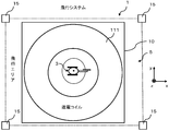
- FIG. 1 is a diagram showing a schematic configuration of a flight system 1.
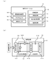
- FIG. It is the figure which looked at the flight system 1 from the upper direction (+ z direction) of FIG. (A) is a figure which shows the hardware constitutions (block diagram) of the flight station 2.
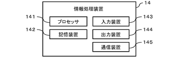
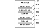
- FIG. 2B is a diagram illustrating a circuit configuration of the power transmission device 10. It is a figure which shows the hardware constitutions (block diagram) of the information processing apparatus 14 (computer) with which the flight station 2 is provided. It is a figure which shows the function (software structure) with which the information processing apparatus 14 is provided.
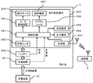
- 2 is a diagram showing a hardware configuration (block diagram) of a flying object 3.
- FIG. 2 is a diagram illustrating a configuration of a power receiving device 20 mounted on a flying object 3.
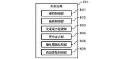
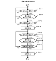
- FIG. It is a figure which shows the function (software structure) with which the control circuit 251 is provided. It is a flowchart explaining power transmission control processing S900. It is a flowchart explaining flight control processing S1000.
- FIG. 1 shows a schematic configuration of a flying system of a flying object (hereinafter referred to as a flying system 1), which is described as an embodiment of the present invention.
- the flight system 1 includes a flight station 2 and a flying body 3.
- the flying station 2 supplies power to the flying object 3 by non-contact power feeding (also referred to as wireless feeding), and the flying object 3 flies by thrust obtained by using this power.
- non-contact power feeding also referred to as wireless feeding
- the flying object 3 flies by thrust obtained by using this power.
- contactless power feeding is performed by a magnetic field resonance method (AC resonance method or DC resonance method) will be described as a preferred embodiment, but the method of contactless power feeding is not necessarily limited to the same method.
- the flight station 2 includes a power transmission device 10 that transmits power to the flying object 3, an information processing device 14, an area sensor 15, and a distance measurement sensor 16.
- the power transmission device 10 transmits power to the flying object 3 by non-contact power feeding of a magnetic field resonance method (AC resonance method or DC resonance method).
- the area sensor 15 and the distance measuring sensor 16 provide information used for determining whether or not the flying object 3 currently exists in the predetermined flight area 5.
- the flight area 5 is described as having a rectangular parallelepiped shape (a space surrounded by a boundary line (boundary surface) indicated by a dotted line in FIG. 1).
- the flying object 3 includes a power receiving device 20 that receives power from the power transmitting device 10 by non-contact power feeding.
- the power receiving device 20 includes a power receiving coil 211 that receives power transmitted from the power transmitting coil 111 of the power transmitting device 10.
- the flying body 3 is, for example, a helicopter, a multicopter, an airplane, an airship, a flying robot, or the like.
- the flying object 3 may be of a type that is remotely controlled by a wireless system (such as a radio control, a radio control, etc.), or of a type that autonomously flies with an autonomous control mechanism. There may be.
- the flying object 3 is operated by a radio signal transmitted from a radio-controlled type (a transmitter operated by a user (for example, a transmitter called a transmitter) (transmitter 6 described later).
- a radio-controlled type a transmitter operated by a user (for example, a transmitter called a transmitter) (transmitter 6 described later).
- transmitter 6 for example, a transmitter called a transmitter
- remote control type A case of remote control type will be described as an example.
- FIG. 2 is a view of the flight system 1 as viewed from above (+ z direction) in FIG.
- the power transmission coil 111 is arranged in such a manner that power can be supplied to the flying body 3 throughout the entire flight area 5.
- the flight area 5 may not necessarily coincide with an area (hereinafter referred to as a power transmission possible area) in which power transmission from the power transmission device 10 to the power reception device 20 can be performed by non-contact power feeding.
- the flight area 5 is set as a region narrower than the power transmittable area in the power transmittable area. For this reason, for example, even when the flying object 3 is slightly out of the flight area 5, the power transmission device 10 supplies the power receiving device 20 with the necessary power without hindering the flight of the flying object 3. Can do.
- the aspect of the power transmission coil 111 and the power reception coil 211 is not necessarily limited.
- a solenoid type or helical type coil may be used as the power transmission coil 111 or the power reception coil 211.
- the power transmission coil 111 and the power reception coil 211 may be in any form that can ensure at least necessary transmission efficiency.
- a highly directional one is selected as the power transmission coil 111 or the power reception coil 211.
- a power transmission coil 111 or a power receiving coil 211 having a broad characteristic with little directivity is selected.
- the power transmission coil 111 is a flat spiral type, and is provided on the bottom surface of the flight area 5 in parallel with the bottom surface (so that the winding axis faces the vertical direction (z-axis direction)). It shall be.
- the power receiving coil 211 is also of a flat spiral type.
- FIG. 3A shows the hardware configuration (block diagram) of the flight station 2.
- the flying station 2 includes an information processing device 14, an area sensor 15, a distance measuring sensor 16, and a power transmission device 10.
- the power transmission device 10 includes a power transmission circuit 11, a power measurement circuit 12 that measures power consumption of the power transmission circuit 11, and a power supply circuit 13.
- FIG. 3B shows a circuit configuration of the power transmission device 10.
- the power transmission circuit 11 includes a power transmission coil 111, a capacitive element 112, and a control circuit 113.
- the power measurement circuit 12 includes a voltmeter 121 and an ammeter 122 that measure the power supplied from the power supply circuit 13 to the power transmission circuit 11.
- the power transmission coil 111 may be capable of adjusting the inductance in order to improve the transmission efficiency of the non-contact power feeding.
- the capacitive element 112 may be capable of adjusting the capacitance so as to improve the transmission efficiency of contactless power feeding.
- the power supply circuit 13 includes, for example, an AC / DC converter and a regulator (a switching system regulator, a linear system regulator, etc.), and supplies power supplied from a commercial power source or the like to the power transmission circuit 11 or the information processing apparatus 14.
- a regulator a switching system regulator, a linear system regulator, etc.
- the control circuit 113 generates a drive current having a predetermined frequency to be supplied to the power transmission circuit 11.
- the control circuit 113 includes, for example, a driver circuit (gate driver, half-bridge driver, etc.), a high frequency amplifier, and a matching circuit (matching circuit).
- FIG. 4 shows a hardware configuration (block diagram) of the information processing apparatus 14 (computer) included in the flying station 2.
- the information processing apparatus 14 includes a processor 141, a storage device 142, an input device 143, and an output device 144. These are connected to be communicable via a communication means such as a bus.
- the processor 141 is configured using, for example, a CPU (Central Processing Unit) or an MPU (Micro Processing Unit).
- the storage device 142 is a device that stores programs and data, and is, for example, a ROM (Read Only Memory), a RAM (Random Access Memory), an NVRAM (Non Volatile RAM), or the like.
- the processor 141 and the storage device 142 may be provided as, for example, a microcomputer (microcomputer) in which these are packaged together.
- the input device 143 is an interface that receives input of information and instructions from the user, and is, for example, a keyboard, a mouse, a touch panel, or the like.
- the output device 144 is an interface that provides information to the user, and is, for example, a liquid crystal panel, an LED (Light Emitting Diode), a speaker, or the like.
- the communication device 145 performs wireless communication with a communication device 259 on the aircraft 3 side described later. This wireless communication is performed using, for example, a radio wave having a frequency of 2.4 GHz band.
- the area sensor 15 detects whether or not the flying object 3 is present at the boundary of the flying area 5 (boundary line, boundary surface, portion indicated by a dotted line in FIG. 1).
- the area sensor 15 includes a plurality of photoelectric sensors including a pair of light emitting units and light receiving units, for example.
- the distance measuring sensor 16 is a sensor that measures the distance between the distance measuring sensor 16 and the flying object 3, and includes, for example, an ultrasonic sensor and a distance image sensor (TOF (Time Of Flight) method, pattern irradiation method, etc.). It is.
- the distance measuring sensor 16 is arranged, for example, so that an area in which the distance can be measured by the distance measuring sensor 16 covers the entire flight area 5. In the present embodiment, the distance measuring sensor 16 is disposed near the center (center) of the power transmission coil 111.
- the flight station 2 may include a plurality of distance measuring sensors 16.
- FIG. 5 shows functions (software configuration) included in the information processing apparatus 14.
- the information processing apparatus 14 includes an operation input receiving unit 501, a flying object position specifying unit 502, a power transmission control unit 503, a power consumption monitoring unit 504, an information output unit 505, and an airframe recognition processing unit 506. It has a function. These functions are realized by, for example, the processor 141 reading and executing a program stored in the storage device 142.
- the operation input receiving unit 501 receives an operation input from the user via the input device 143. For example, the operation input reception unit 501 determines whether or not the user has performed a power transmission start operation (power supply permission operation) or a power transmission stop operation, and notifies the power transmission control unit 503 of the result.
- a power transmission start operation power supply permission operation
- a power transmission stop operation notifies the power transmission control unit 503 of the result.
- the flying object position specifying unit 502 specifies the current position of the flying object 3. For example, the flying object position specifying unit 502 sets the flying object 3 on the boundary of the flying area 5 (each surface (boundary surface, boundary line) except the bottom surface of the rectangular parallelepiped described above) based on the signal input from the area sensor 15. Determine if it exists. Further, the flying object position specifying unit 502 determines the current position of the flying object 3 based on the distance from the ranging sensor 16 to the flying object 3 acquired by the ranging sensor 16. The flying object position specifying unit 502 may comprehensively determine the current position of the flying object 3 based on the measurement values of the one or more area sensors 15 and the measurement values of the one or more ranging sensors 16. .
- the flying object position specifying unit 502 may specify or predict the current position of the flying object 3 based on, for example, the history of measurement values of the area sensor 15 of the flying object 3 or the history of measurement values of the distance measuring sensor 16. Good.
- the flying object position specifying unit 502 may specify the current position of the flying object 3 using a position measuring device other than the area sensor 15 and the distance measuring sensor 16 such as GPS (Global Positioning System).
- the flying object position specifying unit 502 may specify the current position of the flying object 3 based on this change. According to this, a mechanism for determining whether or not the flying object 3 exists in the flying area 5 can be realized with a simple configuration. In the present embodiment, when the flying object 3 exists on the boundary (boundary line, boundary surface) of the flying area 5, the flying object position specifying unit 502 determines that the flying object 3 currently exists outside the flying area 5. It shall be determined.
- the power transmission control unit 503 controls the magnitude (output) of power transmitted from the power transmission coil 111.
- the power transmission control unit 503 controls the magnitude of the power transmitted from the power transmission coil 111 in response to a notification from the operation input reception unit 501 (for example, a notification that the user has performed a power transmission start operation or a power transmission stop operation). To do.
- the power transmission control unit 503 controls the magnitude of the power transmitted from the power transmission coil 111 based on the determination result of the flying object position specifying unit 502, for example.
- the power transmission control unit 503 controls the duty ratio in the PWM control of the driver circuit of the control circuit 113, the coupling coefficient between the power transmission circuit 11 and the power reception circuit 21, the capacitance of the capacitive element 112, and the power supply circuit 13. This is performed by changing one or more of the power supply amount to the circuit 113 and the power supply amount from the control circuit 113 to the power transmission coil 111.
- the power transmission control unit 503 may have a function of adjusting the inductance of the power transmission coil 111 so that the transmission efficiency of contactless power feeding is improved.
- the power transmission control unit 503 may have a function of adjusting the capacitance of the capacitive element 112 so that the transmission efficiency of contactless power feeding is improved (see, for example, Patent Documents 3 to 5).
- the power transmission control unit 503 grasps the transmission efficiency based on the ratio between the power transmission amount from the power transmission circuit 11 and the power reception amount of the power receiving device 20 acquired from the flying vehicle 3 via the communication device 145.
- the power transmission control unit 503 grasps the transmission efficiency based on the measurement value of the power measurement circuit 12, for example.
- the power consumption monitoring unit 504 monitors the power consumption of the power transmission circuit 11 as needed based on information (voltage value, current value) obtained from the power measurement circuit 12.
- the information output unit 505 outputs various information to be described later to the output device 144.
- the aircraft recognition processing unit 506 performs authentication based on the authentication information acquired from the flying object 3 (confirmation of whether or not the flying object 3 can be a power supply target).
- the authentication information is acquired, for example, when the communication device 145 wirelessly communicates with the communication device 259 of the flying object 3.
- the aircraft recognition processing unit 506 authenticates the flying object 3, for example, it is possible to prevent malfunction or theft prevention of other company's products or similar products existing nearby.
- FIG. 6 shows a hardware configuration (block diagram) of the flying object 3.
- the flying object 3 includes a power receiving device 20 and a flight control device 250 that receives power supply from the power receiving device 20.
- the flight control device 250 includes a control circuit 251, a receiver 252, various sensors 253, a motor control device 254, a power motor 255, an actuator 256, a steering mechanism 257, an output device 258, a communication device 259, and a battery 260.
- the control circuit 251 includes a processor and a storage element and functions as an information processing apparatus.
- the control circuit 251 may be realized by, for example, a microcomputer (microcomputer) in which a processor and a storage element are packaged as an integral unit.
- the various sensors 253 are, for example, a 3-axis gyro sensor (angular velocity sensor), a 3-axis acceleration sensor, an atmospheric pressure sensor, a magnetic sensor, an ultrasonic sensor, a GPS (Global Positioning System), and the like.
- the three-axis gyro sensor detects, for example, the front / rear / left / right inclination and the angular velocity of rotation of the flying object 3.
- the triaxial acceleration sensor detects, for example, the acceleration of the flying object 3 (acceleration in the front, rear, left, right, up and down directions).
- the atmospheric pressure sensor measures the atmospheric pressure for obtaining the altitude and the ascending / descending speed of the flying object 3.
- the magnetic sensor detects, for example, the direction in which the aircraft's axis is currently facing.
- An ultrasonic sensor detects the distance between the flying body 3, and the ground, a wall, an obstacle, etc., for example. Note that the flying object 3 does not necessarily have to include all the sensors exemplified above.
- the receiver 252 receives the radio signal transmitted from the remote control transmitter 6 and inputs the content of the received radio signal to the control circuit 251.
- the motor control device 254 (also referred to as ESC (Electronic Speed Controller), amplifier, etc.) controls the rotation of the power motor 255 by, for example, electrical resistance value control or PWM (Pulse Width Modulation) control.
- the motor control device 254 constitutes a thrust generation mechanism that generates thrust for flight.
- the power motor 255 constitutes a thrust generation mechanism together with the motor control device 254.
- the power motor 255 is an electric motor, for example, a brushless motor.
- the power motor 255 When the flying object 3 is a helicopter, for example, the power motor 255 generates the rotational force of the main rotor and the tail rotor. Further, when the flying object 3 is an airplane, for example, the power motor 255 generates a rotational force of a propeller for obtaining a thrust. Further, when the flying object 3 is, for example, a multicopter, the power motor 255 generates the rotational force of the propeller that generates thrust.
- the actuator 256 is configured using, for example, a servo motor or an electromagnet, and controls the steering mechanism 257 according to a signal (for example, a PWM signal) sent from the control circuit 251.
- a signal for example, a PWM signal
- the steering mechanism 257 includes, for example, a mechanical mechanism controlled by an actuator 256.
- the mechanical mechanism converts the force generated by the actuator 256 into a control force such as pitch, aileron, elevator, ladder (tail rotor pitch), etc. Convert.
- the mechanical mechanism converts the force generated by the actuator 256 into a force for controlling an aileron, an elevator, a ladder, or the like.
- the steering mechanism 257 is not an essential component of the flying object 3 (for example, the multicopter performs steering by controlling the rotational speeds of the plurality of power motors 255).
- the output device 258 is an interface that provides information to the user, such as an LED or a speaker.
- the output device 258 outputs information indicating that, for example, when the flying object 3 is out of the flight area 5 (LED blinking, warning sound output, etc.).
- the communication device 259 performs wireless communication with the communication device 145 on the flight station 2 side.
- the control circuit 251 stores authentication information and transmits the authentication information to the flying station 2 via the communication device 259.
- the battery 260 is, for example, a lithium ion secondary battery, a lithium polymer secondary battery, or an electric double layer capacitor (electric double layer capacitor).
- the battery 260 has a capacity necessary for safely landing the flying object 3 when power transmission from the power transmission device 10 is interrupted for some reason, and is lightweight.
- the battery 260 is charged by the power received by the power receiving device 20 during the flight or landing of the flying object 3.
- the voltage between the terminals of the battery 260 is input to the control circuit 251.
- the control circuit 251 grasps the remaining amount of the battery 260 based on the inter-terminal voltage. For example, the control circuit 251 outputs information indicating the current remaining amount of the battery 260 from the output device 258.
- the battery 260 is not an essential configuration, and the flying object 3 may not include the battery 260.
- the flying body 3 does not include the battery 260, for example, power for driving the power motor 255 is directly supplied from the power receiving device 20 to the flight control device 250.
- the flight system 1 is provided as, for example, a toy, the weight can be easily reduced by not mounting the battery 260, and the mobility and safety of the flying object 3 can be easily improved. .
- FIG. 7 shows a configuration of the power receiving device 20 mounted on the flying object 3.
- the power receiving device 20 rectifies the power received by the power receiving circuit 21 (including the power receiving coil 211 and the capacitor 212) that performs magnetic resonance type non-contact power feeding, and loads ( The rectifier circuit 22 supplied to the flight control device 250, the battery 260, etc.) and the received power supplied to the load are measured, and the measured value is input to the control circuit 251 described later (voltmeter 241 and current). A total of 242).
- the power receiving coil 211 may be capable of adjusting the inductance.
- the capacitor 212 may be one that can adjust the capacitance.
- FIG. 8 shows functions (software configuration) included in the control circuit 251.
- the control circuit 251 includes an attitude control unit 801, a steering control unit 802, a received power monitoring unit 803, a warning output unit 804, a body recognition processing unit 805, and an automatic landing control unit 806. These functions are realized, for example, when the processor of the control circuit 251 reads and executes a program stored in the storage device of the control circuit 251.
- the attitude control unit 801 controls the flight attitude of the flying object 3 by controlling the motor control device 254 and the actuator 256 (the power motor 255 and the steering mechanism 257) according to signals input from the various sensors 253.
- the steering control unit 802 controls the motor control device 254 and the actuator 256 (the power motor 255 and the steering mechanism 257) according to the signal input from the receiver 252, and the operation of the flying object 3 (three axes (yaw angle, Roll angle, pitch angle) direction change, ascending, descending, turning, etc.).
- the received power monitoring unit 803 monitors the received power of the power receiving device 20 based on the measured values of voltage and current input from the power measuring circuit 24 of the power receiving device 20.
- the received power monitoring unit 803 notifies the power transmission device 10 of the measurement value via the communication device 259.
- the warning output unit 804 When the received power monitoring unit 803 detects that the amount of received power is equal to or less than the threshold, the warning output unit 804 outputs information indicating that power reception is not sufficiently performed to the output device 258.
- the aircraft recognition processing unit 805 stores the authentication information and transmits the authentication information to the communication device 145 of the flight station 2 via the communication device 259.
- the automatic landing control unit 806 makes the motor control device 254 or the like so as to safely land (soft landing) the flying object 3 when detecting that the amount of received power is less than or equal to the threshold (for example, gradually lowering the buoyancy).
- the actuator 256 (power motor 255 and steering mechanism 257) is controlled.
- FIG. 9 is a flowchart illustrating a process (hereinafter referred to as a power transmission control process S900) performed on the flight station 2 side.
- a power transmission control process S900 a process performed on the flight station 2 side.
- the power transmission control process S900 will be described with reference to FIG.
- the aircraft recognition processing unit 506 of the flying station 2 first determines whether or not the flying object 3 can be recognized. Specifically, the aircraft recognition processing unit 506 receives the authentication information from the flying object 3 and performs the above determination by performing authentication based on the received authentication information (S911: NO).
- the flying object position specifying unit 502 of the flying station 2 uses the method described above, and the flying object 3 is currently flying. It is determined whether or not the area 5 exists (S912).
- the flying object position specifying unit 502 determines that the flying object 3 currently exists in the flying area 5 (S912: YES)
- the process proceeds to S913.
- the flying object position specifying unit 502 determines that the flying object 3 currently exists outside the flying area 5 (S912: NO)
- the process returns to S911.
- the operation input reception unit 501 of the flight station 2 determines whether or not the user has performed a power transmission start operation (power supply permission operation) (S913: NO). If it is determined that the user has performed a power transmission start operation (S913: YES), this is notified to the power transmission control unit 503, and the power transmission control unit 503 starts power transmission (the power transmission coil 111 is energized) (S914). In addition, without waiting for the user's power transmission start operation, the flying object position specifying unit 502 automatically determines that the flying object 3 currently exists in the flying area 5 (S912: YES), and the power transmission control unit 503 automatically Power transmission may be started.
- a power transmission start operation power supply permission operation
- the aircraft recognition processing unit 506 of the flying station 2 monitors in real time whether or not the flying vehicle 3 can be recognized (S915). When the aircraft recognition processing unit 506 cannot recognize the flying object 3 (S915: NO), the aircraft transmission processing unit 503 notifies the power transmission control unit 503 to that effect, and the power transmission control unit 503 stops the power transmission (S918). Thereafter, the process returns to S911.
- the flying object position specifying unit 502 of the flying station 2 monitors in real time whether or not the flying object 3 exists in the flying area 5 (S916). When the flying object 3 does not exist in the flying area 5 (S916: NO), the flying object position specifying unit 502 notifies the power transmission control unit 503 to that effect, and the power transmission control unit 503 stops the power transmission in response to the notification. (S918). Thereafter, the process returns to S911.
- the operation input reception unit 501 of the flight station 2 monitors in real time whether or not the user has performed a power transmission stop operation (S917). If the operation input reception unit 501 determines that the user has performed a power transmission stop operation (S917: YES), the operation input reception unit 501 notifies the power transmission control unit 503 to that effect, and the power transmission control unit 503 receives this and stops power transmission (S918). . Thereafter, the process returns to S911.
- FIG. 10 is a flowchart illustrating a process performed in the flying object 3 (hereinafter referred to as a flight control process S1000).
- a flight control process S1000 a process performed in the flying object 3
- the flight control process S1000 will be described with reference to FIG.
- the control circuit 251 of the flying object 3 measures the voltage value (or current value) measured by the voltmeter 241 (or ammeter 242) of the power measurement circuit 24 of the power receiving device 20. Is determined to exceed a preset voltage threshold (or current threshold) (whether or not power necessary for flight can be received) (S1011). When it is determined that the voltage value (or current value) exceeds the voltage threshold value (or current threshold value) (S1011: YES), the control circuit 251 subsequently determines whether or not a control instruction is input from the receiver 252. Determination is made (S1012). If a control instruction is input from the receiver 252 (S1012: YES), the process proceeds to S1013. On the other hand, when a control instruction is not input from the receiver 252 (S1012: NO), the process proceeds to S1014.
- control circuit 251 controls the power motor 255 and the steering mechanism 257 according to the control instruction.
- control circuit 251 performs feedback control of the power motor 255 and the steering mechanism 257 according to values input from the various sensors 253, and autonomously controls the attitude of the flying object 3.
- the control circuit 251 sets the voltage value (or current value) measured by the voltmeter 241 (or ammeter 242) of the power measurement circuit 24 of the power receiving device 20 for each of the voltage threshold values (or current threshold values) set in advance. It is determined in real time whether or not the power required for the flight is received (S1015). When the voltage value (or current value) exceeds the voltage threshold value (or current threshold value) (S1015: YES), the process returns to S1012. On the other hand, when the voltage value (or current value) does not exceed the voltage threshold value (or current threshold value) (S1015: NO), the control circuit 251 outputs a warning that the power reception is insufficient (LED blinking or warning). Audio output, etc.) is started (S1016), and an operation for landing (soft landing) is started (S1017).
- the control circuit 251 determines whether or not the flying object 3 has landed. For example, the control circuit 251 determines that the flying object 3 has landed when the rotation of the power motor 255 has stopped for a predetermined time or longer (or is equal to or lower than a preset threshold rotation speed). For example, the control circuit 251 determines that the flying object 3 has landed when the actuator 256 has not been controlled for a predetermined time or longer.
- the flying object 3 when the flying object 3 does not exist in the flying area 5, the power transmitted from the power transmission device 10 is reduced (in the above example, power transmission is stopped), so the flying object 3 moves to a place away from the flying area 5. Can be prevented.
- the control circuit 25 forces the landing of the flying object 3. Etc. may not be performed (it is left to the user's control). Further, for example, when the remaining amount of the battery 260 is sufficient, the control circuit 251 may only output a warning.
- the flying object 3 knows its current position and does not depart from the flying area 5 (so that the flying object 3 is located in the flying area 5 (except on the boundary of the flying area 5). )
- the flying station 2 grasps the current position of the flying object 3 in real time by wireless communication, and the flying of the flying object 3 is automatically performed so that the flying object 3 does not deviate from the flying area 5)
- the flying object 3 can automatically fly in the flight area 5 semipermanently. Even in that case, power transmission stops if the flying object 3 departs from the flying area 5 for some reason (such as equipment failure or wind) (S916 to S918 in FIG. 9). It can prevent moving to a remote place.
- a toy, a display product (exhibit), or the like in which the flying object 3 automatically and semipermanently flies in the flight area 5 can be realized.
- the flying vehicle 3 obtains thrust using the received power. Therefore, the battery may not be mounted on the flying body 3 or may have a small capacity (light weight) (battery 260), and the flying body 3 can be reduced in weight. Therefore, the flight performance of the flying object 3 can be improved, the impact at the time of a crash or collision can be reduced, and the durability and safety of the flying object 3 can be improved.
- the battery may not be mounted on the flying body 3 or may have a small capacity (light weight) (battery 260), and the flying body 3 can be reduced in weight. Therefore, the flight performance of the flying object 3 can be improved, the impact at the time of a crash or collision can be reduced, and the durability and safety of the flying object 3 can be improved.
- the flying object 3 can fly for a long time. For example, it is possible to practice for a long time. Moreover, since it is not necessary to charge before flight, it is also released from the troublesomeness of charging.
- the battery may not be mounted on the flying object 3 or may be a small capacity (light weight) / low price (battery 260), the running cost can be suppressed.
- the flight system 1 described above may be provided as a toy or an educational toy. Further, the flight system 1 can be used for, for example, practice of operating a flying object 3 (helicopter, multicopter, airplane, airship, flying robot, etc.) of a type that is remotely controlled by a wireless method.
- a flying object 3 helicopter, multicopter, airplane, airship, flying robot, etc.
- the present invention made by the present inventor has been specifically described based on the embodiments.
- the present invention is not limited to the above-described embodiments, and various modifications can be made without departing from the scope of the invention. Needless to say.
- the above-described embodiment has been described in detail for easy understanding of the present invention, and is not necessarily limited to the one having all the configurations described. Further, it is possible to add, delete, and replace other configurations for a part of the configuration of the above embodiment.
- the above-described configurations, functional units, processing units, processing means, etc. may be realized in hardware by designing a part or all of them, for example, with an integrated circuit.
- Each of the above-described configurations, functions, and the like may be realized by software by the processor interpreting and executing a program that realizes each function.
- Information such as programs, tables, and files for realizing each function can be stored in a recording device such as a memory, a hard disk, or an SSD (Solid State Drive), or a recording medium such as an IC card, an SD card, or a DVD.
- control lines and information lines indicate what is considered necessary for explanation, and not all control lines and information lines on the mounting are necessarily shown. For example, it may be considered that almost all configurations are actually connected to each other.
- the arrangement form of various functional units in the flight system 1 described above is merely an example.
- the arrangement form of the various functional units can be changed to an optimum arrangement form from the viewpoints of hardware and software performance, processing efficiency, communication efficiency, and the like included in the flight system 1.
- a part of the functions provided on the flying station 2 side may be provided in the flying object 3.
- the flying object 3 when the flying object 3 is out of the flight area 5, the power transmission from the power transmission device 10 is stopped and the flying object 3 immediately starts the landing operation.
- the predetermined amount of condition for example, the amount of charge of the battery 260 when the power transmission from the power transmission device 10 is stopped exceeds the predetermined value, the landing operation may not be automatically performed. Further, when the flying object 3 enters the flight area 5 again after that, the power supply from the power transmission device 10 to the power reception device 20 may be resumed.
Landscapes
- Engineering & Computer Science (AREA)
- Computer Networks & Wireless Communication (AREA)
- Chemical & Material Sciences (AREA)
- Combustion & Propulsion (AREA)
- Aviation & Aerospace Engineering (AREA)
- Power Engineering (AREA)
- Charge And Discharge Circuits For Batteries Or The Like (AREA)
Abstract
Dans la présente invention, un véhicule volant 3 est pourvu d'un dispositif de réception d'énergie 20 qui reçoit de l'énergie par charge sans contact par résonance magnétique, et d'un mécanisme de génération de propulsion (moteur de puissance motrice 255, dispositif de commande de moteur 254) afin d'assurer la propulsion pour le vol à l'aide de l'énergie reçue par le dispositif de réception d'énergie 20. Lorsque le véhicule volant 3 est en vol, de l'énergie est transmise au dispositif de réception d'énergie 20 par charge sans contact à partir d'un dispositif d'émission d'énergie 10 qui est situé à un emplacement éloigné du véhicule volant 3. La présente invention est pourvue de capteurs (capteurs de zone 15, capteur de mesure de distance 16) qui fournissent des informations utilisées pour déterminer si le véhicule volant 3 se trouve ou non à l'intérieur d'une zone de vol 5 définie à l'avance, et d'un dispositif de traitement d'informations 14. Le dispositif de traitement d'informations 14 détermine si le véhicule volant 3 se trouve actuellement à l'intérieur de la zone de vol 5 sur la base des informations, et réduit la puissance émise par le dispositif d'émission d'énergie 10 s'il est déterminé que le véhicule volant 3 ne se trouve pas dans la zone de vol 5.
Priority Applications (2)
| Application Number | Priority Date | Filing Date | Title |
|---|---|---|---|
| PCT/JP2016/065271 WO2017203590A1 (fr) | 2016-05-24 | 2016-05-24 | Système de vol pour véhicule volant, et procédé de vol pour véhicule volant |
| JP2017503182A JP6179688B1 (ja) | 2016-05-24 | 2016-05-24 | 飛行体の飛行システム、及び飛行体の飛行方法 |
Applications Claiming Priority (1)
| Application Number | Priority Date | Filing Date | Title |
|---|---|---|---|
| PCT/JP2016/065271 WO2017203590A1 (fr) | 2016-05-24 | 2016-05-24 | Système de vol pour véhicule volant, et procédé de vol pour véhicule volant |
Publications (1)
| Publication Number | Publication Date |
|---|---|
| WO2017203590A1 true WO2017203590A1 (fr) | 2017-11-30 |
Family
ID=59604877
Family Applications (1)
| Application Number | Title | Priority Date | Filing Date |
|---|---|---|---|
| PCT/JP2016/065271 Ceased WO2017203590A1 (fr) | 2016-05-24 | 2016-05-24 | Système de vol pour véhicule volant, et procédé de vol pour véhicule volant |
Country Status (2)
| Country | Link |
|---|---|
| JP (1) | JP6179688B1 (fr) |
| WO (1) | WO2017203590A1 (fr) |
Cited By (7)
| Publication number | Priority date | Publication date | Assignee | Title |
|---|---|---|---|---|
| JP2019170014A (ja) * | 2018-03-22 | 2019-10-03 | 株式会社Soken | 電源装置およびこれを用いた飛行装置 |
| JP2020117168A (ja) * | 2019-01-28 | 2020-08-06 | 三菱ロジスネクスト株式会社 | 無人飛行体用給電システム |
| JP2020121630A (ja) * | 2019-01-30 | 2020-08-13 | 三菱ロジスネクスト株式会社 | 無人飛行体用給電システム |
| JP2021059293A (ja) * | 2019-10-09 | 2021-04-15 | 三菱電機株式会社 | 無線電力伝送システム及び無線電力伝送方法 |
| WO2021087780A1 (fr) * | 2019-11-05 | 2021-05-14 | 深圳市大疆创新科技有限公司 | Procédé de commande de vol, procédé d'alimentation électrique, système et engin volant sans pilote |
| JP2021123199A (ja) * | 2020-02-04 | 2021-08-30 | 株式会社デンソー | 無線給電システム |
| KR20220148357A (ko) * | 2021-04-28 | 2022-11-07 | 주식회사 웨이브쓰리디 | 드론의 무선 충전 시스템 |
Families Citing this family (3)
| Publication number | Priority date | Publication date | Assignee | Title |
|---|---|---|---|---|
| ES2938195T3 (es) * | 2017-08-17 | 2023-04-05 | Columbiad Launch Services Inc | Sistema y método para distribuir energía a sistemas de aeronaves |
| KR102299718B1 (ko) * | 2019-10-15 | 2021-09-08 | 경희대학교 산학협력단 | 카메라 영상을 이용한 무선전력 전송 가능한 드론 경기장 시스템 |
| KR102299719B1 (ko) * | 2019-10-15 | 2021-09-08 | 경희대학교 산학협력단 | 전력검출센서를 이용한 무선전력 전송 가능한 드론 경기장 시스템 |
Citations (2)
| Publication number | Priority date | Publication date | Assignee | Title |
|---|---|---|---|---|
| JP2012504387A (ja) * | 2008-09-27 | 2012-02-16 | ウィトリシティ コーポレーション | 無線エネルギー伝達システム |
| JP2014500827A (ja) * | 2010-12-09 | 2014-01-16 | ザ・ボーイング・カンパニー | 無人ビークル及びシステム |
Family Cites Families (1)
| Publication number | Priority date | Publication date | Assignee | Title |
|---|---|---|---|---|
| JP2012500619A (ja) * | 2008-08-19 | 2012-01-05 | クゥアルコム・インコーポレイテッド | ポータブルワイヤレス電力充電のためのワイヤレス電力送信 |
-
2016
- 2016-05-24 WO PCT/JP2016/065271 patent/WO2017203590A1/fr not_active Ceased
- 2016-05-24 JP JP2017503182A patent/JP6179688B1/ja active Active
Patent Citations (2)
| Publication number | Priority date | Publication date | Assignee | Title |
|---|---|---|---|---|
| JP2012504387A (ja) * | 2008-09-27 | 2012-02-16 | ウィトリシティ コーポレーション | 無線エネルギー伝達システム |
| JP2014500827A (ja) * | 2010-12-09 | 2014-01-16 | ザ・ボーイング・カンパニー | 無人ビークル及びシステム |
Cited By (9)
| Publication number | Priority date | Publication date | Assignee | Title |
|---|---|---|---|---|
| JP2019170014A (ja) * | 2018-03-22 | 2019-10-03 | 株式会社Soken | 電源装置およびこれを用いた飛行装置 |
| JP2020117168A (ja) * | 2019-01-28 | 2020-08-06 | 三菱ロジスネクスト株式会社 | 無人飛行体用給電システム |
| JP2020121630A (ja) * | 2019-01-30 | 2020-08-13 | 三菱ロジスネクスト株式会社 | 無人飛行体用給電システム |
| JP2021059293A (ja) * | 2019-10-09 | 2021-04-15 | 三菱電機株式会社 | 無線電力伝送システム及び無線電力伝送方法 |
| WO2021087780A1 (fr) * | 2019-11-05 | 2021-05-14 | 深圳市大疆创新科技有限公司 | Procédé de commande de vol, procédé d'alimentation électrique, système et engin volant sans pilote |
| JP2021123199A (ja) * | 2020-02-04 | 2021-08-30 | 株式会社デンソー | 無線給電システム |
| JP7318549B2 (ja) | 2020-02-04 | 2023-08-01 | 株式会社デンソー | 無線給電システム |
| KR20220148357A (ko) * | 2021-04-28 | 2022-11-07 | 주식회사 웨이브쓰리디 | 드론의 무선 충전 시스템 |
| KR102578231B1 (ko) * | 2021-04-28 | 2023-09-15 | 주식회사 웨이브쓰리디 | 드론의 무선 충전 시스템 |
Also Published As
| Publication number | Publication date |
|---|---|
| JPWO2017203590A1 (ja) | 2018-06-07 |
| JP6179688B1 (ja) | 2017-08-16 |
Similar Documents
| Publication | Publication Date | Title |
|---|---|---|
| JP6179688B1 (ja) | 飛行体の飛行システム、及び飛行体の飛行方法 | |
| EP3372492B1 (fr) | Système et procédé de commande de décollage et d'atterrissage d'aéronef sans pilote | |
| CN115379987B (zh) | 一种适用于包裹递送的模块化无人机系统 | |
| US10870479B2 (en) | Multi-architecture modular unmanned aerial system | |
| CN113165551B (zh) | 调节无人机的充电的电力通信 | |
| JP6179687B1 (ja) | 無人飛行体、受電コイルユニット、及び充電システム | |
| US20190126769A1 (en) | UAV Group Charging Based on Demand for UAV Service | |
| CN106655322B (zh) | 服务型无人机、无人机充电系统及充电方法 | |
| JP6156605B1 (ja) | 無人飛行体、充電システム、及び充電システムの制御方法 | |
| CN110621250A (zh) | 用于无人驾驶飞行器的电气系统 | |
| JP7275612B2 (ja) | 飛行体の着陸ポート、及び飛行体の着陸方法 | |
| JP6480088B1 (ja) | 飛行制御システム及び飛行計画作成方法 | |
| AU2021369576A1 (en) | Systems and methods for battery capacity management in a fleet of UAVs | |
| EP3728031A1 (fr) | Appareil de couplage de charge utile pour un uav et procédé de livraison d'une charge utile | |
| EP4598809A1 (fr) | Uav comprenant une ou plusieurs portes de soute de chargement inférieures | |
| WO2019113573A1 (fr) | Structure d'aile moulée par injection pour véhicules aériens | |
| CN114845934B (zh) | 用于停止操作构件移动的系统和方法 | |
| CN106672230A (zh) | 涵道式无人机 | |
| JP2016210403A (ja) | 無人飛行体 | |
| JP2016210404A (ja) | 無人飛行体 | |
| WO2023047177A1 (fr) | Système de charge de véhicule aérien sans pilote | |
| JP2021062772A (ja) | 給電システム |
Legal Events
| Date | Code | Title | Description |
|---|---|---|---|
| ENP | Entry into the national phase |
Ref document number: 2017503182 Country of ref document: JP Kind code of ref document: A |
|
| NENP | Non-entry into the national phase |
Ref country code: DE |
|
| 121 | Ep: the epo has been informed by wipo that ep was designated in this application |
Ref document number: 16903072 Country of ref document: EP Kind code of ref document: A1 |
|
| 122 | Ep: pct application non-entry in european phase |
Ref document number: 16903072 Country of ref document: EP Kind code of ref document: A1 |